

Page 1
PIONEER CORPORATION 4-1, Meguro 1-chome, Meguro-ku, Tokyo 153-8654, Japan
PIONEER ELECTRONICS (USA) INC. P.O. Box 1760, Long Beach, CA 90801-1760, U.S.A.
PIONEER EUROPE NV Haven 1087, Keetberglaan 1, 9120 Melsele, Belgium
PIONEER ELECTRONICS ASIACENTRE PTE. LTD. 253 Alexandra Road, #04-01, Singapore 159936
PIONEER CORPORATION 2006
÷ When servicing this model, some service procedures may reset the customer settings
to the factory default settings. Make sure to explain this to the customer.
An HDD (Hard Disc Drive) is mounted in this product.
The HDD is a precision instrument very vulnerable to shock and electrostatic charges. Please read
"7.3 Cautions on Handling the HDD" in this manual and exercise sufficient caution when handling the
HDD itself, as well as the product with the HDD built in.
When an HDD becomes defective and inoperable, restoration of the user's data recorded on the HDD,
or copying of the user's recorded data to other media (such as a new HDD) is totally impossible.
Before servicing, OBTAIN THE USER'S PRIOR CONSENT to that effect.
The user must be made aware that all recorded data are deleted if the HDD is intialized.
HDD/DVD
HDD HDD DVD
DVR-640H-AV
ORDER NO.
RRV3368
DVD RECORDER
DVR-640H-AV
DVR-540H-S
THIS MANUAL IS APPLICABLE TO THE FOLLOWING MODEL(S) AND TYPE(S).
Serial No.
Model Type Power Requirement Region No.
DVR-640H-AV WYXK5 AC220-240V 2 &&UK######$$
DVR-640H-AV WYXV5 AC220-240V 2 &&DL######$$
DVR-540H-S WYXK5 AC220-240V 2 &&UK######$$
DVR-540H-S WYXV5 AC220-240V 2 &&DL######$$
DVR-540H-S WYXVRE5 AC220-240V 5 &&DL######$$
Please confirm 3rd & 4th
alphabetical letters.
For details, refer to "Important Check Points for Good Servicing" .
T-ZZV APR. 2006 printed in Japan
Page 2
1234
SAFETY INFORMATION
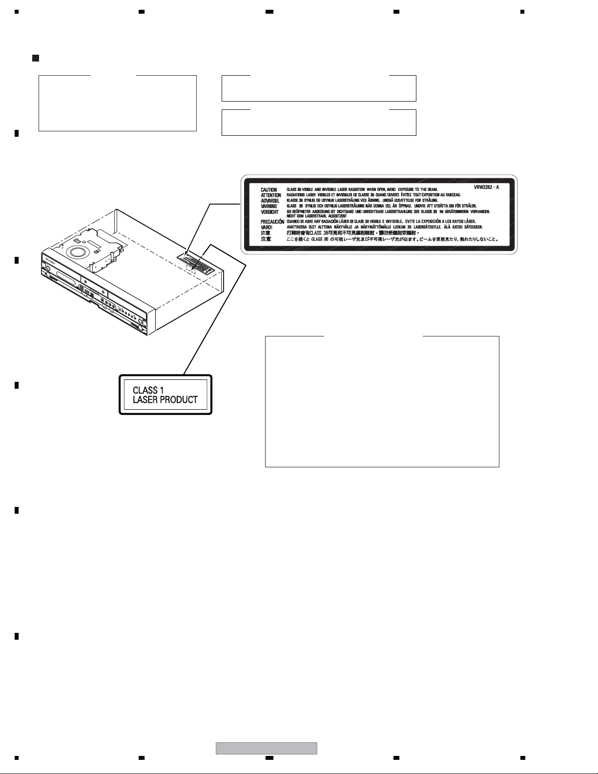
LABEL CHECK
A
IMPORTANT
THIS PIONEER APPARATUS CONTAINS
LASER OF CLASS 1.
SERVICING OPERATION OF THE APPARATUS
SHOULD BE DONE BY A SPECIALLY
INSTRUCTED PERSON.
B
MAXIMUM OUTPUT POWER: 100 mW
LASER DIODE CHARACTERISTICS
WAVELENGTH: 654 - 662 nm
LASER DIODE CHARACTERISTICS
MAXIMUM OUTPUT POWER: 5 mW
WAVELENGTH: 770 - 810 nm
VRW2262
H
D
D
H
H
D
D
D
D
/
D
D
V
V
D
D
C
Additional Laser Caution
1. The ON/OFF(ON:low level,OFF:high level) status of the
CLAMP signals for detecting the loading state are detected
by the drive CPUs, and the design prevents laser diode
oscillation when the CLAMP signal turns OFF.
In normal operation, if no disc is clamped, the laser diode
oscillation is disabled.
However, the interlock does not always operate in the test
mode.
2. When the cover is opened, close viewing of the objective
D
lens with the naked eye will cause exposure to a Class 3A
laser beam.
E
F
2
DVR-640H-AV
1234
Page 3
5678
[Important Check Points for Good Servicing]
In this manual, procedures that must be performed during repairs are marked with the below symbol.
Please be sure to confirm and follow these procedures.
1. Product safety
Please conform to product regulations (such as safety and radiation regulations), and maintain a safe servicing environment by
following the safety instructions described in this manual.
1 Use specified parts for repair.
Use genuine parts. Be sure to use important parts for safety.
2 Do not perform modifications without proper instructions.
Please follow the specified safety methods when modification(addition/change of parts) is required due to interferences such as
radio/TV interference and foreign noise.
3 Make sure the soldering of repaired locations is properly performed.
When you solder while repairing, please be sure that there are no cold solder and other debris.
Soldering should be finished with the proper quantity. (Refer to the example)
4 Make sure the screws are tightly fastened.
Please be sure that all screws are fastened, and that there are no loose screws.
5 Make sure each connectors are correctly inserted.
Please be sure that all connectors are inserted, and that there are no imperfect insertion.
6 Make sure the wiring cables are set to their original state.
Please replace the wiring and cables to the original state after repairs.
In addition, be sure that there are no pinched wires, etc.
7 Make sure screws and soldering scraps do not remain inside the product.
Please check that neither solder debris nor screws remain inside the product.
8 There should be no semi-broken wires, scratches, melting, etc. on the coating of the power cord.
Damaged power cords may lead to fire accidents, so please be sure that there are no damages.
If you find a damaged power cord, please exchange it with a suitable one.
9 There should be no spark traces or similar marks on the power plug.
When spark traces or similar marks are found on the power supply plug, please check the connection and advise on secure
connections and suitable usage. Please exchange the power cord if necessary.
0 Safe environment should be secured during servicing.
When you perform repairs, please pay attention to static electricity, furniture, household articles, etc. in order to prevent injuries.
Please pay attention to your surroundings and repair safely.
A
B
C
D
2. Adjustments
To keep the original performance of the products, optimum adjustments and confirmation of characteristics within specification.
Adjustments should be performed in accordance with the procedures/instructions described in this manual.
3. Lubricants, Glues, and Replacement parts
Use grease and adhesives that are equal to the specified substance.
Make sure the proper amount is applied.
4. Cleaning
For parts that require cleaning, such as optical pickups, tape deck heads, lenses and mirrors used in projection monitors, proper
cleaning should be performed to restore their performances.
5. Shipping mode and Shipping screws
To protect products from damages or failures during transit, the shipping mode should be set or the shipping screws should be
installed before shipment. Please be sure to follow this method especially if it is specified in this manual.
56
DVR-640H-AV
E
F
3
7
8
Page 4

1234
CONTENTS
SAFETY INFORMATION..................................................................................................................................... 2
1. SPECIFICATIONS ............................................................................................................................................ 5
2. EXPLODED VIEWS AND PARTS LIST............................................................................................................ 8
A
B
C
D
E
2.1 PACKING ...................................................................................................................................................8
2.2 EXTERIOR SECTION.............................................................................................................................. 10
2.3 FRONT PANEL SECTION ....................................................................................................................... 12
3. BLOCK DIAGRAM AND SCHEMATIC DIAGRAM..........................................................................................14
3.1 BLOCK DIAGRAM ................................................................................................................................... 14
3.1.1 OVERALL BLOCK DIAGRAM............................................................................................................ 14
3.1.2 DETECTION AND ENCODE SYSTEM BLOCK DIAGRAM............................................................... 16
3.1.3 POWER BLOCK ................................................................................................................................17
3.2 OVERALL WIRING DIAGRAM................................................................................................................. 18
3.3 TUJB ASSY (1/4) ..................................................................................................................................... 20
3.4 TUJB ASSY (2/4) ..................................................................................................................................... 22
3.5 TUJB ASSY(3/4) ...................................................................................................................................... 24
3.6 TUJB ASSY(4/4) ...................................................................................................................................... 26
3.7 SCRB ASSY ............................................................................................................................................ 28
3.8 FJKB, FLKY and KEYB ASSYS............................................................................................................... 30
3.9 MAIN ASSY(1/4) ...................................................................................................................................... 32
3.10 MAIN ASSY(2/4) .................................................................................................................................... 34
3.11 MAIN ASSY(3/4) .................................................................................................................................... 36
3.12 MAIN ASSY(4/4) .................................................................................................................................... 38
3.13 DVJB ASSY (DVR-640H-AV Only)......................................................................................................... 40
3.14 USBB ASSY (DVR-640H-AV Only) ........................................................................................................ 42
3.15 ATAB ASSY ............................................................................................................................................ 43
3.16 POWER SUPPLY UNIT.......................................................................................................................... 44
3.17 WAVE FORMS ....................................................................................................................................... 48
4. PCB CONNECTION DIAGRAM ..................................................................................................................... 53
4.1 TUJB ASSY.............................................................................................................................................. 54
4.2 SCRB ASSY ............................................................................................................................................ 58
4.3 FJKB, FLKY and KEYB ASSYS............................................................................................................... 60
4.4 MAIN ASSY ............................................................................................................................................. 62
4.5 DVJB ASSY (DVR-640H-AV Only)........................................................................................................... 66
4.6 USBB ASSY (DVR-640H-AV Only) .......................................................................................................... 68
4.7 ATAB ASSY .............................................................................................................................................. 70
4.8 POWER SUPPLY UNIT............................................................................................................................ 72
5. PCB PARTS LIST ........................................................................................................................................... 76
6. ADJUSTMENT ............................................................................................................................................... 83
7. GENERAL INFORMATION............................................................................................................................. 85
7.1 DIAGNOSIS ............................................................................................................................................. 85
7.1.1 MODEL SETTING.............................................................................................................................. 87
7.1.2 CPRM ID NUMBER AND DATA SETTING......................................................................................... 88
7.1.3 FIRMWARE DOWNLOADING METHOD........................................................................................... 92
7.1.4 VIDEO ADJUSTMENT FOR SPECIFIC AREA.................................................................................. 95
7.1.5 SERVICE MODE................................................................................................................................ 99
7.1.6 DV SERVICE MODE........................................................................................................................ 111
7.1.7 EPG SERVICE MODE..................................................................................................................... 114
7.1.8 AGING MODE.................................................................................................................................. 116
7.1.9 HDD CHECK MODE........................................................................................................................ 118
7.1.10 DIAGNOSIS OF THE MAIN ASSY................................................................................................. 124
7.1.11 NOTE ON REPLACEMENT OF THE SDRAM............................................................................... 125
7.1.12 SETUP SEQUENCE...................................................................................................................... 126
7.1.13 DISASSEMBLY .............................................................................................................................. 127
7.2 IC ........................................................................................................................................................... 132
7.3 CAUTIONS ON HANDLING THE HDD.................................................................................................. 144
7.4 DISC/CONTENT FORMAT ....................................................................................................................146
8. PANEL FACILITIES ...................................................................................................................................... 149
F
4
1234
DVR-640H-AV
Page 5
5678
1. SPECIFICATIONS
General
Power requirements . . . . . 220 V to 240 V, 50 Hz / 60 Hz
Power consumption
DVR-640H-AV . . . . . . . . . . . . . . . . . . . . . . . . . . . . 43 W
DVR-540H-S . . . . . . . . . . . . . . . . . . . . . . . . . . . . . 40 W
(DVR-440H-S/DVR-440H-K . . . . . . . . . . . . . . . . . . 39 W)
Power consumption in standby mode . . . . . . . . . . 0.61 W
(Front panel display: off)
Weight
DVR-640H-AV. . . . . . . . . . . . . . . . . . . . . . . . . . . . . 4.4 kg
DVR-540H-S . . . . . . . . . . . . . . . . . . . . . . . . . . . . . .4.3 kg
(DVR-440H-S/DVR-440H-K . . . . . . . . . . . . . . . . . . 4.3 kg)
Dimensions . . . . 420 mm (W) x 69 mm (H) x 318 mm (D)
Operating temperature . . . . . . . . . . . . . . .+5 °C to +35 °C
Operating humidity . . . . . . . . . . . . . . . . . . . . .5 % to 85 %
(no condensation)
TV system . . . . . . . . . . . . . . . . . . . . . . . . . . PAL/SECAM/
NTSC (external input only)
Readable discs
DVD-Video, DVD-RW, DVD-R, DVD+R, DVD+RW,
DVD-RAM, Video CD, Super VCD, CD, CD-R/-RW
(WMA, MP3, JPEG, CD-DA)
Recording discs and formats
DVD-R/RW: VR mode and Video mode
DVD+R/+RW: +VR mode
DVD-RAM: VR mode
DVD-R DL: VR mode and Video mode
DVD+R DL: +VR mode
Video recording format
Sampling frequency . . . . . . . . . . . . . . . . . . . . . 13.5 MHz
Compression format. . . . . . . . . . . . . . . . . . . . . . . . MPEG
Audio recording format
Sampling frequency . . . . . . . . . . . . . . . . . . . . . . . .48 kHz
Compression format . . . . . . . Dolby Digital or Linear PCM
(uncompressed)
Recording time
HDD
DVR-640H-AV/DVR-540H-S (160 GB)
Fine (XP) . . . . . . . . . . . . . . . . . . . . . . . . . . . Approx. 34 h
Standard Play (SP) . . . . . . . . . . . . . . . . . . . .Approx. 68 h
Long Play (LP) . . . . . . . . . . . . . . . . . . . . . . Approx. 136 h
Extended Play (EP) . . . . . . . . . . . . . . . . . . Approx. 204 h
Super Long Play (SLP) . . . . . . . . . . . . . . . Approx. 272 h
Super Extended Play (SEP) . . . . . . . . . . . .Approx. 340 h
Manual Mode (MN). . . . . . . . . . . . . Approx. 34 h to 455 h
DVR-440H-S/K (80 GB) (Reference)
Fine (XP). . . . . . . . . . . . . . . . . . . . . . . . . . . . Approx. 17 h
Standard Play (SP) . . . . . . . . . . . . . . . . . . . .Approx. 34 h
Long Play (LP) . . . . . . . . . . . . . . . . . . . . . . . Approx. 68 h
Extended Play (EP) . . . . . . . . . . . . . . . . . . Approx. 102 h
Super Long Play (SLP) . . . . . . . . . . . . . . . .Approx. 136 h
Super Extended Play (SEP) . . . . . . . . . . . .Approx. 170 h
Manual Mode (MN). . . . . . . . . . . . . Approx. 17 h to 227 h
DVD-R/-RW, DVD+R/+RW, DVD-RAM
Fine (XP) . . . . . . . . . . . . . . . . . . . . . . . . . . . . . Approx. 1 h
Standard Play (SP) . . . . . . . . . . . . . . . . . . . . . Approx. 2 h
Long Play (LP) . . . . . . . . . . . . . . . . . . . . . . . . .Approx. 4 h
Extended Play (EP) . . . . . . . . . . . . . . . . . . . . . Approx. 6 h
Super Long Play (SLP) . . . . . . . . . . . . . . . . . . Approx. 8 h
Super Extended Play (SEP) . . . . . . . . . . . . . .Approx. 10 h
(DVD-R/-RW, DVD-RAM only)
Manual Mode (MN)
DVD-R/-RW/-RAM . . . . . . . . . . . . . . Approx. 1 h to 13 h
DVD+R/+RW . . . . . . . . . . . . . . . . . . . Approx. 1 h to 8 h
DVD-R DL/DVD+R DL
Fine (XP) . . . . . . . . . . . . . . . . . . . . . . . . .Approx. 1 h 51 m
Standard Play (SP) . . . . . . . . . . . . . . . . .Approx. 3 h 35 m
Long Play (LP) . . . . . . . . . . . . . . . . . . . . Approx. 7 h 11 m
Extended Play (EP) . . . . . . . . . . . . . . . Approx. 10 h 46 m
Super Long Play (SLP) . . . . . . . . . . . . .Approx. 14 h 21 m
Super Extended Play (SEP) . . . . . . . . . Approx. 17 h 57 m
(DVD-R DL only)
Manual Mode (MN)
DVD-R DL . . . . . . . . . . . . . . . . Approx. 1 h 51 m to 24 h
DVD+R DL . . . . . . . . . . . Approx. 1 h 51 m to 14 h 21 m
Timer
Programs . . . . . . . . . . . . . . . . . . . . . 1 month/32 programs
Clock . . . . . . . . . . . . . Quartz lock (24-hour digital display)
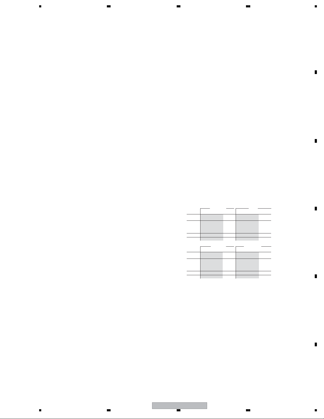
Tuner
Receivable channels
VHF (low)
VHF (high)
Hyper
UHF
VHF (low)
VHF (high)
Hyper
UHF
SECAM B/G
PAL B/ G
Frequency
47 MHz to 89 MHz
104 MHz to 300 MHz
302 MHz to 470 MHz
470 MHz to 862 MHz
SECAM L
Frequency
49 MHz to 65 MHz
104 MHz to 300 MHz
300 MHz to 470 MHz
470 MHz to 862 MHz
Channel
E2 to E4
X to Z
E5 to E12
S1 to S20
M1 to M10
U1 to U10
S21 to S41
E21 to E69
Channel
FB, FC1, FC
F1 to F6
B to Q
S21 to S41
21 to 69
PAL I
Frequency
44 MHz to 89 MHz
104 MHz to 300 MHz
302 MHz to 470 MHz
470 MHz to 862 MHz
SECAM D/K
PAL D/ K
Frequency
49 MHz to 94 MHz
104 MHz to 300 MHz
302 MHz to 470 MHz
470 MHz to 862 MHz
Channel
A to C
X to Z
D to J
11, 13
S1 to S20
S21 to S41
E21 to E69
Channel
R1 to R5
R6 to R12
S1 to S20
S21 to S41
E21 to E69
STEREO
B/G - A2
I - NICAM
L - NICAM
B/G - NICAM
D/K - NICAM
A
B
C
D
E
56
DVR-640H-AV
F
5
7
8
Page 6

1234
Input/Output
VHF/UHF antenna input/output terminal
A
B
C
D
. . . . . . . . . . . . . . . .VHF/UHF set 75Ω (IEC connector)
Video input . . . . . . . . . . . . . . . . . . . . . . . . . Input 2 (front)
Input level . . . . . . . . . . . . . . . . . . . . . . . . . . 1 Vp-p (75Ω)
Jacks . . . . . . . . . . . . . . . . . . . . AV connector 2 (Input 1),
Video output . . . . . . . . . . . . . . . . . . . . . . . . . AV1, Output
Output level . . . . . . . . . . . . . . . . . . . . . . . . 1 Vp-p (75Ω)
Jacks . . . . . . . . . . . . . . . . . . . . . . . . AV connector (AV1)
S-Video input . . . . . . . . . . . . . . . . . . . . . . . Input 2 (front)
Y (luminance) - Input level . . . . . . . . . . . . . 1 Vp-p (75Ω)
C (colour) - Input level . . . . . . . . . . . . . 300 mVp-p (75Ω)
Jacks . . . . . . . . . . . . . . . . . . . . AV connector 2 (Input 1),
S-Video output . . . . . . . . . . . . . . . . . . . . . . . AV1, Output
Y (luminance) - Output level . . . . . . . . . . . . 1 Vp-p (75Ω)
C (colour) - Output level . . . . . . . . . . . 300 mVp-p (75Ω)
Jacks . . . . . . . . . . . . . . . . . . . . . . AV connector 1 (AV1),
Component video output
Output level . . . . . . . . . . . . . . . . . . . . . Y: 1.0 Vp-p (75Ω)
Jacks . . . . . . . . . . . . . . . . . . . . . . . . . . . . . . . RCA jacks
RGB input
Input level . . . . . . . . . . . . . . . . . . . . . . . . 0.7 Vp-p (75Ω)
Jacks . . . . . . . . . . . . . . . . . . . . AV connector 2 (Input 1)
RGB output
Output level . . . . . . . . . . . . . . . . . . . . . . . 0.7 Vp-p (75Ω)
Jacks . . . . . . . . . . . . . . . . . . . . . . AV connector 1 (AV1)
Audio input . . . . . . . . . . . . . . . . . . . . . . Input 2 (front) L/R
Input level
During audio input . . . . . . . . . . . . . . . . . . . . . . . 2 V rms
(Input impedance: more than 22 kΩ)
Jacks . . . . . . . . . . . . . . . . . . . .AV connector 2 (Input 1),
Audio output . . . . . . . . . . . . . . . . . . . . . . . . . AV1, Output
During audio output . . . . . . . . . . . . . . . . . . . . . . 2 V rms
(Output impedance: less than 1.5 kΩ)
Jacks . . . . . . . . . . . . . . . . . . . . . . AV connector 1 (AV1),
Control input . . . . . . . . . . . . . . . . . . . . . . . . . . . .Mini jack
Digital audio ouptut . . . . . . . . . . . . . . . . . . . . . . . Coaxial
G-LINK™ . . . . . . . . . . . . . . . . . . . . . . . . . . . . . . Mini jack
RCA jack (Input 2)
RCA jack (Output)
4 pin mini DIN (Input 2)
4 pin mini DIN (Output)
P
, PR: 0.7 Vp-p (75Ω)
B
RCA jacks (Input 2)
RCA jacks (Output)
AV Connectors (21-pin connector assignment)
AV connector input/output . . . . . . . . 21-pin connector
This connector provides the video and audio signals
for connection to a compatible colour TV or monitor.
PIN no. AV1(RGB)-TV / AV2(INPUT 1)
1. . . . . . . . . . . . . . . . . . . . . Audio 2/R out / Audio 2/R out
2 . . . . . . . . . . . . . . . . . . . . . . . . . . . . . . . - / Audio 2/R in
11 . . . . . . . . . . . . . . . . . . . . . . . . . . . . . . . . . . G out / G in
3 . . . . . . . . . . . . . . . . . . . . . Audio 1/L out / Audio 1/L out
6 . . . . . . . . . . . . . . . . . . . . . . . . . . . . . . . .- / Audio 1/L in
15 . . . . . . . . . . . . . . . . . . . . . . . . . . R or C out / R or C in
4. . . . . . . . . . . . . . . . . . . . . . . . . . . . . . . . . . . . . . . . .GND
17. . . . . . . . . . . . . . . . . . . . . . . . . . . . . . . . . . . . . . . .GND
7 . . . . . . . . . . . . . . . . . . . . . . . . . . . . . . . . . . . B out / B in
19 . . . . . . . . . . . . . . . . . . . Video out or Y out / Video out
20. . . . . . . . . . . . . . . . . . . . . . . . . . . . . - / Video in or Y in
8. . . . . . . . . . . . . . . . . . . . . . . . . . . . . . . . . . . . . . . Status
21. . . . . . . . . . . . . . . . . . . . . . . . . . . . . . . . . . . . . . . .GND
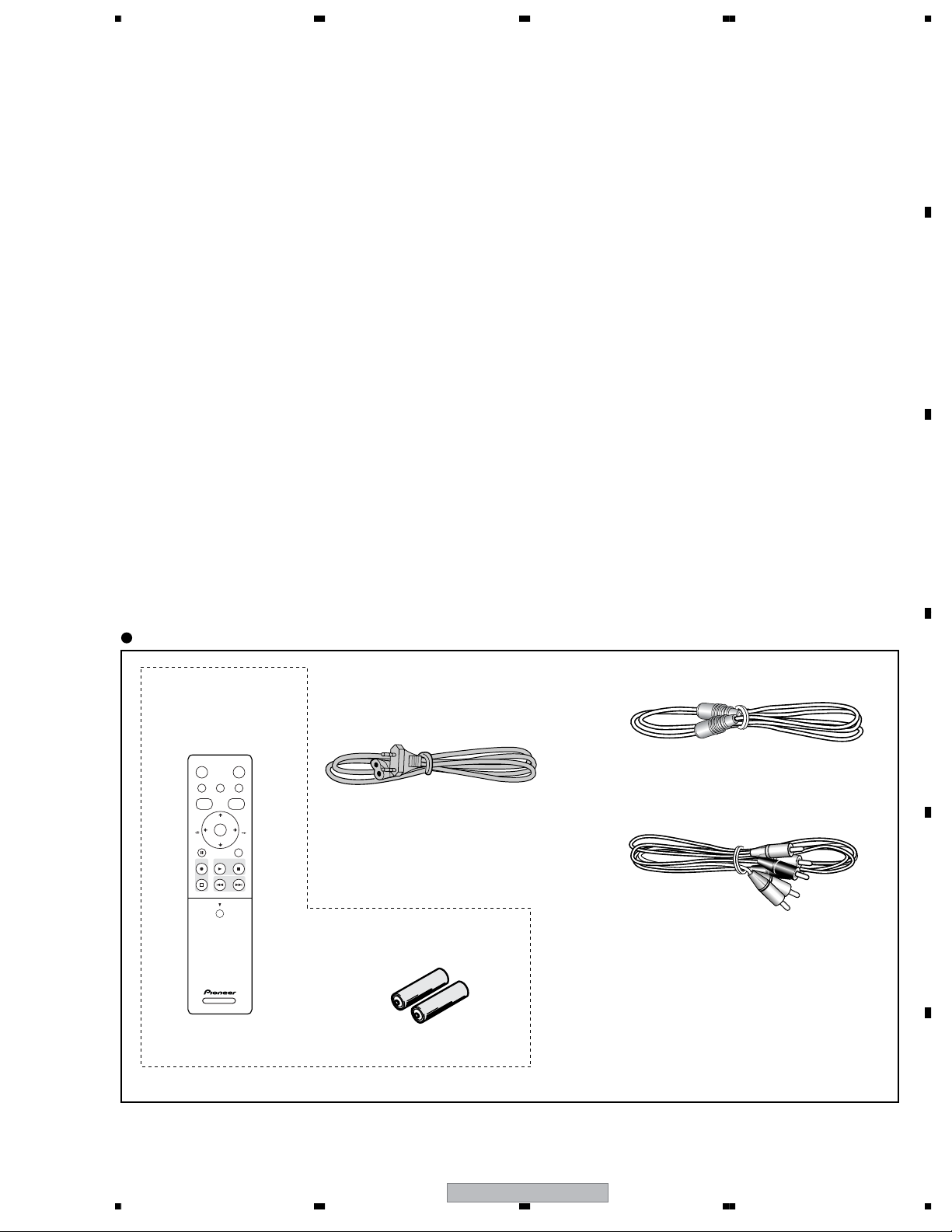
Supplied accessories
Remote control . . . . . . . . . . . . . . . . . . . . . . . . . . . . . . . . 1
Dry cell batteries (AA/R6P) . . . . . . . . . . . . . . . . . . . . . . 2
Audio / Video cable (red/white/yellow) . . . . . . . . . . . . . . 1
G-LINK™ cable . . . . . . . . . . . . . . . . . . . . . . . . . . . . . . . .1
RF antenna cable . . . . . . . . . . . . . . . . . . . . . . . . . . . . . . 1
Power cable . . . . . . . . . . . . . . . . . . . . . . . . . . . . . . . . . . .1
Operating Instructions
Warranty card . . . . . . . . . . . . . . . . . . . . . . . . . . . . . . . . . 1
Note: The specifications and design of this product are
subject to change without notice, due to improvement.
This product includes FontAvenue® fonts licenced
by NEC corporation. FontAvenue is a registered
trademark of NEC Corporation.
E
F
6
1234
DVR-640H-AV
Page 7
5678
A
B
Accessories
Except DVR-640H-AV
• Remote control ×1
(VXX3129)
STANDBY/ON
HDD/DVD
PAUSE LIVE TV HOME MENU INFO
TOP MENU
DISC
GUIDE
NAVIGATOR
CHANNEL
+
ENTER
PAUSE RETURN
CHANNEL
-
PLAYREC STOP
PREV NEXT
OPEN
CM
SKIP
CM
BACK
STOP REC
• Power cable ×1
(ADG1127 : WYXK5, WYXV5,
WYXVRE5 types)
• Dry cell batteries ×2
(AA/R6P)
C
• RF antenna cable(PAL) ×1
(VDE1075)
D
• Audio / Video cable(1.5m) ×1
(red/white/yellow)
(VDE1077)
E
• G-Link Cable (3m) ×1
(VDX1010)
DVD RECORDER
DVR-640H-AV
56
F
7
7
8
Page 8
1234
2. EXPLODED VIEWS AND PARTS LIST
NOTES:
Parts marked by "NSP" are generally unavailable because they are not in our Master Spare Parts List.
The mark found on some component parts indicates the importance of the safety factor of the part.
A
Therefore, when replacing, be sure to use parts of identical designation.
Screws adjacent to mark on product are used for disassembly.
For the applying amount of lubricants or glue, follow the instructions in this manual.
(In the case of no amount instructions, apply as you think it appropriate.)
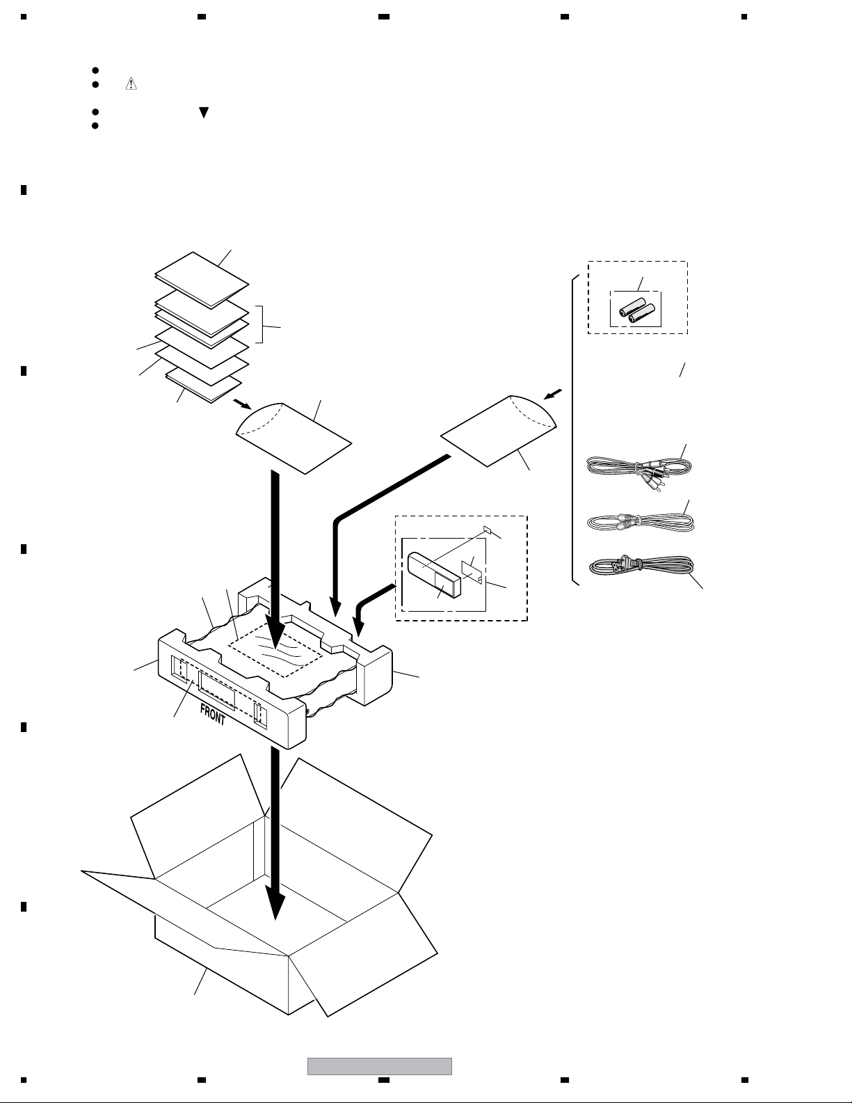
2.1 PACKING
B
(DVR-540H-S
/WYXVRE5
only)
C
27
(DVR-540H-S/WYXVRE5
26
only)
20 to 24
(DVR-540H-S/WYXK5
and WYXV5 types
9
6
only)
7
5
Except
DVR-640H-AV models
18
4
3
2
14
16
8
13
D
10
19
(for door protect)
E
17
Except
DVR-640H-AV models
11
15
1
F
8
1234
12
DVR-640H-AV
Page 9
>
>
5678
(1) PACKING SECTION PARTS LIST
No. Description Part No.
Mark
1Power Cord See Contrast table (2)
2 RF Antenna Cable (PAL) VDE1075
3Audio/Video Cable (1.5m) VDE1077
4 G-Link Cable (3m) VDX1010
5Polyethylene Bag B5 VHL1088
NSP 6 Warranty Card ARY7065
7Polyethylene Bag See Contrast table (2)
NSP 8 HDD Caution 8L B See Contrast table (2)
NSP 9 HDD Caution 8L See Contrast table (2)
10 Front Pad See Contrast table (2)
11 Rear Pad See Contrast table (2)
12 Packing Case See Contrast table (2)
13 Mirror Sheet See Contrast table (2)
14 WEEE Label See Contrast table (2)
15 Remote Control Unit See Contrast table (2)
16 Battery Cover See Contrast table (2)
No. Description Part No.
Mark
17 Top Cover See Contrast table (2)
NSP 18 Dry Cell Battery (R6P, AA) See Contrast table (2)
19 Mirror Sheet VHL1104
20 Operating Instructions See Contrast table (2)
21 Operating Instructions See Contrast table (2)
22 Operating Instructions See Contrast table (2)
23 Operating Instructions See Contrast table (2)
24 Operating Instructions See Contrast table (2)
25 Operating Instructions See Contrast table (2)
26 Operating Instructions See Contrast table (2)
27 EPG Caution Card See Contrast table (2)
A
B
(2) CONTRAST TABLE
DVR-640H-AV/WYXK5, WYXV5, DVR-540H-S/WYXK5, WYXV5 and WYXVRE5 are constructed the same except
for the following:
Mark No. Symbol and Description
1Power Cord ADG1127 ADG1127 ADG1127 ADG1127 ADG1127
7Polyethylene Bag VHL1051 VHL1088 VHL1051 VHL1088 VHL1088
NSP 8 HDD Caution 8L B VRR1046 VRR1062 VRR1046 VRR1062 VRR1062
NSP 9 HDD Caution 8L VRR1047 VRR1063 VRR1047 VRR1063 VRR1063
10 Front Pad VHA1404 VHA1415 VHA1404 VHA1415 VHA1415
11 Rear Pad VHA1405 VHA1416 VHA1405 VHA1416 VHA1416
12 Packing Case VHG2719 VHG2757 VHG2698 VHG2683 VHG2734
13 Mirror Sheet VHL1107 VHL1095 VHL1107 VHL1095 VHL1095
14 WEEE Label Not used Not used VRW2231 VRW2231 VRW2231
15 Remote Control Unit Not used Not used VXX3129 VXX3129 VXX3129
16 Battery Cover Not used Not used VZN1004 VZN1004 VZN1004
17 Top Cover Not used Not used VZN1009 VZN1009 VZN1009
NSP 18 Dry Cell Battery (R6P, AA) Not used Not used VEM1010 VEM1010 VEM1010
20 Operating Instructions (French) Not used Not used VRC1320 VRC1320 Not used
21 Operating Instructions (German) Not used Not used VRC1321 VRC1321 Not used
DVR-640H-AV
/WYXK5
DVR-640H-AV
/WYXV5
DVR-540H-S
/WYXK5
DVR-540H-S
/WYXV5
DVR-540H-S
/WYXVRE5
C
D
E
22 Operating Instructions (Italian) Not used Not used VRC1322 VRC1322 Not used
23 Operating Instructions (Dutch) Not used Not used VRC1323 VRC1323 Not used
24 Operating Instructions (Spanish) Not used Not used VRC1324 VRC1324 Not used
25 Operating Instructions (English) Not used Not used Not used Not used Not used
26 Operating Instructions (Russian) Not used Not used Not used Not used VRC1333
27 EPG Caution Card Not used Not used Not used Not used VRR1066
DVR-640H-AV
56
7
F
9
8
Page 10
1234
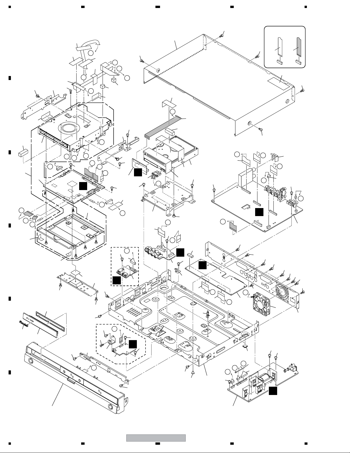
2.2 EXTERIOR SECTION
46
56
46
46
E b
E a
B a
A
51
34
46
46
46
39
I b
B b
39
I a
54
33
54
46
54
NON-CONTACT
SIDE
CONTACT SIDE
47
54
B
41
40
10
11
4
C
K
L
M
46
Reuse (*) marked
parts when exachanging
D
Service LOADER
Assy.
• Silicon Sheet R9B
(DEB1726) x3
• Case Screw S
(DBA1250) x2
• Frontboard Screw
R7C
(DBA1220) x2
43
E
45
(1/2)
44
(*)
E b
(*)
52
M
L
52
(*)
(*)
(*)
46
DVR-640H-AV
54
10
F
K
(2/2)
31
28
(*)
54
only
I a
15
52
35
J
46
H
I b
B b
J
(*)
37
52
52
54
57
27
A
52
7
52
52
46
D
DVR-640H-AV
only
E a
52
19
H
B a
6
14
52
G
5
54
I
30
C
36
16
52
40
54
H
18
9
42
56
42
55
F
52
A
32
52
F
54
C
52
3
26
54
23
17
21
B
25
17
O
C
52
G
1
P
D
N
22
38
13
54
53
A
O
N
53
52
53
52
12
20
29
P
52
G
2
53
54
53
53
56
24
J
F
10
Refer to
"2.3 FRONT PANEL SECTION".
DVR-640H-AV
1234
8
Page 11

>
5678
(1) EXTERIOR SECTION PARTS LIST
No. Description Part No.
Mark
1 SCRB Assy VWV2206
2 TUJB Assy (for service) See Contrast table (2)
3 FJKB Assy (for service) VXX3113
4 MAIN Assy (for service) See Contrast table (2)
5DVJB Assy See Contrast table (2)
No. Description Part No.
Mark
31 Radiation Sheet (Silicone) VEB1360
32 Rubber Spacer VEB1378
33 Bonnet VXX3105
NSP 34 Writer Stay L VNE2421
NSP 35 Writer Stay R VNE2422
A
6 USBB Assy See Contrast table (2)
7 ATAB Assy (for service) VXX3140
8POWER SUPPLY Unit VWR1399
9 HDD 160GB ST3160022RS VXF1086
10 LOADER Assy (for service) VXX3156
NSP 11 Service LOADER MAIN See Contrast table (2)
12 Connector Assy PF05PP-S07
13 Connector Assy PF13PP-S22
14 Flexible Cable 24P See Contrast table (2)
15 Flexible Cable 40P VDA2112
16 Flexible Cable 23P VDA2115
17 Flexible Cable 29P VDA2117
18 Flexible Cable 35P VDA2118
19 Housing USB (MAIN) See Contrast table (2)
20 DC Fan Motor 60 VXM1125
21 PCB Support AEC1215
22 Rubber Foot VEB1349
NSP 23 PC Support VEC1749
24 Rear Panel See Contrast table (2)
NSP 25 Chassis VNB1055
NSP 26 PCB Base VNE2378
27 DV Angle See Contrast table (2)
NSP 28 Bridge VNE2429
29 Earth Plate TU VBK1162
30 Housing Assy 4P VKP2357
NSP 36 HDD Stay VNE2423
37 Heatsink VNH1077
NSP 38 Binder (BK-1) ZCA-BK1
39 Rubber Spacer B VEB1380
40 Gasket 30 x 10T VEC2522
41 Aluminum Tape 25 x 25 VEF1060
42 Aluminum Tape 180 x 25 VEF1065
43 Pioneer Name Plate VAM1148
44 Tray Sheet VEC2500
45 Tray Panel VNK5910
NSP 46 Tape ZTA-156A-19
47 Laser Caution Label VRW2262
48 • • • • •
49 • • • • •
50 • • • • •
51 Screw AMZ30P040FTC
52 Screw BBZ30P060FTC
53 Screw BPZ30P080FTC
54 Screw BSZ30P040FTC
55 #6-32 Screw DBA1125
56 Screw PBZ30P080FTC
57 Screw M3 x 8 See Contrast table (2)
B
C
D
(2) CONTRAST TABLE
DVR-640H-AV/WYXK5, WYXV5, DVR-540H-S/WYXK5, WYXV5, WVXK5 and WYXVRE5 are constructed the same
except for the following:
Mark No. Symbol and Description
2 TUJB Assy (for service) VXX3109 VXX3109 VXX3108 VXX3108 VXX3108
4 MAIN Assy (for service) VXX3157 VXX3157 VXX3159 VXX3159 VXX3159
5DVJB Assy VWV2160 VWV2160 Not used Not used Not used
6 USBB Assy VWV2161 VWV2161 Not used Not used Not used
NSP 11 Service LOADER MAIN VXU1001 VXU1001 VXU1002 VXU1002 VXU1002
14 Flexible Cable 24P VDA2111 VDA2111 Not used Not used Not used
19 Housing USB (MAIN) VKP2380 VKP2380 Not used Not used Not used
24 Rear Panel VNA2903 VNA2931 VNA2894 VNA2916 VNA2915
27 DV Angle VNE2426 VNE2426 Not used Not used Not used
57 Screw M3 x 8 VBA1088 VBA1088 Not used Not used Not used
56
DVR-640H-AV
/WYXK5
DVR-640H-AV
/WYXV5
DVR-640H-AV
DVR-540H-S
/WYXK5
7
DVR-540H-S
/WYXV5
DVR-540H-S
/WYXVRE5
8
E
F
11
Page 12
1234
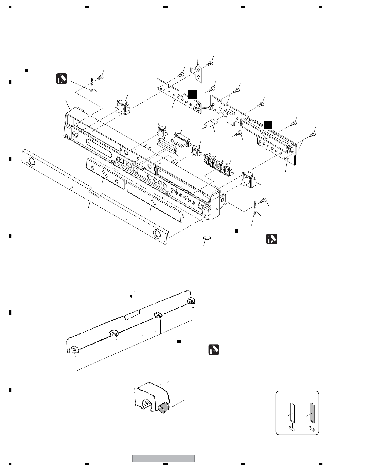
2.3 FRONT PANEL SECTION
A
Lubricant
Hanarl
GEM1041
12
16
4
10
(1/2)
16
5
16
16
E
16
16
2
14
7
13
9
FJKB
CN7302
3
7
16
11
4
10
D
(2/2)
16
B
8
C
15
16
16
1
Lubricant
Hanarl
6
D
GEM1041
Door Shaft
Lubricant
E
F
12
1234
to Door Shaft
DVR-640H-AV
Hanarl
GEM1041
Paste lubricant hanarl (GEM1041)
to salient points of both side of the
door.
NON-CONTACT
SIDE
CONTACT SIDE
Page 13
5678
(1) FRONT PANEL SECTION PARTS LIST
No. Description Part No.
Mark
1 FLKY Assy (for service) VXX3111
2 KEYB Assy (for service) VXX3112
3 Flexible Cable 12P VDA2116
4 Door Spring VBK1159
5 Earth Plate VBK1166
6 Rubber Foot VEB1349
7 Sub Key VNK5909
8 Center Cover VNK5911
9 LED Lens VNK5913
10 Main Key See Contrast table (2)
A
11 Function Key VNK5936
12 Front Panel See Contrast table (2)
13 Center Key See Contrast table (2)
14 FL Lens PTD See Contrast table (2)
15 Door PTD See Contrast table (2)
16 Screw BPZ30P080FTC
(2) CONTRAST TABLE
DVR-640H-AV/WYXK5, WYXV5, DVR-540H-S/WYXK5, WYXV5, WVXK5 and WYXVRE5 are constructed the same
except for the following:
Mark No. Symbol and Description
10 Main Key VNK5925 VNK5925 VNK5908 VNK5908 VNK5908
12 Front Panel VNK5957 VNK5957 VNK5923 VNK5923 VNK5923
13 Center Key VNK6026 VNK6026 VNK6025 VNK6025 VNK6025
14 FL Lens PTD VXA2741 VXA2741 VXA2740 VXA2740 VXA2740
15 Door PTD VXA2775 VXA2775 VXA2774 VXA2774 VXA2774
DVR-640H-AV
/WYXK5
DVR-640H-AV
/WYXV5
DVR-540H-S
/WYXK5
DVR-540H-S
/WYXV5
DVR-540H-S
/WYXVRE5
B
C
D
56
DVR-640H-AV
E
F
13
7
8
Page 14
1234
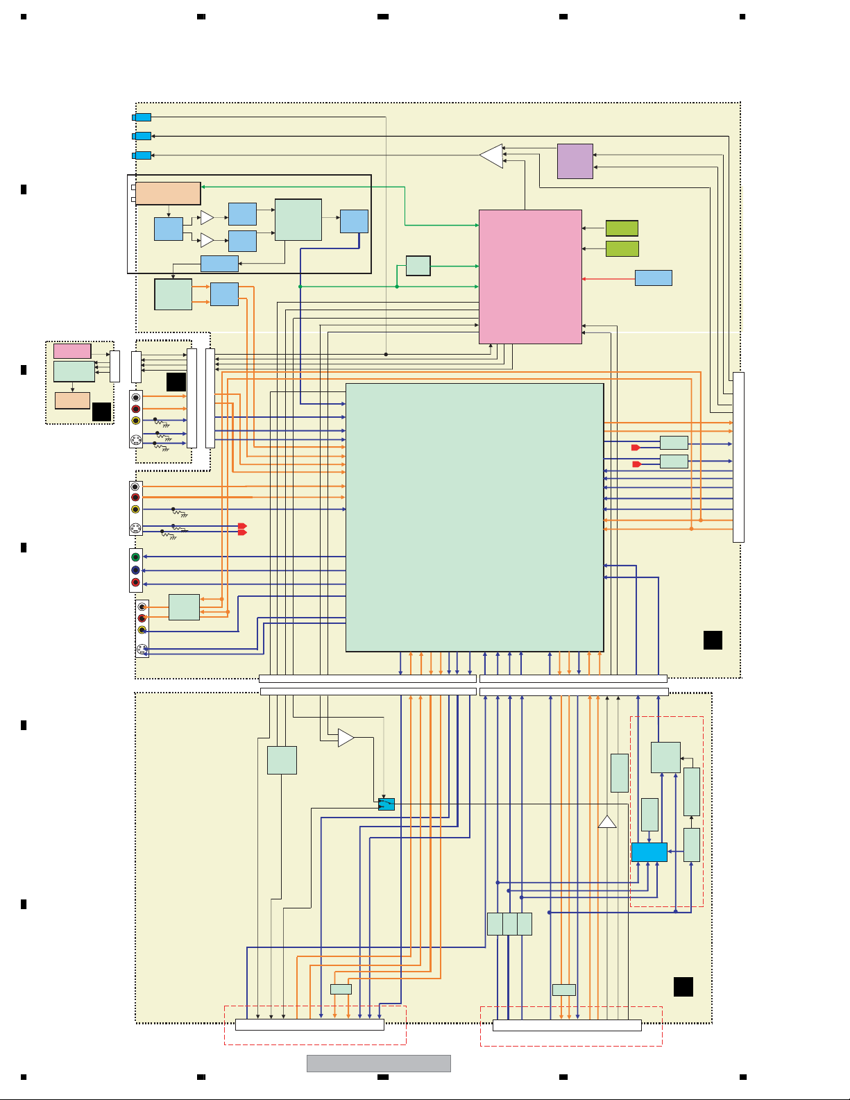
3. BLOCK DIAGRAM AND SCHEMATIC DIAGRAM
3.1 BLOCK DIAGRAM
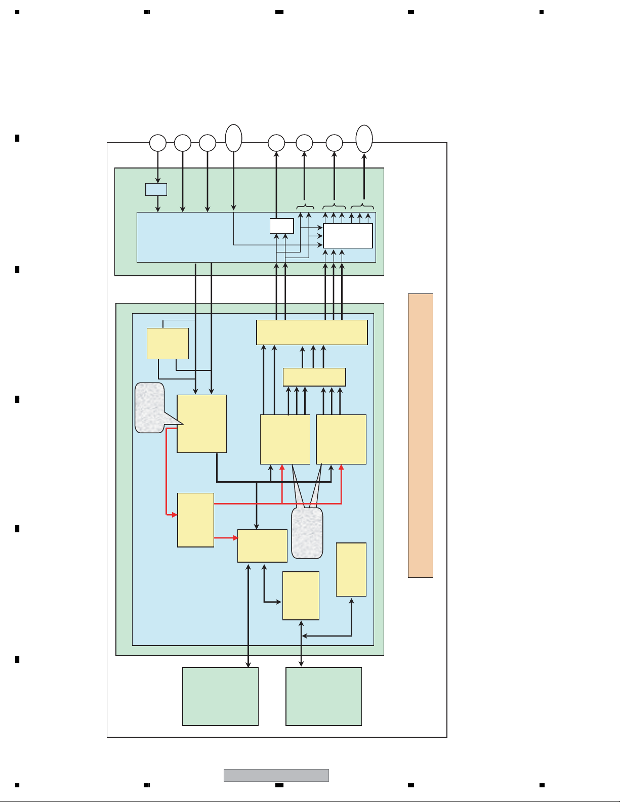
3.1.1 OVERALL BLOCK DIAGRAM
A
SEL_IR
OPTICAL
IR Blaster
VHF/UHF Tuner
IF Trap
B
IR Receiver
FL DRIVER
FL TUBE
FLKY
C
6
4
3
2
CN7001
D
INPUT 2
JA2010
COMPONENT
OUT
JA2001
7
9
10
11
JA7302
CN7302
Multisound
Decoder
FJKB
Y
Cb
Cr
Filter
C
CN7301
MUTE
18
20
21
22
9
11
7
5
1
PIF AMP
SIF AMP
4.5 - 6.7MHz
SIF BPF
LPF
CN101
6
4
3
2
15
13
17
19
23
SAW
Filter
SAW
Filter
D
OUTPUT
SEL_IR
Blaster
mic
PDF015A
Single/multista
ndard VIF/SIF-
PLL and FM-
PLL/AM
demodulators
BS IN
RGBOUT
V2
Y2C27
TU-L
TU-R
L2-L
L2-R
L3-L
L3-R
V3
Y3
C3
VOUT2
YOUT2
COUT2
CN604
28 1816 22 20 21 29 10 8 4 2 1224 26 2 8 1016 18 22 28 4 6 26 25 24 20 14
CN1
5.5M
Trap
Filter
Tuner
IR
FLDATA
FLCLK
FLSTB
18
14
9
87
86
92
91
85
84
20
40
39
38
32
36
34
VOUT1
SCL/SDA
27.28
81
TEXTV
6dBAMP
SYNCAFT
FUNC_ON
SQU
XAVLTH
AVLIN
AVLOU
306
94 93
44 46 16
73 74
L1R
L1L
L1R
L1L
GR/CB
Tuner Control U-CON
67
41
42
48
70 22
26
7123
RENESAS
HA118326PF
45
VIN1
49 48 50L312
G
71
BR/C
AV2LAV2RAV
72
12.13
10MHz
10.9
32.768k
BATTDEC
21
72
FUNC_IN
BLANK
80
79
61
59
55
57
51
53
52
76
1
100
BATT
4
1
2
3
AL
32
AR
CN4002
34
28
30
19
17
21
23
25
15
13
V/Y
MM1503
Y3
C
MM1501
C3
Y
C
Y/G
Cb/B
Cr/R
77
AL
AR
RGB_YIN
A
22
90
89
AV
AV
2R
2L
2V
CN605
CN2
TUJB
MUTE
AV1
B
B
G
R/C
R/C
GB
V/Y
DVR-640H-AV
LPF
BUF
LPF
Volt
age
chan
ge
B
LPF
BU
BUF
F
MUTE
V
2V/Y
BR/C G
Blank
FUNC
AV2
JA802JA801
BH7326AF
AV_LINK
Crystal
1201
VSS
FU
TC4W53
B
SCRB
TC74HC123AF
LA7213
Voltage
change
E
F
1V/Y
Blank AV_LINK
FUNC
INPUT1/OUTPUT1 INPUT3
14
1234
Page 15
_TO_
5
/
,
20
25
28
30
26
27
29
9
8
6
15
13
11
17
19
21
23
1
32
4
2
CVBS/Y
CN2301
5678
A
(DVR-640H-AV
Only)
USB
1,2
3,4
6- 11
1,2
47,48
49,50
35,37
24,25,
33,34
WRITER
ATAB
B
C
HDD
D
P_CONT2
MRST
XRESET
DA T_TO_M
HS T
X525P
C
Yp
Cb
Cr
Y
C
L
R
ZEROR
buffer
L
R
CN5601
U2,V2
F1,G1
N21
B1,C1
N2
P2
P3
K2
M1
P2
IC5701
USB control IC
TDOTG242-
0F0C8
N1
P1
N3
SL1
SL2
MDRV
LO
FDRV
TDRV
FE
TE
RFEQO
95,96
512M SDRAM
K4H511638C-
512M SDRAM
K4H511638C-
28
29
24
26
53
52
87
85
uPC3345GC
16MHz
X1001
24MHz
X1002
27MHz
IC1201
UCB3
IC1221
UCB3
IC501
FTS driver
BD7997FS
IC101
RF IC
-YEB
X201
IC1102
64M FLASH
S29GL064M90TCI
R30
voltage
regulator
B7
V21
U17
N20
U21
R21
W15
W21
M17
N18
UPD61272F1-
C8
EMMA2RFE
C7
D6
C9
D10
B9
C10
D11
R18
A9
V15
C11
B6
A7
A6
B10
T20
External ROM I/F
DDR SDRAM I/F
IC1001
107KA3A
INT*2/U ART*2/
IC3707
RESET IC
SS T to M
IC3701
M
USBRST
IC2201
SW IC
MM1503XN
IC2202
SW IC
MM1501XN
IC3202
IC3101
audio ADC
AK5359ET
IC3102
TC7SZ126
IC3201
audio DAC
PCM
1742KE
IC3103
SELECT IC
TV74VHC15
7FT
5V to 3V
HS M to T
ASCK_NSCK
X525P SCL
USBRST SDA
buffer
buffer
buffer
buffer
buffer
buffer
buffer
BCKO
LRCKO
ADATAO
NSCS
DACCLKO
ADATAI
BCKI
LRCKI
ADCCLKO
AD POW
HS T to M
AMUTE
SPDIFO
CN101
36,37
34,35
1- 6
49,50
45,46
47,48
USBB
2,3
7-
10
H
ST1+/ST2+/-
CN502
SPDL
CN501
LOAD+/-
CN601
F+, FT+, T-
RF+, RF-
A- D
CN101
CN3801
DV LRCKI
12
PHY
DV LRCKI
IC 3802
Expand IO
PCA9557
PW
INT*2/U ART*2
21,20
4,5
INT*2/U ART*2/
DVout
DV_XADC
AD POW
F
MAIN
E
18,1711
7,8
(DVR-640H-AV
G
DVJB
Only)
F
DVR-640H-AV
7
8
15
SCL
SDA
USBRST
525P
DVRST
SCL
SDA
DV C I N
AMCLKI(STBY)
CN3802
CN101
DV Y/ V IN
7
3
1
22 24 10 11
18
6
SCL
SDA
DVRST
VENC IC
IC101
ADV7172KSTZ-K
LINK/DVCODEC
IC102
UPD72893BF1-FN3-K
16M SDRAM
IC103
K4S161622H-TC60-K
1 15
DV Y/ V IN
DV C I N
V ADATA I
DV BCKI
D
14 1319 6
14
ATA I
(STBY)
I
DV BCKI
AD
V
D
AMCLK
IC108
UPD72852AGB-8EU
56
Page 16
DIGITAL UNIT
CYPb
Pr
Y
C
TV TUNER UNIT
Module
1234
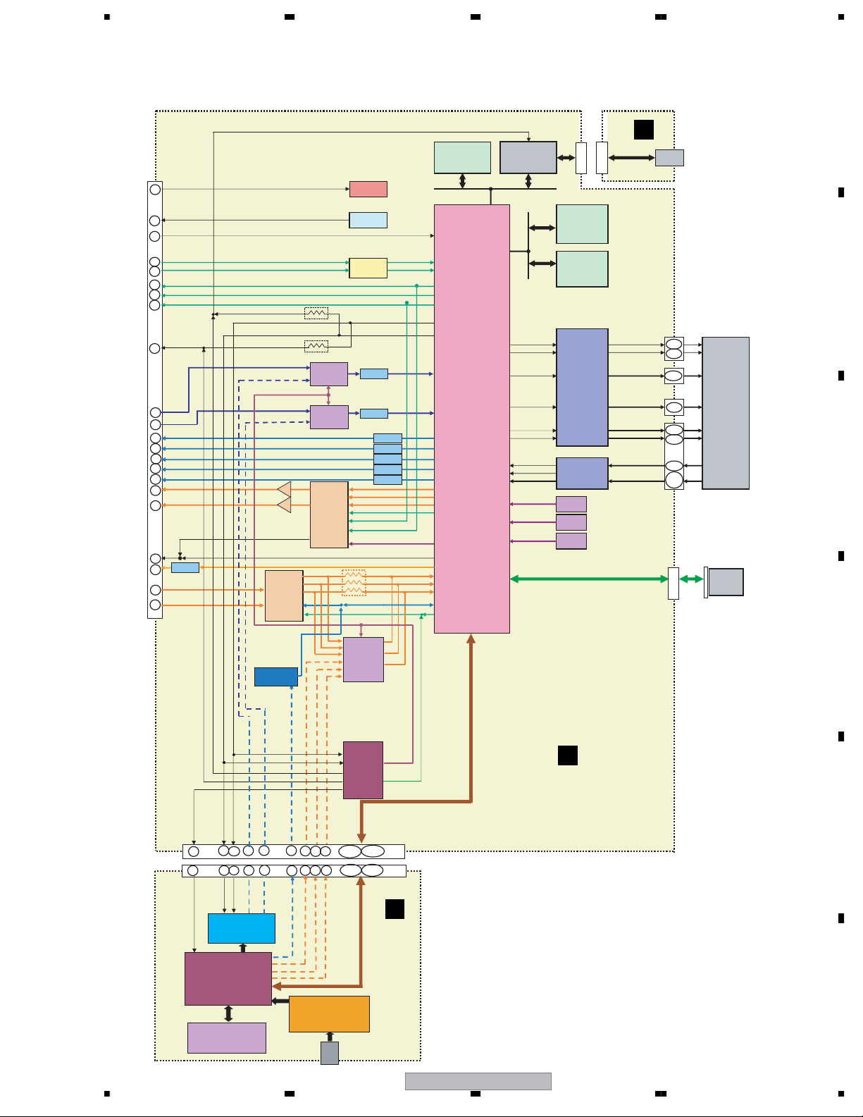
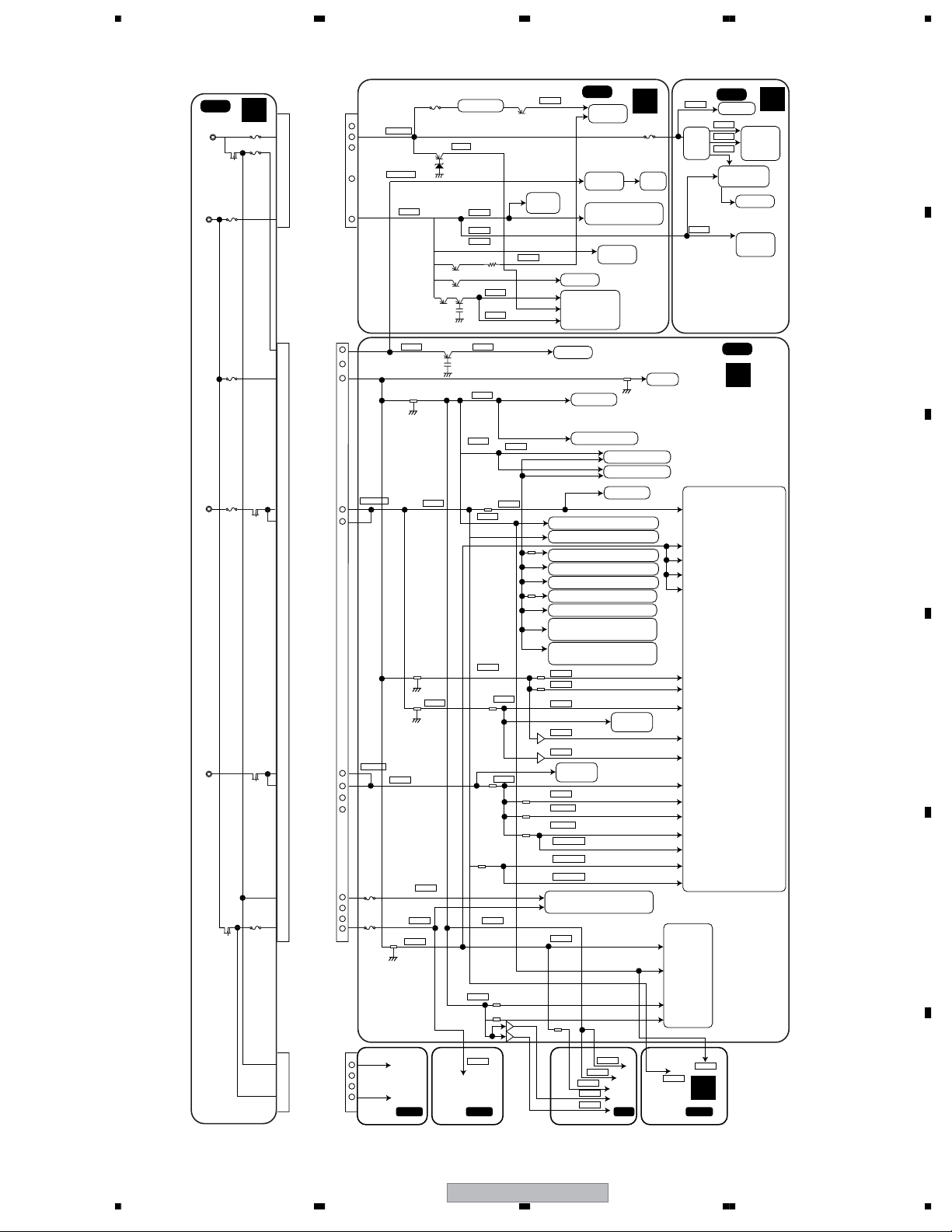
3.1.2 DETECTION AND ENCODE SYSTEM BLOCK DIAGRAM
A
/RGB IN
(Euro Scart)
ANTENNA IN
CVBS IN
S-Video IN
Tuner
Module
Input
Selector
&
Driver
Output
&
Euro
Scart
Interface
IC
B
TV TUNER UNIT
CVBS/S-Video
CVBS OUT
S-Video OUT
YC
MIX
YPbPr OUT
( 525I / 525P )
Euro
Scart
Inter
face
/RGB OUT
(Euro Scart)
Pb
R
Pb/B
Block
Video
Encoder
Progressive
C
Y/C
Sep.
Block
C
Y
Detection
Block
D
DIGITAL UNIT
Detected Result
C
CVBS
/Y
Block
Video Decoder
Y,U,V
REC.656
DAC
Video
Interlace
Block
I/P
Video
Sel.
Block
Encoder
PAL Model Block Diagram
Block
Micro-
Controller
Enc.
/Dec.
MPEG
E
SystemLSI
uPD61272
Data
Recording Control
Block
Insertion
Encoder
Enc/Dec
CD/DVD
Block
Block
DSP
Encoder Control
Micro-
Controller
DVR-440H-S/DVR-540H-S/DVR-640H-S/DVR-440H-AV/DVR-640H-AV
: Refer to [05 DVR model list] No.A6-A17,A20-A26
Detection and Encode System Block Diaglam
&
(ASP
PickUp
HDD Unit
F
16
1234
DVR-640H-AV
DVD Unit
mecha)
Page 17
5678
3.1.3 POWER BLOCK
SYPS
P201A
P204A
P501A
J
P401A
P402A
P202A
CN202 CN303
5
P_ON
4
EV+12.1V
3
GND
1
GND
2
EV+5.8V(T)
CN201 CN2401
5
EV+12.1V(J)
12
GND
13
EV+5.8V(M)
7
SW+3.33V(M)
8
SW+3.33V(M)
10
SW+1.53V(M)
11
SW+1.53V(M)
6
GND
9
GND
1
SW+1.21V(W)
2
GND
3
GND
4
SW+5V(W)
SW+3.33V
V+1R5_IN
IC2401
IC2402
IC5001
V+12R1E
V+12R1SW
V+5R8E
V+12A
IC4504
V+3D
IC4511
IC4512
V+2R5
V+1R5
V+12M
V+5M V+5L
IC4507
V+3FE
DCDC Con
V+9V
V+5V
V+5F
V+5M
V+5A
V+12A
V+5AVI
V+5VI
V+5VO
V+3FE
V+5TU
Audio
MUTE
V+31V
SPDIF
Interface IC
Audio LPF
Video buffer
INPUT Video filter
TUJB
Tuner
U301
FAN Circuit
RESET IC(Tu-con)
Tuner Con
IC100
IC102
IC101
IC5621
Audio DAC
A
IC1001
FAN
USB
IC3201
FLKY
V+12V
FLDC+
DC
FLDC-
DC
FL-28V
Con
BLUE LED
FL DRIVER
IC7001
FL TUBE
V7001
D
A
RED LED
V+5F
Infrared
Sensor
SW
B
MAIN
F
Audio ADC IC3101
3R3V
V+5D
RS-232C
FLASH IC1102
EJTAG
TC7SU04FU
IC3102
TC74VHC157FT IC3103
IC3701
TC7WH34FU
IC5701
USB driver
EMMA
for I/O_buffer
IC1001
M3, AD/DA/WBLSLICE
V2, EFMPLL/EFMCOMP
Y7, LVDS
Y8, APLL/DLYLINE/WCDLL
C
SPDIF
EMMA_Video_Decorder
External Filter
Pull-up for interface with Eriter,HDD
V+3V
V+DDR
1R5V
(ATA)
V_ADC
V_VENC
2R5V
VREF_V
VREF_D
RESET IC
IC3707
PVDD
VP VDD
V(DSP)
V_WP1(DSP)
V+3A(DSP)
V+3D(DSP)
6ch MOTOR DRIVER
V+3A
Video_Decorder_ADC
Video_Encorder
DDR x2
IC1201,IC1221
DDR_SDRAM
D
Video_DAC_Vref E8
DDR_VREF A15
Core E5,F5,J9,J13,N9,N13,U5,
U8,U14,U15
System_PLL D1
VDEC PLL J19,K19
R2,EFMPLL
AA10,WAPLL/DLYINE/WCDLL/
WRCHPLL/203MPLL
J20,VDEC HSCLAMP
L20,VDEC FSCLAMP
IC501
RF
IC101
REFI
E
Vcc6
V+5S
Vcc1,8,9
Vcc2,3,4,5,7
CN203
VD3V
VREF21
VREFFM
VA5V
VO5V
1
SW+12.1V(H)
2
GND
3
GND
4
SW+5V(H)
VCC
HDD P.U.
SPDL
DVR-640H-AV
56
V+5D
V+3D
G
DVJB
7
8
F
17
Page 18
1234
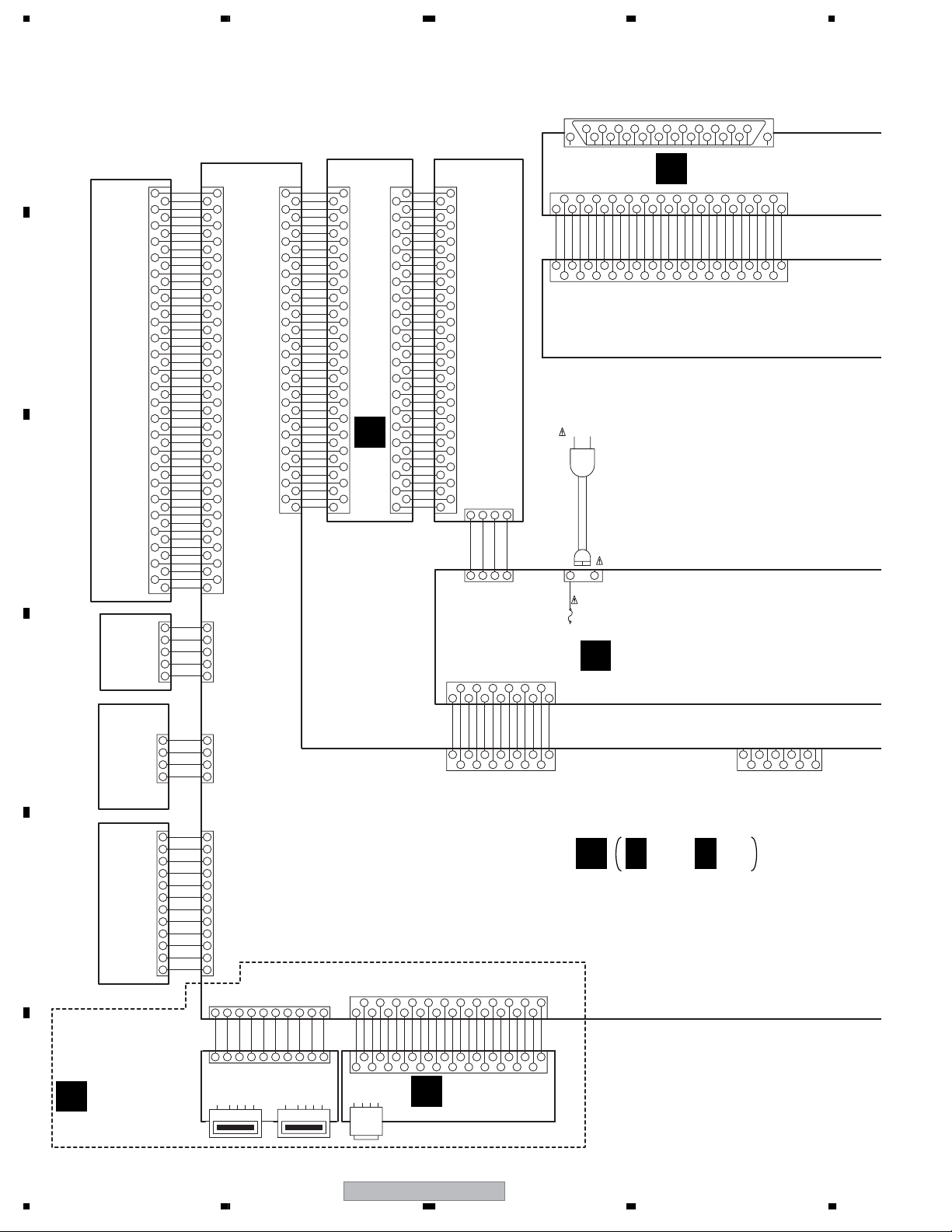
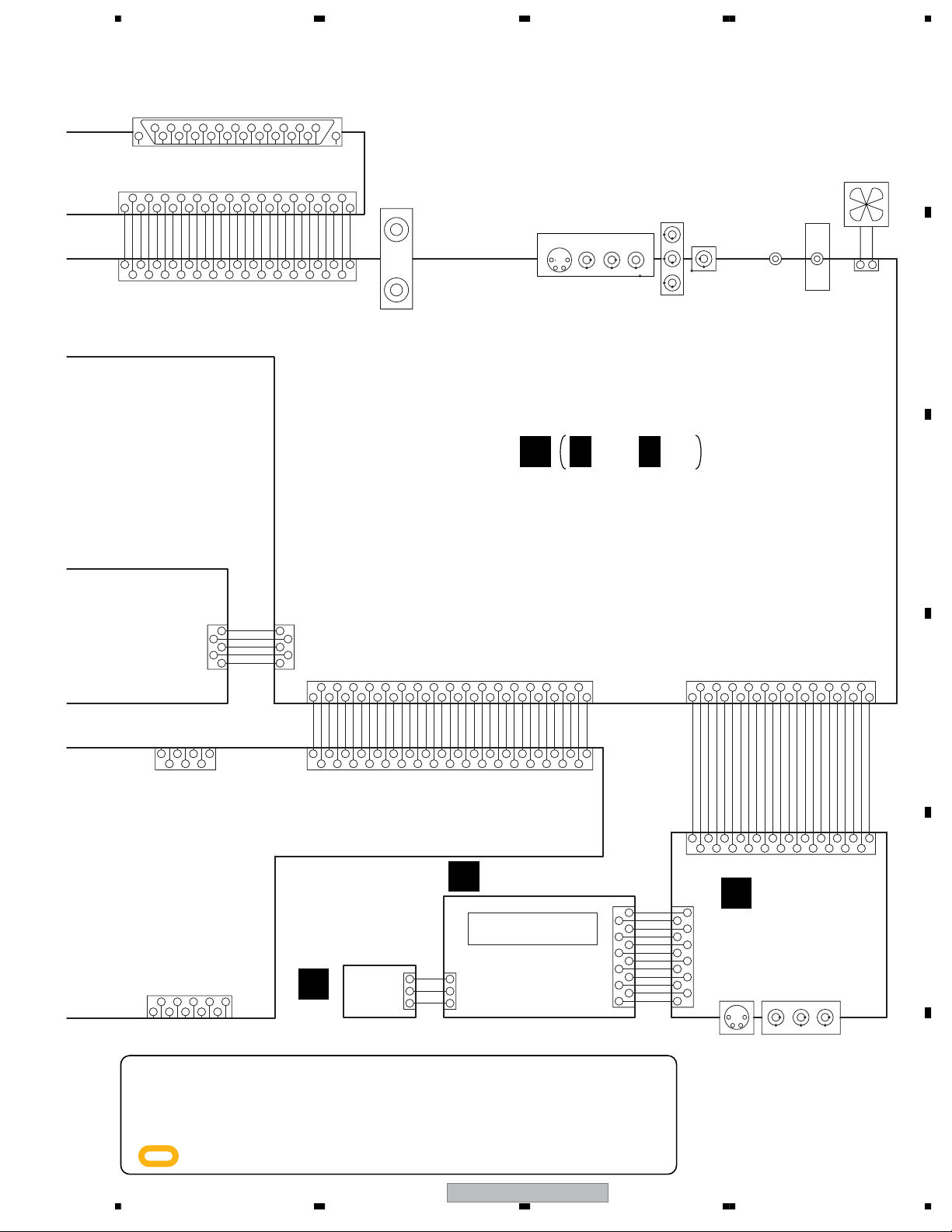
3.2 OVERALL WIRING DIAGRAM
A
JA801
CN101
TD
50
TR
49
49
FD
48
47
46
45
44
43
42
41
40
39
38
37
B
C
36
35
34
33
32
31
30
29
28
27
26
25
24
23
22
21
P. U.
20
19
18
17
16
15
14
13
12
11
10
9
8
7
6
5
4
3
2
1
5
4
3
2
1
FRONT
D
4
3
2
1
48
FR
47
SCLK
46
SEN
45
SDIO
44
VPP
43
RESET
42
RXW
41
VD3V
40
GNDD
39
TEMP
38
S1
37
S2
36
M1
35
M2
34
WRF
33
WPP2
32
VREFPD
31
WPP1
30
RF-
29
GNDS
28
RF+
27 17
VA5V
26
M3
25
M4
24
S3
23
S4
22
GNDS
21
VA5V
20
VREFFM
19
FMO
18
OSCEN-
17
OSCEN+
16
W3EN+
15
W3EN-
14
W2EN+
13
W2EN-
12
W1EN+
11
W1EN-
10
RDIS
9
W3SET
W2SET
7
W1SET
RSET
5
VO5V
VO5V
3
GNDO
GNDO
1
CN601
DKN1402-
LPS2
5
GNDD
4
LPS1
3
BLACK
2
RED
1
CN502
DKN1288-
ST2+
4
ST2-
3
ST1-
2
ST1+
1
CN3801
VKN2050-DKN1404-
4050
38
36
34
32
30
28
26
24
22
20
To HDD
18
16
14
12
10
8
6
4
2
8
6
4
2
CN11
VKN1818-
GND
DASP#
39 39
CS1#
CS0#
37
37
DA2
DA0
35
35
PDIAG#
DA1
33
33
RESERVED
INTRQ
31
31
GND
DMACK#
29
29
CSEL
IORDY
27
27
GND
DIOR#
25
25
GND
DIOW#
23
23
GND
DMARQ
21
21
KEYPIN
GND
19
19
DD15
DD0
17
DD14
DD1
15
15
DD13
DD2
13
13
DD12
DD3
11
11
DD11
DD4
9
9
DD10
DD5
7
7
DD9
DD6
5
5
DD8
DD7
3
3
GND
RESET#
11
40
38
36
34
32
30
28
26
24
22
20
18
16
14
12
10
8
6
4
2
CN12
VKN1816-
GND
1
DASP#
39
2
CS1#
3
CS0#
37
4
DA2
5
DA0
35
6
PDIAG#
7
DA1
33
8
RESERVED
9
INTRQ
31
10
GND
11
DMACK#
29
12
CSEL
13
IORDY
27
14
GND
15
DIOR#
25
16
GND
17
DIOW#
23
18
GND
19
DMARQ
21
20
KEYPIN
21
GND
19
22
DD15
23
DD0
17
24
DD14
25
DD1
15
26
DD13
27
DD2
ATAB ASSY(VXX3140)
I
13
28
DD12
29
DD3
11
30
DD11
31
DD4
32
34
36
9
DD10
33
DD5
7
DD9
35
DD6
5
DD8
37
DD7
3
38
GND
39
RESET#
1
40
40
38
36
34
32
30
28
26
24
22
20
18
16
14
12
10
8
6
4
2
SW+5V(H)
432211
CN204
CN201
12
13 11
GNDD
EV+5.8V
SW+1.53V
13 11
CN2401
S13B-PH-K-S
(160GB)
HDD
324
1
GND
GND
SW+12.1V(H)
CN101
10
SW+1.53V
10128246
46
82
531
7
9
GND
SW+3.33V
SW+3.33V
7
V+5M
GNDD
V+12V
531
GNDM
GNDD
9
1234567
GND
V+12M
Rin
Rout
3
1
2
22
VKB1157-
VKN1260-
CN1
GND
GND
GND
SAMUTE
AV1_R_OUT
AV1_L_OUT
3157
246
VKN1433- -TBB
CN604
AC POWER CORD
LIVE
(NEUTRAL)
J
Lout
FUNCTION
Bin
Lin
GNDV
GNDA
57
9
4
6
8
AV1(to TV)
12
8
13 192017
11109
GND
GND
GND
AV1_L_IN
AV1_R_IN
AV1_B_OUT
11
9
1081412161820
GNDV
10
N-LINK
B
V+12R1
BLANK
R/Cout
GNDV
GNDV
NC
Gout
111213
GNDV
GNDV
15
16
14
SCRB ASSY
(VWV2206)
161514
18
GND
SQU
GND
V+5V
AVL_IN
XAVLTH
AVL_OUT
FUNC_OUT
15 131719
212329 2527
GNDV
V/Yout
V/Yin
21171819
23
20
24
28
23212225 272629
GND
GND
GND
AV1_G_OUT
AV1_R/C_OUT
222428 26
BLANK_OUT
POWER SUPPLY UNIT
(VWR1339) or (VWR1400)
For EuDT
1236745
CN2601
VKN2038-
AV1_V/Y_OUT
9
8
10
STEPPER
CN501
DKN1312-
VCC
12
12
HU+
11
11
HU-
10
10
HV+
9
9
HV-
8
8
HW+
7
7
HW-
6
E
USBB ASSY
H
F
(VWV2161)
6
5
SPDL
4
3
2
1
HB
GNDD
U
V
W
5
4
3
2
1
CN5601
S10B-PH-K-S
10
USBDP1
10
CN101
B10B-PH-K-S
JA101
VKB1226-
6
GND
USBDM1
3
254
789645
GND
USBVFB
789645
1
7
V+5USB
JA102
6
1231
GND
GND
USBDM2
USBDP2
123
VKB1227-
5
47123
CN3802
VKN2045-
23456
GND
C_OUT
Y_OUT
242320
22
CN101
VKN2045-
2
3
GND
VENC_RST
21 19
JA101
VKN2028-
987
SCL
GND
SDA
V+3DV
17 15 11
18 16
G
DVR-640H-AV only
12
10
GND
11 151413
GND
V+3DV
13
ALRCK
12
ABCK
20
181916
22
17
PCM
GND
1014
DV_INT1
DV_INT2
DV_TX
DV_RST
6798
DV_RX
V+5D
DVJB ASSY
(VWGV2160)
23221
V+3D
F
24
V+3D
1345
F 1/4- F 4/4
MAIN ASSY
(VXX3157 : DVR-640H-AV)
(VXX3159 : DVR-540H-S)
18
DVR-640H-AV
1234
Page 19
5678
22
24
GND
AV1_V/Y_IN
2
Rout
2
31
57611
GND
GND
AV2_R_OUT
31
57119
46108
RinNCLout
GNDA
46
8
GND
AV2_R_IN
AV2_L_OUT
Lin
FUNCTION
GNDV
Bin
5713
9
8
AV2(from STB)
12
10
9
GND
GND
GND
V+5VI
AV2_L_IN
12
Gin
N-LINK
GNDV
GNDV
GNDV
15
11
13
10
12
14
14
1513161718192021222523
GND
GND
( )
Y RGB
AV2_G_IN
AV2_R/C_IN
15 13
17192125 2329 27
1820222428 26
16 14
CN605
R/Cin
BLANK
17
16
JA802
CN2
GND
GND
( )
C RGB
VKN1433- -TBB
GNDV
GNDV
192321
18
VKN1260-
AV2_B_IN
V/Yin
V/Yout
GNDV
20
VKB1157-
24 262928
GND
FUNC_IN
BLANK_IN
27
GND
GND
AV2_V/Y_IN
AV2_V/Y_OUT
U/V IN/OUT
U301
VXF1106-
COMPONENT
OUTPUT
JA2010
JA2003
VKB1193-(EU)
VKB1165-
OUTPUT1
Y
S-VIDEO
COMPOSITE
AUDIO (L/R)
Cb/Pb
Cr/Pr
A
A 1/4- A 4/4
TUJB ASSY
(VXX3109 : DVR-640H-AV)
(VXX3108 : DVR-540H-S)
COAXIAL
JA2004
JA536
VKB1159-
2
1
3
JA4002
SR IN
RKN1004-
IR BLASTER
JA4001
RKN1004-
/EU
only
FAN MOTOR
(VXM1125-)
FAN+
FAN-
1
CN5001
B2B-PH-K-S
FAN
A
2
B
C
GND
EV+5R8
GND
EV+12R1
P_ON
CN303
B5B-PH-K-S
1
2
3
4
5
34
32
33 313027 25
35
GND
R_IN
L_IN
AMUTE
1
468
2
CN2301
VKN1439-
C_IN
P_CONT2
5397
28 262924
GND
Y_IN
X525P
GND
GND
CR_OUT
11 13 15
101214
22 201918
2123
GND
CB_OUT
YP_OUT
14910
17 131615
GND
GND
MRST
GNDA
C_OUT
Y_OUT
L_OUT
1917 2321 25 273129
1816 2220 24 2826
12
R_OUT
SW+12V
11
XRST1
DAM_TO_T
CN4002
VKN2025-
82456
731
GND
ASCK
B_IR
SPDIF
HSM_TO_T
DAT_TO_M
HST_TO_M
34
323330
TXDGL
RXDGL
35
2146
CN1402
RKN1048-
CN202
1
2
3
4
5
537
FLKY ASSY
D
(VXX3111)
CN7001
9604S-12C
2
4
6
8
10
12
KEYB ASSY
V7001
VAW1091-
(VXX3112)
KEY2
1
CN401
VKN2029-
451236
÷
When ordering service parts, be sure to refer to "EXPLODED VIEWS and PARTS
10
8
9
7
E
CN7201
B3B-PH-K-S
LIST" or "PCB PARTS LIST".
÷
The > mark found on some component parts indicates the importance of the safety
factor of the part. Therefore, when replacing, be sure to use parts of identical
designation.
÷
: The power supply is shown with the marked box.
1
KEY3
2
2
GND
3
3
J7001
PF03PG-B05
CN101
9604S-23C
6
2
1
8
4
3
5
12
10
14
16
9
7
13
11
202122
19
171815
23
D
IR
GND
FLSTB
23
FLCLK
FLDATA
21
22
JA7301
V+5F
KEY1
FLPON
V+12R1E
17
19
20
18
14
16
FJKB ASSY
C
(VXX3113)
S-VIDEO
INPUT2
AKP1238-
KEY2
GND
CN7302
9604S-12C
GND
FLSTB
FLCLK
FLDATA
GND
IR
V+5F
V+12R1E
FLPON
KEY1
KEY2
KEY3
12
11
10
9
8
7
6
5
4
3
2
1
1
3
5
7
9
11
2V
2L
2R
KEY3
GND
GND
9
11
13515
8
10
12
COMPOSITE
AUDIO (L/R)
JA7302
VKB1208-
2Y
GND
7
6
CN7301
9604S-23C
GND
4
SDET2
GND
2C
123
E
F
56
DVR-640H-AV
19
7
8
Page 20
1234
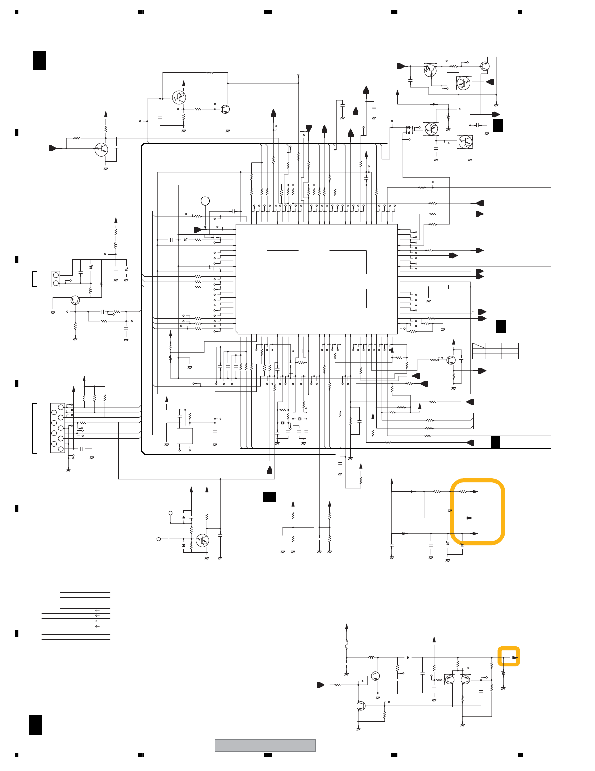
3.3 TUJB ASSY (1/4)
A 1/4
A
TUJB ASSY(1/4)
(VXX3109 : DVR-640H-AV)
(VXX3108 : DVR-540H-S)
V+5V
R101
R166
***
Q101
BLANK
B
toFAN
CN5001
FAN+
1
2
FAN-
B2B-PH-K-S
DBGP2
DBGP1
DBGP0
RESET
GND
RXD1
TXD1
GND
V+5V
GND
CN102
8
6
4
2
VKN2015-
NOTE3
type
ASSY
U301
IC901
R910
R153
R154
R155
R156
9
7
5
3
1
640H/WY
VWM2371
VWV2169
VXF1106-
MSP3417G
C
D
E
F
DTC114TUA-TLB
C5010
0.1/25
Q5006
E
C
B
2SD2114K(VW)-TLB
2.2K
R5002
GND
V+5V
V+5V
R106
R109
100
C103
***
GND
EU
***
***
15K
39K 39K
B
***
C5011
L5005
ATH1109- -T
CH
R107
100K
GND
540H/WY
440H/WY
VWM2370
39K
6.8K
15K15K
1
D5004
2
C5013
470p
R5001
3.3K
100K
GND
R108
A 1/4
20
1234
10K
C
C106
E
V+12R1SW
0
L501
C5014
1SS355-TRB
GND GND
R5003
100K
***
R319
12µ
LCYA120J2520-T
0.1/25
47µ/16
C5015
FANCTL
0
***
C5002
CH
GND
DBGP2
DBGP1
DBGP0
RESET
RXD1
TXD1
C107 R110
******
MRST
TU_CON
HST_TO_M
C120
DBGP2
DBGP1
DBGP0
DAT_TO_M
DAM_TO_T
ASCK
V+5V
HSM_TO_T
TU_CON
GND
1SS355-TRB
B
***
R115
47K
C111
22/25
V+5V
D4002
DTC124EUA-TLB
V+5V
Q103
E
***
C
GND
TEXTV
C119
2.2/50
R158
R159
R160
R146
R147
R148
GND
0.1
R4001
C4001
123
G
IN
NC
NC
4
5
V+5R8E V+5M
D4001
C4003
1SS355-TRB
R4005 R4004
R111
***
24
R144
100
R145
1K
C121
***
100
100
100
100
100
100
10K
BD4846G-TRB
IC4001
OUT
YB1u
0
B
***
Q4001
GND
R185
R4003
C
E
0
C134
C4002
GND
10K
Q104
***
C4004
GND
C
B
E
GND
C123
***
81
***
82
83
84
85
86
87
88
89
90
91
92
93
94
95
96
97
98
99
100
***
***
C109
C110
0.1
0.1
TU_DCCON
1-D3
180
TXD1
RXD1
X525P
R1101
100
R5015
R167
100k
Note1
***
100
100
R125
100K
R143
100K
R142
TXD2
WDT
100
R4002
RXD1
ACDET
R116
SEL_IR
TXD1
LEDDVD
TU_DCCON
81. CVBSIN
82. GND
83. FILTSLC
84. VDDVCO
98. DAT_TO_M
99. DAM_TO_T
100.ASCK
HSM_TO_T
RESET
IR
***
100
C112
100
R117
100
R119
R120
***
VSS1197-
X102
C113
10p
GND
R162
BLANK
XT1
330p
C4009
R121
C114
X525P
XT2
0
10p
R173
78 777980 737476 75 6971 7072 6768 646566 61 606263
RXD2
VDDODA
HST_TO_M
XMSST
XMSPI
XMSRST
GND
VDD3
DBGP2
DBGP1
DBGP0
blank
blank
blank
blank
blank
FLCLK
FLDATA
FLSTB
23417865
100
100
100
***
C108
R114
R112
R113
FLSTB
FLCLK
FLDATA
3/4
A
V+5V V+5V
R155
***
C127
R156
GND GND GND
GND
DVR-640H-AV
1-A3
MUTECTL
0.1
C136
XP_SAVE
SYNCAFT
1-C5,1-D5
GND
EPGEXT
STACHG
100
0
R1115
FLPON
R140
R137
R139
100K
Note1
***
R141
AVLIN
GND
1211910 1413 171615 20 211918 22 23 24 25 28 29 3026 27
R164
1M
X101
12p
C117
39K RD
15K RD
TU_DCCON
MRST
CF1
C115
0
R122
GND
Note13
R161
100K
J_CLOCK
CSYNCIN
XCHECKER
IC101
PMC006A8-K
VDD1
MODEL1
CF2
0.1/25
CSS1653- -T
CH
12p
C129
C126
1-A2
100
100
R104
R174
XP_SAVE
STATCHG
50. blank
49. blank
48. XAVLTH
47. PSMUTE
33. AMUTE2
32. COMPMUTE
31. MUTEV
MODEL2
KEY1
R135
100
R123
R124
KEY1
KEY2
R153
***
R154
2SC4081(QR)-TLB
P_CONT
100
R136
FLON
KEY2
100K
100
Note1
C4005
GND
Note3
Note13
R5009
100
blank
P_CONT
AGC
KEY3
100
R126
AGC
C5016
GND
820
TUON
TUON
BATTDET
4.7K
R127
***
V+5V
V+12R1E
21
IC5001
V+5M
R1112
***0
58 57 5659 53 52 515455
EPGEXT
MUTECTL
P_CONT2
SDET2
FUNC
SDET3
R4009
1K
V+5V
0.1
Note1
Note1
C101
GND
R4026
CEK1278- -T
***
2SC5876(QR)-TLB
C
Q5011
E
GND
1-C4
P_CONT2
C135
GND
FANCTL
C118
GND
VDD2
P_SAVE2
TU_XMODE
SDET1
AVLOUT
100K
R193
R128
Note1
10K
L5003
LRCA331J-T
Q5010
B
GND
B
0.1
0
R149
FANCTL
BLAIR
CONDET
SWSTBY
YVSEL
SELV3
SELV2
SELV1
SDA
Note1
C
E
UMD2N-TLB
AMUTE1
1-C4
***
C3320
V+5R8E
D105
DAP202U-TLB
21
3
B2
UMD2N-TLB
RESET
R1111
50
49
48
blank
blank
RFTHRU
47
46
45
44
43
SQU
42
LET
41
VDD4
40
GND
39
38
37
36
35
34
33
32
31
***
SCL
TUDET
XRST1
R201
V+5V
Note2
10K
***
R163
R152
Note2
R4008
***
Note1
R188
100K
Note1
V+5V
R131
4.7K
R134
4.7K
R1116
***
V+5R8E
D107
1SS355-TRB
1SR154-400-TRB
D106
***
C132
GND GND
1SS355-TRB
D5006
***
R5004
***
C5003
10K
R5005
Q3011
E2
B2
D101
1SS355-TRB
Q105
C2E2B
C140
GND GND
0
R102
0
R157
100
R175
0
R1114
Note1
C116
***
GND
0
R1107
***
R1108
GND
2SC4081(QR)-TLB
R150
100
1-B4
SDET2
SDET3
R105
6.8K
Note1
100
R132
100
R130
100
R171
0
***
C133
V+5R8E
21251u/50
22K
R5010
C5004
C5005
0.1/25
GND
HN1A01FU(YGR)-T
HN1A01FU(YGR)-T
2SD2114K(VW)-TLB
R3318
C2
1K
C
E
C139
100/10
GND
***
UMD2N-TLB
100
B_IR3
V+5V
Q102
C
B
E
R186
470
GND
C131
***
GND
C128
470/6.3
GND
R5011
EBE2
R5008
0
CB2C2
Q5007
UMD2N-TLB
Q3011
Q105
0.1
C102
SCL
SDA
R165
0
C130
1000/6.3
180K
R5014
0
GND
Q3010
B
C
E
Note2
Q5007
B
C153
P_SAVE2
R152
R163
FUNC_IN
TU_CON
SDET1
V+5V
C5018
E
C
MUTECTL
***
GND
AVLIN
XAVLTH
SQU
FUNC_ON
SELV1
AMUTE2
AVLOUT
V+5F
V+5M
R5007
CH
R5006
***
1-A3
GND
A
A
***
0 ***
A
3/4
120K
C341
GND
27K
TU_CON
SAMUTE
2/4
3/4
Tuner OldTuner New
10 k
V+31E
10/50
Page 21
5678
V+5V
R184
V+12R1E
V+5F
12
IC1001
CEK1278-A-T
C4017
C4018
GND
FLSTB
FLCLK
FLDATA
IR
FLPON
KEY1
KEY2
RFTHRU
Note1
***
XRST1
GND
V+5M
TU_CON
C104
X525P
0.1
R172
321
G
IN
NC
4
C105
GND
HST_TO_M
ASCK
DAT_TO_M
HSM_TO_T
DAM_TO_T
XRST1
MRST
L2_RIN
L2_LIN
2VIN
Y2IN
SDET2
1-B3
C2IN
10K
BU4220G-TRB
IC102
OUT
CT
5
YB0.1
A
3/4
B_IR
SPDIF
R_OUT
L_OUT
C_OUT
Y_OUT
YP_OUT
CB_OUT
CR_OUT
A
Y_IN
2/4
C_IN
P_CONT2
R_IN
1-A3
AMUTE1
SW+12R1V V+12R1SW
2SC4081(QR)-TLB
***
C349
1-A3
L_IN
C350
YF
R317
R202
Q310
100
0.1
***
***
GND
1
2
3
4
5
6
7
8
9
10
11
12
13
14
15
16
17
18
19
20
21
22
23
9604S-23C
CN101
GND
SW+12R1V
Note1
R4020
***
C5001
***
8
9
1013
1114
12
15
19
23
R170
20
GNDA0GND
***
E
C
B
100/16
C351
GND
GND
FLSTB
FLCLK
FLDATA
GND
IR
V+5F
V+12R1E
FLPON
KEY1
KEY2
GND
2R
GND
2L
GND
2V
GND
2Y
GND
SDET2
GND
2C
Note1
1M
R169
R168
1M
1-A2,1-C5
XP_SAVE
from SYPS
CN202
J
P_ON
EV+12R1
GND
EV5R8
GND
CN303
B5B-PH-K-S
CN7301
C
CN4002
VKN1439- -TBB
RXDGL
1
TXDGL
2
B_IR
3
SPDIF
4
GND
5
HST_TO_M
6
ASCK
7
DAT_TO_M
8
HSM_TO_T
9
DAM_TO_T
10
XRST1
11
SW+12R1V
12
R_OUT
13
GNDA
14
L_OUT
15
MRST
16
C_OUT
17
GND
18
Y_OUT
19
GND
20
YP_OUT
21
GND
22
CB_OUT
23
GND
24
CR_OUT
25
GND
26
X525P
27
Y_IN
28
GND
29
C_IN
30
P_CONT2
31
L_IN
32
GND
33
R_IN
34
AMUTE1
35
V+12R1E
DTC124EUA-TLB
5
4
3
2
1
GND
TU_CON
Q811
E
R811
C
B
E
Q810
GND
C309
***
C302
*** GND
2SA1036K(QR)-TLB
C
B
1K
P_CONT
V+5R8E
TUON
TUON
P_CONT
CN2301
3/4
F
XP_SAVE
1-A2,1-D5
1K
R810
1SS355-TRB
D811
0.1
C810
C812
D810
1
2
UDZS9R1(B)-TRB
TU_CON
UDZS15(B)-TRB
D301
***
C346
GND
V+31E
L302
C332C348
GND
GND
2SC2411K(QR)-TLB
Q812
C
E
B
100/10
C811
0.1
V+12R1E
0
R151
C
B
***
R337
***
C334
C335
***
GND
V+5R8E
2SA1036K(QR)-TLB
100/16
C319
***
C320
CTF1399- -T
B2
*** ***
V+5R8E
R6316
470
Q6008
RN4903-TRB
***
C6425
C6647
***
GND
GND GND GND GNDGND
V+5R8E
***
C314
R310
GND
***
C347
Q307
DTC124EUA-TLB
GND
V+9V
100/10
C813
V+12R1
Q313
B
B2
***
B
E
Q314
E
D5003
GND
***
R307
R311
***
C336
Q301
E
C
B
R309
560
C
E
DTC124EUA-TLB
GND
***
C
Q306
UMF23N-TLB
B
33K
C2
Q306
UMF23N-TLB
E2
2SC2411K(QR)-TLB
Q6008
RN4903-TRB
E
B
C2
C6649
E2
2SA1036K(QR)-TLB
Q302
E
C
B
(2125)
470
C321
C
E
C
R308
Q6009
100/10
***
220
E
C
B
***
C6427
R312
C322
V+5TU
V+31V
***
C343
GND
YB
C6428
0.1/16
Q303
2SC2411K(QR)-TLB
C
E
B
100
***
C323
C324
100/16
GND
C333
A
Note1
EU
R184
***
R4007
***
C128
470u
C130
1000u
C4005
***
R4026
10 k
C101
0.1
R127
4.7 k
R105
6.8 k
R188
100 k
***
R4008
0
R1114
***
R141
R142
***
R168
1M
R169
1M
R193
100 k
R128
***
***
B
C
V+5R1
D
V+5VI
0
***
C325
(2125)
***
R313
V+5VO
E
56
DVR-640H-AV
RN4903
C
E2B2
CB2 E2
VC
C2BEEBC2
A 1/4
F
21
7
8
Page 22
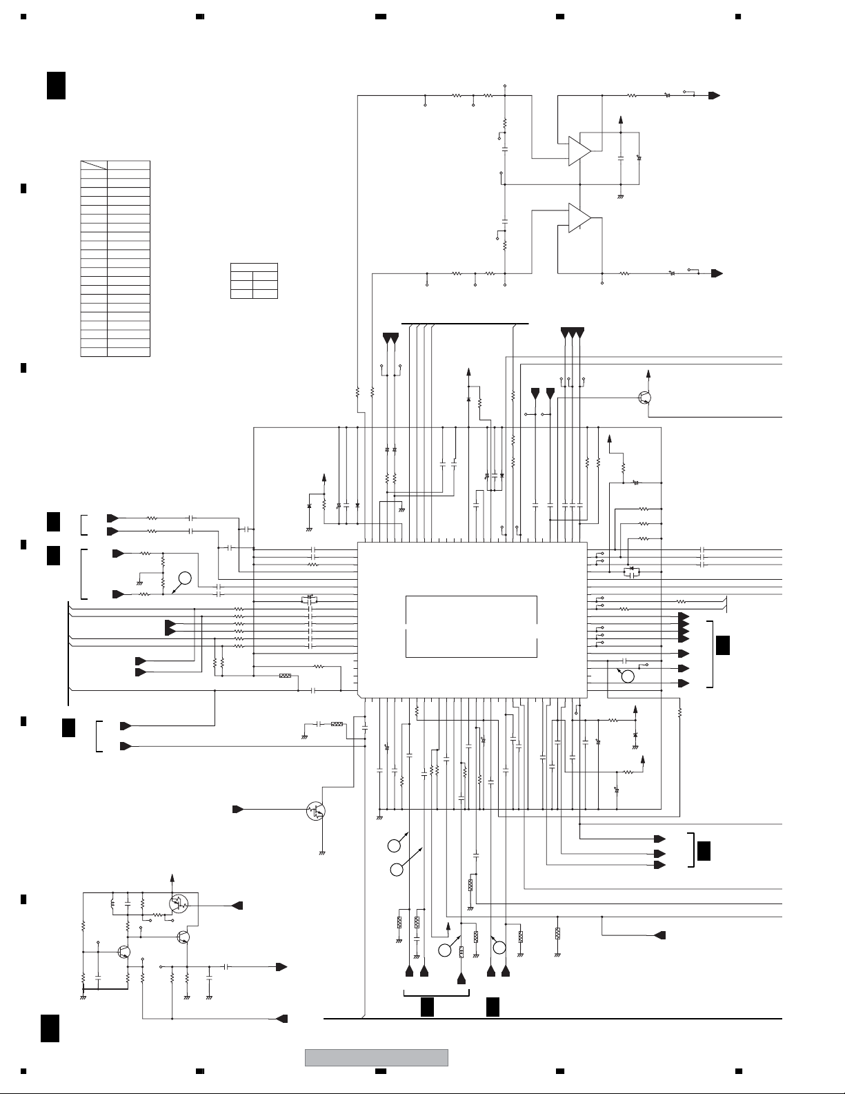
1234
3.4 TUJB ASSY (2/4)
A
B
C
D
E
F
A 2/4
22
A 2/4
Note7
R49
R50
C81
C82
R3510
R3511
C74
C75
C16
C18
R2016
R2017
R423
R2072
C13
R187
R183
C68
C69
R405
3/4
4/4
AV2_RIN
AV2_LIN
WY only
AV1_RIN
RGB_YIN
A
AV1_LIN
3/4
R176
R180
GND
L3_RIN
3.3k
1.5k
A
A
AV_BUS
TUJB ASSY(2/4)
(VXX3109 : DVR-640H-AV)
(VXX3108 : DVR-540H-S)
<AUDIO SELECTOR BLOCK>
WY
470
470
1/10YB
1/10YB
***
***
0.1/25YF
0.1/25YF
***
L3_LIN
TU_RIN
TU_LIN
C142
L1_RIN
Y1IN
C1IN
L101
LAU470J-TA
Q107
1u
0.1/25YF
180F
180F
***
1M
1/10YB
***
680
100p
100p
270F
Note7
Note7
L1_LIN
DTA143EUA-TLB
47u
C141
R177
C
B
2SC4081(QR)-TLB
E
R181
R43
R45
220
GND
10p
750F
R58
R59
L2_RIN
L2_LIN
R178
R182
C50
470
C51
470
470
R42
***
R44
21
***
470
V+5VI
Q106
E
470
R179
C
0
Q108
C
B
***
680
Note7
R187
R183
GND GND
1u/10 YB
1u/10 YB
C72
C73
***
R3510
Note7
P_SAVE2
B
2SC4081(QR)-TLB
E
Note7
C143
680
***
Note7
C75
0.1/25
1u/10 YB
1u/10 YB
R56
R46
R47
R48
R49
R50
***
R3511
C144
1u/10
Note9
R22
R24
R26 1M
Note7
EU
Note7
C74
0.1/25
470
470
470
470
470
470
EPGEXT
1M
***
UDZS11(B)-TRB
Note7
Note7
***(2125)
D1
GND
C70
C71
R36
C76
C5
C77
C78
C79
C80
C81
Note7
Note7
C82
R2002
C19
GND
B
Q2
DTC124EUA-TLB
TEXTV
1-A6
TEXTVIN
V+9V
0
R41
0.1/25
0.1/25
10K
4.7/50
1/10 YF
1u/10
YB
1u/10
YB
1u/10
YB
1u/10
YB
1u/10
YB
1u/10
YB
1M
R2019
1/10 YB
IC100
HA118326APFR-K
YB***
***(2125)
C2003
R2018
C
E
GND
AV_BUS
WY only
AV2_LOUT
AV1_ROUT
A AV2/OUT(L)
A AV1/OUT(R)
SEP C2 IN
SYNC DET
100k
R15
YB
***
0.1/16
C8
R701
10kD
R703
10kD
AV_BUS
AV2_ROUT
V+5VI
0.1/25
0.1/25
Note7
C68
C69
Note7
A AV2/OUT(R)
A AV1/OUT2(L)
A AV1/OUT2(R)
A HorHDD/OUT(L)
A HorHDD/OUT(R)
VIDEO L3 IN
59/61PIN
S1/S2 B OUT
GND
VIDEO L2 IN
1312 1514 1917 201816 22 23 2421 2726 28253129 30
YB0.1/16
YB
1M
1/10
C12
R2073
0
C10
R16
R18
1/10 YB
C11
L_SWIN
R_SWIN
R_OUT
L_OUT
AV1_LOUT
0
0
R64
R65
NP
NP
C67
4.7/50
C66
4.7/50
560
560
R51
100/10
C44
100
R52
1/10
C43
***
D8
GND
80 79 7778 7476 75 7073 7172 66676869 616465 6263 58 575960
81
82
83
84
85
86
A TUNER IN(R)
87
A TUNER IN(L)
88
VREF(9V/2)
89
A L3 IN(R)
90
A L3 IN(L)
91
A L2 IN(R)
92
A L2 IN(L)
93
A L5 IN(R)
94
A L5 IN(L)
95
GND
96
97
98
99
To DVD(L)
To DVD(R)
A DVD M C
F A DVD(L)
DL3 DRIVE
SEP Y1 IN
V C&S C3 IN
SYNC DET
2165743119108
YB
C2
1/50
1/10
C4
0.1
C3
GND
VCC
F A DVD(R)
A AV1/OUT(L)
81:A HIFI IN(R)
82:A HIFI IN(L)
83:V DVD M C
84:A L4 IN(R)
85:A L4 IN(L)
96:A AV1 R OUT(R)
97:A AV1 R OUT(L)
98:RF-C A OUT
99:A AGC D
100:VTR VorY&S Y3 IN
SEP Y2 IN
SYNC DET OUT
SEP C1 IN
1/10
C7
0.1/25
1M
C6
R2024
17
18
RGB_CIN
75F(2125)
GND
R2003
YB
0.01
GND
Y2IN
75F(2125)
C2005
A
R2015
C2IN
V+5VI
16
3/4
GND
L2005
2VIN
R3001
***
D3
YB
C54
0.1/16
MAIN C D
VIDEO AGC
VIDEO L1 IN
FBC
1M
R2072
Note7
YB
1/10
C13
***
R2074
75F(2125)
GND
CTF1388- -T
0
C702 C701
R3002
0
0
R55
0.1/25
100/10
C39
C38
VCC
MAIN C IN
SLICER OUT
SCART RorC IN:49
SCART G IN:48
PY(Y)/G OUT:46
S1/S2 B OUT:33
RS IN D OUT
BS IN
BG
10/50
C14
YB
1/10
C26
Note7
R2006
1
TU_VIN
A
4/4
R707
8.2kD
10/10
10/10
R708
8.2kD
BLANK
R103
0
00
R138 R133
***
D7
DVD C OUT
PAL SCART IN
DVD VorY OUT
SCART B IN:50
VCC:47
V2 OUT:32
GND:31
TUNER IN
AV2 OUT
FBCD
0.1/25
YB
C18
0.1/16
Note7
YB
C17
***
C16
Note7
R2013
***(2125)
GND
3VIN
BA4560RF-TBB
C_OUT
YB
YBYBYB
0.1/16
1/10
C49
C48
56 55 5354 52 51
F DVD Y
F DVD C
PAL SCART D2
PAL SCART D1
Pr(Cr)/ RorC OUT
VTR OUT
GND
FBCD
V1 OUT
YB
0.1/25
0.1/16
C20
C21
***(2125)
GND
2
3
+
+
5
6
CB_OUT
Y_OUT
1/10
1/10
C46
C47
RGB M OUT
F DVD Pb(B)
Pb(Cb)/B OUT
SYNC
PY(Y) OUT
Pr(Cr)/ OUT
Pb(Cb)/ OUT
Y2 OUT
FBCD
C2 OUT
C1 OUT
VCC
YF
***
0.1/25
C2007
C22
R2014
8
-
4
4
BA4560RF-TBB
-
8
YP_OUT
CR_OUT
***
R2042
YB
1/10
C45
50
49
48
F DVD Pr(R)
F DVD PY(G)
47
46
45
44
43
SCL
42
SDA
41
40
39
38
37
GND
36
35
34
33
32
VCC
Y1 OUT
***
C2006
1
IC701
IC701
7
C23
***
R39
V+12R1SW
R3163
V+5VO
0
R6
100/10
R57
R3164
GND
Note9
Note9
C24
R38
C30
V+5VO
C730
0
Note9
V+5VO
0
C9
0.1/25
100/10
3
C25
100
D2
GND
R31
R26
R24
R22
0
C3111
100/16
0
C
B
E
1M
***
1M
D6
***
0.1/25
0.1/16
YB
UDZS6R8(B)-TRB
C711
10/50
C712
10/50
V+5VI
Q4
2SD2114K(VW)-TLB
R19
R2070
Y2OUT
C2OUT
2VOUT
1VIN
100
3.3M F
C42
C41
C40
SYNCAFT
YOUT
CROUT
CBOUT
Y1OUT
C1OUT
1VOUT
A
1/10
SCL
SDA
YB
YB1/10
YB1/10
A
3/4
3/4
L_IN
R_IN
TU_CON
DVR-640H-AV
1234
Page 23
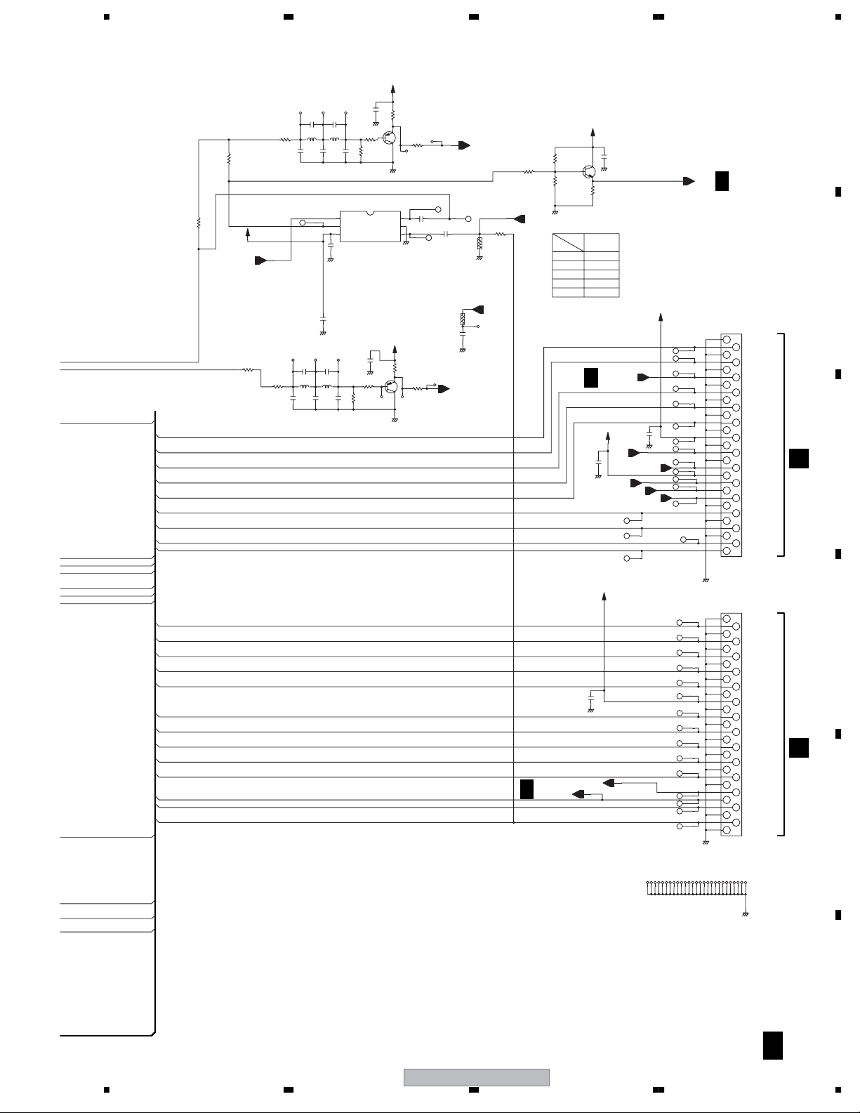
5678
RGBOUT
R/COUT
AV1_V/YOUT
R/CIN
BIN
GIN
GOUT
BOUT
Y IN
C IN
AV1_ROUT
AV1_LOUT
AV1_RIN
AV1_LIN
BOUT
GOUT
R/COUT
RGBOUT
AV1_V/YOUT
AV1_V/YIN
AV2_ROUT
AV2_LOUT
AV2_RIN
AV2_LIN
RGB_YIN
R/CIN
GIN
RGB_CIN
BIN
BLANK
AV2_V/YOUT
AV2_V/YIN
***
R195
180F
R2017
Note7
Note SELV1 :
WY TEXTV for TEXT TV
IBD for LINE INPUT3
Note7
SELV1
R2016
180F
V+5VI
R405
V+5VI
A
C403
C404
7p
3p
L401
L402
18µ
15µ
R402
270F
430
82p
33p
C405
C406
1
25
34
C33
***
GND
C2001
***
GND
C410C409
7p3p
L403
L404
18µ15µ
82p
33p
C411
C412
68p
0.1
C407
GND
R403
B
10
***
68p
C408
R404
GND
IC2002
MM1503XN-TRB
SW
OUT
Vcc IN 2
C413
***
0.1
C443
GND
Q410
R438
B
10
R406
2SA1576A(QR)-TLB
GND
R401
470
Q401
E
2SA1576A(QR)-TLB
C
Note8
6
IN 1
GND
V+5VI
R424
470
E
C
GND
R89
C2109
1/10
R90
V+5VI
1/10
Note8
C36
YB
R2062
GND
C_IN
Y_IN
R425
R196
0
***
R2001
GND
C3IN
***
***
C2002
Note8
AV2 Vin
A
Y3IN
0
1/4
GND
R442
R443
Note8
BLANK
***
***
R195
R196
IC2002
C2109
C36
Q409
B
FUNC_IN
R426
A
GND
1k
GND
***
***
C442
2SC4081(QR)-TLB
C
GND
E
WY
***
0
1503
1µ/10
1µ/10
1/4
V+5V
***
C4019
AVLIN
AVLOUT
V+5VI
C4021
SAMUTE
SQU
XAVLTH
***
GND
FUNC_ON
V+12R1
C4020
TEXTVIN
1-D2
GND
GND
A
1/4
1
2
3
4
5
6
7
8
9
10
11
12
13
14
15
16
17
18
19
20
21
22
23
24
25
26
27
28
29
VKN1433- -TBB
CN604
1
2
3
4
5
6
7
8
9
10
11
12
13
14
15
16
17
18
19
20
21
22
23
24
25
26
27
28
29
CN605
VKN1433- -TBB
GND
AV1_R_OUT
GND
AV1_L_OUT
GND
SAMUTE
GND
AV1_R_IN
GND
AV1_L_IN
GND
AV1_B_OUT
GND
V+12R1
GND
SQU
GND
FUNC_OUT
V+5V
AVL_IN
AVL_OUT
XAVLTH
GND
AV1_G_OUT
GND
AV1_R/C_OUT
GND
BLANK_OUT
AV1_V/Y_OUT
GND
AV1_V/Y_IN
GND
AV2_R_OUT
GND
AV2_L_OUT
GND
AV2_R_IN
GND
AV2_L_IN
GND
V+5VI
GND
Y(RGB)
GND
AV2_R/C_IN
GND
AV2_G_IN
GND
C(RGB)
GND
AV2_B_IN
GND
FUNC_IN
BLANK_IN
AV2_V/Y_OUT
GND
AV2_V/Y_IN
GND
CN1
B
CN2
B
B
C
D
E
0
Note8
YB
0
AV2_V/YOUT
AV1_V/YIN
AV2_V/YIN
56
DVR-640H-AV
GND
F
A 2/4
23
7
8
Page 24
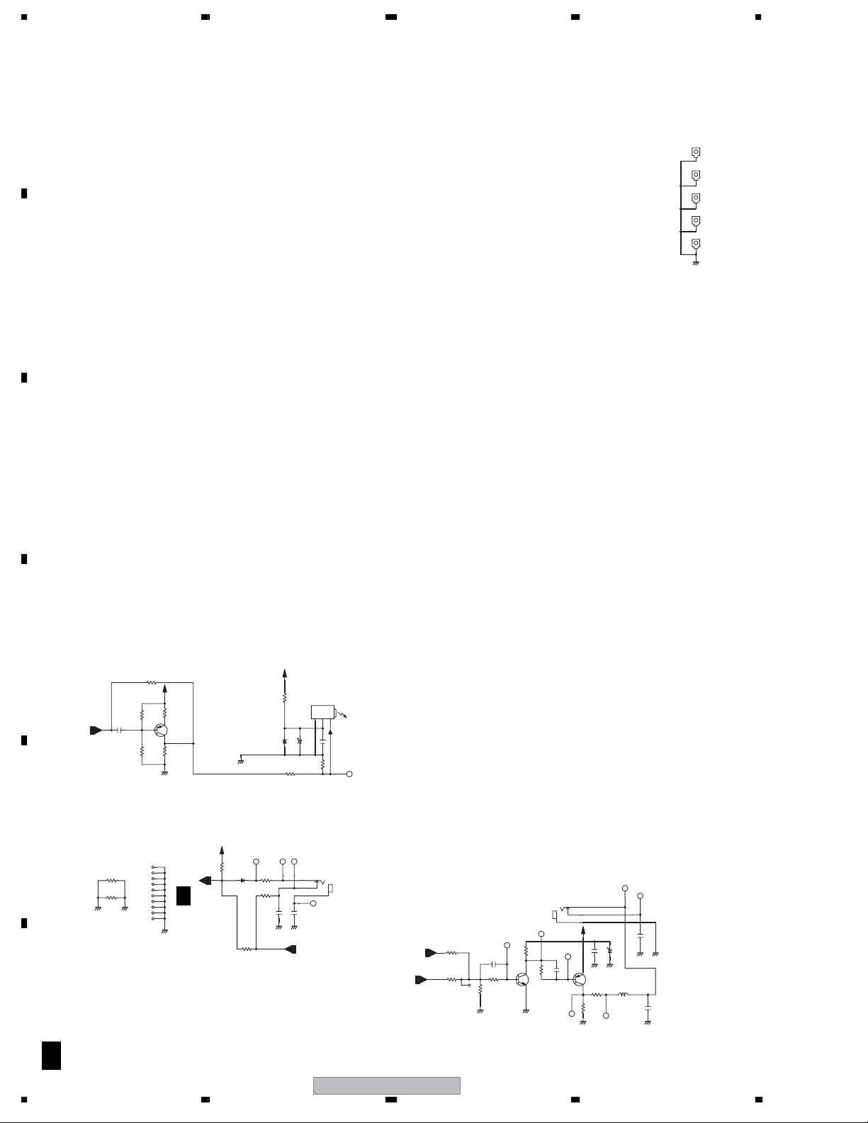
1234
3.5 TUJB ASSY(3/4)
A
B
KN401
***(VNF1084- -T)
KN402
***(VNF1084- -T)
KN403
***(VNF1084- -T)
KN404
***(VNF1084- -T)
KN405
VNF1084- -T
GND
C
D
GND
R4030
***
220
R4029
220
D3709
V+5R1
R3708
***
R3704
C4015
***
1
2
C3706
***
2
3
1
CH
0.1
C4016
***
GNDGND
IR
<OUTPUTS>
JA4003
***
321
***
***
C3707
***
R3705
JA4002
RKN1004-
OPTICAL
B_IR
B_IR3
R194
R192
***
0
C4011
CH100p
R4013
B
4.7K
R4014
4.7K
GND GND
IR BLASTER
1K
R4011
C
R4012
Q4003
E
2SC4081(QR)-TLB
RKN1004-
C4012
4.7K
CH
100p
JA4001
B
2
3
1
V+5V
C4014
***
C4010
GND
E
Q4002
2SA1576A(QR)-TLB
C
R4015 L4001
150 ***
1K
R4016
GND
GND
***
(R99 0)
C4007
***
GND GND
C4013
GND
CH***
***
R3701
V+5R1
***
R3702
***
R3703
***
E
R3706
Q3701
***
B
C
***
***
R3707
GND
V+5V
R4027
220K
1/4
D4005 R4028
1SS355-TRB
SEL_IR
A
GND
SPDIF
1-A4
C3701
E
R118
0
R129
0
GNDGNDA
F
A 3/4
24
DVR-640H-AV
1234
Page 25

5678
A
1/4
AMUTE2
AMUTE1
A 3/4
SPDIF
1-C1
A
1/4
V+5V
D3202
1SS355-TRB
C3128
220/6.3
GND
D3201
1SS355-TRB
***
C3126
***
C3129
TUJB ASSY(3/4)
(VXX3109 : DVR-640H-AV)
(VXX3108 : DVR-540H-S)
V+5R1
***
Q2001
B
R2005
***
C2008
GND
B
C
Q3211
DTC124EUA-TLB
E
R2004
***
R2010
R2026
0
E
Q3210
DTA124EUA-TLB
C
***
C
B
E
R2007
***
***
***
R2012
***
C3131
1-C4
AMUTE
C2004
A
B
C2032
R2008
1/50
0
***
A
GND
2/4
R2009
100k
D2004,D2005:UMZ6R8N-TLB
YOUT
CBOUT
CROUT
5
7
C2035
1000/6.3
R2011
6
C2034
C2033
470/6.3
R2023
470/6.3
75F(2125)
75F(2125)
R2025
75F(2125)
AUDIO OUTPUT
VKB1159-
3
D2004
***
21
3
D2005
***
21
3
D2010
***
21
GND
DIGITAL
JA2004
1
2
3
2
1
4
JA2010
VKB1165-
Y
Cb
Cr
OUTPUT
COMPONENT
C
GND
A
2/4
Y1OUT
C1OUT
1VOUT
L_OUT
AMUTE
R_OUT
D2011
2
C2036
1000/6.3
C2011
0.01/50
C2037
C
B
E
E
B
C
YB
1000/6.3
Q3001
2SD2114K(VW)-TLB
Q3002
2SD2114K(VW)-TLB
4
22
L_OUT
1-B4
AMUTE
C2038
47/16
C2039
47/16
R2032
R2053
R2030
470
R2031
22K
1K
R2052
1K
22K
R2054
470
R2027
R2050
R2029
75F(2125)
UMZ6R8N-TLB
75F(2125)
75F(2125)
R2051
R2055
231
231
3
21
100
100
D2012
D2013
C2028
C2029
***
UMZ6R8N-TLB
GND
CH
470
CH 470
JA2003
1
VKB1193- EU
3
Y
5
S1
C
4
2
12
V1
14
L1
15
17
18
20
OUTPUT1
R1
D
GNDA
E
56
DVR-640H-AV
F
A 3/4
25
7
8
Page 26
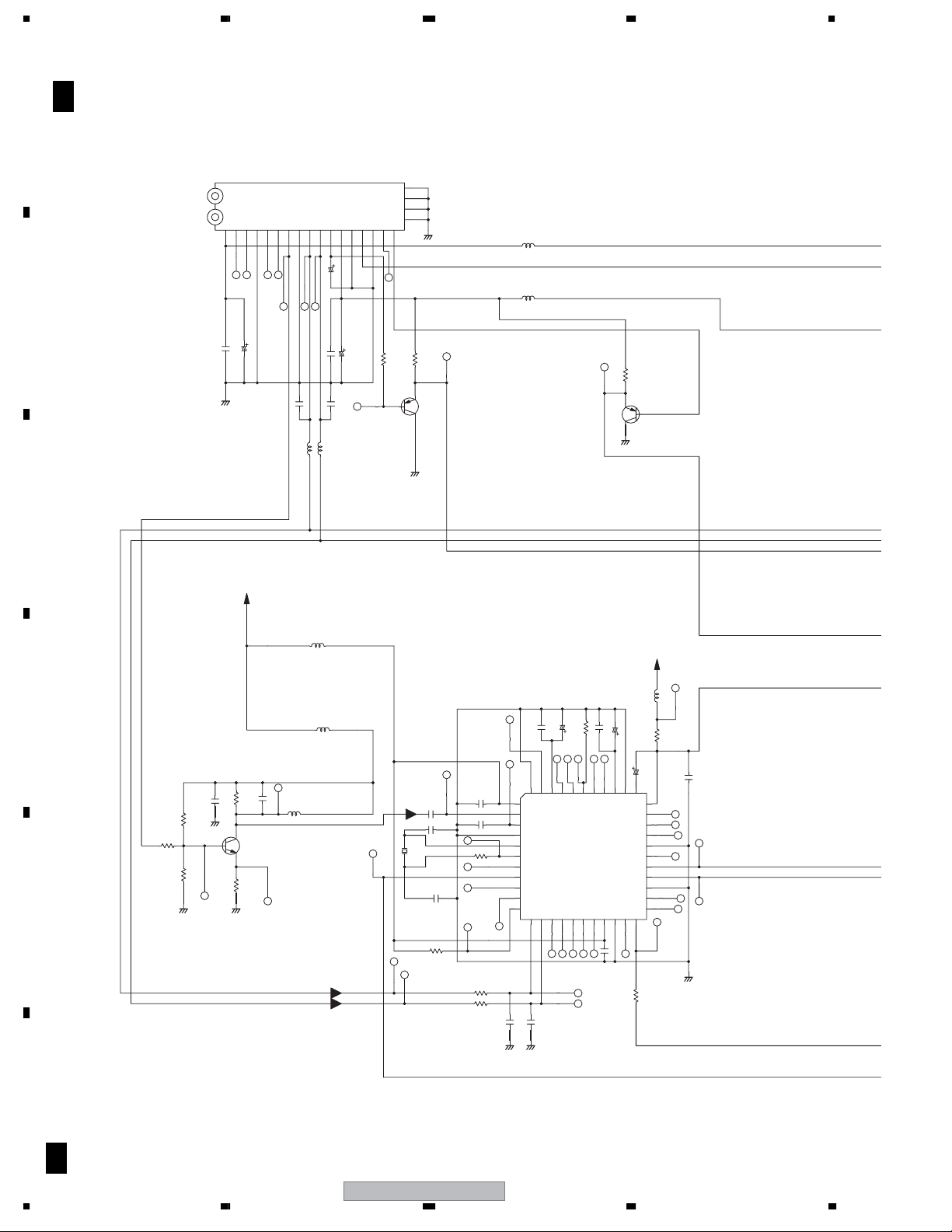
1234
3.6 TUJB ASSY(4/4)
A
B
C
A 4/4
TUJB ASSY(4/4)
(VXX3109 : DVR-640H-AV)
(VXX3108 : DVR-540H-S)
EU
VXF1106-
U301
SIFOUT
AUDIOOUT
NC
NC
BB(5V)
NC
1324 859761210 11 13 14 15 16 17
YB
1000/6.3
2200p
C313
C301
GND
GND
SCL
33p CH
C306
L305
CTF1306-T
VTL1081--T
MB(5V)NCAFT
AGCOUT
SDA
C310
22/25
YB
1000/6.3
2200p
C5506
C5507
CH33p
C307
L306
CTF1306-T
NC
GND
TU(31V)
R305
VIDEO
1K
B
21
20
19
18
GND
R306
E
C
GND
10K
Q5009
2SA1576A(QR)-TLB
<U/V TUNER BLOCK>
L301
CTF1399- -T
L5004
CTF1399- -T
E
C
GND
R301
1K
B
Q5008
2SA1576A(QR)-TLB
V+5R1
L901
CTF1399
MULTI SOUND DECODER
IC901
MSP3417G-TBB
56p
3p
C915
3p
R923
10k
R925
R926
Note R910 EU,YPW (*** ) Note R910 EU,YPW (*** )
C905
2
0.1/25
C908
3
4
56p
5
R905
6
7
0
8
9
R907
10
11
100
100
CH
C930
***
GND GND
D
R927
R929
4.7k
2.2k
C901
GND
SIF AMP
YB
330
R931
0.01
C
B
E
Q906
100
R933
GND
2SC4081(QR)-TLB
SIF
R928
22
E
GND
C909
LCYA101J2520-T
100p
L902
10µ
L903
C906
C907
X901
18.43MHz
VSS1189- -T
(EU,YPW)
***
0.1/25
C917
AVSS
4414143 4042 35373839 363334
AVSUP
AIN1+
AIN1TESTEN
XIN
XOUT
TP
DCO1
DCO0
ADSEL
STBYQ
12 15 1613 14 1918 2017 212322
C931
C937
MONOIN
VREFTOP
41:SCIR
12:SCL
13:SDA
TPTPTPTPDVSUP
CH
***
R910
C918
10/50 AL
39:NC
40:NC/ASG
22:RESETQ
38:NC
0.1/25
C938
37:NC
C929
3.3/50 AL
AHVSS
AGNDC
AHVSUP
SCOL
SCOR
VREF1
DACML
DACMR
VREF2
DVSSTPTP
1µ
L904
C939
CAPLM
NC
TP
TP
TP
0
R924
V+5R1
R909
10/50
32
31
30
29
28
27
26
25
24
CTF1399
0(2125)
GND
C919
0.1/25
F
A 4/4
26
DVR-640H-AV
1234
Page 27
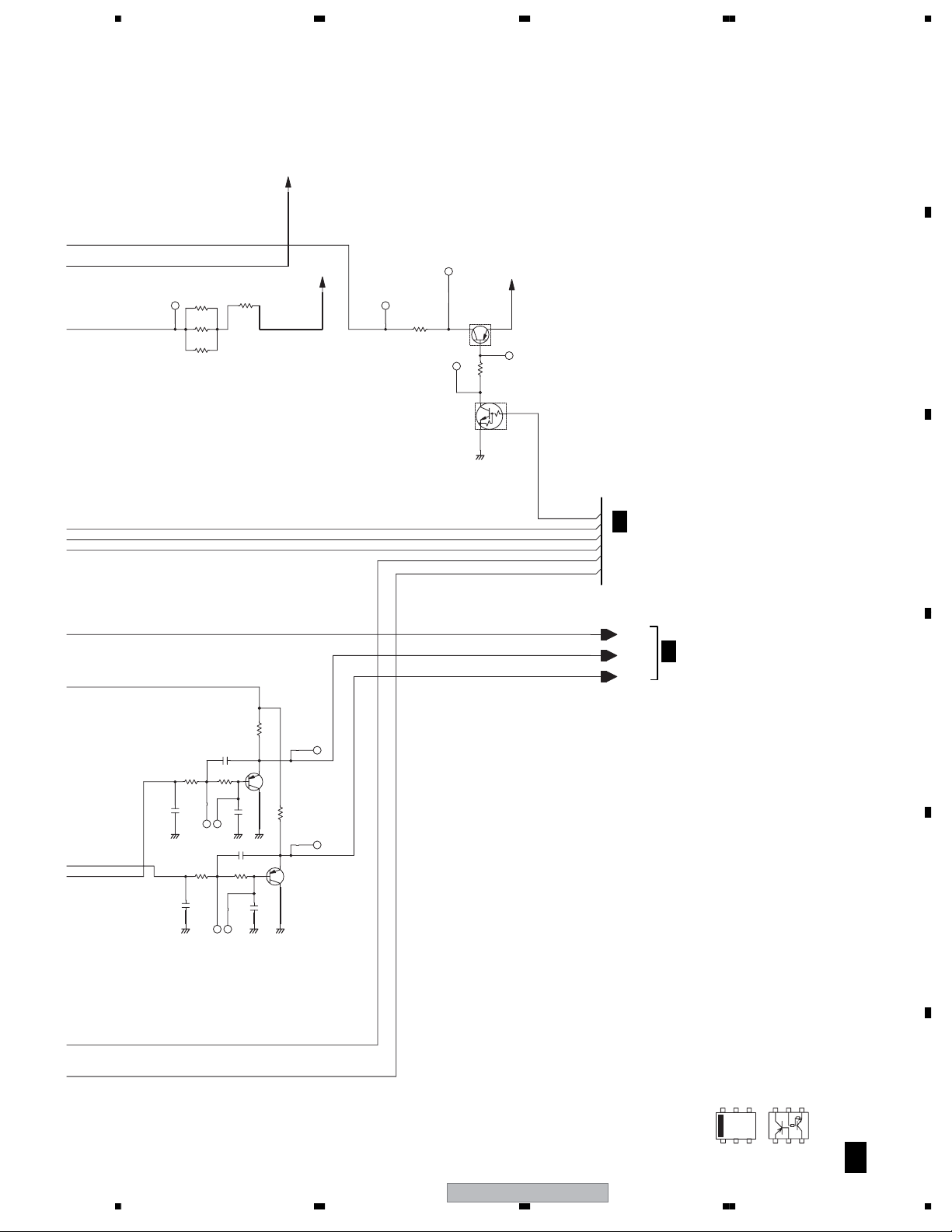
5678
A
V+31V
R6317
R302
10(2125)
R304
10(2125)
R5012
12(2125)
R918 R919
3.3k 3.3k
YB
C924
3900p
GND
R921 R922
3.3k
YB
C927
GND GND GND
3900p
C923
YB
0.01
C925
GND GND
C926
0.01
3.3k
0
B
CH
560p
C928
1k
R917
E
Q903
C
2SA1576A(QR)-TLB
YB
B
CH
560p
V+5TU
1k
R920
E
Q904
C
2SA1576A(QR)-TLB
R303
12(2125)
Q6001
UMF21N-TLB
Q6001
UMF21N-TLB
C
C2
E2
GND
B
R6002
V+5R8E
E
1K
B
B2
RFTHRU
SCL
SDA
AGC
XRST1
STACHG
TU_CON
A
1/4
TU_VIN
TU_RIN
TU_LIN
A
2/4
C
D
E
56
DVR-640H-AV
UMF21N
CE2B2
EC2BEBC2
CB2
E2
F
A 4/4
27
7
8
Page 28
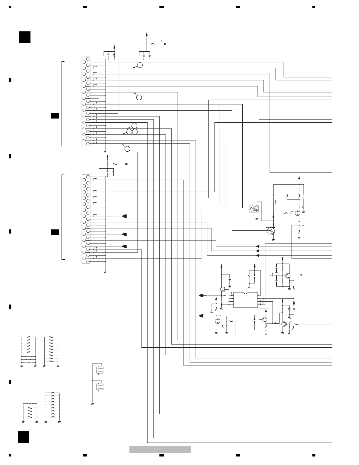
1234
3.7 SCRB ASSY
A
B
C
D
E
F
SCRB ASSY (VWV2206)
B
VKN1260-
GND
AV1_R_OUT
GND
AV1_L_OUT
GND
SAMUTE
GND
AV1_R_IN
GND
AV1_L_IN
GND
AV1_B_OUT
GND
V+12R1
0
R203
0
R204
0
R205
0
R206
0
R207
0
R208
0
R201
R202
0
R218
0
GND GNDGND
R232
0
R231
0
R219
0
R220
0
R221 R230
0
GNDGND GND GND
R209
R210
R211
R212
R213
R214
R215
R216
R217
R222
R223
R224
R225
R226
R227
R228
R229
CN604
0
0
0
0
0
0
0
0
0
GND
0
0
0
0
0
0
0
0
0
FUNC_OUT
A 2/4A 2/4
AVL_OUT
AV1_G_OUT
AV1_R/C_OUT
BLANK_OUT
AV1_V/Y_OUT
AV1_V/Y_IN
AV2_R_OUT
AV2_L_OUT
AV2_R_IN
AV2_L_IN
CN605
AV2_R/C_IN
AV2_G_IN
AV2_B_IN
FUNC_IN
BLANK_IN
AV2_V/Y_OUT
AV2_V/Y_IN
V+5V
AVL_IN
XAVLTH
V+5VI
Y(RGB)
C(RGB)
GND
SQU
GND
GND
GND
GND
VKN1260-
GND
GND
GND
GND
GND
GND
GND
GND
GND
GND
GND
GND
GND
GND
CN1
2
4
6
8
10
12
14
16
18
20
22
24
26
28
CN2
2
4
6
8
10
12
14
16
18
20
22
24
26
28
V+5V
V+12R1
C2088
***
C2087
2
413
2
43
GND
GND
KN402
1
***
V+5VI
R2050
0
C2084
C2083
***
***(VNE1948-)
KN401
***(VNE1948-)
100/10
6
V+5VIR
7
RGB_YIN
1-C5
RGB_CIN
1-C5
FUNC
1-B6
9
1
3
5
7
9
11
13
15
17
19
21
23
25
27
29
1
3
5
7
9
11
13
15
17
19
21
23
25
27
29
GND
R2049
0
V+5VR
C2085
***
C2086
***
11
10
8
SAMUTE
V+12R1
2SC4081(QR)-TLB
RGB_YIN
1-C2
V+5VI
C2118
RGB_CIN
1-C2
GND
2SA1576A(QR)-TLB
Q2010
BOUT
RGB_GOUT
BLANK
V+5VI
Q2009
R801
1.5k
GND
VDD
CH0
CH1
V+5VI
Q2008
C2
E2
C2115
8
7
6
***
B
Q804
UMH1N-T
***
C
B
E
R2040
2SA1576A(QR)-TLB
GND
UDZS5R1(B)-TRB
D819
1
2
D816
1
2
C
E
GND
V+5VI
C2110
GND
C2109
0.1/25
V+5VI
V+5VI
C2114
47K
220/16
Q2011
Q804
UMH1N-T
B2
SQU
FUNC_ON
BIN
RGB_GIN
R/CIN
C2117
***
C2116
C
B
GND
E
1
R2041
1K
2
3
45
1K
R2042
***
GND
E
R2043
B
C
R3001
1.6K
1.5K
R2044
***
GND
GND
R/COUT
RGBOUT
AV1_V/YOUT
AVL_IN
***
GND
COMMON
INH
IC2006
VEE
TC4W53FU-TRB
VSS A
2SC4081(QR)-TLB
C2111
R810
560
(2125)
2SA1576A(QR)-TLB
R802
10
UDZS5R1(B)-TRB
R2017
22K
***
Q2007
B
R2024
33K
R2026
GND
1K
R2045
C2119
GND
E
B
C
1.5K
GND
GND
R811
1.2k
(1608)
E
GND
B
C
Q806
2
D820
1
1SS355-TRB
56k
R812
GND
2SC4081(QR)-TLB
C2113
C
220/16
E
47K
R2051
1.8K
L2001C2051
LAU620J-T33p
***
R2046
1.6K
R2047
R3000
***
***
C805
28
B
AVL_OUT
XAVLTH
DVR-640H-AV
1234
Page 29
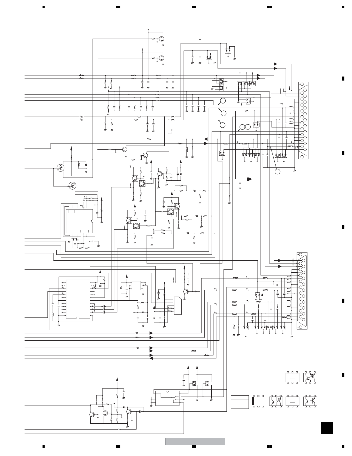
Q803
DTA124EUA-TLB
22p
LAU680J-TA
AV1_ROUT
AV1_LOUT
AV1_RIN
AV1_LIN
AV2_RIN
AV2_LIN
AV2_ROUT
AV2_LOUT
AV2_V/YIN
AV2_V/YOUT
1SS355-TRB
E
B
C
Q805
DTA124EUA-TLB
13
14
15
16
17
18
19
0.1/25
20
C2012
21
22
C2011
23
68u
24
L2000
GND
5678
C
R808
Q820
B
2SD2114K(VW)-TLB
3.9k
E
GND
C
R809
Q821
B
C62
C63
C60
C61
V+12R1
D801
C833
E
B
C
910121314
11
A2
B2
R2
Q2
IC2005
TC74HC123AF-TBB
VSS
R/C2C2Q2Q1R1
87456
C2107
R2036
GND
180K
470K
0.01u ML
R2035 R2034
IC2000
BH7236AF-TBB
NCNCSYNCOUT
COUTNCSYNCIN
YOUT
YTRAP
NC
VCC2
VOUT
BOUT
GOUT
ROUT
GND GND
STEP_UP only
4.7/50
4.7/50
4.7/50
4.7/50
***
C834
GND
C2108
C1
Q1
BFPOUT
NT/PAL
SCIN
0.1u ML
3
10K
VCC
NC
BIN
GIN
RIN
Q810
100/16
R2027
47K
120K
R2016
16
15
VDD
R/C1
GND HN1C01FU(YGR)-T
B1
A1
2
1
C2126
0.1/25
GND
0.1/25
R100
C2123
12
11
GND
10K
10
9
8
7
6
5
4
YB
3
YB
2
1
4.7k
R844
C
B
E
2SC4081(QR)-TLB
100K
R3601
GND
GND
R60
100k
GND
100K
R3603
GND
GND
R827
3.9k
V+5VI
C2103
***
0.1/25
C2102
HN1C01FU(YGR)-T
V+5VI
C2122
***
0.1uYB
C2089
0.1u
C2090
0.1u
C2091
47k
R846
R845
2.2M
C
B
E
Q811
C871
2SC4081(QR)-TLB
100k
R3602
470
100k
C840
CH
R62
100K
R3604
B
HN1C01FU(YGR)-T
HN1C01FU(YGR)-T
Q2003
V+5VI
C2058
***
V+5V
C872
27k
R847
GND
D829
1SS355-TRB
220k
CH
R849 R848
100k
220p
R851
100k
R28
470 100
R30
470
C841
470
CH
R25
C
Q823
2SD2114K(VW)-TLB
E
R828
GND
3.9k
Q2001
C
Q2001
E
R2009
1K
GND
V+5VI
R2018
1KF
C
B
C2
E
Q2003
E2
R2023
R2019
1K
560
GND GND
TC7SU04FU-TLB
IC2004
51
VCC NC
43
OUT GND
***
C2059
GND
R2003
C35
C37
C36
***
Q812
C
B
2SC4081(QR)-TLB
E
220
R850
GND
C836
GND GND
100k
C842
R52
R23
470
470
1KF
B
C2
E2
R2008
GND
B2
INA
R2004
VSS1201- -T
X2000
C2005
27p
V/Yout
V/Yin
C873
B
R2012
560
GND
2
GND
1M
2.2K
GND
470/6.3
470/6.3
470/6.3
CH 470
470
CH
C2092
GND GND
R63
GND
B2
R2010
***
R2020
27p
CH220p
3.9k
R27
R29
100
C837
CH 470
100
R59
100
R61
100
R51
R53
100
100k
470
CH
C843
R54
C2093
CH 470
CH 470
0
C
Q824
2SD2114K(VW)-TLB
E
V+5VIR
Q2002
2SC4081(QR)-TLB
C
C2095
***
E
1K
GND
22
GND
22
C2099
22
R2021
R2022
C2124
0.1/25
GND
220p
C2104
GND
V+5VI
C2007
***
C2009
0.1/25
1
2
3
4
TC7W53FU-TRB
GND
2SD2114K(VW)-TLB
E
GND
C838
CH 470
GNDGND
R822
100
R823
100
R2013
4.7K
B
R2014
4.7K
C2125
R2011
GND
V+5VI 680F
R2025
1KF
***
C2101
B2
C
GND
B
R2028
E
Q2005
R2032
560
GND
10KF
680F
330
R2005
2SA1576A(QR)-TLB
2.2/50
C2006
34512
180K
IC2002
LA7213
C2008
R2006
GND
IC806
C839
CH 470
C18
1000/6.3
V+5VI
C2097
***
***
0.1/25
C2096
R2000
10K F
R2007
C2
HN1C01FU(YGR)-T
E2
HN1C01FU(YGR)-T
1K
R2031
GND
10K
V+5VI
R2033
Q2006
VIN
CSYNC
GND
VSYNC
VCC
C874
GND
8
7
6
5
C846
CH 1000p
GND
GND GND
R7
75F(2125)
GND GND
Q2005
R2029
10KF
R2030
680F
C2002
220/6.3
R2048
1K
GND
E
B
220/6.3
C
GND
R861
V+5V V+5VR
***
C844
C847
***
R73
C2001
220/6.3
R2015
GND
***
C2106
3
V/Yin
V/Yout
C2003
C2105
0(2125)
CH 470
CH 1000p
220/6.3
82F
GND
DVR-640H-AV
56
GNDGND
R2001
GND
D830
C848
R2002
GND
12
C845
R2039
CH 470
3
D802
470
GND
1000p
C849
CH
CH 1000p
GND
R2037
0
82 F
R2038
0
82F
0
C27
1000/6.3
D831
3
DAN217U-TLB
GND
CH
12
GND
12
DAN217U-TLB
D803
11
3
D804
3
22
D805
12
2
3
R4
0(2125)
12
D810
3
GND
21
3
D802~D809:UMZ6R8N-TLB
GND
3
12
GND
SNL_IN
1
75F(2125)
R77
0
C850
***
GND
R842 R843
75F(2125)
R8
0(2125)
SNL_O
R9
0(2125)
R10
0(2125)
R863
75F(2125)
R856
0(2125)
***
R857
R854
75F(2125)
GNDGND
TC7W53FU-TRB
A(5)
ON
L
H6
7
Rout
Lout
D807 D808D806
12 21
1
2
R862
0
D832
***
5
123231231
75F(2125)
12
3
D822
Rout
Lout
33
3
D809
12
3
***
C857
D812D811 D813
FUNC
1-A2
75F(2125)
R79
3
D818
V+12R1
***
12
GND
R80
75F(2125)
R864
100k
R855
***
C877
21231321231
D822~D826,D828:UMZ6R8N-TLB
UMF21N
CE2B2
***
C858
R78
75F(2125)
***
C878
D824D823 D826D825
***
C879
3
C855
C853
232131
D814 D815
4
D810~D815:UMZ6R8N-TLB
C876
C880
***
C875
B2CVCE2
***
C854
***
C856
VTL1087- -T
Rout
Lout
***
C881
***
L801
VTL1087- -T
12
3
D828
from STB
JA801
VKB1157-
22
10
12
***
14
16
***
18
L802
GND
to TV
JA802
VKB1157-
22
2
4
6
8
10
12
***
14
16
18
20
23
GND
UMB1N(R1=R2=22k)
CB2 E2
VC
EBC2 C2BE
RN4903
B2CE2
2
4
6
8
20
23
1
3
5
7
9
11
13
15
17
19
21
1
3
5
7
9
11
13
15
17
19
21
CB2 E2
7
EC2BEBC2 C2BEEBC2
8
Rout
Rin
Lout
GNDA
GNDV
Lin
Bin
FUNCTION
GNDV
N-LINK
Gin
NC
GNDV
GNDV
R/Cin
BLANK
GNDV
GNDV
V/Yout
V/Yin
GNDV
Rout
Rin
Lout
GNDA
GNDV
Lin
Bout
FUNCTION
GNDV
N-LINK
Gout
NC
GNDV
GNDV
R/Cout
BLANK
GNDV
GNDV
V/Yout
V/YIN
GNDV
E2B2C
AV2
AV1
B
A
B
C
D
E
F
29
Page 30
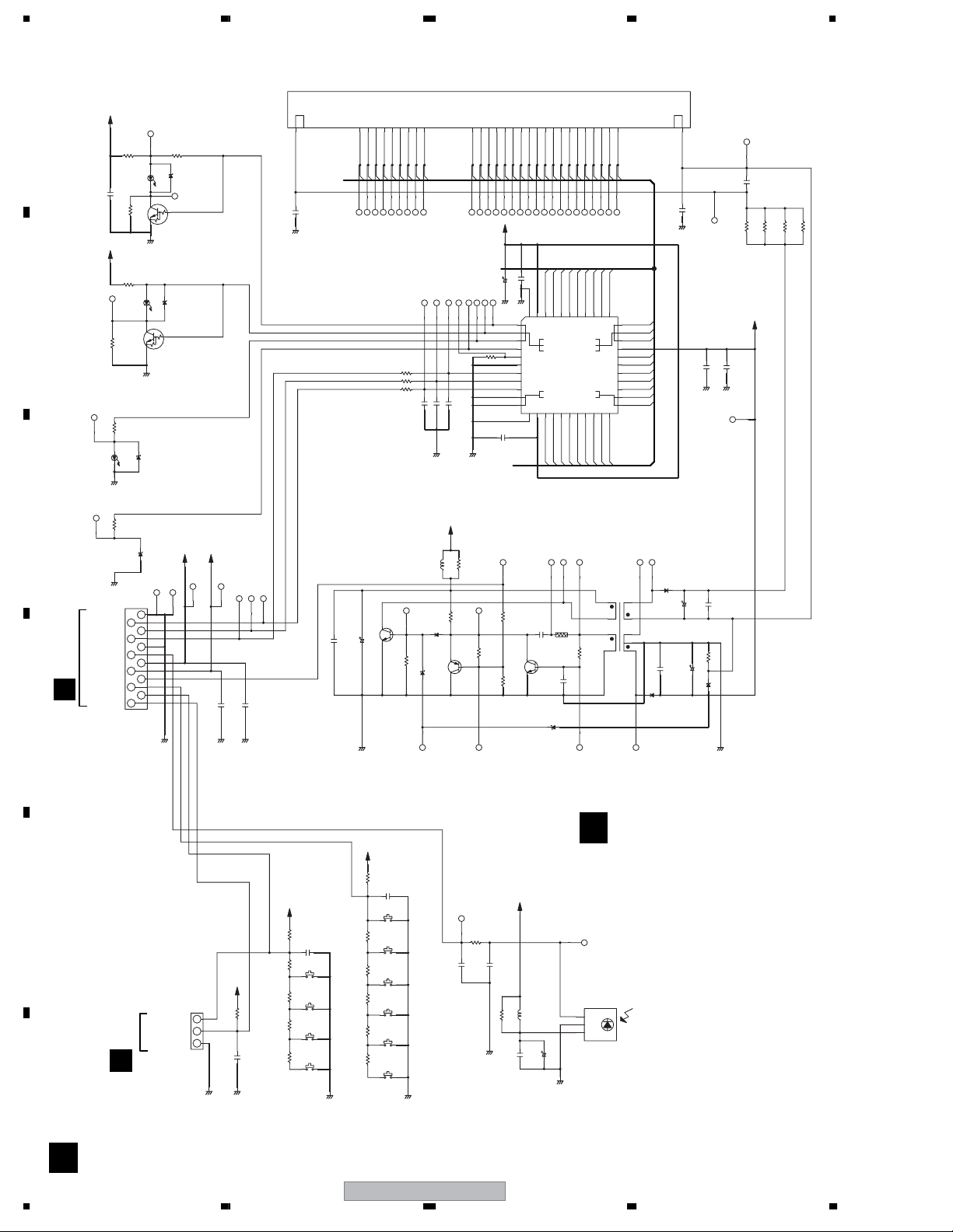
1234
3.8 FJKB, FLKY and KEYB ASSYS
C7038
V7001
1
2
C7003
0.01/50YB
GND
***
10911 1413 17 23161512 26 27 2824 25 31 3229 30 35 363433 393837 4140 49
P1P2P3
P4P7P6P5P8
C7020
P9
R7011
47
R7012
47
R7013
47
***
C7011
L7001
Q7003
C
E
0.1
2SC5712-TLB
C7017
100/16
GND
D7004
B
1SS355-TRB
27k
R7019
D7005
2SA1576A(QR)-TLB
UDZS15(B)-TRB
***
C7013
C7012
V+12V
22
LAU220J-TA
R7016
E
C
***
R7015
270k
B
Q7004
P11
P10
P12
P13
P14
P159G10G
P16
11G
12G8G7G6G5G4G1G2G3G
V+5F
0.1
2G1G3G5G4G6G7G8G9G
***
C7007
C7006
GND GND
43 4244 41 383940
1
VDD
VSS
2
GRID1
GRID6
GRID5
GRID4
GRID2
LED1
LED2
LED4
LED3
OSC
DOUT
DIN
CLK
STB
KEY1
KEY2
VDD
VSS
SEG1
13 1412 15 181716
P1P2P3
C7018
0.022YB
(2125)
C
Q7005
B
E
D7008
UDZS13(B)-TRB
SEG2
R7018
220
GRID3
IC7001
PT6315
SEG3
C7023
GRID10
GRID11
GRID12
SEG11
SEG10
SEG6
SEG5
SEG4
P4P5P6P9P8
1.2k
R7022
0.01YB
3
4
R7014
5
82k
6
7
8
9
10
11
C7014
0.1
GNDGND
FL_F
***
1k
R7017
2SC4081(QR)-TLB
10k
R7020
1.0k
R7021
36 343537
GRID7
GRID8
GRID9
VEE
SEG16
SEG15
SEG14
SEG13
SEG12
SEG7
SEG8
SEG9
20 222119
P7
T7001
VTT1171-A
91
8
73
645
33
32
31
30
29
28
27
26
25
24
23
2
10G
11G
12G
P16
P15
P14
P13
P12
P11
P10
D7003
RF101L2S-TRB
***
C7022
D7007
RF101L2S-TRB
48
***
C7005
C7004
0.01/50YB
GND
C7008
GND GND
C7019
C7016
100/10
R7023
C7021
10/50
D7006
R7007
FL-28V
***
C7009
0.1/50
FLDC+
***
FLDC-
10k
FL-28V
UDZS2R4(B)-TRB
GND
0
***
***
R7009
R7010
***
R7008
FLKB
A
B
C
D
V+12V
C7001
V+12V
R7006
R7053
D7014
GND
R7059
GND
GND
FLSTB
FLCLK
FLDATA
GND
IR
V+5F
V+12R1E
CN7302
to JAKB
FLPON
KEY1
KEY2
C
KEY3
R7002
1.8k
0.1
R7004
R7003
***
180
***
***
180
CN7001
9604S-12C
2
4
6
8
10
12
D7001
SLR-343BBT(FGHJ)
C
B
***
E
GND
D7013
D7002
SLR-343DC(NPQ)-TS
C
B
E
Q7002
***
GND
***
D7015
SATA LED ( YELLOW )
***
D7017
1
3
5
7
9
11
GND GNDGND
HDD LED (BLUE)
R7001
***
***
D7012
Q7001
DVD LED (AMBER)
***
HDMI LED
V+5F
V+12V
C7015
0.1
DC-DC Convertor
IR
KEY1
KEY2
KEY3
E
V+5F
J7001
***
PF03PG-B05
KEY2
KEY3
CN7201
to KEYB
E
GND
1
2
3
GND GND
R7045
C7029
V+5F
10K
R7026
C7028
0.1
S7007
2.2K
R7037
Open/Close
S7008
2.2K
R7039
R7041 R7040
-
S7009
3.3K
+
S7010
5.6K
Play
***
***
F
V+5F
R7038
Pause Live TV
R7027
0.90V
R7028
R7042
1.53V
2.18V
R7044 R7043
2.85V
GND
KEY MATRIX
10K
C7034
0.1
S7002
2.2K
S7001
HDD/DVD
S7003
2.2K
Stop
3.3K
S7004
REC Mode
S7005
5.6K
REC Stop
12K
S7006
REC
V+5F
0V
R7024
C7024
0
***
***
C7025
0
***
R7025
L7002
LAU***J-TA
GND
0.1
C7026
C7027
100/10
GND
0.90V
1.53V
2.18V
2.85V
3.58V
GND
FLKY ASSY
D
(VXX3111)
IC7002
RPM7140-H9
1
Vout
2
GND
3
Vcc
SWITCHES
S7001 : HDD / DVD
S7002 : Pause Live TV
S7003 : Stop
S7004 : Rec Mode
S7005 : Rec Stop
S7006 : REC
S7007 : Open / Close
S7008 : S7009 : +
S7010 : Play
S7001-S7010: VSG1024-A-T
D
30
1234
DVR-640H-AV
Page 31

5678
A
KEYB ASSY
E
(VXX3112)
B3B-PH-K-S
KEY2
D
from FLKB
KEY3
GND
J7001
FJKB ASSY
C
(VXX3113)
9604S-23C(IRISO)
HLEM23S-1(FCI)
GND
FLSTB
FLCLK
FLDATA
GND
IR
V+5F
V+12R1E
FLPON
KEY1
KEY2
CN101
KEY3
to TUJB
2R
GND
2L
GND
A 1/3
2V
GND
2Y
GND
SDET2
GND
2C
CN7201
1
2
3
CN7301
23
22
21
20
19
18
17
16
15
14
13
12
11
10
9
8
7
6
5
4
3
2
1
C7201
Standby/On
GND
GND
***
S7201
GND
0V
V+12R1E
C7306
GND GND
SWITCHES
S7201 : Standby / On
C7202
***
S7202
***
0V
TV Guide
S7203
***
***
0.90V
Left
S7204
***
R7202 R7201
***
1.53V
Right
S7205
***
R7203
***
2.18V
Down
S7206
***
R7204
***
2.85V
Up
S7207
***
R7205
***
3.58V
Enter
GND
KEY MATRIX
S7201-S7207: VSG1024-A-T
CN7302
9604S-12C(IRISO)
V+12R1E
V+5F
V+5F
***
***
C7307
D7301-7304:
UMZ6R8N-TLB
C7302
470p
***
R7308
C7305
GND GND GND
C7304
R7305
***
0
R7301
C7301
GND
R7303
***0***
R7302
*** ***
GND
R7306
C7303
***
12
3123123
D7302D7301 D7303
470p
1122
33
D7304 D7305
***
GND
GND GND GND
R7304
R7307
HLEM12S-1(FCI)
GND
12
FLSTB
11
FLCLK
10
FLDATA
9
GND
8
IR
7
V+5F
6
V+12R1E
GND
JA7301
AKP1238-B
3
4
6
5
FLPON
4
KEY1
3
KEY2
2
KEY3
1
1
S
5
2
from FLKB
CN7001
D
FRONT INPUT JACK
JA7302
VKB1208-
6
5
0
4
7
***
VIDEO
3
Lch
/MONO
2
Rch
1
VNF1084- -T
KN7301
B
C
D
E
56
DVR-640H-AV
F
EC
31
7
8
Page 32

1234
3.9 MAIN ASSY(1/4)
A
B
C
D
E
F
32
F 1/4
F 1/4
MAIN ASSY
V+3FE
(VXX3157 : DVR-640H-AV)
(VXX3159 : DVR-540H-S)
CN101
TP177
50
TD
TP175
49
TR
TP173
48
FD
TP171
47
FR
TP187
46
SCLK
TP184
45
SEN
TP183
44
SDIO
TP182
43
VPP
TP181
42
RESET
TP190
41
RXW
TP179
40
VD3V
TP196
39
GNDD
TP193
38
TEMP
TP192
37
S1
TP195
36
S2
TP194
35
M1
TP100
34
M2
TP101
33
WRF
TP102
32
WPP2
31
VREFPD
TP103
30
WPP1
TP170
29
RF-
TP166 TP167
28
GNDS
TP165
27
RF+
TP104
26
VA5V
TP162
25
M3
TP105
24
M4
TP161
23
S3
TP148
22
S4
TP146
21
GNDS
For Pick-Up
20
VA5V
TP154
DKN1404-A-TBB
19
VREFFM
TP151
18
FMO
17
OSCEN-
16
OSCEN+
15
W3EN+
14
W3EN-
13
W2EN+
12
W2EN-
11
W1EN+
10
W1EN-
TP143
9
RDIS
TP142
8
W3SET
TP141
7
W2SET
TP140
6
W1SET
TP150
5
RSET
TP153
4
VO5V
3
VO5V
TP152
2
GNDO
1
GNDO
TP503
4
ST2+
TP504
3
ST2-
TP505
2
ST1-
TP506
1
ST1+
DKN1288-
For StepperFor FRONTFor SPDL
CN502
TP610
5
LPS2
TP609
4
GNDD
TP607
3
LPS1
TP606
2
BLACK
TP605
1
RED
DKN1402-A
CN601
TP518
12
VCC
TP517
11
HU+
TP516
10
HU-
TP515
9
HV+
TP514
8
HV-
TP513
7
HW+
TP512
6
HW-
TP511
5
HB
TP510
4
U
TP509
3
V
TP508
DKN1312-A-TFB
2
W
TP507
1
GNDD
CN501
GNDO
R168
102
C189
GNDD
GNDD
GNDO
R164
ST2_P
ST2_M
ST1_M
ST1_P
1234
V+5M
SCLK
SCS4
SIO
0R0
0R0
13 14
11
T_M
T_P
F_M
F_P
PUTEMP
12
RF_P
RF_M
WPP2
WPP1
A
B
C
S1
D
S2
C
D
S4
WPP2
S3
S1
WPP1
S2
RF_M
RF_P
A
B
S3
FMO
S4
APCV
FMO
OSCEN_MOSCEN_M
OSCEN_POSCEN_P
W3EN_PW3EN_P
W3EN_MW3EN_M
W2EN_PW2EN_P
W2EN_M
W1EN_PW1EN_P
W1EN_MW1EN_M
R165
R166
R167
APCV
332
R171
R172
V+3D
103
103
R601
R602
LD_M
LD_P
HU_P
HU_M
HV_P
HV_M
HW_P
HW_M
HB
U
V
W
DVR-640H-AV
XRST
WLDON
C187
332
R603
R604
WRF
GNDS
103
C183
C165
102
102
102
R115
0R0
475/6R3
F 2/4
VREF21
C188
V+5L
R147
GNDS
C153
102
102
103
GNDS
0R0
RDIS
W3SET
W2SET
W1SET
475/6R3
OPEN
CLOSE
R142
R143
TP197
C181
C112
GNDS
L112
C184
GNDO
475/6R3
R101
104
C178
GNDO
BTH1103-A
475/6R3
101
101
0R0
475/6R3
V+5L
VREF2
V+12M
V+5M
R102
R112
474
V+3A
C116
102
C101
C102
PUTEMP
R181
4701
474/10
474/10
333
C175
(YB)
104
R130
R124
0R0
182
R123
241
Page 33

5678
54
IC501
HU_P
V+5S
L106
BTH1103-A
(YB)
C172
L107
BTH1103-A
104
106
C118
C167
WRF
10
11
12
13
14
15
16
17
18
19
20
21
22
23
24
25
26
27
28
29
30
C107
1
2
3
4
5
6
7
8
9
106
104
120
WPP1
WPP2
GND1
A1
B1
C1
D1
VCC2
REFI2
REFO1
E1
F1
G1/FOP
H1/FOM
GND2
HPAD
CAD
HPBC
CBC
GND3
PDIN
FPDVREF
APCPH
RREF
31
C119
TP133
TP132
118
119
103
R174
0R0
C103
C104
C105
C108
C109
C110
C111
C113
C114
C115
C117
C168
DCG1029-A-T
V+5S
475/6R3
104
104
475/6R3
331
334
331
334
332
822
104
GNDS
R103
((DCH1201)
((DCH1201)
474
V+3FE V+3A
R117
104
C501
106/16
C502
0R0
ST1_M
ST1_P
38
AGND39GND640GND741GND842GND9
DCH1165-A-T
W
GNDS
F_M
F_P
T_M
T_P
TDRV
FDRV
390
620
473
273
C510
R515
R516
C503
104
49
51
52
VCC
LDO-50LDO+
TKIN53FCIN
DVCC
HU+1HU-2HV+3HV-
HW+6HW-7HB8PGND19U10SPVM111V12GND113GND214GND315GND416GND517PGND218W19SPVM220SPRNF21FG22CTL123CTL224SPIN25DGND26LDIN27VC
4
5
HU_M
HV_P
HV_M
HW_P
HW_M
C505
104
43
44
45
AVM
FCO-46FCO+47TKO-48TKO+
GND10
105
C511
DCN1160
DCN1162
R501
HB
R502
U
V
56
TP131
TP188
117
WRFMON
RFN
116
GND0
RFP
TP134
115
SWRF2
TP135
114
SWRF1
113
VCC1
MONI1
TP130
C164
RFO
MONI2
104
C161
C162
C163
101
103
109
110
111
112
VCC9
CDPDB
CDPDA
AGCIN
MONI3
101
108
C160
101
107
CDPDRF
C159
CDPDC
101
106
C158
CDPDD
TP129
(YB)
104
C156
C154
622
101
C157
105/1 0
104
105
CEQ
GND9
683
C155
475/6R3
R110
R114
99
100
101
102
103
REQ
GND8
CAGC2
CAGC1
IC101
UPC3345GC-YEB
ROPC2/VFOEP/OPCTRG
RF IF
RLD
RLDM
VCC3
WREF32WLD33WLDM
PELD
P2LD36CREG137REFO338REFI39REFO240VCC441ADO42BCO43GND444CDAC45VCC546BCIN47ADIN48CBHWBL49CBHLPP50GND551OUTP152RST53SCK54SO55SI56CP
34
35
104
475/6R3
475/6R3
475/6R3
TP138
C121
C122
C123
C124
TP106
TP201
VREF2
W2SET XRST
W3SET
W1SET
SL2
R507
102
2R0
28
29
R510
SLIN230SLVDD
SLRNF1
C532
473
R505
SL1
393
TP107
MDRV
R506
102
SLIN1
BD7997FS
GNDM
ST2_P
ST2_M
33
102
R517
FG
C152
C504
SPCNF34SLO2-35SLO2+36SLO1-37SLO1+
104
32
102
R503
475/6R3
2R0
31
R511
SLRNF2
102
R504
ROPC1/VFOFP/TLIGHT
SHAPCW/AGCEN
SHAPCRE/AGCFAST
104
104
104
103
103
475/6R3
C125
C126
C127
C128
C129
C130
V+5D
D101
R148
SML-310YT
103
R150
GNDD
LO
XDMUTE2
XDMUTE1
GNDM
9
10
DVR-640H-AV
SHSV/IDGATE
331
V+3D
R240
R254
HDATA0
TP128
C150
104
102
C151
681
94
95
96
97
98
VCC8
CMIRR
RFEQOP
RFEQON
CAMIRR
CRC
CBPD92CBBD
CDEF2
VCC7
CI D
MIRR/RAMWR
LPP/RHEAD/OPID
OPID/OUTP3
VCC658WLDON59OPCTRG/WAGCHLD
SHWB/LOWZ
57
101
R128
C132
SCLK
SCS0
SIO
n
V+3D
R129
472
6587
103
2143
6587
473
2143
HDATA1
HDATA6
HDATA2
7
C147
R111
R144
C148
332
472
93
CDEF
AWOBBLE
OUTP2/LG
RECD/IPID
104
HADRS9
C145
C146
473
222
332
91
FE
PPALL
TE
TE2
TECIN
GND7
CWHP
CWAGC
VCC33
HOLD
FOK
TEC
SGND
EQCK2
EQCK1
GND6
60
TP109
OPCTRG
SHWBSHWB
XRESET
TX_FE
RX_FE
R116
222
102
C144
90
C143
89
C142
88
87
86
85
84
C138
83
82
81
C137
80
C136
79
78
77
76
75
74
73
72
71
70
69
68
67
66
65
64
63
62
61
TP110
WLDON
F 2/4
C169
GNDS
R108
0R0
C135
R175
V+3D
R281
R280
474/10
473
220
104
104
103
682
182
390
475/6R3
473
C133
GNDD
GNDD
(GNDS)
C141
331
C139
331
TP115
TP114
TP113
TP112
TP111
R133
0R0
475/6R3
R118
102
TP155
TP174
TP5757
TP5759
TP5761
TP5762
RFEQO_P
RFEQO_N
390
C171
GNDS
R145
0R0
222
R109
222
R107
R146
0R0
TP123
MIRR_RAMWR
LPP_OPID
IPID_REC DIPID_REC D
SHAPCRE
V+5D
CN401
TP250
TP251
TP252
TP253
TP254
GNDD
SWRF2
SWRF1
FE
PPALL
TE
HOLD
FOK
TEC
LG
EQCK2
EQCK1
ROPC2
ROPC1
SHAPCW
SHSV
1
2
3
4
5
6
7
8
9
10
AWOBBLE
TP119
TP120
TP121
TP122
TP139
TP118
TP117
TP116
NC(SW0)
A9
D6(AG)
D1(SL)
D0(MA)
GND
XREST
TX_FE
RX_FE
V+3D
F 1/4
8
A
B
C
D
E
10FHJ-SM1-TB
F
33
Page 34

1234
3.10 MAIN ASSY(2/4)
A
V+3D
STBY
CN1401
1
TRST
2
EJSNGEN
3
TDI
4
GND
5
TDO
6
DINTEN
7
TMS
8
GND
9
TCK
EJTAG
10
GND
11
RST
12
JTSEL
B
13
DINT
14
V+3
TP5748
R1401
220
TP5749
R1414
220
TP5750
R1402
220
TP5765
TP5751
R1403
220
TP5752
R1404
220
TP5753
R1405
220
TP5766
R1415
220
TP5754
R1406
220
TP5767
R1416
220
TP5755
R1407
220
TP5756
14FHJ-SM1
GNDD
HADRS5
HADRS4
HADRS16
103
R1412
R1401 22 NM
R1410
R1406 NM22
V+3D
0R0
R1813
105
221
C1811
R1811
GNDD
R1814
R1812
L1811
150
330
331
101
473
V+3D
0R0
R1803
105
C1801
GNDD
R1804
330
221
473
V_ADC
C1014
VPVDD
C1008
2SA1576A(QR)
Q1811
GNDD
221
R1801
R1802
331
2SA1576A(QR)
Q1801
GNDD
102
105
221/4
C1016
C1015
106
102
105
C1010
C1009
151
C1812
C1813
C1814
2143
103
R1411
6587
JTMRST
JTDI
JTDO
JTMS
JTCL
NM 22
JTRST
JTRST_FE
EDINT
473
103
R1413
R1417
(FE)
R1410
emulator
(BE)
NM
V+3V
1R5V
3
DTL1106-A
3
DTL1106-A
L1801
390
331
C1802
L1006
2
GNDD
L1004
2
GNDD
NM
C1803
C1804
1
1
F
XRESET
RKN1048
3/4
YI
RS-232C
STBY
CN1402
1
TXD
2
RXD
3
DTR
4
CTS
5
V+5D
6
GNDD
7
C1901
R1902
CI
180
16
TP1407
V+3D
V+5D
103
NM
NM
232RST
3/4
GNDD
R1017
R1016
103
DVRST_RFEXLL
LLRST_DVINT2
R1421
GNDD
103
105
C1421
TX0
R1018
103
ADPOW_DVINT1ADPOW_DVINT1
103
R1422
RXD
RX0
DVR-540H-S Only
GNDD
USBRST_SDA
3R3V
R1019
R1020
GNDD
V+1R5
L1001
DTL1106-A
1
R1002
0R0
V+DDR
L100
V+3D
L1003
DTL1106-A
1
102
103
1R5V
3
2
104
C1002
221/4
C1001
GNDD
2R5V
104
C1004
221/4
C1003
GNDD
3R3V
3
2
C1007
221/4
C1005
GNDD
104
DVR-640H-AV Only
TP1405
TP1404
R1423
R1424
TP1406
TP1411
TP8
TP9
TP10
F
150
C1902
X1001
VSS1192
24.576MHz
NM
C
D
E
F
34
2/4
F
SPDIFO
ADCCLKO
3R3V
VREF_V
DACCLKO
103
R1045
GOUT
103
R1701
D
to HD
GNDD
BOUT
AT1DATA1
ROUT
F
AT1DATA5
AT1DATA3
AT1DATA0
AT1DATA4
3/4
AT1DATA6
AT1DATA7
AT1DATA8
AT1DATA10
AT1DATA9
AT1DATA14
AT1DATA13
AT1DATA11
AT1DATA12
AT1DIOR
AT1DIOW
AT1ADR1_DVINT2
AT1ADR0_DVINT1
AT1CS0
F 2/4
VREF_D
ADATAO
LRCKO
COUT
BCKO
YOUT
BCKI
XRESET
LRCKI
ADATAI
V+3V V_ENC
3
DTL1106-A
1R5V
3
DTL1106-A
R1056
R1057
TP5763
L1008
2
GNDD
L1007
2
GNDD
TP615
TP616
DCLKNO
DADRS10
DADRS1
DADRS0
DCLKO
DADRS9
DADRS2
DWE
DBA1
DDATA12
DDATA31
DCS
DCKE
DBA0
DDATA28
DADRS8
DADRS7
DRAS
DDATA26
DDATA30
DADRS12
VREF_D
DDATA27
DDQS3
DDATA29
DDATA16
DCAS
DDM3
DDATA24
DDATA25
DDATA18
DDATA17
DDM2
DDQS2
DDATA20
DDATA19
DDATA22
DDATA21
DDATA23
220
220
1
1
R1054
9100
R1703
105
C1024
C1020
PVDD
C1017
102
C1025
GNDD
221/4
C1021
106
C1018
to DDR SDRAM
DDM0
DDM1
DDQS1
DDQS0
DDATA9
DDATA8
DDATA7
DADRS3
DADRS4
DADRS6
DADRS5
D21 E21 F21 G21 H21 J21 K21 L21 M21 N21 P21 R21 T21 U21 V21 W21 Y21 AA21
C21
A21
B21
A20
A19
A18
A17
A16
A15
A14
A13
A12
R1010
A11
0R0
A10
A9
A8
C1709
103
0R0
A7
R1052
6200
A6
A5
A4
A3
A2
A1
D20 E20 F20 G20 H20 J20 K20 L20 M20 N20 P20 R20 T20 U20 V20 W20 Y20
B20
C20
D19 E19 F19 G19 H19 J19 K19 L19 M19 N19 P19 R19 T19 U19 V19 W19
C19
B19
C18
D18
B18
C17
D17
B17
C16
D16
B16
C15
D15
B15
C14
D14
B14
C13
D13
B13
C12
D12
B12
C11
D11
B11
C10
D10
B10
C9
B9
C8
B8
C7
B7
C6
B6
C5
B5
C4
B4
C3
B3
C2
B2
B1
C1
0.2mm
0.2mm
17
X1002
VSS1191
27MHz
150
180
C1911
C1912
GNDD
102
105
C1022
102
105
C1019
DDATA4
DDATA0
DDATA2
DDATA1
DDATA3
DDATA5
DDATA6
DDATA11
DDATA13
DDATA14
DADRS11
DDATA15
DDATA10
E18 F18 G18 H18 J18 K18 L18 M18 N18 P18 R18 T18 U18 V18
F17 G17 H17 J17 K17 L17 M17 N17 P17 R17 T17 U17
E17
E16
104
102
105
C1048
C1046
C1047
C1049
102
E15
E14
E13
E12
E11
E10
E9
D9
E8
D8
E7
D7
E6
D6
E5
D5
1R5V
C1052
3R3V
105
C1053
104
C1062
105
C1063
C1050
104
104
C1064
C1051
102
104
C1066
104
C1054
102
C1056
104
DVDR IC (EMMA2)
C1055
105
C1057
102
105
C1067
C1065
102
J13 K13 L13 M13 N13
J12 K12 L12 M12 N12
J11 K11 L11 M11 N11
J10 K10 L10 M10 N10
J9 K9 L9 M9 N9
GNDD
D4
AT1BUFDIR
TP617
AT1DATA2
AT1DATA15
AT1ADR2
AT1INTRQ
AT1DMACK
AT1DMARQ
AT1CS1
AT1IORDY
AT1RESET
102
C1081
R1061
GNDD
15
R258
100
DSS1152-A
1
0R0
X201
16.93MHz
GNDD
CLOSE
TX_FE
EQCK1
XDMUTE2
R202
822
3
2
R259
331
V+3FE
VREF2
AWOBBLE
GNDD
(GNDS)
R1001
0R0
221/4
C1071
GNDD
0R0
R1705
100/16
104
104
C1707
C1701
C1708
2R5V
104
105
C1045
C1044
IC100 1
UPD61272F1-107KA3A- K
TP1012
PPALL
SWRF1
JTRST_FE
FE
MIRR_RAMWR
RX_FELGOPEN
LEMSW
XDMUTE1
104
103
R256
C1082
GNDD
TP1013
0R0
R1003
0R0
R1004
0R0
R1005
0R0
R1006
1R5V
C1073
L1010
475/6R3
BTH1103-A
221/4
C1074
GNDD
SWRF2
TE
V_AC3
GNDD
C1075
C1026
106
R1704
C1710
104
C1706
(DCH1201)
0R0
104
C1702
TDRV
XRST
104
R1007
R1008
SSMtoT_NSDA
104
C1705
472
C220
SL1
MDRV
103
R208
C236
683
V_EP1
GNDD
C1076
475/6R3
RX1_DV_LL
104
104
C1704
C1703
SL2LOHOLD
GNDD
104
C1029
0R0
0R0
TX1_DV_LL
104
GNDD
FDRV
NSCS
USB_INT
ASCK_NSCK
LLRST_DVINT2
C1070
105
C1069
C1068
102
103
223
C221
C224
FOK
TEC
RT1N141U
GNDD
(GNDS)
ADPOW
IR_GLINK
0R0
DVRST_RFEXLL
R1012
C1061
105
C1060
104
C1059
102
C1058
104
472
C223
IPID_RECD
C260
104
Q101
C261
102
V_WP1
RX2_GLINK
T5R5P5N5M5L5K5J5H5G5F5
R1062
2.
EQCK2
R1015
R1014
103
183
101
101
3R3V
102
104
5R0
GNDD
HADRS22
HDATA13
HADRS1
HADRS21
HADRS0
HADRS17
HADRS19
HADRS20
HDATA14
HADRS18
HDATA12
HDATA0
HADRS16
HADRS7
HADRS2
HADRS12
HADRS10
HADRS3
HDATA15
HADRS4
HADRS8
HDATA8
HADRS5
HADRS6
HDATA1
HADRS15
HDATA2
HDATA3
HDATA5
HADRS9
HADRS14
HDATA7
HDATA4
HDATA9
HADRS13
HDATA6
HDATA11
HDATA10
HADRS11
to FLASH
GCSB
HWS0
HDOE
HCS0
AMUTE
V+3D
473
R203
REMI
TP1011
103
R1013
GNDD
3R3V
FG
V_WP1
105
C296
GNDD
SHAPCRE
W1EN_M
SHWB
ROPC1
5R0
C1087
W1EN_P
ROPC2
SHAPCW
W3EN_M
OSCEN_M
W3EN_P
OSCEN_P
W2EN_P
C231
C230
0R0
R214
223
223
C1043
GNDD
V_LV3
C1040
GNDD
WLDON
F 1/4
R206
222
104
104
V_WP3
C1037
GNDD
104
GNDD
HSMtoT
TX2_GLINK
USBRST_SDA
HSTtoM
X525P_SCL
JTMS
JTCL
JTDI
JTDO
EDINT
JTMRST
SSTtoM
GNDD
AA20
Y19
AA19
Y18
W18
AA18
V17
Y17
W17
AA17
V16
V15
V14
V13
V12
V11
V10
V9
V8
V7
V6
V5
V4
V3U3T3R3P3N3M3L3K3J3H3G3F3E3D3
2.
471
C233
RFEQO_N
W16
W15
W14
W13
W12
W11
W10
W9
W8
W7
W6
W5
W4
W3
SIO
SCS0
SCLK
V_EP3
104
C1034
GNDD
V_LV3
V_WP3
Y16
AA16
Y15
AA15
Y14
AA14
Y13
AA13
Y12
AA12
Y11
AA11
R273
Y10
AA10
Y9
AA9
680
C264
Y8
AA8
681
C297
Y7
AA7
R245
Y6
AA6
R1064
Y5
AA5
R1063
Y4
AA4
5R0
C1085
AA3
AA2
C1086
Y3
Y2W2V2U2T2R2P2N2M2L2K2J2H2G2F2E2D2
AA1Y1W1V1U1T1R1P1N1M1L1K1J1H1G1F1E1D1
C1084
5R0
GNDD
(GNDS)
SCS4
W2EN_M
RDIS
473
473
R210
R216
GNDD
U16
U15
U14
U13
U12
U11
U10
U9
U8
U7
U6
U5
U4T4R4P4N4M4L4K4J4H4G4F4E4
2.
471
C232
221
OPCTRG
SHSV
LPP_OPID
RFEQO_P
DVR-640H-AV
1234
Page 35

5678
V+3D
103
R1117
HDATA15
V+3D
103
R1118
HDATA8
V+3D
103
R1120
HDATA9
V+3D
103
R1122
HDATA10
HDATA11
103
R1125
GNDD
V+3V
4700
R1301
2
104
1001
C1302
R1302
3
104
1001
C1303
R1303
IC1301
NJM12904V
GNDD
V+DDR
6
104
1001
C1312
R1312
5
NM
104
1001
IC1301
C1313
R1313
GNDD
NJM12904V
R1281
DADRS5
DADRS9
6587
DADRS0
DADRS1
R1282
DADRS4
DADRS10
6587
DADRS3
R1283
DADRS11
6587
DADRS7
DADRS8
R1284
DADRS12
R1285
DBA0
DBA1
R1286
R1287
DWE
DRAS
6587
DCAS
R1288
DCLKO TCLKOTCLKO
DCLKNO
R1289
3R3V
R1151
103
R1152
103
R1153
103
R1154
103
R1175
473
R1156
473
R1157
103
R1159
103
103
R1161
R1162
473
R1176
R1163
103
R1164
103
R1165
103
103
R1167
R1168
103
R1169
103
R1170
473
103
R1172
R1173
103
R1174
103
3R3V
R1181
103
R1182
103
R1183
103
R1184
103
V+5D
GNDD
DCKE
R1219
C1215
151/4(VCH1246-)
C1204
105
66
VSS3
65
VSSQ5
VDDQ5
VSSQ4
VDDQ4
VSSQ3
VSSQ5
VDDQ5
VSSQ4
VDDQ4
VSSQ3
DQ15
64
63
DQ14
62
DQ13
61
60
DQ12
59
DQ11
58
57
DQ10
56
DQ9
55
54
DQ8
53
NC6
52
51
UDQS
50
NC5
49
VREF
48
VSS2
47
UDM
46
/CK
45
CK
44
CKE
43
NC4
42
A12
41
A11
40
A9
39
A8
38
A7
37
A6
36
A5
35
A4
66
VSS3
65
DQ15
64
63
DQ14
62
DQ13
61
60
DQ12
59
DQ11
58
57
DQ10
56
DQ9
55
54
DQ8
53
NC6
52
51
UDQS
50
NC5
49
VREF
48
VSS2
47
UDM
46
/CK
45
CK
44
CKE
43
NC4
42
A12
41
A11
40
A9
39
A8
38
A7
37
A6
36
A5
35
A4
R1255
6587
C1205
103
330
R1256
6587
C1210
102
330
R1257
C1213
330
104
R1258
330
C1211
104
C1223
105
R1273
67
C1224
103
330
R1274
6587
C1229
102
330
R1275
C1214
330
104
R1276
330
C1230
104
HDATA12
103
R1116
GNDD
HADRS16
HADRS15
HADRS14
HADRS13
HADRS12
HADRS11
HADRS10
HADRS9
HADRS22HADRS22
HADRS20
R1107
HADRS21
HWS0
XRESET
R1110
HADRS19
HADRS18
HADRS8
HADRS7
HADRS6
HADRS5
HADRS4
HADRS3
VWV2216- /V,VWV2233- /V :VYW2366- /V
TP202
8
1
VREF_V
4
TP203
R1314
7
VREF_D
0R0
TADRS5
TADRS9
TADRS0
2323
TADRS1
14
560
560
560
560
560
560
560
330
330
2143
TADRS10
TADRS11
14
TADRS12
2143
TADRS4
TADRS6DADRS6
TADRS3
TADRS2DADRS2
TADRS7
TADRS8
1
2
3
4
5
6
7
8
9
10
0R0
11
12
13
0R0
14
15
16
17
18
19
20
21
22
23
24
S29GL064M90TCIR20-K
VWV2215- /V :VYW2365- /V
DDATA0
DDATA1
DDATA2
DDATA3
DDATA4
DDATA5
DDATA6
DDATA7
DDQS0
DDM0
TWE
TCAS
TRAS
TCS
TBA0
TBA1
TADRS10
TADRS0
TADRS1
TADRS2
TADRS3
DDATA16
DDATA17
DDATA18
DDATA19
DDATA20
DDATA21
DDATA22
DDATA23
DDQS2
DDM2
TWE
TCAS
TRAS
TCS
TBA0
TBA1
TADRS10
TBA0TBA0
TADRS0
TBA1TBA1
TADRS1
TADRS2
TADRS3
TWE
TCSDCS
TRAS
TCAS
R1103
0R0
A15
A14
A13
A12
A11
A10
A9
A8
A19
A20
WE
RESET
A21
WP/ACC
RY/BY
A18
A17
A7
A6
A5
A4
A3
A2
A1
IC1102
FLASH
DQ15/A-1
TP1111
HDOE
HCS0
104
C1212
6587
6587
6587
6587
HADRS0
HADRS1
HADRS2
HADRS3
HADRS4
HADRS5
HADRS6
HADRS7
HADRS8
HADRS9
HADRS10
HADRS11
HADRS12
HADRS13
HADRS14
HADRS15
HADRS16
HADRS17
HADRS18
HADRS19
HDOE
HWS0
HCS0
GCSB
C1235
K4H511638C-UCB3
221/4
HY5DU121622CTP-J
C1202
1
105
2
C1203
3
4
104
5
6
7
8
C1206
9
103
10
11
12
13
14
C1207
15
102
16
17
C1208
18
105
19
20
21
22
23
24
25
26
27
28
29
30
31
32
C1209
33
102
K4H511638C-UCB3
HY5DU121622CTP-J
C1221
1
105
2
C1222
3
4
104
5
6
7
8
C1225
9
103
10
11
12
13
14
C1226
15
102
16
17
C1227
18
105
19
20
21
22
23
24
25
26
27
28
29
30
31
32
C1228
33
102
IC1201
Clock:166MHz
VDD1
DQ0
VDDQ1
DQ1
DQ2
VSSQ1
DQ3
DQ4
VDDQ2
DQ5
DQ6
VSSQ2
DQ7
NC1
VDDQ3
LDQS
NC2
VDD2
NC
LDM
/WE
/CAS
/RAS
/CS
NC3
BA0
BA1
A10/AP
A0
A1
A2
A3
VDD334VSS1
IC1221
VDD1
DQ0
VDDQ1
DQ1
DQ2
VSSQ1
DQ3
DQ4
VDDQ2
DQ5
DQ6
VSSQ2
DQ7
NC1
VDDQ3
LDQS
NC2
VDD2
NC
LDM
/WE
/CAS
/RAS
/CS
NC3
BA0
BA1
A10/AP
A0
A1
A2
A3
VDD334VSS1
PROTECT
3R3V
103
R1114
104
C1105
48
A16
47
BYTE
46
VSS2
45
44
DQ7
43
DQ14
42
DQ6
41
DQ13
40
DQ5
39
DQ12
38
DQ4
C1113
37
VCC
36
105
DQ11
35
DQ3
34
DQ10
33
DQ2
32
DQ9
31
DQ1
30
DQ8
29
DQ0
R1127
28
OE
27
470
VSS1
26
CE
25
A0
HADRS17
HDATA15
HDATA7
HDATA14
HDATA6
HDATA13
HDATA5
HDATA12
HDATA4
HDATA11
HDATA3
HDATA10
HDATA2
HDATA9
HDATA1
HDATA8
HDATA0
HADRS1HADRS2
GNDD
R1241
2143
560
R1242
2143
560
R1243
560
R1244
560
R1261
2143
560
R1262
2143
560
R1263
560
R1264
560
V+2R5
6587
6587
6587
6587
L1201
DTL1106- A
3
2
1
V+DDR
R1245
2143
330
R1246
2143
330
R1247
330
R1240
330
R1265
2143
330
R1266
2143
330
R1267
330
R1260
330
TP614
GNDD
DVR-640H-AV
56
R3832
RAB4CQ223J-T
RAB4CQ223J-T
RAB4CQ223J-T
RAB4CQ223J-T
RAB4CQ223J-T
RAB4CQ223J-T
2143
2143
VREF_D
2143
2143
VREF_D
NM
R3833
C3801
GNDD
V+3D
0R0
105
R3801
223
R3802
223
R3803
223
R3804
223
R3805
223
R3806
223
F 2/4
105
R3831
C3802
223
6587
6587
6587
6587
6587
AT1ADR1_DVINT2
AT1ADR0_DVINT1
6587
R3807
223
R1248
DDATA15
DDATA14
6587
DDATA13
2143
DDATA12
560
R1249
DDATA11
DDATA10
6587
2143
560
R1250
560
R1251
560
R1252
330
TADRS12
TADRS11
R1268
DDATA31
DDATA30
2143
DDATA29
6587
DDATA28
560
R1269
DDATA27
DDATA26
2143
DDATA25
6587
DDATA24
560
R1270
560
R1271
560
R1272
330
TADRS12
TADRS11
7
MAIN ASSY
(VXX3157 : DVR-640H-AV)
(VXX3159 : DVR-540H-S)
2143
2143
2143
2143
2143
2143
DCLKEN
AT1RESET
AT1DATA7
AT1DATA8
AT1DATA6
AT1DATA9
AT1DATA5
AT1DATA10
AT1DATA4
AT1DATA11
AT1DATA3
AT1DATA12
AT1DATA2
AT1DATA13
AT1DATA1
AT1DATA14
AT1DATA0
AT1DATA15
AT1DIOW
AT1DIOR
AT1DMACK
AT1ADR2
AT1CS0
AT1CS1
AT1RESET
AT1DATA7
AT1DATA8
AT1DATA6
AT1DATA9
AT1DATA5
AT1DATA10
AT1DATA4
AT1DATA11
AT1DATA3
AT1DATA12
AT1DATA2
AT1DATA13
AT1DATA1
AT1DATA14
AT1DATA0
AT1DATA15
AT1DMARQ
AT1DIOW
AT1DIOR
AT1IORDY
AT1DMACK
AT1INTRQ
AT1ADR1_DVINT2
AT1ADR0_DVINT1
AT1ADR2
AT1CS0
AT1CS1
6587
6587
6587
6587
6587
V+3D
R3814
R3816
R3817
R3818
R3820
R3821
R3823
R3808
330
R3810
330
RAB4CQ330J-T
2143
R3811
330
RAB4CQ330J-T
2143
R3812
330
RAB4CQ330J-T
2143
R3813
330
RAB4CQ330J-T
2143
E-SATA
820
220
R3819
220
102
820
R3822
220
103
820
330
R3830
330
RAB4CQ330J-T
2143
F
DDATA9
DDATA8
DDQS1
TCLKNO
TCLKO
DCLKEN
TADRS9
TADRS8
TADRS7
TADRS6
TADRS5
TADRS4
DDQS3
TCLKNO
TCLKO
DCLKEN
TADRS9
TADRS8
TADRS7
TADRS6
TADRS5
TADRS4
DDM1
DDM3
F 3/4
DV_CIN
DV_YVIN
DVRST_RFEXLL
X525P_SCL
USBRST_SDA
DV_LRCK
DV_BCK
DV_ADATA
ADPOW_DVINT1
LLRST_DVINT2
DV_RST
TX1_DV_LL
RX1_DV_LL
X525P_SCL
USBRST_SDA
0R0
0R0
R3860
R3859
X525P
only
VWV2214- /V
VWV2215- /V
DVR-640H-AV Only
104
C3816
C3815
102
R3863
GNDD
TP3830
TP3831
470
C3809
C3810
R3847
0R0
R3848
0R0
R3855
0R0
R3851
470
R3852
470
V+5D
IC380 2
1
SCL
2
SDA
/RESET
3
A0
4
A1
5
A2
6
I/O0
7
I/O1
8
VSS9I/O2
PCA9557PW
GNDD
104
102
R3862
470
C3808
C3806
GNDD
VDD
I/O7
I/O6
I/O5
I/O4
I/O3
470
R3837
R3815
R3861
R3853
5
6
7
8
R3854
0R0
C3807
V+3DV
104
16
15
14
13
12
11
10
TP5721
TP5722
TP5723
TP5724
TP5725
TP5726
TP5727
TP5728
TP5729
TP5730
TP5732
TP5731
TP5733
TP5734
TP5735
TP5736
TP5737
TP5717
TP5738
TP5739
TP5740
TP5741
TP5742
TP5743
TP5768
TP5764
TP5769
TP5744
TP5745
TP5746
TP5747
TP5720
TP5718
TP5719
0R0
0R0
4
3
2
1
R3856
470
R3857
470
R3858
470
GNDD
C3803
GNDD
V+3D
R3838
GNDD
0R0
562
R3850
0R0
105
C3804
103
R3841
R3836
TP3828
TP3807
TP3809
TP3810
TP3811
V+3DV
TP3813
TP3814
TP3815
TP3816
TP3817
TP3818
TP3819
TP3820
TP3822
TP3823
TP3829
TP3826
TP3827
TP3824
TP3825
105
GND
103
R3842
C3805
TP5770
GNDD
103
GNDD
8
to HDD
CN3801
1
RESET#
2
GND
3
DD7
4
DD8
5
DD6
6
DD9
7
DD5
8
DD10
9
DD4
10
DD11
11
DD3
12
DD12
13
DD2
14
DD13
15
DD1
16
DD14
17
DD0
18
DD15
19
GND
20
KEYPIN
21
DMARQ
105
22
GND
23
DIOW#
24
GND
25
DIOR#
26
GND
27
IORDY
28
CSEL
0R0
29
DMACK#
30
GND
31
INTRQ
32
RESERVED
33
DA1
34
PDIAG#
35
DA0
36
DA2
37
CS0#
38
CS1#
39
DASP#
40
GND
to DVJB
CN3802
C_OUT
1
GND
2
Y_OUT
3
GND
4
VENC_RST
5
SCL
6
SDA
7
GND
8
V+3D
9
GND
10
AMCLKI
11
GND
12
ALRCK
13
ABCK
14
PCM
15
GND
16
DV_INT1
17
DV_INT2
18
DV_RST
19
20
DV_TX
21
DV_RX
V+5D
22
23
V+3D
24
V+3D
GNDD
XRESET
ADPOW
DV_XADC
DV_RST
USB_RST
F 2/4
A
B
VKN2050-A-TFB
C
CN301
J
D
VKN2045-A-TFB
CN101
G
E
F
35
Page 36

1234
3.11 MAIN ASSY(3/4)
A
B
C
D
E
F
36
EV+5.8 V
13
GNDD
12
SW+1.53V
11
SW+1.53V
10
GNDD
9
SW+3.33V
8
SW+3.33V
7
GNDD
6
V+12V
5
S13B-PH-K-S
GND
4
V+5M
3
GNDM
2
V+12M
1
CN2401
CN201
K
BCKO
ADATAO
LRCKO
RCHIN
LCHIN
F 3/4
R2401
TP15TP16
TP11
TP12
GNDD
TP27
TP23
TP19
TP31
TP20
TP24
TP32
TP28
TP33
0R0
TP2420
TP2419
GNDM
TP41
TP43
TP40
TP42
TP44
C2406
C2405
C2404
C2403
C2402
C2401
TP47
TP51
TP52
TP48
TP55
TP56
104
104
104
104
104
104
TP59
TP60
TP2407
TP2402
TP2401
TP2405
TP2406
TP2408
TP2417
TP2403TP2404
TP2418
TP2409
TP2410
IC2402
12
CEK1285
IC2401
12
CEK1285
TP6004
TP6003
TP6007
TP6001
TP6006
TP6005
TP6002
TP6008
TP6009
TP6010
TP6012
TP6011
TP6013
EV+5.8V
V+1R5_IN
SW+3.33V
V+12V
V+5M
V+12M
TP6016
TP6015
TP6017
TP6014
TP6024
TP6021
TP6020
TP6023
TP6022
TP6018
TP6025
TP6019
GNDDGNDDGNDD GNDD
TP6026
V+3D
R4011
682
EV+5.8V
GNDD
TP67
TP68
TP66
R4012
TP69
TP70
R4517
SW+3.33V
EV+5.8V
V+5A
R4522
V+5AVI
0R0
R4527
V+5D
0R0
0R0
0R0
R4524
P_CONT2
R4523
V+5S
0R0
0R0
R4520
475/6R3
R4521
V+5L
EV+5.8V
103
VOUT
100/16
IC4504
ON/OFF
C4507
GNDD
TP65
VIN
103
NC
VSS
C4508
S-1170B50UC-OUJ-TRB
C4509
P_CONT2
TP73
TP71
TP72
GNDD
C4525
C4548
475/6R3
R4515
0R0
475/6R3
R4535
0R0
R4513
R4514
RB501V
5
VOUT
IC4507
1
ON/OFF
GNDD
5
VOUT
IC4511
1
ON/OFF
2NC3
2NC3
4
VSS
4
VSS
0R0
0R0
0R0
VIN
C4526
S-1170B33UC-OTS
VIN
S-1170B33UC-OTS
C4549
475/6R3
475/6R3
TP77
102
C4527
TP78
102
C4550
TP108
V+3V
V+3DV
V+3D
V+3FE
GNDD
C3106
GNDD
V+5A
101/16
V+3D
C3201
GNDD
1
2
3
4
5
6
7
8
C3204
C3205
C3103
C3101
104
C
BE
104
Audio DAC
IC3201
PCM1742KE
BCKIN
DATA
LRCKIN
GND
Vdd
ZEROL
Vcc
ZEROR
VoutL
VoutR9AGND
105
GNDD
E1 B1 C2
MCLK
Vcom
331
16
15
ML
14
MC
13
MD
12
11
10
Audio ADC
1
AINR
2
AINL
3
CKS1
4
VCOM
5
AGND
6
VA
7
VD
8
DGND9SDTO
AK5359ET
(AK5358ET)
B2C1
IC3101
E2
AMUTE
CKS0
CKS2
DIF
PDN
SCLK
MCLK
LRCK
104
C3203
GNDA
16
15
14
13
12
11
10
GNDD
R3217
23
101/16
C3214
18
0R0
19
20
R3229
R3231
R3232
GNDA
R3113
0R0
R3105
0R0
D3201
DAN202U
682
R3214
223
R3215
105
C3102
R3102
470
470
470
V+3D
GNDD
2143
ASCK_NSCK
SSMtoT_NSDA
V+5A
681
R3216
C3216
101/16
AD_ADATA
6587
GNDD
NSCS
R3209
8201
C3209
R3224
8201
ADPOW
AD_BC
K
AD_LRCK
103
AMUTE1
DACCLKO
104
R3234
GNDD
R3208
56R0
104
R3223
56R0
XRESET
DV_XADC
DVR-540H-S only
F
0R0
R3104
V+12V
2/4
R3210
C3208
R3225
C3210
L310 2
R3103
472
681
681
472
3
1
104
0R0
104
C4561
R3207
1502
R3212
R3221
R3226
1502
V+3D
2
TC7SZ126FU
DTL1106- A
4
VCC
5
C3108
Q4561
2SC4081(QR)
R4561
C4562
101
101
IC3102
OUT
GNDD
ADCCLKO
101
104
GNDA
2
3
5
6
GND
IN
G
R3115
AD_LRCK
C4563
GNDA
3
2
1
0R0
DV_LRCK
LRCKI
TP204
101/16
C3207
121
8
1
IC3202
4
UPC4570G2
IC3202
UPC4570G2
7
C3211
121
F
R3110
R3111
0R0
R3116
DV_BCK
BCKI
AD_BCK
V+12A
104
C4565
V+12A
104
C3206
GNDA
R3211
L ch
101
R3222
R ch
101
DVR-640H-AV only
DVAMCLKO
IC3103
TC74VHC157FT
2/4
1
SELECT
2
1A
3
1B
4
1Y
5
470
2A
6
2B
7
2Y
8
470
GND93Y
GNDD
LCHOUT
RCHOUT
V+3D
16
VCC
ST
4A
4B
4Y
3A
3B
105
15
C3107
14
GNDD
13
12
11
10
R3112
0R0
R3117
470
GNDD
DV_ADATA
ADATAI AD_ADATA
R3227
R3228
R3230
V+5A
C3212
GNDA
470
470
470
R3108
0R0
R3109
0R0
102/6R3
C3202
24
25
UMF21N-TLB
C1 B2 E2
E1 B1 C2
104
DVR-640H-AV
1234
Page 37

5678
SW+3.33V
GNDD
P_CONT2
F
2/4
F
C4542
101/16
YOUT
Y_OUT
COUT
C_OUT
from EMMA
GOUT
Yp_OUT
BOUT
Cb_OUT
ROUT
Cr_OUT
2/4
TP79
V+2R5
4
5
VIN
GNDD
2000
2000
0R0
2000
B
B
B
IC4512
1
R2501
R2504
R2507
VOUT
ON/OFF
E
C
E
C
E
C
2NC3
VSS
S-1170B25UC-OTK
V+5AVI
105
C2501
681
2SA1576A(QR)
Q2501
681
2SA1576A(QR)
Q2502
681
2SA1576A(QR)
Q2503
C2506
C4552
101/16
475/6R3
1.002Vpp,SYNC DC??? V
0.2873Vpp,CENTER DC???V
1.002Vpp,SYNC DC??? V
0.7104Vpp,CENTER DC???V
0.7104Vpp,CENTER DC???V
C4551
105/10
R4534
0R0
R2502
GNDD
R2505
R2506
GNDD
R2508
DVR-640H-AV only
681
R2510
2000
2000
E
B
C
R2513
E
B
C
2SA1576A(QR)
Q2504
681
2SA1576A(QR)
Q2505
GNDD
R2213
331
R2206
561
V+5AVI
C2208
IC2201
1
SW
2
OUT
VCC3IN2
MM1503XN
105
6
C2222
IN1
5
105/10
GND
C2221
4
105/10
GNDD
GNDD
R2511
GNDD
R2514
V+5AVI
YI
to EMMA
CI
HSTtoM
SSTtoM
RX0
103
R3707
GNDD
2143
C2210
106
DCH1201-A-T
C2217
106
DCH1201-A-T
6587
Q2205
2SA1576A(QR)-TLB
Q2206
2SA1576A(QR)-TLB
V+5AVI
V+5AVI
R3703
R3704
R3706
R2209
E
C
R2210
E
C
681
B
Y IN
GNDD
681
B
GNDD
R3711
0R0
R2211
GNDD
C IN
V+3D
101
101
101
162
122
C3703
R2214
(VWV2215-)
331
(VWV2216-)
(VWV2233-)
R2208
561
122
R2212
GNDD
TC7WH34FU
2Y
3A
6
1Y
7
VCC
8
IC3701
105
1
2
C2209
162
(DVR-640H)
(DVR-540H
R3732
D3711
D3712
GND
2A
3Y
1A
IC2202
IN1
GND
MM1501XN
105
6
5
4
SW
OUT
VCC3IN2
DVR-540H-S only
562
RB501V
RB501V
RXD
45
3
2
1
GNDD
C2224
103
C2223
GNDD
JTRST
232RST
from 232C
F
103
2/4
GNDD
DVR-640H-AV
56
Y_OUT
C_OUT
YP_OUT
CB_OUT
CR_OUT
J_Y_IN
DV_YVIN
F
2/4
J_C_IN
DV_CIN
F
2/4
XRST1
103
C3701
GNDD
HST_TO_M
DAT_TO_M
104
C2301
102
R2314
GNDD
J_C_I N
J_Y_I N
F
CR_OUT
CB_OUT
YP_OUT
Y_OUT
C_OUT
DV_XADC
XRST1
DAT_TO_M
HST_TO_M
DV_XADC
IR_GLIN K
TX2_GLINK
RX2_GLINK
TX0
R2312
RXD
R2313
2/4
F
F 3/4
V+1R5_IN
104
C2302
AMUTE1
RCHIN
102
R2315
LCHIN
P_CONT2
0.268Vpp,CENTER DC???V
2
1.00Vpp,SYNC DC???V
X525P
2/4
LCHOUT
RCHOUT
SSMtoT_NSDA
HSMtoT
ASCK_NSCK
2143
GNDD
TX1_DV_LL
RX1_DV_LL
LLRST_DVINT2
XRESET
DVRST_RFEXLL
O
F
V+1R5
330
R3715
R3716
NM
R3717
1
OUT
VDD
IC3707
4
NC
GND
GNDD
SPDIFO
7
MAIN ASSY
(VXX3157 : DVR-640-AV)
(VXX3159 : DVR-540H-S)
R4591
22
3
7
4
5
GNDA
105
21
8
6
26
R3005
0R0
0R0
0R0
R2307
R2305
27
V+12V
0R0
0R0
0R0
103
105
R2308
0R0
0R0
0R0
R2302
0R0
R2301
682
103
GNDD
R2304
0R0
105
R3721
R2602
C300
0R0
TP2302
TP2303
TP2304
TP2305
TP2306
GNDD
R3501
471
CN2301
TP89
TP91
TP90
TP2311
TP93
TP92
TP86
TP85
TP84
TP83
TP82
TP81
TP2300
TP88
TP87
TP2309
TP94
TP97
TP99
TP96
TP98
TP95
TP2301
TP2312
TP2313
TP2314
CN2601
TP2602
TP2603
TP2604
TP2605
TP2601
TP2606
GNDD
391
R3502
681
470
R3504
C3501
R3503
GNDD
8
6587
0R0
C3738
2
PST3813U
3
R4592
R4593
1
R3002
R3004
R3003
R2309
R2310
R2311
R2306
R2603
R2604
0R0
R3720
0R0
V+1R5
AMUTE
1
R_IN
2
GND
3
L_I N
4
P_CONT2
5
C_IN
6
GND
7
Y_I N
8
X525P
9
GND
10
CR_OUT
11
GND
12
CB_OUT
13
GND
14
YP_OUT
15
GND
16
Y_OUT
17
GND
18
C_OUT
19
MRST
20
L_OUT
21
GNDA
22
R_OUT
23
SW+12V
24
XRST1
25
DAM_TO_T
26
HSM_TO_T
27
DAT_TO_M
28
ASCK
29
HST_TO_M
30
GND
31
SPDIF
32
B_I R
33
TXDGL
34
RXDGL
35
TX1
1
RX1
2
GND
3
XRESET
4
RFE/XLL
5
GND
6
PCMCLK
7
GND
8
SPDIF
9
GND
10
V+3D
0R0
R3511
105
C3511
GNDD
Q3501
2SC4081(QR)-TLB
R3505
75R0
(F )
151
F 3/4
A
CN401
B
A 2/3
C
from TUJB
VKN1439-A-TBB
D
VKN2038-A-TFB
E
F
37
Page 38

1234
3.12 MAIN ASSY(4/4)
A
B
C
CN5601
TP6TP5TP4TP2TP3 TP1TP7
10
USBDP1
9
GND
8
USBDM1
7
GND
6
USBVFB
CN101
H
D
5
V+5USB
GND
4
3
S10B-PH-K-S
USBDP2
2
GND
1
USBDM2
GNDD
C5512
104
R5509
330
R5508
330
R5507
100
V+5USB
C5506
102
R5605
R5606
0R0
R5608
R5607
330
330
V+3USB
USBDP1
USBDM1
USBVFB
USBDP2
USBDM2
HDATA8
HDATA9
HDATA10
HDATA11
HDATA12
HDATA13
HDATA14
HDATA15
USB_INT
HWS0
HDOE
HADRS1
HADRS2
L5701
2
C5701
V+3D
V+3USB
1
3
DTL1106-A
221/4
GNDD
C5702
TP5701
105
E
F
38
F 4/4
5
6
6
7
7
8
8
IC5631
BD6517F
LM3526M
472
R5612
4
45
3
3
2
2
1
1
R5609
R5610
-L
0R0
0R0
R5611
472
USBXPO
USBXOC
EV+5.8V
V+3D
CN
4
CONT
5
GND
3
SUB
6
NC
2
C5621
105
VIN
7
IC5621
MM1565AF
VO
1
C5622
102
C5623
225
C5624
101/16
GNDD
DVR-640H-AV
1234
Page 39

5678
V+3D
R5713
103
C5721
C5722
2R0
2R0
C5712
C5728
X5701
C5711
105
DCH1201-A-T
(6MHz)
R5722
VSS1210-A
0R0
105
106
F 4/4
MAIN ASSY
A
(VXX3157 : DVR-640H-AV)
(VXX3159 : DVR-540H-S)
This block is only for DVR-640H-AV.
B
105
105
105
103
103
103
VREGOUT
0R0
R5702
106
C5727
DCH1201-A-T
GNDD
C
USB_RST
USB_RST
USBVFB
USBXPO
D
USBXOC
USBDM1
(F)
USBDP1
HDATA6
HDATA7
105
C5720
60
61
62
64
1
2
D8
D9
3
D10
4
D11
5
WVDD1
6
D12
7
D13
8
D14
9
D15
10
2.5VDD1
11
INT
12
/WR
13
/RD
14
A1
VSS1
15
A2
16
17
CLKW
OSC163OSC2
VSSA2
2.5VDDA
TDOTG242-0F0C8
WVDD221A722A823A924A1025A1126A1227VSS2282.5VDD229/CS30DP231DM2
A620A519A418A3
HDATA4
HDATA5
C5719
IC5701
55D456D557D658D759
105
C5718
54
WVDD3
VSS3
105
53
2.5VDD3
HDATA3
52
D3
3.3VDDA2
3.3VDDA1
HDATA2
HDATA1USBDP2
D251D150D0
TEST
/RESET
VBUS
VSSA1
VREGOUT
ENVREG
/EXVBO
3.3VDD
49
/PO
VBP
/OC
DM1
DP1
32
48
47
46
C5717
45
44
C5716
43
VREGOUT
42
41
R5707
40
ID
R5701
39
38
R5718
37
R5711
36
C5715
35
34
R5714
33
1501
0R0
R5725
R5730
R5731
153
153
105
HADRS4
HADRS3
HADRS5
HADRS6
106
C5729
DCH1201-A-T
C5713
HADRS8
HADRS7
HADRS9
HADRS10
HADRS11
C5714
HADRS12
105
GCSB
USBDM2 HDATA0
DVR-640H-AV
56
E
GNDD
F
F 4/4
39
7
8
Page 40

1234
3.13 DVJB ASSY (DVR-640H-AV Only)
V+3D
A
(2125)
DVRX
DVTX
XRSTDV
DVINT2
DVINT1
ABCK
ALRCK
C102
V+3D
YF
10
(2125)
PCM
AMCLKI
SDA
SCL
COUT
2SA1576A(RS)-TLB
YOUT
2SA1576A(RS)-TLB
XRSTDV
PHY_D7
PHY_D6
PHY_D5
PHY_D4
PHY_D3
PHY_D2
PHY_D1
PHY_D0
CTL1
CTL0
(49.152M)
SCLK
LREQ
LPS
LINKON
STREAM_E_0
STREAM_E_1
STREAM_E_2
STREAM_E_3
STREAM_E_4
STREAM_E_5
STREAM_E_6
STREAM_E_7
DVVCLKI
DVVCLKO
(27M)
Q101
Q103
XRSTDV
B
C
DVVCLKO
V+3D V+5D
YF10
D
E
CN101
VKN2045- -TFB
V+3D
V+3D
V+5D
DVRx
DVTx
DVRST
DVINT2
DVINT1
GND
PCM
ABCK
ALRCK
CN3802
GND
AMCLKI
GND
V+3D
F 2/4
GND
SDA
SCL
VENCRST
GND
Y OUT
GND
C OUT
1
2
3
4
5
6
7
8
9
10
11
12
13
14
15
16
17
18
19
20
21
22
23
24
GNDD GNDD
R117
GNDD
C101
R118
***(S)
0
C117
0.1(S)
F
VENCRST
0
R197
(2125)
YF
10
C140
(2125)
GNDD
C145 R142
YB
0(S)
0.01(S)
C146
YF
V+3D
1µ
C147
YF
(2125)
10
R143
47(S)
1
R144
10k*4
753
8642
2
31
V+2R5
5
317
75
R196
10k(S)
C148
GNDD
1µ
1
5
73
1
3
5
7
3
51
7
C160
1µ
R152
***(S)
GNDD
V+3D
V+2R5
46
84
2
86
YF
2
864
2
4
6
8
42
6
8
YF
R153
22(S)
53 1
7
31
75
R154
R150
47*4
42
86
2
684
R155
10k*4
0(S)
R151
47*4
35177531
28462846
MD3
MD2
MD0
MD1
MD4
R145
10k*4
R146
10k*4
R147
10k*4
R148
10k*4
R149
10k*4
XRSTDV
(27M)
VPWM
V+5D V+5D
C104 C105
CH CH
7p(S) 3p(S)
L108 L109
18µ
***
R102
CH
C103
68p(S)
GNDD
C109 C110
7p(S)CH3p(S)
L110 L111
18µ 15µ
***
R108
CH
C108
68p(S)
GNDD GNDD
15µ
CH
C106
82p(S)
2SA1576A(RS)-TLB
CH
CH
C111
82p(S)
2SA1576A(RS)-TLB
R104
430
CH
C107
33p(S)
Q102
R110
430
CH
C112
33p(S)
Q104
GNDD
V+5D
GNDD
R101
C113
0.1(S)
470(S)
E
R115
B
10(S)
C
R107
C114
0.1(S)
470(S)
E
R116
B
10(S)
C
R194
R193
R192
10K(S)
10k(S)
A1 A2 A3 A4 A6A5 A8A7 A9
B2B1
C1
C2
C3
D2D1 D3 D4 D5 D6
E2 E3F3E4
F2E1F1
G1 G2 G4G3
H2J1H1
H3 H4
J2 J4J3
K2K1 K4K3
L2L1
L3 L4
M1 M2
N1 N2 N4N3
P2
R2R1P1R3P4R4P3R6
T1 T2 T3 T4 T6T5
U1 U2 U3 U4 U5 U6
753 1 3157
YF
8462 2486
C149
1É
R156
10k*4
MD7
MD6
MD5
MD9
MD8
MD10
R200
100k(S)
10pYBCH
C200
GNDD GNDD
C121
***
C120
R103
C115
0.1(S)
470(S)
GNDD
E
B
C
R105
150(F)
GNDD
V+5D
R106
0(S)
GNDD
R109
C116
0.1(S)
470(S)
E
B
C
150(F)
R111
R112
0(S)
GNDD
0(S)
MD11
V+3D
***
GNDD
(27MHz)
C201
R124
C122
DVVCLKO
R191
47(S)
B4B3
C4
F4
M4M3
C150
R157
10k*4
0.1
GNDD
0
YF
10
1É
YF
R201
C202
R120
R121
(2125)
B5C6B6
C5
P5 P6
R5
0(S)
0(S)
C159
MD12
C123
GNDD
***(S)
(2125)
R131
R133
YB
***
C141
MD13
0.1(S)
C127
C128
C129
1µ
1µ YF
1k(S)
100K(S)
***
***
V+2R5
R190
MD14
R202
R204
YF1µ
YF1µ
YF
0
R198
(2125)
YF
YF10
C142
1µ
(2125)
R188
10k*4
755
0(S)
2314
A10 A11 A12 A13
B8B7 B9
B10
C8
C7 C9
C10
D8 D9D7 D11D10 D12 D13
IC102
UPD72893BF1-FN3-K
P8
P9P7
R7 R9
R8
R10 R11 R12
T9T8T7 T10 T11 T12 T13
U8U7 U9 U10 U11 U13U12
R158
C151
10k*4
R159
47(S)
(54MHz)
MD15
MRAS
MCAS
MCLK
MWE
V+3D
10µ
L102
LCYA100J2520-T
YF
C204
10
0.1
C203
(2125)
YF
***(S)
5
1
GNDD
+
R205
4
-
1k(S)
3
2
IC107
NJU7013F-TLB
R208
GNDD
***
R122
R123
YF ***
C124
R126
1k(S)
R125
1µ
24 23 21 192022 1518 17 16
25
DACF
COMP2
26
V
AA
27
DACE
DACD
28
GND
DACC
29
DACA
V
AA
30
COMP1
SCRESET/RTC
GND
31
V
AA
32
DACB
33
V
AA
34
35
C130
REFRSET1
36
V
1µ
YF
37
***
R132
YF1µ
C131
R135
R136
R134
4.7k(S)
680(F)
R187
10k*4
71
231648
B11
B12 B13
C11
C12 C13
P11P10
YF
1É
MA1
MA0
MA2
VSS1195- -TBB
1
2
YB
3
C205
0.1
VG-4231CA-TBB
GNDD
***
AA
V
SET2
R
SDATA
SCLOCK
IC101
ADV7172KSTZ-K
TTXREQ
CLAMP
TTX
42414038 39 43 44 4645 47148
R138
R137
10k(S)
10k(S)
***(S)
C158
P13P12
R13 R15
MA3
MA4
X101
VDDOEVC
NC
GND OUT
C135
GND
ALSB
CSO_HSO
PAL_NTSC
RESET
R119
R139
10k(S)
0(S)
R186
YF1µ
286
A14
B14
C14
D14 D15 D16 D17
E14
F14
G14 G15 G17G16
J14 J15
M14 M17
N14 N15 N17N16
P14 P15
R14 R16
T14 T15 T16
MA6
MA5
MA8
MA7
6
5
4
10k(S)
10k(S)
1µ YF
10k(S)
R127
R128
R129
1314
BLANK
HSYNC
FIELD/VSYNC
P7
P6
P5
GND
V
P4
AA
P3
CLOCK
P2
P1P0V
AA
VSO
GND
AA
V
YF
1µ
C134
C136
0.1(S)
R185
10k*4
753
175
3
846 2
A15 A17A16
B15 B17
B16
C15
C16
E15
E16
F15
F16
H15H14
J16
K15K14 K16 K17
L15L14
L16 L17
M15
M16
U15U14 U16
MA10
MA9
MA11
V+3D
YF
C207
C206
1É
GNDD
GND
12
11
10
9
8
7
6
5
4
3
2
YF10
1µ
R140
10k*4
R160
R162
C161
(2125)
C125
C132
C133
100(S)
(2125)
846
C17
E17
F17
H17H16
J17
P17P16
R17
T17
U17
10k(S)
YF
47(S)
47p(S)
ALRCK
V+3D
R130
C126
0.1(S)
YF1µ
V+2R5
(2125)
0
YF
C143
C144 R141
220/4
1µ
375
1
375
1
375
1
375
1
GNDD
GNDD
***(S)
DVINT1
DVINT2
***(S)
***(S)
***(S)
V+3D
10k*4
10k*4
10k*4
10k*4
V+2R5
R172
R171
R170
R169
C167
C166
C168
DVTX
DVRX
C165
V+2R5
GNDD
V+2R5
V+3D
GNDD
YF1µ
YF1µ
C157
C156
47(S)
R161
YF
47(S)
1u
R163
R166
C152
R164
10k(S)
R165
C162
10k(S)
47p(S)
PCM
ABCK
R207
22(S)
YF 0
10
(2125)
STREAM_E_7
STREAM_E_6
STREAM_E_5
STREAM_E_4
STREAM_E_3
STREAM_E_2
STREAM_E_1
STREAM_E_0
10k(S)
10k(S)
C163
DVVCLKO
47p(S)
R184
0(S)
R180
R167
R168
R177
10k(S)
R176
10k(S)
(12.288MHz)
***(S)
(12.288MHz)
0(S)
AMCLKI
R183
10k(S)
10k(S)
47(S)
47(S)
10k(S)
1µ YF
1µ YF
C164
10k(S)
10k(S)
C155
C153
R182
R181
0(S)
R179
10k(S)
R178
10k(S)
R113
R114
R175
R174
R173
8
246
8
246
8
246
C154
8
246
1µ YF
***(S)
APLL_CK
DVVCLKI
GNDD
G
40
1234
DVR-640H-AV
Page 41

5678
MD0
MD1
MD2
MD3
MD4
MD5
MD6
MD7
MWE
MCAS
MRAS
MA11
MA10
MA0
MA1
MA2
MA3
V+3D
0.1(S)
0.1(S)
R220
C220
220/4
C221
C231
1µ
C232
YF
C237
YF
R230
***(S)
0(S)
R231
C233
(2125)
D111
***
IC106
S-1170B25UC-OTK-TRB
2.5V REGULATOR
45
VOUTVIN
ON/OFF
0(S)
1
3
NC
GND
2
***(S)
GNDD
Clock:54MHz
1
VDD
2
DQ0 DQ15
3
DQ1
4
VSSQ
5
DQ2
6
DQ3
7
VDDQ
8
DQ4
9
IC103
DQ5
VSSQ
DQ6
DQ7
VDDQ
DQMLWENC
CAS
RAS
CS
A11
A10
A0
SDRAM
A1
A2
A3
VDD
VSSQ
VDDQ
DQ11
DQ10
VSSQ
VDDQ
DQMJ
HY57V161610ETP-8-K
(K4S161622H-TC60-K)
YF10
GNDD
YF
10
11
12
13
14
15
16
17
18
19
20
21
22
23
24
25
DQ14
DQ13
DQ12
XRSTDV
DVJB ASSY
G
(VWV2160)
A
(DVR-640H-AV Only)
D_3.3V
(27M)
GNDD
GNDD
V+3D
3
2
L107
1
YF
DTL1106- -T
YF10
C248
C247
1µ
(2125)
V+3D
***
***
***
L104
VTH1043- -T
1
324
2
L105
R266
5.1k(F)
56(D)
56(D)
R267
CH
C258
270P
R270
R271
R269
VTH1043- -T
GNDIA GNDIS GNDIS
***
***
C259
0.1(S)
C260
0.1(S)
0
GNDIAGNDD GNDIS
R264
56(D)
R265
56(D)
C257
1µ
R268
V+3D
F101
DTF1069- -TYF10
YF
C251
C252
1µ
(2125)
***
D106
D105
D103
D104
413
***
***
***
D109
D107
D110
D108
***
***
R262
R263
R272
JA101
VKN2028-
TPA1P
1
TPA1N
2
TPB1P
3
TPB1N
4
***
***
B
C
D
LPS
LREQ
LINKON
XRSTDV
C243
C245
R245
YF
10k(S)
YF
AVDD
AVDD
AGND
AGND
PC1
10k(S)
R246
1µ
0.1
C246
IC(AL)
AGND
AGND
TpB1p
TpB1n
TpBias0
TpA0p
TpA0n
TpB0p
RI1
TpB0n
IC(AL)
PC2
CMC
R258
10k(S)
10k(S)
R256
R259
D_5V
C215
GNDD
1
+
3
150k(S)
R216
R217
GNDD
AGND
AVDD
10k(S)
V+5D
330k(S)
DIRECT
AVDD
R215
YF1µ
C214
C216
AGND
CPS
YF
0.047
48
47
46
45
44
43
42
41
40
39
38
37
36
35
34
33
R261
10 YF 0
GNDD
0.1(S)
TPBIAS1
TPA1P
TPA1N
TPB1P
TPB1N
0.1
C250
0.1
100k(S)
(2125)
(2125)
R218
82k(S)
C261
YF
C249
YF
R248
9.1k(D)
YF
10p CH
C218
GNDD
10k(S)
1
2
DGND
3
4
DVDD
5
CTL0
6
CTL1
7
DGND
8
D0
9
D1
DVDD
D2
D3
DGND
D4
D5
DGND
17 18 2019 21 22
CH
L101
10µ
C212
5p
R242
6364
LREQ
R250
CH
1µ
YF
C244
1k(S)
YF 1µ
10k(S)
R244
5961 6062
58 57 55 5456 53 52 51 50 49
LPS
LKON
DVDD
DVDD
DGND
FNSEL
SPD/BDB
DGND
SCLK
IC(DL)
D6
10k(S)
TpBias1
PHY
IC108
UPD72852AGB-8EU-A-K
SUS/RES
D7
AVDD
DVDD
AGND
DGND
X1
X0
23 24 25 2726 3128 29 30 32
YF
YF1µ
R251
C253
1µ
C256
***(S)
0(S)
R252
X102
CH
CH
C255
8p
8p
VSS1184- -T
C254
GNDD
IC105
NJU7013F-TLB
4
D102
GNDD
CH HVC362-TRB
33p
C213
RESETB
TpA1p
TpA1n
PC0
R254
5
2
GNDD
D_3.3V
V+2R5
YF
C223
C222
220/4
4.7
V+3D
31
2
L106
C230
DTL1106- -T
YF10
(2125)
50
Vss
49
48
47
46
45
44
43
42
41
40
DQ9
39
DQ8
38
37
36
35
CLK
34
CWE
33
NC
32
A9
31
A8
30
A7
29
A6
28
A5
27
A4
26
VSS
C234
0.1(S) YF
C235
0.01(S) YB
R232
***(S)
C236
***
R210
0(S)
MD15
MD14
MD13
MD12
MD11
MD10
MD9
MD8
(54MHz)
MCLK
XRSTDV
0(S)
R233
MA9
MA8
MA7
MA6
MA5
MA4
543
8
TC7WHU04FU-TRB
IC104
TC7WHU04FU-TRBTC7WHU04FU-TRB
IC104 IC104
8
26
4
(49.152M)
SCLK
CTL0
CTL1
PHY_D0
PHY_D1
PHY_D2
PHY_D3
PHY_D4
PHY_D5
PHY_D6
PHY_D7
V+3D
7
GNDD
R240
22(S)
C240
YF1µ
C241
YF1µ
10
11
C242
12
YF0.1(S)
13
14
15
16
GNDD
XRSTDV
D101
HVC359-TRB
R212 R213
0
R211
82k(S) 82k(S)
(2125)
YF0.1
33p
C211
C210
8
LCYA100J2520-T
1
4
56
DVR-640H-AV
E
F
G
41
7
8
Page 42

1234
3.14 USBB ASSY (DVR-640H-AV Only)
A
USBB ASSY
H
(VWV2161)
B
C
JA101
VKB1226-
USB Type-A
D+
D-
+5V
271
R101
RS1/16S0R0J-T
GND
4
IC101
6
SHLD
534
L101
VTL1169- -T
5
231
YF
φ8
VTH1054- -T
L105
***
***
***
R102
0.1
C101
220/6.3
C102
L102
VTL1169- -T
VA101
RS1/16S0R0J-T
GND
JA102
USB Type-B
(AVR-M1608C270MTAAB-T)
VA103
(AVR-M1608C270MTAAB-T)
VA102
(AVR-M1608C120MT2AB-T)
7
VKB1227-
+5VD+D-
241
3
R103
RS1/16S0R0J-T
GND
4
IC102
3
SHLD
5
2
L103
5
1
6
L104
L106
VTL1169- -T
VTL1169- -T
VTH1054- -T
***
***
***
R104
RS1/16S0R0J-T
GND
VA106
(AVR-M1608C270MTAAB-T)
VA105
(AVR-M1608C270MTAAB-T)
VA104
(AVR-M1608C120MT2AB-T)
D
E
GND
7
8
1
B10B-PH-K-S
CN101
USBDM2
2
GND
4
3
GND
USBDP2
5
6
V+5USB
USBVFB
GND
9
GND
USBDM1
10
USBDP1
F
CN5601
F 4/4
H H
42
1234
DVR-640H-AV
GND
Page 43

5678
3.15 ATAB ASSY
A
VKN1818- -TBB
CN3801
from MAIN
F
ATAB ASSY (VXX3140)
I
CN11
1
2
3
4
5
6
7
8
9
10
11
12
13
14
15
16
17
18
19
20
21
22
23
24
25
26
27
28
29
30
31
32
33
34
35
36
37
38
39
40
12
R20
34
R20
576
R20
R20
R19
12
R19
34
R19
R19
R18
78
R18
R18
34
R18
122
R17
1
34
R17
56
R17
78
R17
R16
R16
R16
R16
R15
R15
R15
R15
R14
R14
R14
R14
R13
R13
R13
8
6
758
56
12
3
4
56
78
2
314
56
8
172
34
6
758
12
4
635
78
R13
CN12
VKN1816-
40
39
38
37
36
35
34
33
32
31
30
29
28
27
26
25
24
23
22
21
20
19
18
17
16
15
14
13
12
11
10
9
8
7
6
5
4
3
2
1
GND
DASP#
CS1#
CS0#
DA2
DA0
PDIAG#
DA1
RESERVED
INTRQ
GND
DMACK#
CSEL
IORDY
GND
DIOR#
GND
DIOW#
GND
DMARQ
(KEYPIN)
GND
DD15
DD0
DD14
DD1
DD13
DD2
DD12
DD3
DD11
DD4
DD10
DD5
DD9
DD6
DD8
DD7
GND
RESET#
B
C
to HDD
D
GND3
GND3
E
F
I
56
DVR-640H-AV
7
8
I
43
Page 44

1234
3.16 POWER SUPPLY UNIT
A
B
C
POWER SUPPLY UNIT (VWR1399)
J
D
E
F
Unit
Resistor
Capacitor
Ω/W (under 1/4W for no direction W
µF/V (under 50V for no direction V
J
44
1234
DVR-640H-AV
Page 45

5678
A
CN303
1/4
A
B
C
CN2401
F 3/4
D
to HDD
E
56
DVR-640H-AV
F
J
45
7
8
Page 46

1234
A
B
C
POWER SUPPLY UNIT (VWR1400)
J
D
E
F
Unit
Resistor
Capacitor
Ω/W (under 1/4W for no direction W
µF/V (under 50V for no direction V
46
J
DVR-640H-AV
1234
Page 47

5678
A
CN303
1/4
A
B
C
CN2401
F 3/4
D
to HDD
E
56
DVR-640H-AV
F
J
47
7
8
Page 48

1234
3.17 WAVE FORMS
Note : The encircled numbers denote measuring point in the schematic diagram.
A
TUJB ASSY
A
IC100-pin18 (TU-VIN)
1
(Function : Tuner 9ch)
V:500mV/div. H:10µsec/div.
C2034+side (CbOUT)
6
(Function : DVD play)
V:500mV/div. H:10µsec/div.
CN4002-pin23 (Cb_OUT MtoT)
11
(Function : DVD play)
V:500mV/div. H:10µsec/div.
IC100-pin14 (2VIN)
16
(Function : LINE2 IN)
V:500mV/div. H:10µsec/div.
B
GND
C2036+side (Y1OUT)
2
(Function : DVD play)
V:500mV/div. H:10µsec/div.
GND
C2033+side (CrOUT)
7
(Function : DVD play)
V:500mV/div. H:10µsec/div.
GND
CN4002-pin25 (Cr_OUT MtoT)
12
(Function : DVD play)
V:500mV/div. H:10µsec/div.
IC100-pin7 (Y2IN)
17
(Function : LINE2 IN)
V:500mV/div. H:10µsec/div.
GND
C
GND
IC100-pin34 (C1OUT)
3
(Function : DVD play)
V:500mV/div. H:10µsec/div.
GND
CN4002-pin19 (Y_OUT MtoT)
8
(Function : Tuner 9ch)
V:500mV/div. H:10µsec/div.
GND
CN4002-pin21 (Y/G_OUT MtoT)
13
(Function : DVD play)
V:500mV/div. H:10µsec/div.
IC100-pin9 (C2IN)
18
(Function : LINE2 IN)
V:500mV/div. H:10µsec/div.
GND
D
GND
CN4002-pin28 (Y_IN TtoM)
19
(Function : LINE2 IN)
V:500mV/div. H:10µsec/div.
GND
C2037+side (V1OUT)
4
(Function : DVD play)
V:1V/div. H:10µsec/div.
GND
CN4002-pin17 (C_OUT MtoT)
9
(Function : DVD play)
V:500mV/div. H:10µsec/div.
GND
CN4002-pin23 (Cb/B_OUT MtoT)
14
(Function : DVD play)
V:500mV/div. H:10µsec/div.
E
GND
GND
C2035+side (YOUT)
5
(Function : DVD play)
V:500mV/div. H:10µsec/div.
F
GND
CN4002-pin21 (Yp_OUT MtoT)
10
(Function : DVD play)
V:500mV/div. H:10µsec/div.
GND
CN4002-pin25 (Cr/R_OUT MtoT)
15
(Function : DVD play)
V:500mV/div. H:10µsec/div.
GND
GND
CN4002-pin30 (C_IN TtoM)
20
(Function : LINE2 IN)
V:500mV/div. H:10µsec/div.
GND
GND
48
DVR-640H-AV
1234
Page 49

5678
TUJB ASSY
A
Measurement Condition :
IC100-pin87 (TU-LIN)
21
(Function : Tuner 9ch)
V:500mV/div. H:10µsec/div.
C2038+side (L_OUT)
22
Function : DVD play)
V:500mV/div. H:10µsec/div.
GND
SCRB ASSY
B
Measurement Condition :
JA801-pin15 (R/C IN)
1
(Function : LINE1 IN)
V:500mV/div. H:10µsec/div.
JA801-pin7 (BIN)
2
(Function : LINE1 IN)
V:500mV/div. H:10µsec/div.
GND
JA801-pin15 (R/C IN)
5
(Function : LINE1 IN)
V:500mV/div. H:10µsec/div.
CN1-pin29 (AV1_V/Y_OUT)
6
(Function : DVD play)
V:500mV/div. H:10µsec/div.
GND
CN1-pin24 (AV1_G_OUT)
9
(Function : DVD play)
V:500mV/div. H:10µsec/div.
CN1-pin12 (AV1_B_OUT)
10
(Function : DVD play)
V:500mV/div. H:10µsec/div.
A
B
GND
C
CN4002-pin32 (L_IN)
23
(Function : LINE2 IN)
V:500mV/div. H:10µsec/div.
IC101-pin81 (TEXTV)
24
(Function : RF IN)
V:1V/div. H:10µsec/div.
GND
GND
GND
JA801-pin11 (G IN)
3
(Function : LINE1 IN)
V:500mV/div. H:10µsec/div.
JA801-pin20 (AV2_V/Y IN))
4
(Function : LINE1 IN)
V:1V/div. H:10µsec/div.
GND
CN1-pin26 (AV1_R/C_OUT)
7
(Function : DVD play)
V:500mV/div. H:10µsec/div.
GND GND GND
CN1-pin26 (AV1_R/C_OUT)
8
(Function : DVD play)
V:1V/div. H:10µsec/div.
GND
GND GND
CN1-pin4 (AV1_L_OUT)
11
(Function : DVD play)
V:500mV/div. H:10µsec/div.
JA801-pin6 (AV2_L_IN)
12
(Function : LINE1 IN)
V:1V/div. H:10µsec/div.
GND GND
D
E
56
DVR-640H-AV
F
49
7
8
Page 50

1234
MAIN ASSY
F
Measurement Condition :
No.1 - 8 : EBU Color Bar (100 / 0 / 75 / 0)
A
CN2301 Pin8 (Y_IN)
1
V: 1V/div. H: 10us/div.
CN2301 Pin15 (YP_OUT)
6
V: 0.5V/div. H: 10us/div.
CN601 Pin3 (CLOSE)
11
open → close
V: 1V/div. H: 20us/div.
X1001 (24.576MHz)
16
V: 1V/div. H: 20ns/div.
B
GND
X1002 (27MHz)
17
V: 1V/div. H: 20ns/div.
GND
CN2301 Pin6 (C_IN)
2
V: 1V/div. H: 10us/div.
GND
CN2301 Pin13 (CB_OUT)
7
V: 0.5V/div. H: 10us/div.
GND
CN601 Pin3 (CLOSE)
12
close → open
V: 1V/div. H: 20us/div.
C
GND
CN2301 Pin_8 (CVBS_IN)
3
V: 1V/div. H: 10us/div.
GND
CN2301 Pin11 (CR_OUT)
8
V: 0.5V/div. H: 10us/div.
GND
CN601 Pin5 (CLOSE)
13
open → close
V: 1V/div. H: 20us/div.
GND
IC3101 Pin11 (ADCCLKO)
18
V: 1V/div. H: 20ns/div.
D
GND
CN2301 Pin17 (Y_OUT)
4
V: 0.5V/div. H: 10us/div.
E
CN2301 Pin19 (C_OUT)
5
V: 0.5V/div. H: 10us/div.
F
GND
GND
IC501 Pin22 (XDMUTE1)
9
V: 1V/div. H: 20us/div.
IC501 Pin23 (XDMUTE2)
10
V: 1V/div. H: 20us/div.
GND
GND
GND
CN601 Pin5 (CLOSE)
14
close → open
V: 1V/div. H: 20us/div.
X201 (16.93MHz)
15
V: 1V/div. H: 20ns/div.
GND
GND
GND
IC3101 Pin12 (AD_BCK)
19
V: 1V/div. H: 100ns/div.
IC3101 Pin10 (AD_LRCK)
20
V: 1V/div. H: 5us/div.
GND
GND
GND
50
DVR-640H-AV
1234
Page 51

MAIN ASSY
F
5678
A
CN2301 Pin4 (LCH IN)
21
V: 1V/div. H: 200us/div.
CN2301 Pin2 (RCH IN)
22
V: 1V/div. H: 200us/div.
IC3201 Pin16 (DACCLKO)
23
V: 1V/div. H: 20ns/div.
GND
GND
CN2301 Pin21 (LCH OUT)
26
V: 2V/div. H: 200us/div.
CN2301 Pin23 (RCH OUT)
27
V: 2V/div. H: 200us/div.
B
GND
C
GND
IC3201 Pin1 (DACBCKO)
24
V: 1V/div. H: 100ns/div.
IC3201 Pin3 (DACLRCKO)
25
V: 0.5V/div. H: 5us/div.
GND
GND
GND
D
E
F
56
DVR-640H-AV
51
7
8
Page 52

1234
A
B
C
D
E
F
52
1234
DVR-640H-AV
Page 53

5678
4. PCB CONNECTION DIAGRAM
NOTE FOR PCB DIAGRAMS :
1. Part numbers in PCB diagrams match those in the schematic
diagrams.
2. A comparison between the main parts of PCB and schematic
diagrams is shown below.
Symbol In PCB
Diagrams
BCE
BCE
D
Symbol In Schematic
Diagrams
BCEBCE
BCE
DGGSS
BCE
DGS
Part Name
Transistor
Transistor
with resistor
Field effect
transistor
Resistor array
3-terminal
regulator
3. The parts mounted on this PCB include all necessary parts for
several destinations.
For further information for respective destinations, be sure to
check with the schematic diagram.
4. View point of PCB diagrams.
Connector
Capacitor
SIDE A
P.C.Board
Chip Part
SIDE B
A
B
C
D
E
F
56
DVR-640H-AV
53
7
8
Page 54

1234
6
X
4.1 TUJB ASSY
SIDE A
A
A
QIC
TUJB ASSY
JA2001
C313
B
C
IC100
IC801
IC2003
IC2002
Q3701
Q3211 Q3210
CN2301
F
Q832
Q830Q831
Q401
Q410
CN2
CN4002
CN605
KN405
U301
C935
C310
R_IN
AMUTE1
GND
C5506
C315
L_IN
GND
CN4002
GND
C_IN
31.P_CONT2
C_OUT
GND
Y_OUT
C941
Y_IN
MRST
L303
X525P
GNDA
L_OUT
GND
R_OUT
CR_OUT
C939
C316
R170
GND
CB_OUT
GND
DAM_TO_T
SW+12R1V
11.XRST1
C940
21.YP_OUT
ASCK
DAT_TO_M
HSM_TO_T
C3129
C934
C937
C938
C5001
R4020
SPDIF
GND
HST_TO_M
Q3211
C936
TXDGL
B_IR
C3126
D3201
D3202
R168
R169
135
1.RXDGL
C3131
R189
Q3210
R190
C3128
X901
C351
IC2002
C2001
C711
R402
C405
C2109
R2017
L401
C403
L402
C2040
R196
1
R195
C404
JA2003
C2041
C2036
C2002
R2062
C712
C3111
R423
R2001
C36
46
3
R404
C408
R401
C409
C406
R89
C407
L403
R403
Q401
6
R2016
1
C35
R405
R90
C31
4
3
R424
IC2003
C33
R406
C413
R438
C411 C412
C443
29
CMKD-P3
C410
L404
Q410
CN605
C2037
C
C67
C402
B
D
PC
VWV2169
KN402
VWV2172
VWV2170
E
IC5001
Q5010
Q5007Q5011
Q306
IC1001
F
KN403
VWV2171
VWV
R184
A
54
1234
DVR-640H-AV
Page 55

L404
5678
CMKD-P3X
3
3
406
413
438
C410
Q410
C412
CN605
KN402
R184
C67
C2037
C4021
C66
LF
R2052
R2031
R2061
R2066
C2038
R22
C40
R24
C41
C42
C45
C46
C47
C48
C49
C39
C44
NPNP
C69
R138
C68
R133
R58
1
VWM2371
VWM2386
VWM2388
VWM2390
VWM2391
JA2010
C2039
C25
R26
51
R39
R2042
C38
C54
C43
80
C71
R36
C74
C50
C75
C51
R44
R103
R1115
ICT
R5015
VWM
R43
R42
R59
C70
50
81
C72
R45
FC
C76
C24
C30
C78
C77
C73
C5
R56
R46
C2034
C2033
IC100
C2006
C22
31
C20
C21
C17
C2007
C26
C13
R2072
R2073
C11
C10
R2015
C8
R2024
C7
130
C19
L101
R2019
C2
R2002
R2003
C4
C2003
C79
R47
100
C80
R48
C81
C119
C82
VWM2370
VWM2387
VWM2372
X101
R154
R155
R153
CN1
B
CN604
JA4001
C2035
C9
C18
C16
R2013
C2005
R2074
R2014
R2018
C14
291
C4014
R319
C23
R3511
JA4002
IC801
R824
R50
C821
R825
C820
25
32
VWM2389
C111
R5009
R5005
L5003
R5006
X102
R156
Q5010
R5014
R5008
Q5011
C5018
Q5007
231
R308
C333
C332
C343
X801
NP
C822
24
17
18
R821
R820
R49
R3510
CN604
D5006
R5004
C5004
R5011
R5007
C5003
IC5001
C5005
C341
L302
D5003
IC1001
T
JA4003
JA2004
C2032
Q3701
R3702R3703
R3706
C3706
R3701
R822
R823
R827
C3701
L501
16
R108
R107
R826
R106
9
C833
C832
Q831
R831
++-
C139
C128
C324
R5010
C319
C348
Q306
R307
123
9
CN102
1
Q832
Q830
KN401
C323
IC1001
IC5001
TYPE
494.500NB
MFD.BY
LITTELFUSE INC
C6647
C6649
CN101
C5015
C130
ST101
BT101
R832
R830
R109
R3707
CN5001
L5005
KN404
C813
C812
C831
D830
C830
D831
CN303
15
C5011
1
-
SIDE A
CN303 CN101
A
B
C
D
E
J
CN202
C
CN7301
F
56
DVR-640H-AV
(VNP2033-C)
A
55
7
8
Page 56

A
1
R2051
0
8
SIDE B
1234
A
TUJB ASSY
IC Q
R2009
C811
D811
R311
R6316
R151
Q6009
R2005
C5013
D4003
R4006
C321
Q302
C6425
C810
D810
C322
C3707
R2010
D101
C6428
C5014
9
1
C325
Q303
R312
C320
C6427
Q6008
D3709
R5001
R5003
C5002
C103
R165
C140
C2004
C3320
C133
C2008
Q4
R313
C346
Q313
R2008
Q3011
Q105
D106
C132
R2004
Q2001
R3318
Q301
D4005
R4028
R2026
D4002
C4015
R2007
R3708
R4005
Q4001
C4017
R4030
R2012
C4020
C4001
D4001
C4003
R309
C4018
R4029
Q3010
C153
D105
R4027
R194
R119
D107
C131
GND
R148
R4001
FLSTB
FLCLK
R192
R4004
C4004
R4003
R171
C5016
FLDATA
C4011
R191
R146
R147
IC4001
1
5
C4009
20 10
GNDIRV+5F
R4013
R117
R3705
R3704
C5010
Q5006
Q812
R811
1
R810
D5004
R5002
Q811
Q810
IC701
IC901
Q3002
Q5006
Q2001
Q310
Q4
Q5008
Q812
Q106
Q107
Q811
Q810
Q2 Q409
Q3011
Q906
Q3010
Q4002Q4003 Q3001
Q108
Q3003Q3004
Q6001
Q5009
B
C
D
Q105
Q101
IC101
Q904
Q903
IC4001
Q103
Q104
Q4001
Q303
E
IC102
Q307
Q102
Q313
Q302
Q301
Q6008
Q314
Q6009
C347
CN303
C302
D301
C334
Q307
R310
C309
C314
15
Q314
C336
R337
C335
F
C4016
Q4003
R4014
C4019
C112
R116
23 1
V+12R1E
FLPCON
R4011
R57
KEY1
R160
R115
R113
KEY2
R120
C113
GND
C4007
R6
R178
C109
R121
C4013
C4010
C141
R112
C127
2RIN
D2
L2005
GND
L4001
C108
R164
2LIN
R4015
R158
R159
C117
GND
C4012
R2006
C114
2VIN
Q106
C4002
R2011
R2063
R18
R4002
R122
R4026
GND
C12
Q2
C126
2YIN
R4012
Q4002
C6
C3
R114
C4005
GND
R2025
R4016
C121
C110
SDET2
D2004
100
100
1
1
C115
C129
R123
R126
R4007
GND
R179
R145
R105
2CIN
D2010
C144
C120
R135
R127
C101
C134
R124
R2023
R16
R177
C142
R4008
D2005
Q108
R176
81
R188
R128
R180
C123
R193
R2070
R173
81
R4009
C102
R2054
R2055
R15
30
R150
R186
R187
Q107
80
80
30
LF
R38
Q102
R131
R55
R2068
R181
R125
31
R130
Q3002
R19
R183
R167
31
R152
C2029
D3D6D7
IC101
R163
R134
D8
C143
R143
C116
R2069
R31
R182
R132
R201
R129
R1116
R41
C118
51
R2053
R144
R142
50
50
R1107
C203
Q30
D1
R51
C106
51
R1114
R110
C104C105
56
CN101
A
DVR-640H-AV
1234
Page 57

R125
R130
R181
7
R55
F
R2068
8
31
C2029
Q3002
R19
R183
R167
31
R152
D3
IC101
R163
R134
D8
R143
R2069
R31
D7
C143
C116
R201
R129
R182
R132
D6
R1116
R41
C118
51
R2053
R144
R142
50
50
R1107
C2031
Q3004
D1
R51
51
R1108
C106
C104C105
R2051
Q101
R149
R1114
R172
IC102
C2028
R2030
R52
5678
SIDE B
A
Q3001
R175
R157
1
5
C2030
R2060
R2032
R166
R2065
Q3003
D2013
R65
R64
R101
R1111
R701
R1112
C135
R118
R1101
R2050
R3001
R707
R703
R162
D2024
C701
C702
R708
R3002
R102
R141
R2059
R2064
D2023
C2027
4
4
5
5
IC701
R2029
C2011
R3164
1
1
8
8
R161
R139
D2012
R3163
R426
C442
R2027
C730
Q409
R174
R104
R137
R136
D2011
D2022
R2056
R2038
C2018
R2039
R442
C136
C2017
Q310
R443
D2016
R2048
R2049
C2025
R140
C2022
D2021
C349
R425
R2037
R185
Q104
C2015
R202
C2016
D2015
R2036
C907
R111
C2023
R2047
R317
C350
C915
R905
R907
R908
R923
R926
R110
C107
D2020
R2046
L901
R925
C902
D2018
R2021
R2043
C2024
C2014
D2014
L2002
C908
Q103
R2045
R2035
C2021
C2012
C2020
C2026
D2019
L2004
L904
C906
C930
12 22
C931
C929
R909
C905
111
C6001
C5508
C917
R924
R5
R2022
R6317
C2013
Q6001
D2009
R304
R910
23 33
L2001
R6001
C923
R917
R302
C918
R2020
D2008
R5012
IC901
R918
R919
R2041
R301
L903
34 44
Q903
R303
L5004
C925
C924
C919
C926
R920
L2003
R306
Q5008
Q904
C2019
R5013
R921
R922
D2017
C2010
L301
R305
C308
L307
Q5009
R6002
C303
C928
C5507
R933
Q906
C927
C916
C922
C301
L902
R928
C909
R931
L306
C306
C307
R927
C901
C904
B
L305
C
R929
D
E
56
DVR-640H-AV
F
(VNP2033-C)
A
57
7
8
Page 58

4.2 SCRB ASSY
1234
A
B
C
D
E
SIDE A
B
SCRB ASSY
KN402
KN401
BLANK
W145
JA801
JA802
W201
C18
C2105
SAMUTE-L
AVLOUT
W141
IC2002
V+5VI
W135
C2006
AV2_R/C_IN
W121
C2113
R
C27
V+5VI
W144
V+5VI
W122
C2003
C2001
AV2_G_IN
C2114
CMKD-P3X
C60
W154
AV2_V
W123
C2002
L2001
N-LINK
W108
C36
FCICT
BLANK
W156
AV2_V/YIN
C2007
V+5VAMP
W126
V+5VAMP
W125
B_IN
W124
AV2_B_IN
V+5VI
W109
GND
W151
W155
AV2_V/YOUT
GND
W129
V+5VI
R_IN
W128
W127
V+5VAMP
FUNCTION
Q2
W113
AV2_R/C_IN
N-LINK
W106
C37
C2107
X2000
W118
W143
W116
W115
W114
C2097
V+5VI
SAMUTE-L
W105
VSS-A2
C2122
V+5VI
W111
W160
C2117
V+5V
SAMUTE-R
W107
W162
V+5VI
Y_OUT
W119
GND
W104
W136
V+5VI
W130
C61
W153
C2058
W131
GND
W120
C2084
W152
AV1_V/YIN
1/2
C2108
C2103
GND
W137
Q2
GND
W132
L2000
CN2
CN2
129
AV2_ROUT
W142
VWV2206
VWV
C2085
291
CN1
CN1
129
SIDE A
A
CN605
A
CN604
PC
V+12R1
W102
C833
F
B B
58
QIC
IC2002
DVR-640H-AV
SAMUTE-R
W101
SAMUTE-R
SAMUTE-L
W161
W103
C62
1234
C2088
C35
C834
C63
(VNP2034-B)
Page 59

5678
SIDE B
R2026
R2040
Q2008
C2111
D829
R847
R849
Q811
Q2008
Q2003
R2021
R212
R2011
C2125
R2014
R9
5
8
R808
R3601
R2020
R2022
C2101
NP
NP
R2037
R2017
C2119
R10
IC806
Q812
R802
Q820
IC806
Q812
Q2003
Q820
R2038
C2099
R862
Q2011
R2045
R861
Q806
R62
R30
R2036
C2008
R2002
R2023
C850
C849
R53
C843
C842
R2051
C2093
R3603
R856
R855
R80
D820
R810
R811
R29
C837
R809
Q2011
Q806
C2126
R2034
R2035
C2106
C856
R54
R52
R828
C2109
C878
R79
C873
4
1
R850
R208
C841
R2005
C2104
R213
C854
R2001
C848
R51
R823
Q824
R25
R2024
C2051
R812
C881
R4
D812
R77
R2015
C855
R857
C876
C847
R61
C838
R59
R28
Q824
R2006
R2048
C2124
R2033
C857
R854
C846
C844
C836
Q2006
D813
D802
R827
C853
R73
C858
D811
D832
D809
C2092
R23
C877
D822
D825
D826
R201
D818
D807
R203
C840
R60
Q2006
D810 D828
D815D814
D808
Q823
D805D806
Q821
21
C845
R822
D824
1
D804
C839
Q823
Q821
D803
L801
D823
B
SCRB ASSY
L802
20
AV2
2
1
21
20
AV1
2
R27
(VNP2034-B)
ICQ
IC2005
9
C2102
16
R2003
4
IC2004
C2011
13
C2012
24
IC2000
R2012
R228
R230 R231
R210R219
R229
R205
R227
C2083
R214
R2047
R2046
R216
R2041
C2116
C2115
R3604
R232
R209
R224
R218
R225
R215
C2087
R223
R220
R206
R204
R211
AV1_V/Y_OUT
BLANK_OUT
AV1_R/C_OUT
Q803
AV1_L_IN
GND
AV1_R_IN
GND
SAMUTE
GND
GND AV1_L_OUT
AV1_R_OUT
GND
CN1
IC2000
IC2004
28.AV2_V/Y_IN
26.AV2_V/Y_OUT
R7
C2009
3
C2005
1
5
C2123
12
C2095
R2008
R2009 R2010
R2050
R2007
R2000
Q2001
NP
R221
R3001
R2043
R2044
Q2010
C2118
R2042
R3000
Q2009
1
4
IC2006
R207
R848
R846
R202
C872
R844
D819
D816
Q805
IC2005
IC2006
Q803
Q805
Q2001
Q2010
8
1
R100
1
C2110
Q804
C805
R8
Q2009
Q2007
R863
Q810
Q810
Q804
R2031
R2025
Q2005
R2019
C2089
C2091
R864
C875
R2049
D831
C874
R78
Q2007
R2028
Q2002
8
5
C879 C880
NP
R801
D801
R2030
R2032
R2018
C2090
R2039
R2013
C2096
D830
R845
C871
R3602
Q2005
Q2002
R2029
Q811
29.GND
27.GND
25.BLANK_IN
24.FUNC_IN
23.GND
22.AV2_B_IN
R2016
R2027
21.GND
20.C(RGB)
19.GND
18.AV2_G_IN
17.GND
16.AV2_R/C_IN
15.GND
14.Y(RGB)
13.GND
12.V+5VI
11.GND
10.AV2_L_IN
9.GND
8.AV2_R_IN
7.GND
6.AV2_L_OUT
5.GND
4.AV2_ROUT
3.GND
2.AV1_VYIN
1.GND
R842
CN2
2929
CN2
R843
R2004
C2059
R63
SCRB
CN2
VWV2206
1
R217
R226
LF
VWV
R851
29
29
C2086
CN1
CN1
1
1
R222
GND
GND
AV1_G_OUT
GND
XAVLTH
AVL_OUT
AVL_IN
V+5V
GND
FUNC_OUT
GND
SQU
GND
V+12R1
GND
AV1_B_OUT
B B
SIDE B
DVR-640H-AV
56
7
8
A
B
C
D
E
F
59
Page 60

1234
4.3 FJKB, FLKY and KEYB ASSYS
SIDE A SIDE A
A
FJKB ASSY
C
10 12
12
VWM2373- /V
KN7301
VWM2374- /V
VWM2375- /V
VWM2376- /V
1
1
CN7302
CN7302
12
456
CN7302
1.KEY3
4.FLPON
3.KEY1
2.KEY2
6.V+5F
9.FLDATA
8.GND
7.IR
5.V+12R1E
11.FLSTB
12.GND
10.FLCLK
23
V+12R1E
GND
231
W132
W133
GND
W131
VWM2377- /V
VWM
CN7301
16.V+12R1E
17.V+5F
18.IR
19.GND
20.FLDATA
21.FLCLK
22.FLSTB
23.GND
14.KEY1
15.FLPON
13.KEY2
12.KEY3
B
FLDC-
GND
W129
W128
41 49
35321
C
D
KEYB ASSY
E
STANDBY/ON
S7201
VWM2373- /V
VWM2374- /V
VWM2375- /V
VWM2376- /V
VWM2377- /V
GND
FL-28V
W127
W126
W125
23
17
V+5F
9
9
W122
GND
W121
1
FLDC+
JA7302
CMKD-P3X
A
1
W130
W116
W124
W123
W110
W109
10 20
11.2R
IC7002
GND
10.GND
W114
V7001
CN7301
9.2L
T7001
FLPON
C7027
3
W117
1
5.2Y
6.GND
7.2V
8.GND
4.GND
3.SDET2
FLKY ASSY
C7016
W115
C7017
L7001
L7002
IR
W113
W112
W111
GND
JA7301
FJKB ASSY
CN7301
1.2C
2.GND
(VNP2035-B)
C7021
1
REC STOP REC
9
S7005
S7004
REC MODE/
ONE TOUCH COPY
+
S7009S7010
-
S7008
S7003
PLAY STOP
A
CN101
FLKY ASSY
D
S7006
VWM
VWM
KEYB ASSY
S7202
E
S7204S7203
S7205
S7206
S7207
F
(VNP2035-B)
UPDOWNRIGHTLEFTTV GUIDE
ENTER/OK
CN7201
12
CN7001
3
CN7201
QIC
C D E DC E
60
DVR-640H-AV
W120
GND
C7006
1
1
10 12
CN7001
D7014
HDMI
VWM2373- /V
VWM2374- /V
VWM2376- /V
VWM2375- /V
S7001
W108
W119
DVD
12
KEY3
W118
SATA
HDD
D7001
PC
S7007
VWM2377- /V
HDD/DVD
DISC NAVI/
D7002
W103
W104
V+12V
W106
D7016
HELP/
P.LIVE.TV
W102
W101
313
1
OPEN/CLOSE
1
3
J7001
J7001
IC7002
W107
KEY1
W105
GND
KEY2
S7002
(VNP2035-B)
1234
Page 61

5678
SIDE B SIDE B
FJKB ASSY
B
D7302
D7303
1.2C
CN7301
R7009
R7007
R7008
R7010
REC
4
REC STOP REC MODE/
ONE TOUCH COPY
R7018
R7016
R7043
R7017
R7042
+
R7028
-
STOP PLAY
5
R7041
2.GND
R7302
3.SDET2
4.GND
C7024
R7040
R7039
C7301
R7301
7.2V
8.GND
5.2Y
6.GND
C7026
C7025
R7024
C7019
D7003
C7005
R7044
R7023
R7020
C7020
R7015
D7301
C7303
R7306
9.2L
13.KEY2
11.2R
10.GND
14.KEY1
12.KEY3
R7022
C7018
D7005
Q7003
C7009
C7008
R7025
C7007
44
IC7001
44
111
1
CMKD-P3X
R7014
R7011
R7012
R7013
R7303
C7302
15.FLPON
D7004
V+5F
D7304
C7306
16.V+12R1E
17.V+5F
FLDC-
D7006
C7023Q7005
R7021Q7004
R7019
34
11
18.IR
34
C7305
R7308
R7304
19.GND
12
C7012
C7011
C7013
D7007
C7307
20 10
20.FLDATA
21.FLCLK
C7004
D7008
FL-28V
33
12
C7014
D7305
R7305
R7307
C7304
23 1
23.GND
22.FLSTB
C7022
CN7301
2
49
41
23 17
23
23 33
22
22
9
CMKD-P3X
V+12R1E
LF
(VNP2035-B)
FLKY ASSY
C
CN7302
1
12 10
KEYB ASSY
D
3
A
B
C
D
1
FLDC+
DVD
12 10
SATA
D7013
D7017
D7015
HDD
D7012
Q7001
R7004
R7001
R7037
OPEN/CLOSE
C7003
3
C7038
R7038
C7034
R7026
1
R7045
C7029
HDMI
1
CN7001
CN7001
1.GND
LF
2.FLSTB
3.FLCLK
4.FLDATA
5.GND
6.IR
7.V+5F
DISC NAVI/
8.V+12R1E
HDD/DVD
9.FLPON
10.KEY1
11.KEY2
12.KEY3
R7027
R7053
R7059
C7015
Q7002
R7006
V+12V
P.LIVE.TV/
HELP
6
C7028
C7001
R7003
R7002
1.KEY2
2.KEY3
3.GND
J7001
7
(VNP2035-B) (VNP2035-B)
IC
Q
B C D CB D
13
J7001
Q7005
Q7003
Q7004
Q7002
IC7001
Q7001
CN7201
2
J7201
3.GND
31
C7202
CMKD-P3X
1.KEY2
2.KEY3
C7201
LF
DOWN RIGHT LEFT
UP
ENTER/OK
STANDBY/ON
TV GUIDE
R7201
R7202
R7203
R7204
R7205
1
DVR-640H-AV
56
7
8
E
F
61
Page 62

1234
0
0
0
5
0
C
1
2
C
0
0
5
R
4.4 MAIN ASSY
SIDE A
A
B
C
D
E
ICQ
IC4504
IC3201
IC3202
CN201
J
CN101
G
CN2401
CN3802
MAIN ASSY
F
u-guide1
zf2
C4507
C4508
C4509
R4525
R4526
CN2401
C3107
C3803
R4518
C3806
R3852
R3855
C3812
R3847
R3846
C3807
R3854
R3853
C3816
CN3802
R3863
R3861
D4502
D4581
R4591
R4592
R4593
R3823
R4520
R3117
R3851
R3848
C3811
R3827
R3826
R3807
R3824
IC4504
R4521
R3822
C4537
R3806
R3821
R3820
C4534
R3834
R3825
R3817
R4524
R4523
C4501
C4535
C3813
C3814
R3805
R3813
R3816
CN3801
IC4503
R3804
R3803
R3812
D4501
R4527
TP3830
TP3831
R3811
R4012
R4011
C4503
C4502
R4522
R2311
R3831
R3810
C1071 C1074
L1001
R3230
C5007
R3227
R3228
R3205
C3202
C3212
R3223
C3210
R3221
R3225
C3211
R2310
R3226
R2308
R3707
R3801R3802
R2309
R2313
R3808
R3809
C1002
C3201
R3224
R3222
R2307
C3205
C1001
C3204
IC3202
C3206
TP128
R3220
IC3201
R3209
C3215
R3234
R3208
R3212
C3207
R3217
D3201
R3202
R3210
R3211
C1005
R3231
R3229
C3221
C3222
C3223
C3203
C3208
R2304
CN2301
L1003
R3105
C3114
C3102
R3207
C1912
C1911
L3102
R3232
IC3102
R3101
C260
C1007
IC3101
C3112
R3109
C3105
TP120
TP123
C3108
C3111
R3108
TP121
TP155
TP119
TP117
TP139
TP174
R257
R256
R216
R1065
X1002
C1023
R3103
R3113
TP109
TP122
TP118
TP116
R3104
C3101
C224
C3106
D3101
TP115
R1007
C3103
D3102D3103
X201
R2515
R2514
Q2505
R2513
TP138
TP113
TP114
R208
C235
C2505
D3104
TP11
TP11
TP1
C236
R259
R2
R191
R13
C1301
R13
R13
R23
R23
R1
R2
R1
F
F
62
DVR-640H-AV
CN3801
CN11
I
CN2301
CN4002
A
1234
Page 63

5678
SIDE A
A
u-guide3
TP121
P120
TP155
P119
P117
TP139
TP174
23
R257
R256
R216
R1065
7
X1002
C1023
08
R3103
R3113
3111
3108
TP109
TP122
TP118
TP116
R3104
C3101
C224
C3106
R1007
C3103
D3101
TP115
X201
R2515
R2514
Q2505
R2513
D3102D3103
TP138
TP113
TP114
R208
C235
C2505
D3104
TP110
TP111
TP112
C236
R259
R258
R1912
R1305
C1301
R1301
R1302
R2305
R2301
C221
C220
R1911
R2510
C2504
R1303
R3504
TP107
R1064
C1026
C1021
R202
R2511
Q2504
R2507
C2503
R2302
C223
R2512
R2508
Q2503
R2603
CN2601
TP106
C1085
C1052
R210
C1070
C1069
C1060
R2509
R2501
C1232
C1302
C1303
C1087
C1058
C1056
C1053
C1025
C1024
R2502
R1304
C1067
C1068
C1061
R1054
C1022
R1271
R1010
R2503
C4546
C1057
R1052
C2501
IC4510
C1063
C1064
C1046
R1270
R1230
R1231
Q2501
C1236
C1065
C1059
C1055
C1047
R1273
R1274
R1276
C4547
C1066
C1062
C1044
C1045
R1269
R1227
C1293
R4539
R1213
R4528
C1710
C1051
C1048
R1251
R1275
C4544
R1704
R1705
C1705
C1706
C1054
C1049
R1268
R1223
C1292
R1220
R1218
C4545
R4529
C1711
C1701
C1707
R1250
R1211
R1283
R1267
R1260
C1702
R1284
C1291
R1265
R1266
R1222
C1703
C1704
R1902
C1016
C1010
R1210
R1248
C2217
R1207
R1293
R1294
cam1
R1901
R1249
C1708
R1281
C1231
C2210
C1015
C1009
R1203
R1291
C1216
C5717
C5716
R5716
R5714
Q5701
R1170
R1169
R1168
R1167
R1165
R1164
R1163
R1162
R1106
R1109
R1174
R1173
R1161
R1158
R1157
R1156
R1175
R1154
C1008
C1282
R1153
R3859
R3860
R3840
C1901
C1204
C1205
R1232
L1004
C5718
R1110
R1112
R1160
R1159
X1001
C1210
R1234
R1233
R1235
C1215
C5719
C1902
C1212
R1177
R1166
R1176
R1107
R1155
R1178
C5720
R1182
R1108
R1103
R1111
R3841
R3842
R3839
C1201
C5713C5714
C5729
R1245
R1246
R1247
R1240
C5728
R1411
zf1
C1235
L1201
C5701
C5624
R1406
R254
R148
D101
R1422
R1424
R1423
R1421
C5003
C1421
u-guide2
CN401
CN1402
CN5601
CN5601
CN101
H
B
C
D
E
(VNP2038-A)
2
F
DVR-640H-AV
56
7
8
F
63
Page 64

1234
P
R109
4
4
R175
C1083
2
U
A
B
C
D
E
SIDE B
Q1111
Q1811
Q1801
Q2502
Q3712
Q3711
Q4561
Q3501
ICQ
IC5702
IC501
IC5701
IC102
IC5621
IC101
IC1102
IC5631
IC4512
IC4507
IC3802
IC4511
IC1001
IC4531
IC3103
IC1201
IC2201
IC1221
IC2202
IC3701
IC1301
MAIN ASSY
F
TP72
TP73
R280
TP253
TP251
TP252
TP5762
TP250
TP5759
TP5761
TP5767
CN1401
TP5756
TP5765
R5509
C5508
TP6
R5508
C5507
TP5
R5607
TP4
TP7
R5608
C5610
TP1
C5609
C5617
C5618
R5605
L5706L5706
R5606
zf4
TP5763
R1402
R1403
R1404
R1405
R281
TP5757
R1416
R1414
TP9
TP8
TP1405
TP1404
TP1406
C5506
C5512
C5711
C5712
R5713
C5002
L5701
C5621
R5610
R5612
D1111
Q1111
TP5754
TP254
R240
R1415
TP1411
TP10
C1202
TP1407
R5507
TP2
TP3
target1
R5611
C5702
IC5621
C5619
IC5631
R1113
R1114
TP5750
TP5751
TP5752
TP5753
TP5755
TP5749
TP5766
C1014
C1203
C1206
C1207
C1208
C1209
TP68 TP69
C5722
TP5701
C5620
R5609
C1111
R1412
R1407
L1006
X5701
R5721R5722
D5621
C5623
TP1111
R1410
R1401
C5721
C5622
TP5748
R1417
R1413
R1816
L1813
R1815
L1812
TP614
C5726
R5706
IC5701
R3838
R1002
IC1201
R5725
IC3802
C1815C1816
L1002
R5730
R5731
R1217
R1216
C5724
IC5702
R5711
C3804
L1801
C1003
IC1011
TP193 TP194
TP195
TP5702
C5725
R5707
R5701
C5715
target2
IC1102
L1811
C1813
C1803
R1804
C1281
R1255
R1256
R1257
C1213
R1258
R1252
C1211
R1219
TP192
D5702
R5702
R5718
target6
R1811
R1814
C1811
C1802
R1802
C1004
R1321
R1212
TP100
C5723
R5703
C1050
R1204
R1201
R1292
C1221
C1222
C1225
C1226
C1227
C1228
R1812
C1283
TP101TP102
TP103
C5727
R1101
R1152
R1019
R1020
R1012
R1018
R1016
Q1811
C1812
C1814
R1813
C1804
R1801
R1803
C1801
Q1801
R1244
R1243
R1242
R1241
R1282
R1288
R1289
R1299
TP162
TP105
R1017
R1286
R1296
R1298
TP161
TP148
C1104
R1125
R1123
R1121
R1119
R1285
R1295
TP154
C185
TP65
C1105
R1172
R1171
R1124
R1122
R1120
R1184
R1151
R1287
R1297
TP151
TP143
R176
C182
R1117
R1116
C1113
R1118
R1261 R1262
R1221
IC1221
TP142
TP141
C153
L107
R178
R1014
TP1011
IC1001
TP140
TP150
C183
R115
R1127
R1181
R1183
R1015
R1013
R1224
TP196
C189
R203
C208
R1008
R1006
C1043
R1214
C1223
C1224
C1230
C1229
C1214
R1272
R169
R168
C107
L108
TP201
C129
C296
R273
C1037
C264
R1057
R1264
R1056
R1263
R1215
R2506
C2502
TP80
C1314
R1314
R4537
C5011
TP2603 TP2604
TP2602
TP152
TP153
R172
R167
C118
C152
C128
C127
C125
C130
R274
C297
C1313
TP203
TP2601
R170
R171
R165
R166
C122
R1063
R1706
R1701
R2505
R1313
TP2605
R164
R163
C187
TP167
C121
C131
R150
R133
R1005
C1040
C1086
R1045
R2504
C2506
R1312
IC1301
R2604
R3503
R2601
TP2606
R161
L110
R245
C3501
R2602
to Pick
CN101
R156
R162
R157
R158
R159
R160
C112
C178
C165
C114
C115
C180
C119
R147
C120
R103
C124
C123
C126
R126
R127
R129
R128
C132
C133
C237
C230
C1084
C1034
C1029
C1082
R1061
C1019
R1703
C1709
Q2502
C5005
R2500
R3511
TP202
C1312
R2213
R2209
C2208
C3511
Q2206
R2210
Q3501
R3505
R3501
R3001
CN101
TP104
C188
TP165
C117
C238
R206
R1003
C233
C232
C1017
Q2205
R2214
TP89
TP146
TP197
C113
R102
C116
R214
C231
R213
R1062
R145
C1081
C1018
TP64
R2206
R2211
R2208
R2212
C2209
TP90TP91
TP2311
C111
R101
C110
R100
R1
C141
L10
R311
IC2202
T
TP
F
F
64
1234
DVR-640H-AV
Page 65

5678
2
T
to Pick Up
CN101
R156
R162
R157
R163
R158
R159
R160
R161
C112
C178
C187
TP167
C180
L110
R147
121
R103
2
C123
R126
R127
R129
R128
C131
R150
R133
C133
1005
R245
1040
C1084
C1086
CN101
TP104
C188
TP165
C165
C114
C115
C117
C119
C120
C124
C126
C132
C237 C238
C230
R206
R1003
C1034
C233
C232
C1029
C1082
R1061
C1017
C1019
TP146
TP197
C113
R102
C116
R214
C231
R213
R1062
R145
C1081
C1018
C111
R101
C110
R1004
R146
R109
C141
L1007
TP170
C109
C108
R175
C1083
TP182
C181
IC101
C135
Q102
C190
C184
R143
C105
C104
C139
TP616
C186
TP183
R142
TP166
C103
C138
C136
TP1013
R107
TP615
C170
C166
R154
R108
C137
C140
C261
C1020
TP175
TP171
L112
C102
C143
TP184
R151
R153
C101
C144
C142
TP173
TP187
C167
C163
C156
Q101
TP179
TP190
TP181
TP177
R177
TP507
target8
R181
R152
C172
R132
C164
C168
L106
TP1012
C5004
TP517
TP516
TP514
R120
R112
TP131
TP132TP133
TP135
TP130
TP129
R110
R113
C148
L1008
TP617
R119
R174
C177
R123
C1076
TP515
TP512
R125
C174
TP188
R116
R118
C162
C150
C151
C145
TP77
target5
TP513
R122
C176
IC102
R130
C154
R144
C146
C1075
C1073
R121
C169
C171
C161
C160
C159
C158
R114
R111
C147
R1009
C1072
CN501
TP511
TP510
C173
R124
C175
TP134
C157
C155
L1010
R1001
TP78
TP509
C533
R601
C5001
R603
C4550
TP63
C534
R604
R179
TP205
TP508
C535
R602
TP108
C4527
D4508
C4549
C5010
R501
R502
TP71
TP70
TP506
TP505
TP504
TP503
R4516
R4536
R511
C501
R510
C502
R4532
IC4511
C4555
R506
R507
R4538
C4526
R4535
R504
R503
R517
C4528
R4531
C4548
TP518
TP607
TP606
R505
CN502
IC4507
R4515
R4530
C511
C538
R4513
R4514
D4507
C5008
C4539
R4542
R4541
C4525
to Front
CN601
TP610
TP605
C532
C504
C537
C4554
R4534
R4533
C4542
R4543
R4544
CN601
C536
IC4512
C4551
IC4531
TP79
C4538
IC501
D4509
TP609
C506 C507C508
C509
C510
C503
R515
R516
C4552
R2401R2402
C2404
zf3
IC2401
C2401
C2402
TP2409
TP2405
TP2401
TP2403
TP2420
C2405
C505
TP2410
TP2406
TP2419
IC2402
TP2418
C2403
TP2404
SIDE B
A
B
C
D
R3715
R3720
R3719
Q3712
C3703
TP5727
TP5725
TP5729
TP5730
TP5728
R3716
C3737
IC3701
TP5732
TP5733
TP5734
TP5731
C3738
IC3707
R3717
R3713
R3714
C3805
TP5717
TP5735
TP5737
R3815
TP5736
R3115R3116
R3832
IC3706
R3818
R3837
TP66
R3814
TP67
TP5719
TP5739
TP5740
TP5738
R3110
R3111
R3833
C3801
C3802
R3819
R3836
TP5770
TP5741
TP5742
R3835
TP5768
TP5743
TP5764
C4536
C3809
D3801
R3828
TP5769
TP5745
TP5744
TP5746
IC3103
R3829
R3722
R3724
R3723
R2312
D3712
D3701
Q3711
R3711
C3702
R3708
TP2314
TP5722
D3711
TP5721
C5009
R3201
R3705
R3704
R3703
R3706
TP5723
TP5718
TP5726
TP5724
R1703
C1709
R1045
Q2502
R2504
C5005
R3114
R2500
TP202
R2209
C2208
Q2206
R3511
R2213
R2210
R3505
Q2205
R2214
TP89
TP64
R2206
R2211
R2208
R2212
C2209
TP90TP91
TP2311
IC2202
TP2306
2506
C1312
R13123
IC1301
C3511
R3503
C3501
R2601
R2602
Q3501
04
R3501
605
P2606
R3001
TP93
C2302
C2224
C2223
C5006
C2222
IC2201
R2314
C2301
TP92
R2315
TP85
R3102
TP84
C2221
TP83
R4562
TP86
TP2300
TP82
TP2305
Q4561
R3235
TP81
TP2303TP2304
R3721
C4561
TP74
TP88
TP87
C3216
TP94
TP2309
C3214
C4562
C4565
R4561
R3002
C3701
TP99
C3209
R3215
TP204
R3206
R3003
R3004
TP95TP96TP97
TP98
TP2302
R3216
R3214
R3213
R3005
C3001
R2306
TP75
TP76
C4563
R3732
TP2301
TP2312
R3731
TP2313
R3112
TP3829
C3810
TP3819
TP3822
TP3816
R3858
TP3824
R3857
R3856
TP3825
C3808
R3830
TP3810
R3862
C3815
TP5747
TP5720
(VNP2038-B)
TP2417
TP2408
TP2407
R4517
TP3827
TP3820
TP3817
TP3814
TP3811
TP3807
R3850
TP2402
C2406
TP3826
TP3823
TP3818
TP3815
TP3813
TP3809
TP3828
E
F
F
56
DVR-640H-AV
7
8
65
Page 66

1234
4.5 DVJB ASSY (DVR-640H-AV Only)
SIDE A SIDE A
A
B
QIC
DVJB ASSY
G
(DVR-640H-AV Only)
JA101
R197
R198
C140
R240
C240
C158
C141
R191
17
28
R148
28
17
R244
R242
116
1
IC108
C156
C157
C150
R149
R156
R151
17
28
C
IC108
4/4
17
R186
IC102
Q102
Q104
D
Q101
Q103
C146
C148
R153
R146
C204
R193
R144
R145
28
28
17
28
17
17
28
R192
1
17
A
R187
17
R143
28
28
R196
C160
U
U
R147
R152
17
28
R155
L102
28
IC102
C149C151
R150
28
17
E
C142
R245
64
C243C244
16
17
C253C256
R182
17
17
17 1
R174
R180
C154 C155
C153
R164
C163
C152
R166
R169
17
17
R
C245
R251
R252
R178
C165
C168
R161
R163
R165
R101
C113
R171
28
17
VNP2029-A DVJB
R246
C246
49
48
33
32
32
C254
R114
R176
R113
R177
R179
R173
R175
R160
C161
C164
R162
R168
R167
C162
C103
R115R116
R102
Q101
28
FC
R270
33
C255
C115
C104
R103
C114
R215
C249
R261
L109
L108
R108
R107
C250
X102
R105
C116
R104
C109
C107
C105 C106
R248
R118
Q102
R109
C111
4
R117
R106
Q103
C214
3
R111
C117
R110
L111
C108
C112
C110
2
Q104
24
C133
2
R112
L110
1
VWV
C101
VWV2160
R271
C102
1
CN101
23
C125
R130
C126
LF
CN101
CN3802
F
(VNP2029-A)
F
G G
66
1234
DVR-640H-AV
Page 67

5678
SIDE B SIDE B
A
IC106
IC101
IC103
IC105
IC107
IC104
IC Q
G
DVJB ASSY
R272
D107
D108
C259
D103
D104
C260
C131
R136
C134
R134
37
R119
48
R131
C130
R137
R140
R133
R135R132
R138 R139
C136
D110
D109
D105
D106
L105
L104
R124
C129C128C127
36
36
37
48
1
(DVR-640H-AV Only)
IC106
54
4
C257
R258
R259
R125
25
R217
26
3
IC105
1
R218
85
R211
5
C220
R268
C258
C166
C218
5
8
R256
R181
C233
C216
D111
R220
C248
L107
C230
L106
R254
C251
R183
C167
R232
C236
C210
C122
IC101
C123
121
C215
R212R213
D102
C213
C211
D101
12
C132
1
C221
13
2
R263
3
R262
R269
R264
R265
R266
R126
R267
C124
C120
25
25
R121
24
R122
24
13
R127
R128
13
R129
R216
4
45
5
C212
C261
C121
R120
R123
C135
13
L101
C223
C252
F101
C247
C143
R250
C241
C242
C237
R184
R230
R231
IC103
R233
R159
R210
41
4
IC104
1
LF
C222
R141
17
17
R188
R185
28
28
C235C234
4
C206
C207
6
C144
C232
C231
C145R142
17
R170
17
28
R158
28
R154
R200
R208
R202
1
4
5
C205
1
5
R190
C147
C159
C202
R201
R194
C201
IC107
C203
1
R172
28
28
R157
17
17
50
C200
R204
R207
3
3
R205
4
X101
1
13
B
C
D
(VNP2029-A)
G G
56
DVR-640H-AV
7
8
E
F
67
Page 68

1234
4.6 USBB ASSY (DVR-640H-AV Only)
SIDE A SIDE A
A
(DVR-640H-AV Only)
B
USBB ASSY
H
1.USBDM2
2.GND
3.USBDP2
4.GND
5.V+5USB
8.USBDM16.USBVFB
VWV2161VWV
C
LF
R103
VA105
VA104
L103
13
IC102
13
45
45
VA106
L106
9/10
D
9.GND7.GND
10.USBDP1
R
R104
10
C101
VA101
F
CN101
10
GT 1B 94V-0
C102
L104
JA102
JA101
CN5601
CN101
USBB ASSY
PC
R101
13
3
IC101
1
R102
45
54
VA103
VA102
L105
L101
14
L102
1
1
(VNP2030-A)
E
F
H H
68
1234
DVR-640H-AV
Page 69

5678
SIDE B SIDE B
USBB ASSY
H
(DVR-640H-AV Only)
A
B
CN101
2.GND
1.USBDM2
3.USBDP2
D+
GND
4.GND
6.USBVFB
5.V+5USB
D-
7.GND
8.USBDM1
+5V
101
9.GND
10.USBDP1
+5V
GND
LF
D-
D+
(VNP2030-A)
C
D
H H
56
DVR-640H-AV
7
8
E
F
69
Page 70

1234
4.7 ATAB ASSY
SIDE A SIDE B
A
ATAB ASSY
I
CN3801
F
CN11
GND
B
1
CN11
R20
R19
R17
GND40
6 10
40
40
CN12
LF
LF
40 1
40
CONTACT BOTTOM SIDE
R18
ICT
R16
C
ATAB
VNP2027-A
R14
VWV
VWV2157
R13
R15
1
RESET
1
(VNP2027-B) (VNP2027-B)
R
CN12
PC
CN12
to HDD
R
1
SIDE A SIDE B
D
E
F
I I
70
1234
DVR-640H-AV
Page 71

5678
A
B
C
D
E
56
DVR-640H-AV
F
71
7
8
Page 72

1234
4.8 POWER SUPPLY UNIT
A
B
C
SIDE A
POWER SUPPLY UNIT
J
(VWR1399)
SIDE A
D
CN2401
CN201
F
E
CN303
CN202
A
to HDD
F
J
72
1234
CN204
J
DVR-640H-AV
Page 73

5678
SIDE B SIDE B
POWER SUPPLY UNIT
J
(VWR1399)
A
B
C
D
E
J
56
DVR-640H-AV
F
J
73
7
8
Page 74

1234
A
B
C
SIDE A
POWER SUPPLY UNIT
J
(VWR1400)
SIDE A
D
CN2401
CN201
F
E
CN303
CN202
A
to HDD
F
CN204
74
J
J
DVR-640H-AV
1234
Page 75

5678
SIDE B
POWER SUPPLY UNIT
J
(VWR1400)
SIDE B
A
B
C
D
E
F
J
56
DVR-640H-AV
J
75
7
8
Page 76

1234
5. PCB PARTS LIST
NOTES:
A
Parts marked by "NSP" are generally unavailable because they are not in our Master Spare Parts List.
The mark found on some component parts indicates the importance of the safety factor of the part.
Therefore, when replacing, be sure to use parts of identical designation.
When ordering resistors, first convert resistance values into code form as shown in the following examples.
Ex.1 When there are 2 effective digits (any digit apart from 0), such as 560 ohm and 47k ohm (tolerance is shown by J=5%,
and K=10%).
560 Ω
47k Ω
0.5 Ω
1 Ω
56 x 10
47 x 10
R50
1R0
1
3
561
473
Ex.2 When there are 3 effective digits (such as in high precision metal film resistors).
5.62k Ω
1
5621
LIST OF WHOLE PCB ASSEMBLIES
B
Mark Symbol and Description DVR-640H-AV DVR-540H-S
NSP 1..TUJB ASSY VWM2371 VWM2370
NSP 2..TUJB AI VWV2169 VWV2169
3..TUJB ASSY (for Service) VXX3109 VXX3108
1..SCRB ASSY VWV2206 VWV2206
NSP 1..FLKB ASSY VWM2377 VWM2377
NSP 2..FLKB AI VWG2566 VWG2566
3..FLKY ASSY (for Service) VXX3111 VXX3111
3..KEYB ASSY (for Service) VXX3112 VXX3112
C
3..FJKB ASSY (for Service) VXX3113 VXX3113
RD1/4PU J
RD1/4PU J
RN2H K
RS1P K
RN1/4PC F562 x 10
561
473
R50
1R0
5621
1..MAIN ASSY (for Service) VXX3157 VXX3159
1..DVJB ASSY VWV2160
1..USBB ASSY VWV2161 Not used
1..ATAB ASSY (for Service) VXX3140 VXX3140
> 1..POWER SUPPLY UNIT VWR1339 VWR1339
TUJB ASSY
A
VXX3109 and VXX3108 are constructed the same except for the following :
D
Mark Symbol and Description VXX3109 VXX3108
R153 Not used RD1/4PU393J
R154 RD1/4PU153J RD1/4PU682J
Not used
Mark No. Description Part No.
TUJB ASSY (DVR-640H-AV)
A
SEMICONDUCTORS
IC701 BA4560RF
IC4001 BD4846G
IC102 BU4220G
E
>
IC1001, IC5001 CEK1278
IC100 HA118326APFR
IC2002 MM1503XN
IC901 MSP3417G
IC801 PDF015A
IC101 PMC006A8
>
Q301, Q302, Q811, Q831 2SA1036K
Q4002, Q401, Q410, Q5008, Q5009 2SA1576A
Q903, Q904 2SA1576A
Q303, Q6009, Q812, Q832 2SC2411K
Q102, Q107, Q108, Q310, Q4003 2SC4081
F
Q409, Q5011, Q906 2SC4081
Q5010 2SC5876
Q3001, Q3002, Q3010, Q4, Q5006 2SD2114K
76
1234
DVR-640H-AV
Mark No. Description Part No.
Q3210 DTA124EUA
Q106 DTA143EUA
Q101 DTC114TUA
Q2, Q307, Q313, Q3211, Q4001 DTC124EUA
Q810, Q830 DTC124EUA
Q5007 HN1A01FU
Q6008 RN4903
Q105, Q3011 UMD2N
Q6001 UMF21N
Q306 UMF23N
D106 1SR154-400
D101, D107, D3201, D3202 1SS355
D4001, D4002, D4005, D5004, D5006 1SS355
D811 1SS355
D105 DAP202U
D1 UDZS11(B)
D301 UDZS15(B)
D830 UDZS3R9(B)
D2 UDZS6R8(B)
Page 77

5678
Mark No. Description Part No.
D810 UDZS9R1(B)
D2011, D2012 UMZ6R8N
Mark No. Description Part No.
C70, C71, C730, C74, C75 CKSRYF104Z25
C810, C811, C820, C830, C831 CKSRYF104Z25
COILS AND FILTERS
L5005 RADIAL INDUCTOR ATH1109
L305, L306 INDUCTOR CTF1306
L2005 INDUCTOR CTF1388
L301, L302, L5004 INDUCTOR CTF1399
L901, L904 INDUCTOR CTF1399
L101 LAU470J
L902 LCYA100J2520
L903 LCYA101J2520
L501 LCYA120J2520
L401, L403 LCYA150J2520
L402, L404 LCYA180J2520
L5003 LRCA331J
CAPACITORS
C113, C114, C141 CCSRCH100D50
C4011, C4012, C68, C69, C909 CCSRCH101J50
C117, C129 CCSRCH120J50
C306, C307, C405, C411 CCSRCH330J50
C4009 CCSRCH331J50
C2028, C2029, C5013 CCSRCH471J50
C906, C908 CCSRCH560J50
C925, C928 CCSRCH561J50
C408, C413 CCSRCH680J50
C404, C410 CCSRCH7R0D50
C406, C412 CCSRCH820J50
C403, C409, C907, C915 CCSRCJ3R0C50
C937 CEAL100M50
C938 CEAL3R3M50
C66, C67 CEANP4R7M50
C14, C341, C711, C712, C939 CEAT100M50
C139, C23, C25, C39, C44 CEAT101M10
C6649, C812, C813, C832, C833 CEAT101M10
C3111, C319, C323, C351 CEAT101M16
C130, C2035-C2037, C313, C5506 CEAT102M6R3
C2032, C4 CEAT1R0M50
C111, C310 CEAT220M25
C3128 CEAT221M6R3
C119 CEAT2R2M50
C2038, C2039, C5015 CEAT470M16
C917, C918 CKSRYF104Z25
C142, C144, C43, C5, C929 CKSRYF105Z10
C701, C702 CKSYB106K10
RESISTORS
R156 RD1/4PU153J
R155 RD1/4PU393J
R701, R703 RN1/16SE1002D
R707, R708 RN1/16SE8201D
R313, R824, R909 RS1/10S0R0J
R302, R304 RS1/10S100J
R303, R5012 RS1/10S120J
R311 RS1/10S471J
R2003, R2006, R2011, R2015, R2023 RS1/10S75R0F
R2025, R2027, R2029, R2050 RS1/10S75R0F
R5007 RS1/16S1203F
R2016, R2017 RS1/16S1800F
R402, R405 RS1/16S2700F
R5006 RS1/16S2702F
R2070 RS1/16S3304F
R177 RS1/16S7500F
Other Resistors RS1/16S###J
OTHERS
U301 TV TUNER PACK VXF1106
X101 (15.0 MHz) CRYSTAL CSS1653
X102(32KHz) CRYSTAL VSS1197
X801 CERAMIC OSCILLATOR CSS1616
X901 (18.432MHz) VSS1189
KN405 WRAPPING TERMINAL VNF1084
CN101 23P FFC CONNECTOR 9604S-23C
CN102 9P FFC CONNECTOR VKN2015
CN303 KR CONNECTOR B5B-PH-K
CN604, CN605
CN4002 35P FFC CONNECTOR VKN1439
CN5001 KR CONNECTOR B2B-PH-K
JA2003 JACK VKB1193
JA2004 1P PIN JACK VKB1159
JA2010 3P PIN JACK VKB1165
JA4001, JA4002 REMOCON JACK RKN1004
29P FFC CONNECTOR
VKN1433
A
B
C
D
C128, C2033, C2034 CEAT471M6R3
C76 CEAT4R7M50
C5004 CKSQYF105Z50
C2005, C2011, C901, C923, C926 CKSRYB103K50
C105, C12, C17, C20, C30 CKSRYB104K16
C49, C54, C6428, C8, C905 CKSRYB104K16
C919 CKSRYB104K16
C10, C11, C13, C19, C2 CKSRYB105K10
C2109, C26, C36, C40, C4003 CKSRYB105K10
C41, C42, C45-C48, C7 CKSRYB105K10
C72, C73, C77-C82 CKSRYB105K10
C301, C5507 CKSRYB222K50
C924, C927 CKSRYB392K50
C101, C102, C104, C115 CKSRYF104Z25
C135, C136, C18, C21, C22 CKSRYF104Z25
C24, C3, C350, C38 CKSRYF104Z25
C4001, C4002, C4004, C4016, C407 CKSRYF104Z25
C443, C5005, C5010, C5014, C6 CKSRYF104Z25
56
B
SEMICONDUCTORS
IC2000 BH7236AF
IC2002 LA7213
IC2006 TC4W53FU
IC2005 TC74HC123AF
IC2004 TC7SU04FU
IC806 TC7W53FU
Q2006, Q2010, Q2011, Q806 2SA1576A
Q2002, Q2007-Q2009, Q810-Q812 2SC4081
Q820, Q821, Q823, Q824 2SD2114K
Q803, Q805 DTA124EUA
Q2001, Q2003, Q2005 HN1C01FU
Q804 UMH1N
D801, D820, D829 1SS355
D830, D831 DAN217U
D816, D819 UDZS5R1(B)
DVR-640H-AV
SCRB ASSY
7
E
F
77
8
Page 78

1234
Mark No. Description Part No.
Mark No. Description Part No.
D802-D815, D822-D826, D828 UMZ6R8N
A
COILS AND FILTERS
L2001 LAU3R9J
L2000 LAU680J
L801, L802 CHIP BEADS VTL1087
CAPACITORS
C846-C849 CCSRCH102J50
C2012 CCSRCH220J50
C871, C873 CCSRCH221J50
C2005, C2009 CCSRCH270J50
C2051 CCSRCH331J50
C2092, C2093, C836-C845 CCSRCH471J50
B
C2084 CEAT101M10
C834 CEAT101M16
C18, C27 CEAT102M6R3
C2113, C2114 CEAT221M16
C2001-C2003, C2105 CEAT221M6R3
C2006 CEAT2R2M50
C35-C37 CEAT471M6R3
C60-C63 CEAT4R7M50
C2089-C2091 CKSRYB104K16
C2104 CKSRYB221K50
C2008, C2011, C2102, C2109 CKSRYF104Z25
C
C2123-C2125 CKSRYF104Z25
C2107, C2108 CQMBA103J50
RESISTORS
R10, R4, R8, R856, R861 RS1/10S0R0J
R9 RS1/10S0R0J
R810 RS1/10S561J
R7, R77-R80, R842, R855 RS1/10S75R0F
R857, R863 RS1/10S75R0F
R2012, R2018, R2025 RS1/16S1001F
R2016 RS1/16S1203F
R2036 RS1/16S1803F
D
R2027 RS1/16S4702F
R2035 RS1/16S4703F
FLKY ASSY
D
SEMICONDUCTORS
IC7001 PT6315
IC7002 RPM7140-H9
Q7004 2SA1576A
Q7005 2SC4081
Q7003 2SC5712
Q7001 DTC124EUA
D7004 1SS355
>
D7003, D7007 RF101L2S
D7001 SLR-343BBT
D7002 SLR-343DC
D7008 UDZS13(B)
D7005 UDZS15(B)
D7006 UDZS2R4(B)
D7301-D7304 UMZ6R8N
TRANSFORMERS
>
T7001 VTT1171
COILS AND FILTERS
L7001 LAU220J
SWITCHES AND RELAYS
S7001-S7010 VSG1024
CAPACITORS
C7021 CEAL100M50
C7016, C7027 CEAL101M10
C7017 CEAL101M16
C7003, C7004, C7023 CKSRYB103K50
C7018 CKSRYB223K25
C7001, C7007, C7014, C7015, C7020 CKSRYF104Z25
C7026, C7028, C7034 CKSRYF104Z25
C7008 CKSRYF104Z50
RESISTORS
R7018 RS1/10S221J
Other Resistors RS1/16S###J
R2007, R2022, R2030 RS1/16S6800F
R2001, R2002, R2015 RS1/16S82R0F
Other Resistors RS1/16S###J
OTHERS
JA801, JA802 RGB CONNECTOR VKB1157
CN1, CN22 29P FFC CONNECTOR VKN1260
X2000 (4.433619MHz) CRYSTAL VSS1201
E
FJKB ASSY
C
CAPACITORS
C7303, C7305 CCSRCH471J50
OTHERS
KN7301 WRAPPING TERMINAL VNF1084
CN7302 12P FFC CONNECTOR 9604S-12C
CN7301 CONNECTOR 9604S-23C
JA7301 4P MINIDIN SOCKET(S) AKP1238
JA7302 JACK VKB1208
F
78
1234
DVR-640H-AV
OTHERS
CN7001 12P FFC CONNECTOR 9604S-12C
J7001 CONNECTOR ASSY PF03PG-B05
V7001 FLUORESCENT TUBE VAW1091
KEYB ASSY
E
SWITCHES AND RELAYS
S7201 VSG1024
OTHERS
CN7201 CONNECTOR POST B3B-PH-K
MAIN ASSY (DVR-640H-AV)
F
SEMICONDUCTORS
IC3101 AK5359ET
IC501 BD7997FS
IC2401, IC2402 CEK1285
IC1201, IC1221 (*)
IC5631 LM3526M-L
IC2202 MM1501XN
IC2201 MM1503XN
Refer to 7.1.11(P125)
K4H511638C-UCB3
Page 79

5678
Mark No. Description Part No.
>
IC5621 MM1565AF
IC1301 NJM12904V
IC3802 PCA9557PW
IC3201 PCM1742KE
IC3707 PST3813U
>
IC4512 S-1170B25UC-OTK
>
IC4507, IC4511 S-1170B33UC-OTS
>
IC4504 S-1170B50UC-OUJ
IC3103 TC74VHC157FT
IC3102 TC7SZ126FU
IC3701 TC7WH34FU
IC5701 TDOTG242-0F0C8
IC101 UPC3345GC-YEB-A
IC3202 UPC4570G2-A
IC1001 UPD61272F1-107KA3A
IC1102 VYW2366
Q1801, Q1811, Q2205, Q2206 2SA1576A
Q2501-Q2505 2SA1576A
Q3501, Q4561 2SC4081
Q101 RT1N141U
D3201 DAN202U
D3711, D3712 RB501V-40
D101 SML-310YT
COILS AND FILTERS
L1010, L106, L107, L112 CHIP COIL BTH1103
L1001, L1003, L1004, L1006-L1008 DTL1106
L1201, L3102, L5701 EMI FILTER DTL1106
L1811 LCYA150J2520
L1801 LCYA390J2520
CAPACITORS
C1081 CCSSCH100D50
C158-C162, C1813 CCSSCH101J50
C3207, C3211 CCSSCH121J50
C1902, C1911 CCSSCH150J50
C1812 CCSSCH151J50
C1901, C1912 CCSSCH180J50
C1803 CCSSCH221J50
C169, C171, C509 CCSSCH390J50
C3501, C3808-C3810 CCSSCH470J50
C1084-C1087 CCSSCH5R0C50
C510 CCSSCH620J50
C264 CCSSCH680J50
C5721, C5722 CCSSCK2R0C50
C3212 CEAT102M6R3
C1708, C4507 CEVW100M16
C2506, C3106, C3214, C3216, C4542 CEVW101M16
C4563, C5624 CEVW101M16
C1001, C1003, C1005, C1014, C1020 CEVW221M4
C1071, C1074, C1235, C5701 CEVW221M4
C511 CKSQYB105K16
C5623 CKSQYB225K10
C105, C1073, C1076, C121-C123 CKSQYB475K6R3
C125, C133, C135, C152, C153 CKSQYB475K6R3
C155, C165, C168, C178, C181 CKSQYB475K6R3
C184, C4508, C4525, C4526 CKSQYB475K6R3
C4548, C4549, C4552, C5725 CKSQYB475K6R3
C157, C2221, C2222, C4551 CKSRYB105K10
C109, C111 CKSRYB334K10
C101, C102, C136 CKSRYB474K10
C1009, C1015, C1018, C1021, C1024 CKSRYF105Z10
Mark No. Description Part No.
C1044, C1047, C1052, C1055 CKSRYF105Z10
C1061, C1062, C1065, C1070, C1113 CKSRYF105Z10
C1202, C1204, C1208, C1221, C1223 CKSRYF105Z10
C1227, C1421, C1801, C1811 CKSRYF105Z10
C2208, C2209, C2501, C296 CKSRYF105Z10
C3102, C3103, C3107, C3511, C3703 CKSRYF105Z10
C3738, C3801-C3805, C5621, C5702 CKSRYF105Z10
C5711-C5720 CKSRYF105Z10
C1010, C1016, C1019, C1022, C1025 CKSSYB102K50
C1046, C1049, C1054, C1057, C1059 CKSSYB102K50
C1064, C1067, C1068, C1207 CKSSYB102K50
C1209, C1210, C1226, C1228, C1229 CKSSYB102K50
C151, C189, C261, C4527, C4550 CKSSYB102K50
C5506, C5622 CKSSYB102K50
C119, C1205, C1206, C1224, C1225 CKSSYB103K16
C129, C130, C142, C164, C1709 CKSSYB103K16
C187, C188, C221, C2223, C2224 CKSSYB103K16
C3701, C4509 CKSSYB103K16
C1026, C1029, C103, C1034, C1037 CKSSYB104K10
C104, C1040, C1043, C112, C117 CKSSYB104K10
C124, C126-C128, C132 CKSSYB104K10
C143, C144, C150, C156, C163 CKSSYB104K10
C167, C172, C175, C2301, C2302 CKSSYB104K10
C260, C3806, C3815, C3816 CKSSYB104K10
C504, C505 CKSSYB104K10
C137 CKSSYB182K50
C145, C146 CKSSYB222K50
C224, C230, C231 CKSSYB223K16
C108, C110, C139, C141, C1802 CKSSYB331K50
C3204 CKSSYB331K50
C114 CKSSYB332K50
C116 CKSSYB333K10
C232, C233 CKSSYB471K50
C148, C220, C223 CKSSYB472K25
C147, C1804, C1814, C532 CKSSYB473K10
C297, C3208, C3210 CKSSYB681K50
C138 CKSSYB682K25
C154, C236 CKSSYB683K10
C115 CKSSYB822K16
C1002, C1004, C1007, C1045, C1048 CKSSYF104Z16
C1050, C1051, C1053, C1056, C1058 CKSSYF104Z16
C1060, C1063, C1066, C1069, C1082 CKSSYF104Z16
C1105, C1203, C1211-C1214, C1222 CKSSYF104Z16
C1230, C1302, C1303, C1312, C1313 CKSSYF104Z16
C1701-C1707, C2401-C2406, C3101 CKSSYF104Z16
C3108, C3201-C3203, C3206, C3209 CKSSYF104Z16
C4561, C4562, C4565, C501, C503 CKSSYF104Z16
C5512 CKSSYF104Z16
C113 (2.2/10) DCG1040
C502 810/16) DCH1165
C1008, C1017, C107, C1075, C118 DCH1201
C2210, C2217, C5727-C5729 (10/10) DCH1201
C1215 (150/4) VCH1246
RESISTORS
R501 (0.47/1/4W) DCN1160
R502 (0.68/1/4W) DCN1162
R3854 RAB4CQ0R0J
R1411, R240, R3005, R3102, R3707 RAB4CQ103J
R3801-R3806 RAB4CQ223J
A
B
C
D
E
F
56
DVR-640H-AV
79
7
8
Page 80

1234
Mark No. Description Part No.
Mark No. Description Part No.
R1245, R1246, R1255, R1256 RAB4CQ330J
R1265, R1266, R1273, R1274 RAB4CQ330J
R3810-R3813, R3824 RAB4CQ330J
A
R254 RAB4CQ473J
R1241, R1242, R1248, R1249 RAB4CQ560J
R1261, R1262, R1268, R1269 RAB4CQ560J
R1281-R1283, R1287 RAB4CQ560J
R3208, R3223 RN1/16SC56R0D
R3207, R3226 RN1/16SE1502D
R3209, R3224 RN1/16SE8201D
R1001, R1002, R133, R2401 RS1/10S0R0J
R4513, R4514, R4517, R4520-R4524 RS1/10S0R0J
R4527, R4591-R4593, R5702 RS1/10S0R0J
B
R1302, R1303, R1312, R1313 RS1/16S1001F
R5714 RS1/16S1501F
R2502, R2505, R2508, R2511, R2514 RS1/16S2000F
R1301 RS1/16S4700F
R1052 RS1/16S6200F
R3505 RS1/16S75R0F
R1054 RS1/16S9100F
R181 RS1/16SS4701F
R510, R511 RS1/4SA2R0J
Other Resistors RS1/16S###J
C
OTHERS
CN502 4P CONNECTOR DKN1288
CN501 D-SOCKET(14P) DKN1312
CN601 5P CONNECTOR DKN1402
CN101 CONNECTOR DKN1404
X201 (16.93MHz) OSC DSS1152
Q1801, Q1811, Q2205, Q2206 2SA1576A
Q2501-Q2505 2SA1576A
Q3501, Q4561 2SC4081
Q101 RT1N141U
D3201 DAN202U
D3711, D3712 RB501V-40
D101 SML-310YT
COILS AND FILTERS
L1010, L106, L107, L112 CHIP COIL BTH1103
L1001, L1003, L1004, L1006-L1008 DTL1106
L1201 EMI FILTER DTL1106
L1811 LCYA150J2520
L1801 LCYA390J2520
CAPACITORS
C1081 CCSSCH100D50
C158-C162, C1813 CCSSCH101J50
C3207, C3211 CCSSCH121J50
C1902, C1911 CCSSCH150J50
C1812 CCSSCH151J50
C1901, C1912 CCSSCH180J50
C1803 CCSSCH221J50
C169, C171, C509 CCSSCH390J50
C3501 CCSSCH470J50
C1084-C1087 CCSSCH5R0C50
C510 CCSSCH620J50
C264 CCSSCH680J50
C3212 CEAT102M6R3
C1708, C4507 CEVW100M16
C2506, C3106, C3214, C3216, C4542 CEVW101M16
CN1402 07P CONNECTOR RKN1048
CN5601 CONNECTOR POST S10B-PH-K
CN2401 KR CONNECTOR S13B-PH-K
CN2301 35P CONNECTOR VKN1439
CN401 CONNECTOR VKN2029
D
CN1401 CONNECTOR VKN2030
CN3802 CONNECTOR VKN2045
CN3801 CONNECTOR VKN2050
X1002 (27MHz) CRYSTAL VSS1191
X1001 (24.576MHz) CRYSTAL VSS1192
X5701 (6MHz) CRYSTAL VSS1210
MAIN ASSY (DVR-540H-S)
F
SEMICONDUCTORS
IC3101 AK5359ET
E
IC501 BD7997FS
IC2401, IC2402 CEK1285
IC1201, IC1221 (*)
IC1301 NJM12904V
IC3201 PCM1742KE
IC3707 PST3813U
>
IC4512 S-1170B25UC-OTK
>
IC4507, IC4511 S-1170B33UC-OTS
>
IC4504 S-1170B50UC-OUJ
Refer to 7.1.11(P125)
K4H511638C-UCB3
C4563 CEVW101M16
C1001, C1003, C1005, C1014, C1020 CEVW221M4
C1071, C1074, C1235 CEVW221M4
C511 CKSQYB105K16
C105, C1073, C1076, C121-C123 CKSQYB475K6R3
C125, C133, C135, C152, C153 CKSQYB475K6R3
C155, C165, C168, C178, C181 CKSQYB475K6R3
C184, C4508, C4525, C4526 CKSQYB475K6R3
C4548, C4549, C4552 CKSQYB475K6R3
C157, C4551 CKSRYB105K10
C109, C111 CKSRYB334K10
C101, C102, C136 CKSRYB474K10
C1009, C1015, C1018, C1021, C1024 CKSRYF105Z10
C1044, C1047, C1052, C1055 CKSRYF105Z10
C1061, C1062, C1065, C1070, C1113 CKSRYF105Z10
C1202, C1204, C1208, C1221, C1223 CKSRYF105Z10
C1227, C1421, C1801, C1811 CKSRYF105Z10
C2208, C2209, C2501, C296 CKSRYF105Z10
C3102, C3103, C3511, C3703, C3738 CKSRYF105Z10
C3801-C3805 CKSRYF105Z10
C1010, C1016, C1019, C1022, C1025 CKSSYB102K50
C1046, C1049, C1054, C1057, C1059 CKSSYB102K50
C1064, C1067, C1068, C1207 CKSSYB102K50
C1209, C1210, C1226, C1228, C1229 CKSSYB102K50
C151, C189, C261, C4527, C4550 CKSSYB102K50
IC3701 TC7WH34FU
IC101 UPC3345GC-YEB-A
F
IC3202 UPC4570G2-A
IC1001 UPD61272F1-107KA3A
IC1102 VYW2365
80
1234
C119, C1205, C1206, C1224, C1225 CKSSYB103K16
C129, C130, C142, C164, C1709 CKSSYB103K16
C187, C188, C221, C3701, C4509 CKSSYB103K16
C1026, C1029, C103, C1034, C1037 CKSSYB104K10
C104, C1040, C1043, C112, C117 CKSSYB104K10
DVR-640H-AV
Page 81

5678
Mark No. Description Part No.
C124, C126-C128, C132 CKSSYB104K10
C143, C144, C150, C156, C163 CKSSYB104K10
C167, C172, C175, C2301, C2302 CKSSYB104K10
C260, C3806, C504, C505 CKSSYB104K10
C137 CKSSYB182K50
Mark No. Description Part No.
OTHERS
CN502 4P CONNECTOR DKN1288
CN501 CONNECTOR DKN1312
CN601 5P CONNECTOR DKN1402
CN101 CONNECTOR DKN1404
X201 (16.93MHz) OSC DSS1152
A
C145, C146 CKSSYB222K50
C224, C230, C231 CKSSYB223K16
C108, C110, C139, C141, C1802 CKSSYB331K50
C3204 CKSSYB331K50
C114 CKSSYB332K50
C116 CKSSYB333K10
C232, C233 CKSSYB471K50
C148, C220, C223 CKSSYB472K25
C147, C1804, C1814, C532 CKSSYB473K10
C297, C3208, C3210 CKSSYB681K50
C138 CKSSYB682K25
C154, C236 CKSSYB683K10
C115 CKSSYB822K16
C1002, C1004, C1007, C1045, C1048 CKSSYF104Z16
C1050, C1051, C1053, C1056, C1058 CKSSYF104Z16
C1060, C1063, C1066, C1069, C1082 CKSSYF104Z16
C1105, C1203, C1211-C1214, C1222 CKSSYF104Z16
C1230, C1302, C1303, C1312, C1313 CKSSYF104Z16
C1701-C1707, C2401-C2406, C3101 CKSSYF104Z16
C3201-C3203, C3206, C3209 CKSSYF104Z16
C4561, C4562, C4565, C501, C503 CKSSYF104Z16
C113 (2.2/10) DCG1040
C502 (10/16) DCH1165
C1008, C1017, C107, C1075, C118 DCH1201
C2210, C2217 (10/10) DCH1201
C1215 (150/4) VCH1246
RESISTORS
R501 (0.47/1/4W) DCN1160
R502 (0.68/1/4W) DCN1162
R1411, R240, R3005, R3102, R3707 RAB4CQ103J
R3801-R3806 RAB4CQ223J
R1245, R1246, R1255, R1256 RAB4CQ330J
R1265, R1266, R1273, R1274 RAB4CQ330J
R3810-R3813, R3824 RAB4CQ330J
R254 RAB4CQ473J
R1241, R1242, R1248, R1249 RAB4CQ560J
R1261, R1262, R1268, R1269 RAB4CQ560J
R1281-R1283, R1287 RAB4CQ560J
R3208, R3223 RN1/16SC56R0D
R3207, R3226 RN1/16SE1502D
R3209, R3224 RN1/16SE8201D
R1001, R1002, R133, R2401 RS1/10S0R0J
R4513, R4514, R4520-R4524, R4527 RS1/10S0R0J
R4591-R4593 RS1/10S0R0J
R1302, R1303, R1312, R1313 RS1/16S1001F
R2502, R2505, R2508, R2511, R2514 RS1/16S2000F
R1301 RS1/16S4700F
R1052 RS1/16S6200F
R3505 RS1/16S75R0F
R1054 RS1/16S9100F
R181 RS1/16SS4701F
R510, R511 RS1/4SA2R0J
Other Resistors RS1/16S###J
56
CN1402 07P CONNECTOR RKN1048
CN2401 KR CONNECTOR S13B-PH-K
CN2301 35P CONNECTOR VKN1439
CN401 CONNECTOR VKN2029
CN1401 CONNECTOR VKN2030
CN2601 CONNECTOR VKN2038
CN3801 CONNECTOR VKN2050
X1002 (27MHz) CRYSTAL VSS1191
X1001 (24.576MHz) CRYSTAL VSS1192
G
SEMICONDUCTORS
IC101 ADV7172KSTZ
IC103 HY57V161610ETP-8
IC105, IC107 NJU7013F
>
IC106 S-1170B25UC-OTK
IC104 TC7WHU04FU
IC108 UPD72852AGB-8EU-A
IC102 UPD72893BF1-FN3
Q101-Q104 2SA1576A
D101 HVC359
D102 HVC362
COILS AND FILTERS
F101 CHIP COIL DTF1069
L106, L107 EMI FILTER DTL1106
L101, L102 LCYA100J2520
L109, L111 LCYA150J2520
L108, L110 LCYA180J2520
L104, L105 COIL VTH1043
CAPACITORS
C200, C218 CCSRCH100D50
C258 CCSRCH271J50
C211, C213 CCSRCH330J50
C212 CCSRCH5R0C50
C254, C255 CCSRCH8R0D50
C107, C112 CCSSCH330J50
C161-C163 CCSSCH470J50
C103, C108 CCSSCH680J50
C104, C109 CCSSCH7R0D50
C106, C111 CCSSCH820J50
C105, C110 CCSSCJ3R0C50
C144, C220, C223 CEVW221M4
C101, C102, C122, C126, C140 CKSQYF106Z10
C142, C147, C204, C207, C214 CKSQYF106Z10
C230, C233, C248, C252 CKSQYF106Z10
C222 CKSQYF475Z10
C201, C205 CKSRYB104K16
C203, C210, C245, C249, C250 CKSRYF104Z25
C124, C127-C135, C141, C143 CKSRYF105Z10
C146, C148-C160, C206, C215 CKSRYF105Z10
C231, C240, C241, C243, C244 CKSRYF105Z10
C246, C247, C251, C253 CKSRYF105Z10
C256, C257 CKSRYF105Z10
DVR-640H-AV
DVJB ASSY (DVR-640H-AV Only)
7
8
B
C
D
E
F
81
Page 82

1234
Mark No. Description Part No.
C216 CKSRYF473Z25
C145, C235 CKSSYB103K16
C113-C117, C123, C125, C136 CKSSYF104Z16
A
C232, C234, C237, C242 CKSSYF104Z16
C259-C261 CKSSYF104Z16
RESISTORS
R144-R149, R155-R158 RAB4CQ103J
R169-R172, R185-R188 RAB4CQ103J
R150, R151 RAB4CQ470J
R248 RN1/16SE9101D
R141, R197, R198, R211, R215 RS1/10S0R0J
R105, R111 RS1/16S1500F
R268 RS1/16S5101F
B
R264-R267 RS1/16S56R0D
R135 RS1/16S6800F
Other Resistors RS1/16S###J
OTHERS
JA101 1394-TERMINAL VKN2028
CN101 CONNECTOR VKN2045
X102 ( 24.576MHz) CRYSTAL VSS1184
X101 (27.000MHz) VCXO VSS1195
USBB ASSY (DVR-640H-AV Only)
H
C
COILS AND FILTERS
L105, L106 COIL VTH1054
L101-L104 CHIP FERRITE BEAD VTL1169
CAPACITORS
C102 CEVW221M6R3
C101 CKSRYF104Z25
RESISTORS
Other Resistors RS1/16S###J
OTHERS
D
CN101 CONNECTOR B10B-PH-K
JA101 USB CONNECTOR VKB1226
JA102 USB CONNECTOR VKB1227
ATAB ASSY
I
RESISTORS
R13-R20 RAB4C0R0J
OTHERS
CN12 40P ATA CONECTOR VKN1816
CN11 40P CONNECTOR VKN1818
E
POWER SUPPLY UNIT
J
POWER SUPPLY UNIT has no service part.
F
82
1234
DVR-640H-AV
Page 83

5678
6. ADJUSTMENT
[Purpose]
If the combination of MAIN Assy and
the adjusted value for LD power will be shifted, and stable
playback or recording of a disc will become impossible.
Therefore, when the combination of MAIN Assy and
is changed, LD power adjustment and adjustment for disc
Assy
judgment will be necessary.
Be sure to do this adjustment at following cases.
• When replacing MAIN Assy
• When replacing LOADER Assy
LOADER Assy
is changed,
LOADER
[Notes]
Never turn the power off while any of the following operations is in progress:
• While laser diode (LD) power adjustment is being performed normally by the unit
• While adjustment for disc judgment is being performed
[Connections]
• Connections for adjusting the LD power
Special tool for
adjusting the LD power
[Tools to be used]
• Special tool for adjusting the LD power (GGF1559)
• 10-pin FFC flexible cable (GGD1477)
• CD-ROM test disc: CDT-313 (GGV1054)
• DVD dual-layer test disc: DVDT-002 (GGV1036)
HDD
A
B
POWER
SUPPLY
Unit
Main Assy and writer
Note: Before adjusting the LD power, disconnect the power to the HDD and the flexible cable for ATA (40-pin).
• To which the special tool for adjusting the LD power is connected
The right side (see the figure below)
of the connector is for connection of
the flexible cable.
Special tool for
adjusting the LD power
CN5601
CN1402
Connect the 10-pin flexible cable
to the lower part of CN401.
Main Assy
CN1401
• Setting of the switches on the special tool for adjusting the LD power
ON
ON
C
D
E
ON
ON
ON
Set all five switches to ON.
DVR-640H-AV
56
F
83
7
8
Page 84

1234
[Procedures]
1. Connect the special tool for adjusting the LD power, as shown on the previous page.
2. Turn on the DVD recorder. ("POWER ON" will be indicated on the FL display.)
A
3. The tray opens.
Make sure that powered opening of the tray is working.
If the tray does not open under power:
a. Flexible cables or other cables may not be connected. (Connection of cables to the HDD is not necessary.)
b. Wrong setting of the switches on the special tool for adjusting the LD power, or failure in the special tool or the
10-pin flexible cable, is suspected.
c. Failure in the loader, MAIN Assy, or POWER SUPPLY Unit is suspected.
Make sure that the LED next to CN401 is lit.
If the LED flashes:
B
4. Manually close the tray. Adjust the LD power.
5. After adjusting the LD power, invoke powered opening of the tray.
a. Wrong setting of the switches on the special tool for adjusting the LD power, or failure in the special tool or the
10-pin flexible cable, is suspected.
Make sure that the LED next to CN401 is lit.
If the LED flashes three or four times in a burst:
a. The PU flexible cable may not be connected.
b. Failure in the Traverse Mechanism or MAIN Assy is suspected.
Make sure that the LED next to CN401 flashes once per burst.
C
6. Load the DVDT-002 on the tray.
The tray automatically closes after 15 seconds.
The tray repeatedly closes and opens automatically until a disc is loaded.
7. After adjustment for judging the DVD disc, the tray automatically opens.
Make sure that the LED next to CN401 flashes twice in a burst.
If the LED flashes only once per burst:
a. A disc other than the DVDT-002 may be loaded. Be sure to load the DVDT-002.
8. Replace the DVDT-002 with the CDT-313.
The tray automatically closes after 15 seconds.
The tray repeatedly closes and opens automatically until a disc is loaded.
D
9. After adjustment for judging the CD disc, the tray automatically opens.
Make sure that the LED next to CN401 is unlit.
If the LED flashes twice in a burst:
a. A disc other than the CDT-313 may be loaded. Be sure to load the CDT-313.
10. Unload the CDT-313 and manually close the tray.
11. Turn off the recorder by holding the POWER button pressed for several seconds.
12. Disconnect the 10-pin FFC cable from the MAIN Assy.
E
13. Set the power sources for the HDD and the flexible connecting cable for ATA (40-pin) to their original statuses.
[ Points to be confirmed ]
1. Make sure that real-time recording on a DVD-R/-RW/RAM will finish normally.
2. Play back a recorded disc and make sure that playback is performed without a problem.
F
84
1234
DVR-640H-AV
Page 85

5678
7. GENERAL INFORMATION
7.1 DIAGNOSIS
Jigs and Tools to be used
Remote control unit for serving (GGF1381)
DVD Recorder Data Disc (Type 2)(*)
Download disc
Test disc (GGV1025)
DVD-RW (Commercial goods)
Service Mode List
1. Setting type
Item When to perform
(*) Be sure to use the latest disc (Type 2).
In April, 2006, the latest disc is GGV1238.
A
B
7.1.1 Model setting
7.1.2 CPRM ID number and data
7.1.3 Firmware downloading method
7.1.4 Video Adjustment for Specific Area
7.1.5 (4) OSD Filter Setting
• When replacing MAIN ASSY or TUJB ASSY.
• When "CPRM ERROR" is displayed on the display screen.
• After the MAIN ASSY or HDD replaced.
• After model setting (After replacing MAIN ASSY, TUJB ASSY).
• After the HDD is replaced.
• When NG is displayed for the version infomation in Service mode.
When a flicker appears on the tuner display like a horizontal or vertial
•
out-of-sync symptom
• When a character flicker appears on the OSD depending on the monitor.
2. Diagnosis type
7.1.5 Service Mode
First screen : Version, Simple diagnosis of the RF level, Simple error
rate measurement, HDD information.
Second screen : ATA/ATAPI debug screen, LD degration judgement
Fourth screen : VR-recording-related error loss
7.1.6 DV Service Mode (DVR-640H-AV only)
7.1.7 EPG Service Mode
7.1.8 Aging Mode
7.1.9 HDD Check Mode
• When confirming version infomation
• When confirming the state of DRIVE Assy.
When any failures occurs while a DV device
connected
When EPG data cannnot be or can be only
partially obtained.
When a claimed sympton is difficult to reproduce.
When checking the quality of HDD.
C
D
Necessary procedure List when replacing Assys
Following is the surely necessary procedures and the produet state after changing when replacing next ASSYs.
Replaced ASSY
MAIN ASSY
TUJB ASSY
HDD
56
Necessary setting
User setting HDD contents
1. Model setting
2. LD power adjustment
3. CPRM setting
4. Firmwave download
1. CPRM setting
2. Firmwave download
DVR-640H-AV
State after replacing
7
85
8
E
F
Page 86

1234
SERVICE MODE MAP
Operation
A
B
ESC STEREO
DISP
DIG/ANA
DIG/ANA
DIG/ANA
DIG/ANA
Mode / Name
CPRM ID number and data setting
< First screen >
Version info, etc
< First screen subscreen 1 >
Simple diagnosis of the RF level
< First screen subscreen 2 >
Simple error rate Measurement
< First screen subscreen 3 >
HDD information
< First screen subscreen 4 >
OSD Filter setting
DISP 2
DIG/ANA
2 times
SEARCH
< Second screen subscreen 3 >
writer maintenance information of
ATA/ATAPI DEBUG OSD
DIG/ANA
< Second screen subscreen 4 >
C
SEARCH
LD degration judgement of
ATA/ATAPI DEBUG OSD
DISP 3
DV Service Mode
DISP 4
< Fourth screen subscreen 4 >
VR-Recording-Related Error Logs
DIG/ANA
3 times
D
DISP 7
DIG/ANA
CHP/TIM
DIG/ANA
1
2
CX 0 1
E
Load the
Recordable
Disc
Select the
Recordable Input
Function
DVD
ESC PLAY
REP.B
HDD
HDD/DVD
REP.BESC PLAY
EPG Service Mode
EPG Detail Screen
Video Adjustment For Specific Area
1 General Setting mode
2 Specific-channel Setting mode
HDD check mode
Aging mode (DVD)
Aging mode (HDD)*3
Load the
DL Disc(*1)
to tray
*1 DL Disc : Download Disc
*2 Key on the front panel
F
86
DVR-640H-AV
Play (*2)Recording stop(*2) , then press
Open/Close(*2)
1
2
Firmware Download
1 Holding user setting V data
2 Shipping mode
1234
Page 87

5678
7.1.1 MODEL SETTING
[Purposes]
When the MAIN Assy and/or TUJB Assy that are(is)
commonly used with another model are(is) replaced,
they(it) must recognize the model of this unit.
Items to be set: The model number, destination, and
region No. must be set.
[Notes]
• Once the setting has been made, it can never be changed. Be sure to make the setting correctly.
• As this setting resets the Assy(s) in question to the factory-preset status, it is recommended that you obtain
the customer's consent beforehand.
[Procedures]
1
After power on, the following screen is displayed on
TV monitor. Press four digits properly (for example
" 0202 ") by using the remote control unit for service,
according to the screen information.
[Tool to be used]
Remote control unit for servicing
(GGF1381)
[DVR-640H-AV model]
[Recorder's Model Setting]
Input the number using the remote for Service.
> - - -
Input No. Model
[ 0302 : DVR-640H/WY ]
[DVR-540H/DVR-440H series model]
[Recorder's Model Setting]
Input the number using the remote for Service.
A
B
C
2
Disconnect then reconnect the AC power cord of the
unit. Be careful not to impart vibration to the unit
immediately after the AC power cord is disconnected.
Reset the recorder to all its factory settings.
3
(Make sure that the recorder is on. Press and hold 7
(STOP) key and press (STANDBY/ON) key on the
front panel.)
The recorder turns off with all settings reset.
4
Press [ESC] then [DISP] keys by using the remote
control unit for servicing, and then confirm each
Model Name (for example " DVR-540H/WY ").
> - - -
Input No. Model
[ 0202 : DVR-540H/WY ]
[ 0203 : DVR-540H/WV ]
[ 0602 : DVR-440H/WY ]
[ 0204 : DVR-540H/WY/RE ]
[ 0604 : DVR-440H/WY/RE ]
[ 0403 : DVR-440H/WV ]
DVR-540H/WY VERSION : 1.∗∗
SYSCON : RELEASE_100
TUNERCON : 198.000 OK
DRIVE : DVD-RW DVR-L11X OK
1.00 OK
IRCON : 1.00 OK
DEVICE : E2R-FE 1.2 FLASH : 64M
REGION : 2 C : ∗ ∗ ∗ ∗ ∗ ∗ ∗ ∗ ∗
Rev :1.1000
HDD : WDC WD1600BB-xxGUCx 160
D
E
End
5
F
56
DVR-640H-AV
7
8
87
Page 88

1234
7.1.2 CPRM ID NUMBER AND DATA SETTING
[Purposes]
A
[Tools to be used]
B
For the DVD recorder,it is necessary with the recoding/playback of DVD–RW disc to set an individual
number (ID number) and ID data to each recorder. If the number and data are not set correctly with the
following procedure, cannot work with residual quantity 0:00 or operations in the future may not be
guaranteed with RW disc. You will find the ID number to be set on the ID label on the rear panel.
The Input is Necessary When:
• " CPRM ERR" is displayed on the FL display immediately after the power is turned on or in Stop mode.
• When the MAIN ASSY or the HDD is exchanged.
STANDBY/ON
HDD/DVD
PAUSE LIVE TV HOME MENU INFO
TOP MENU
DISC
GUIDE
NAVIGATOR
CHANNEL
+
CM
SKIPCMBACK
ENTER
PAUSE RETURN
CHANNEL
-
PLAYREC STOP
PREV NEXT
STOP REC
OPEN
DVD RECORDER
Remote control unit supplied
with the unit (VXX3129)
Remote control unit for servicing
(GGF1381)
DVD Recorder Data Disc (Type 2)
Be sure to use the latest disc (Type 2).
In April, 2006, the latest disc is GGV1238.
C
D
E
[Notes]
Important: If no ID label is found on the rear panel, write down the specified ID number by checking it
according to "How to confirm the ID number" shown below.
• Input the ID number while the unit is in Stop mode.
• After the data are read from the data disc (Type 2), the disc will automatically be unloaded.
F
88
DVR-640H-AV
1234
Page 89

5678
Input Flow of the ID No. and ID data when exchanging HDD or MAIN Assy
• When exchanging HDD or MAIN
Assy, or both exchanged
• When exchanging HDD
When displayed following message at
Power on
FL Tube : [HDD ERR]
CRT display :
HDD information is not correct.
Power → ON
Confirmation of the CPRM ID No.
Deletion of the CPRM ID No.(when ID No. is registered.)
Input of the CPRM ID No. and ID data
When displayed "CPRM ERR"
When displayed following message at
Power on
FL Tube : [CPRM ERR]
CRT display :
CPRM information is not correct.
A
B
C
New HDD/when
there is error
on recorded contents
When displayed following message at
Power on
Exchanging to the original HDD(when
there is no error on
the recorded
contents.)
FL Tube : [HDD ERR]
CRT display :
HDD information is not correct.
Execute HDD Initialize from
the Disc Setup menu.
*Use Remote Control of
the unit
Execute
HOME MENU → Disc Setup → Intialize
HDD → Initialize → Start
Disc Setup
Basic
Initialize
Finalize
Initialize HDD
Initialize
Start
Power → OFF → ON
Normal operation mode
D
End
[CAUTION]
All recorded data are deleted if the HDD is intialized.
Take care that restoration of the user's data recorded on the HDD is totally
impossible.
Before servicing, OBTAIN THE USER'S PRIOR CONSENT to that effect.
E
*Goes to normal operation
with no caution
End
After OSD displaying "Finished" after initilaization, reboot.
56
DVR-640H-AV
F
89
7
8
Page 90

1234
How to Input the ID Number and ID Data
A
1
To enter the input mode, press ESC + STEREO keys
sequentially in a status with no ID number set, such as after
FLASH-ROM downloading.
5
While the data are being read, the message shown in the figure
at left is displayed on the screen.
(The FL display indicates "LOAD ID.")
2
As number input is enabled when the unit enters the input
mode, input the 9-digit ID number.
(The entered number is also displayed on the FL display.)
[Recorder's ID Data Setting]
[Recorder's ID Number Setting]
ID Number ?
> - - - - - - - - -
B
2
<CLEAR> Exit
5
Loading The ID Data Disc !
Input ID Number !
6
When the ID data have been read, the data are written to the
FLASH-ROM.
(The FL display indicates "WRITE ID.")
3
After inputting the number, press SEARCH keys to register the
C
ID number.
[Recorder's ID Number Setting]
[Recorder's ID Data Setting]
ID Number ?
> 0 0 0 0 0 0 0 0 1 OK ?
Wait Rom Writing !
<PLAY> Compare Mode
<SEARCH> Enter
3
6
Input ID Number !
D
7
4
When the ID number has been registered, the unit enters the ID
data input mode. (The FL display indicates
In this condition, place the ID data disc on the tray and close the
tray using the CLOSE key "7/0" on the player.
"INSERT ID.")
[Recorder's ID Data Setting]
When the ID data have been written to the FLASH-ROM, the
message "Rom Write OK" is displayed on the screen.
(The FL display indicates "ID OK.")
After confirming this message, press CLEAR key to exit the
8
input mode.
[Recorder's ID Data Setting]
<CLEAR> Exit
Rom Write OK !
E
4
Insert The ID Data Disc !
F
7
8
<CLEAR> Exit
90
DVR-640H-AV
1234
Page 91

5678
[How to Confirm the ID Number]
1
Press ESC + STEREO keys sequentially with an ID number
already set, and the unit enters the ID number confirmation
mode.
2
The set ID number is displayed on the screen (and on the FL
display), permitting you to confirm it.
3
To exit this mode, press CLEAR key.
[Recorder's ID Number Setting]
ID Number ?
[ 0 0 0 0 0 0 0 0 1]
2
Compare
> * * * * * * * * *
<CLEAR> Exit
3
<STEREO> ID Data Setting Mode
Input ID Number !
[How to Clear the ID Number]
1
Press ESC + STEREO keys sequentially with an ID number
already set, and the unit enters the ID number confirmation
mode.
A
B
2
Input the same number as the ID number you have set.
[Recorder's ID Number Setting]
ID Number ?
[ 0 0 0 0 0 0 0 0 1]
Compare
2
> * * * * * * * * *
<CLEAR> Exit
<STEREO> ID Data Setting Mode
Input ID Number !
3
After inputting the number, press STOP key.
Only when the entered number matches the set ID number, the
ID number is cleared and the unit exits this mode.
If the numbers do not match, you must return to step 2.
( STOP key is not accepted until 9 digits are entered.)
[Recorder's ID Number Setting]
ID Number ?
[ 0 0 0 0 0 0 0 0 1]
Compare
> 0 0 0 0 0 0 0 0 1 OK ?
<PLAY> Enter
3
<STOP> Memory Clear
<STEREO> ID Data Setting Mode
Input ID Number !
C
D
E
56
DVR-640H-AV
F
91
7
8
Page 92

1234
7.1.3 FIRMWARE DOWNLOADING METHOD
[Purposes]
A
B
1. DISC DOWNLOAD
1. When the main board is replaced, the firmware versions for the system control computer, drive, IR microcom puter and the TUFL microcomputer do not match, and operations of the unit may be destabilized.
To match the versions for the above four, firmware downloading is necessary in the following two cases:
1 After the model setting
2 When NG is displayed on the first screen (version information, etc.) of Service mode
3 After changing MAIN Assy or TUJB Assy
2. Rewriting the firmware to the latest version may ameliorate the symptoms claimed by the customer.
There are the following two methods for downloading: disc download and serial download
[Tools to be used]
C
Remote control unit
for servicing
(GGF1381)
[Procedure]
D
E
[Notes]
Be sure NOT to turn off the unit during downloading.
If the unit is turned off during downloading, the SYSCON,
TUNERCON, DRIVE and IR Blaster programs may not be
properly rewritten, in which case the unit may not be able to
initialize itself normally when turned on again.
Download DISC
1 Open a disc tray by pressing the "OPEN/CLOSE" button.
2 Put the download disc on the tray. Press a " Record Stop " button while pressing a "PLAY" button on
the frontpanel.
* The disc tray closes automatically and the disc is loaded.
* The disc tray opens automatically after loading.
FL display
L O A D
S CD I D W L D
3 Take out the Download Disc.
W N LD O O A D - 3
W N LD O O A D - 4
Countdown directly after
displayed "DOWNLOAD-4."
W N LD O O ∗ ∗ ∗
"∗∗∗" is counted from 975.
W N LD O O A D - 2
W N LD O O A D - 5
* After download is completed, the power turns off, and turns on and
a disc tray closes automatically.
F
92
1234
* It takes for about 7-8 minutes until download is completed.
DVR-640H-AV
Page 93

5678
4 Press and hold a " ESC " button, then press " DISP " button on the remote control unit for servicing.
5 Confirm a firmware release version.
6 Press " ESC " button on the remote control unit for servicing in order to exit the test mode.
[Tips]
(1)
If the power is not correctly turned on or when the power is shut off during downloading, proceed as follows before
performing download again:
• In a case where downloading was incorrectly terminated while "DOWNLOAD-2" was displayed on the FL display:
The SYSCON program will not function correctly.
If the program cannot be downloaded from the disc or through serial communication, replace the MAIN ASSY.
• In a case where downloading was incorrectly terminated while "DOWNLOAD-3" was displayed on the FL display:
The DRIVE program will not function correctly.
If the program cannot be downloaded from the disc or through serial communication, replace the MAIN Assy.
• In a case where downloading was incorrectly terminated while "DOWNLOAD-4" was displayed on the FL display
The program for the tuner microcomputer will not function correctly.
If the program cannot be downloaded from the disc, replace the TUNERCON microcomputer (IC101 : TUJB ASSY).
• In a case where downloading was incorrectly terminated while "DOWNLOAD-5" was displayed on the FL display
The program for the IR Blaster microcomputer will not function correctly.
If the program cannot be downloaded from the disc, replace the IR Blaster microcomputer (IC801 : TUJB ASSY).
The setting way to shipping mode (Reference)
(2)
At 2 lines of the [Procedures], press "OPEN/CLOSE" button while pressing REC STOP button.
A
B
C
D
E
F
56
DVR-640H-AV
93
7
8
Page 94

1234
2. SERIAL DOWNLOAD
[Purposes]
A
1. When the main board is replaced, the firmware versions for the system control computer, drive, and the TUFL
microcomputer do not match, and operations of the unit may be destabilized. In such a case, the versions for the
above three must be matched.
2. This method is used when disc downloading fails.
[Tools to be used]
B
C
D
* RS-232C straight cable
* RS-232C I/F jig (GGF1348)
* 7P FFC (VDA1681)
* Download program (UFU.exe)
* Firmware
[Procedures]
1 Connect the 232C I/F jigs above way.
2 Turn on the PC and start the " UFU.exe ".
3 Select the Firmware file. ("sz0" file)
4 Turn the DVD recorder on and start the download
program.
" Target Device is connected " is appeared on the
screen.
5 Select the Communication Speed (Baud Rate)
a) Base Speed 115,200
b) Data Send Speed 115,200
[Connection]
Connect as follows: * PC with serial port
PC This unitRS-232C I/F
RS-232C cable 7P FFC
6 START
• Even if you click "START" button, sometimes
"Communication Error" may come out one to
twice, and download may fail.
In this case, please click "START" again.
5
• Other factors can be considerd if download fails 3
times or more.
E
• And it takes about 20 minutes for updating the
firmware.
4
* TUNERCON and IR con program is not downloaded
this way, so do disc-download for TUNERCON and
IR con.
F
94
1234
DVR-640H-AV
6
Page 95

5678
7.1.4 VIDEO ADJUSTMENT FOR SPECIFIC AREA
STANDBY/ON
HDD/DVD
[Purposes] [Tools to be used]
Depending on the area, if a flicker
may appear in a picture received by
the tuner, it can be corrected or
PAUSE LIVE TV HOME MENU INFO
TOP MENU
DISC
NAVIGATOR
CHANNEL
+
ENTER
PAUSE RETURN
CHANNEL
-
PLAYREC STOP
PREV NEXT
STOP REC
OPEN
GUIDE
CM
SKIPCMBACK
reduced with this setting.
DVD RECORDER
Remote control unit supplied
with the unit (VXX3129)
Remote control unit for servicing
1. Specific-Channel Setting mode
In this mode, specific settings can be made for up to 12 channels.
For channels that do not have specific settings, the settings of General Setting mode are applied.
[How to enter this mode]
1 Select a channel or line input (L1-L3) on which a specific setting is to be made.
2 Press the ESC then CHP/TIM keys on the remote control unit for servicing. "General Setting mode"
is displayed.
3 Press the DIG/ANA key in General Setting mode. Specific-Channel Setting mode is entered.
A
(GGF1381)
B
[How to exit]
[Note]
Press the ESC key on the remote control unit for servicing to return the Normal mode.
Setting is in effect only during recording/playback stop.
[Setting examples]
The setting examples in Specific-Channel Setting mode are shown below.
For details on each setting item, see "Table 1: Key operations in Specific-Area Setting mode."
[When specific channel setting have NOT been made] [When specific channel setting have been made]
General setting
data
Specific channel
setting data
Specific Area Mode
Input - [ TUNER ]
Sync AGC : ON *
H Threshold Level : 12 *
V Threshold Level : 10
EPG EQ : OFF *
RGB Line Mask : 28 *
Individual setting state
Input Channel - [ 1CH ]
Sync AGC : -- H Threshold Level : ----- V Threshold Level : ---
Specific Area Mode
Input - [ TUNER ]
Sync AGC : ON *
H Threshold Level : 12 *
V Threshold Level : 10 *
EPG EQ : OFF *
RGB Link Mask : 28 *
Individual setting state
Input Channel - [ 1CH ]
Sync AGC : ON *
H Threshold Level : 14
V Threshold Level : 7
C
D
E
[Tips]
• If a channel that does not have specific settings is displayed, the setting figures are displayed as hyphens (- -).
• If the setting figures are not displayed as hyphens, those settings have been specifically set even if they are
identical to the default settings or those of General Setting mode.
• The setting indicated with an asterisk (*) is the default.
• The channels to be indicated for "Input Channel" are as shown below:
Line inputs: L1-L3, DV (DV is not valid for specific-area settings.)
Tuner channels: Channels received by the tuner (channels to be set in Specific-Channel Setting mode, etc.)
DVR-640H-AV
56
7
8
F
95
Page 96

1234
[Tips]
• Indication when the maximum number (12) of channels have individual settings
If a channel that does not have specific settings is currently selected, the indication will be as shown below,
and individual data items cannot be set for that channel. To set individual data items for the currently selected
A
B
channel, you must clear any specific-channel settings for one or more channels.
Specific Area Mode
Input - [ TUNER ]
Sync AGC : ON *
H Threshold Level : 12 *
V Threshold Level : 10 *
EPG EQ : OFF *
RGB Line Mask : 28 *
Individual setting state
Sorry !
You can store only 12 channels
for Specific Area mode.
2. General Setting mode
[How to enter this mode]
• To shift from Specific-Channel Setting mode:
C
[H Threshold Level]
The slice level setting for the horizontal(H)-sync separation circuit can
be changed. By your changing the slice level, horizontal sync
disturbance may be ameliorated. Set the slice level to a value with
which the least sync disturbance is seen.
[V Threshold Level]
The slice level setting for the vertical(V)-sync separation circuit can be
changed. By your changing the slice level, vertical sync disturbance
may be ameliorated. Set the slice level to a value with which the least
sync disturbance is seen.
[Receiver sensitivity setting for an electronic program guide (EPG)]
The sensitivity when receiving an electronic program guide can be
selected. Set the sensitivity to "High" only if reception is unstable.
Each time the DIG/ANA key is pressed, Specific-Channel Setting mode and General Setting mode
are alternately selected.
[How to exit]
[Setting examples]
D
E
• To shift from Normal mode (recording/playback stop):
Press the ESC then CHP/TIM keys.
Press the ESC key to return the normal mode.
Show setting example on the General Setting mode screen to the following.
Regarding setting of actual each item, refer to table 1 (key operations in specific-area setting mode).
[Display in General Setting mode when the channel
[General Setting mode screen]
Specific Area Mode
Input - [ TUNER ]
Sync AGC : ON *
H ThresholdLevel : 12 *
V Threshold Level : 10 *
EPG EQ : OFF *
RGB Line Mask : 28 *
*: Setting is the default.
currently displayed has specific settings]
Specific Area Mode
Input - [ TUNER ]
Sync AGC : ON *
H ThresholdLevel : 12 *
V Threshold Level : 10 *
EPG EQ : OFF *
RGB Line Mask : 28 *
This channel is set up
individually.
[Tips]
• General Setting mode can be entered only during recording/playback stop.
• The currently selected input mode (TUNER or LINE) is displayed for "Input."
• If L1, L2, L3, or DV is selected for input, general settings for the line input can be made (DV is not valid for
specific-area settings), and if TUNER is selected, general settings for the tuner input can be made.
F
96
1234
DVR-640H-AV
Page 97

5678
A
Used in General
Setting mode
Used in Specific-
Channel Setting mode
–
Remarks
–
––
]
Increasing 1 by 1 in the range 0 to 15.
Decreasing 1 by 1 in the range 0 to 15.
Rev CHAPTER SKIP
(Cyclic operation)
[
[ ×3 Fwd ] :
ON : The sync level is set to an appropriate value.
(Cyclic operation)
OFF : Cancel the Sync AGC.
]
Decreasing 1 by 1 in the range 0 to 15.
:
Increasing 1 by 1 in the range 0 to 15.
CHAPTER SKIP Fwd
:
(Cyclic operation)
(Cyclic operation)
[
B
C
D
0 – 15 (Default : 12)
ON(*) / OFF
Sets H Threshold.
Switches inputs or channels.
Switches General setting mode
and Specific setting mode.
Key Operation Switching (*: Default)
[INPUT SELECT],
Table 1: key operations in specific-Area setting mode (1/2)
Key operations in Specific Area Setting mode of the remote control units are shown in the table below
(the keys are of the remote control unit for servicing unless otherwise stated):
[ DIG/ANA ]
[CHANNEL +/-]
Sets SyncAGC.
[ SIDE A ] , [ SIDE B ]
(Remote control unit
supplied with this unit)
[ Rev ×3 ], [ ×3 Fwd ] [ Rev ×3 ] :
0 – 15 (Default : 10)
Sets V Threshold Level.
[ Rev CHAPTER SKIP ]
[ CHAPTER SKIP Fwd ]
DVR-640H-AV
56
7
E
F
97
8
Page 98

1234
A
Used in General
Setting mode
Used in Specific-
B
Channel Setting mode
Remarks
C
Decreasing 1 by 1 in the range 22 to 40.
[ <<|| STILL STEP ]
:
D
22 - 40 (Default: 28)
E
Increasing 1 by 1 in the range 22 to 40.
Specific-Channel Setting mode:
All specific data are initialized.
[ STILL STEP ||>> ]
(Cyclic operation)
The General Setting data will not be changed.
:
(Cyclic operation)
–
The General Setting data will not be changed.
General Setting mode:
All general setting data are reset to default.
The specific setting data will not be changed
(will be retained).
–
The General Setting data will not be changed
(will be retained).
–
––
Sets Line Mask setting at RGB
signal is inputted.
Key Operation Switching (*: Default)
[<<|| STILL STEP],
F
Table 1: key operations in specific-Area setting mode (2/2)
[STILL STEP ||>>]
98
1234
All channels that have specific
setting data will be canceled, and
the specific data will be initialized.
Specific-Channel Setting mode:
If the currently selected channel
has its specific setting, that
setting will be canceled. (By
canceling the specific setting for
that channel, the number of
remaining channels that can
have specific settings will be
[ PLAY ]
[ CLEAR ]
DVR-640H-AV
General Setting mode:
increased by one.)
The specific-channel-setting
Settings of General Setting
data for the currently selected
mode are initialized.
channel are reset to default.
[ PAUSE ]
To quit Setting mode for a
specific area and clear the
on-screen display.
[ ESC ]
Notes:
• Each key listed in Table 1 above is active only while the tuner is completely stopped.
• The setting values will not be reset to default even if resetting to the state at the time of shipment is performed.
Page 99

5678
7.1.5 SERVICE MODE
Overview and purposes
To be used to check the status of the product and to collect the information for failure diagnosis.
The following information to be used for servicing is displayed:
[1] First screen : Version, HDD information, etc.
[2] Second screen : ATA/ATAPI debug screen (Writer information)
[4] Fourth screen : VR-recording-related error logs
Each screen has sublevel screens.
A
[Note]
After entering any Service mode screen, to shift to another Service mode screen, first quit that Service
mode screen then enter another Service mode screen.
1. Version information, etc. (First screen)
[Purposes] [Tools to be used]
To check the versions of the system control
computer, TUNER microcomputer, and
firmware for the drive, simple measurement of
the RF level for the U/V tuner, results of the
simple error rate measuremen, HDD
information, and OSD Filter setting
[How to enter]
[How to quit]
Remote control unit for servicing
While the GUI screen is not displayed, press the ESC then DISP keys.
How to enter and change subscreens of the first screen: While the first screen is displayed, press the
DIG/ANA key repeatedly until your desired subscreen is displayed. The subscreens change
Press the ESC key.
(GGF1381)
Aluminum-coated test disc
(GGV1025)
B
C
D
E
F
56
DVR-640H-AV
99
7
8
Page 100

1234
[Description]
(1) First screen
A
1
DVR-540H/WY VERSION : 1.∗∗
SYSCON : RELEASE_100
3
4
TUNERCON : 198.000 OK
5
6
11
7
9
DRIVE : DVD-RW DVR-L11X OK
1.00 OK
HDD : WDC WD1600BB-xxGUCx 160
IRCON : 1.01 (TUNERCON) (*)OK
DEVICE : E2R-FE FLASH : 64M
REGION : 2 C : ∗ ∗ ∗ ∗ ∗ ∗ ∗ ∗ ∗
B
1 Model name/destination
2 Version of the recorder software
3 Revision No. of the system-control computer software
4 Version No. of the tuner microcomputer
Result of the combination ckeck with system u-com
5 Information on the built-in drive
(Model name, version No., model type)
6 Data of the built-in HDD, capacity of the HDD
7 DEVICE information (EMMA type, ES No.)
8 FLASH ROM information
C
9 Region No.
0 CPRM information (CPRM key No.)
- IR Braster u-com information
(Version when operated by IR Braster u-com)
(*)(TUNERCON when operated by TUFL Con)
2
Rev :1.1000
8
10
OK : Appropriate version compared with that of the firmware of
the system control computer
NG- : The version of the TUNER microcomputer is older.
Measures to be taken:
• Download the firmware.
OK : The appropriate drive is mounted.
NG : An inappropriate drive is mounted.
Measures to be taken: Download the firmware.
OK : Appropriate version compared with that of the firmware of
the system control computer
NG- : The version of the drive microcomputer is older.
Measures to be taken: Download the firmware.
OK :
Appropriate version of the IRCON (when operated by IR u-com)
NG+ : The version of the drive IR blaster computer is advanced.
Measures to be taken: Download the firmware.
NG- : The version of the IR blaster microcomputer is older.
Measures to be taken: Download the firmware.
Appropriate version of the TUNERCON
OK :
when operated by TUFL u-com)
(
D
E
F
100
DVR-640H-AV
1234
 Loading...