

Pioneer DVK-101 Service manual
PLAYBACK ONE-TOUCH KARAOKE
CONTROL KARAOKE MODE
+
DVD PLAYER
D
STANDBY/ ON
STANDBY
ECHO MIC 1 MIC 2 MIC 1 MIC 2
MIN MAX MIN MAX MIN MAX
1 2 3 4 5 6 7 8 9 0
DV-K101
KEY
LOW CONTROL HIGH
MC
DIGITAL VIDEO
MIC CONTROL
10
ON/OFF
OPEN/CLOSE
0
4 1 ¡ ¢
STOP
PAUSE
PLAY
783
Î
RETURN
SELECT
PREVIOUS NEXT
DVD PLAYER
DV-K101
THIS MANUAL IS APPLICABLE TO THE FOLLOWING MODEL(S) AND TYPE(S).
ORDER NO.
RRV1985
epyT
tnemeriuqeRrewoPskrameR
101K-VD
CKO V021CA 1
ledoM
•
Refer to the service guide RRV1896 for DV-505.
IC information is described in the service guide.
lanoigeR
sedocnoitcirtser
)rebmunnoiger(
CONTENTS
1. SAFETY INFORMATION
2. EXPLODED VIEWS AND PARTS LIST
3. SCHEMATIC DIAGRAM
4. PCB CONNECTION DIAGRAM
5. PCB PARTS LIST
6. ADJUSTMENT
...............................................
....................................................
......................................
................
.....................................
..........................
10
23
33
38
2
3
7. GENERAL INFORMATION
7.1 IC
7.2 DISASSEMBLY
.................................................................
...........................................
7.3 BLOCK DIAGRAM
8. PANEL FACILITIES AND SPECIFICATIONS
PIONEER ELECTRONIC CORPORATION 4-1, Meguro 1-Chome, Meguro-ku, Tokyo 153-8654, Japan
PIONEER ELECTRONICS SERVICE, INC. P.O. Box 1760, Long Beach, CA 90801-1760, U.S.A.
PIONEER ELECTRONIC (EUROPE) N.V. Haven 1087, Keetberglaan 1, 9120 Melsele, Belgium
PIONEER ELECTRONICS ASIACENTRE PTE. LTD. 501 Orchard Road, #10-00 Wheelock Place, Singapore 238880
PIONEER ELECTRONIC CORPORATION 1998
T – ZZE AUG. 1998 Printed in Japan
................................
.......................................
....
46
46
48
49
50
DV-K101
1. SAFETY INFORMATION
This service manual is intended for qualified service technicians; it is not meant for the casual
do-it-yourselfer. Qualified technicians have the necessary test equipment and tools, and have been
trained to properly and safely repair complex products such as those covered by this manual.
Improperly performed repairs can adversely affect the safety and reliability of the product and may
void the warranty . If you are not qualified to perform the repair of this product properly and safely, you
should not risk trying to do so and refer the repair to a qualified service technician.
WARNING
This product contains lead in solder and certain electrical parts contain chemicals which are known to the state of California to
cause cancer, birth defects or other reproductive harm.
Health & Safety Code Section 25249.6 – Proposition 65
NOTICE
(FOR CANADIAN MODEL ONLY)
Fuse symbols (fast operating fuse) and/or (slow operating fuse) on PCB indicate that replacement
parts must be of identical designation.
REMARQUE
(POUR MODÈLE CANADIEN SEULEMENT)
Les symboles de fusible (fusible de type rapide) et/ou (fusible de type lent) sur CCI indiquent que
les pièces de remplacement doivent avoir la même désignation.
(FOR USA MODEL ONLY)
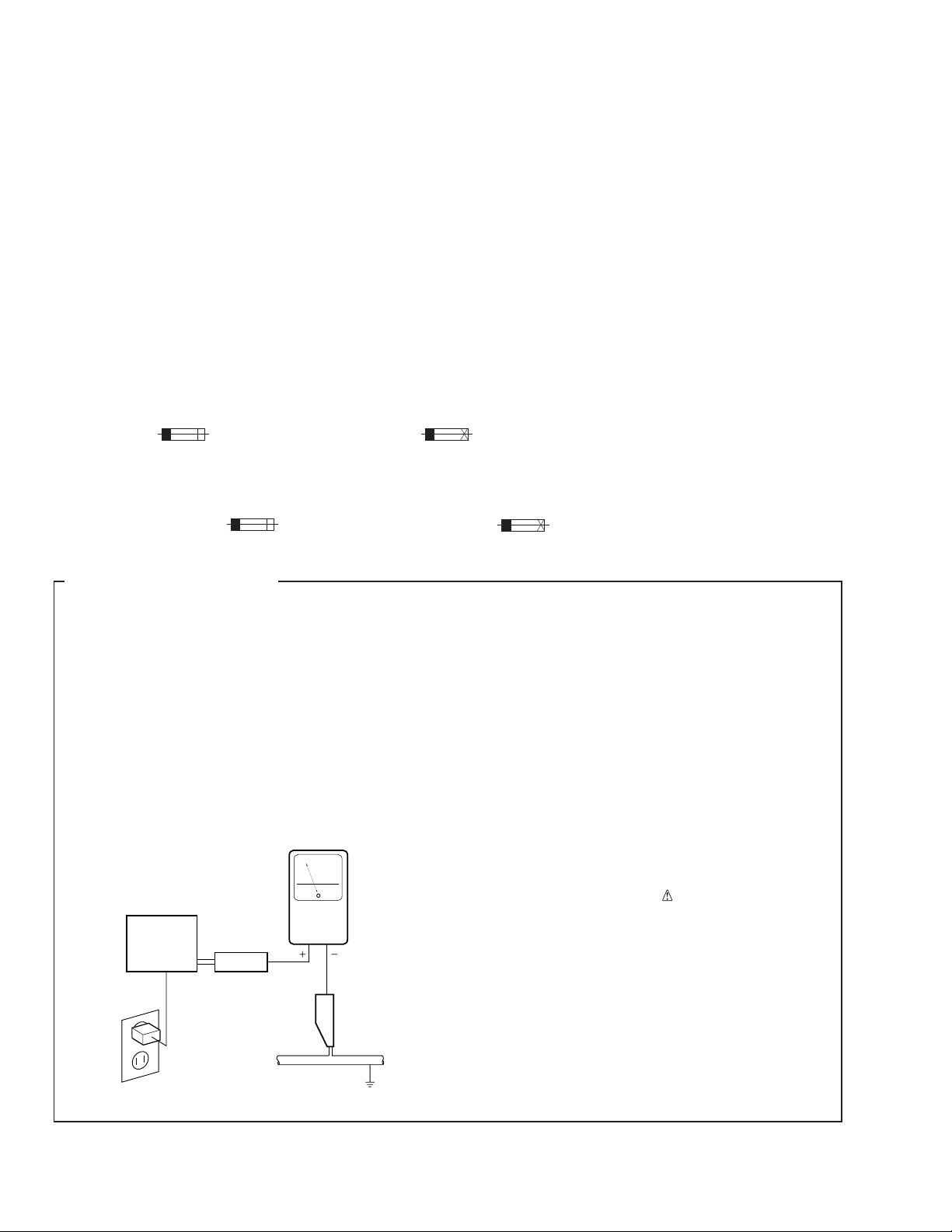
1. SAFETY PRECAUTIONS
The following check should be performed for the
continued protection of the customer and service
technician.
LEAKAGE CURRENT CHECK
Measure leakage current to a known earth ground
(water pipe, conduit, etc.) by connecting a leakage
current tester such as Simpson Model 229-2 or
equivalent between the earth ground and all exposed
metal parts of the appliance (input/output terminals,
screwheads, metal overlays, control shaft, etc.). Plug
the AC line cord of the appliance directly into a 120V
AC 60 Hz outlet and turn the AC power switch on. Any
current measured must not exceed 0.5 mA.
Reading should
not be above
0.5 mA
Earth
ground
Device
under
test
Also test with
plug reversed
(Using AC adapter
plug as required)
Test all
exposed metal
surfaces
AC Leakage Test
Leakage
current
tester
ANY MEASUREMENTS NOT WITHIN THE
LIMITS OUTLINED ABOVE ARE INDICATIVE
OF A POTENTIAL SHOCK HAZARD AND
MUST BE CORRECTED BEFORE RETURNING THE APPLIANCE TO THE CUSTOMER.
2. PRODUCT SAFETY NOTICE
Many electrical and mechanical parts in the appliance
have special safety related characteristics. These are
often not evident from visual inspection nor the
protection afforded by them necessarily can be obtained
by using replacement components rated for voltage,
wattage, etc. Replacement parts which have these
special safety characteristics are identified in this
Service Manual.
Electrical components having such features are
identified by marking with a
on the parts list in this Service Manual.
The use of a substitute replacement component which
does not have the same safety characteristics as the
PIONEER recommended replacement one, shown in the
parts list in this Service Manual, may create shock, fire,
or other hazards.
Product Safety is continuously under review and new
instructions are issued from time to time. For the latest
information, always consult the current PIONEER
Service Manual. A subscription to, or additional copies
of, PIONEER Service Manual may be obtained at a
nominal charge from PIONEER.
on the schematics and
2
2. EXPLODED VIEWS AND PARTS LIST
NOTES:• Parts marked by "NSP" are generally unavailable because they are not in our Master Spare Parts List.
The mark found on some component parts indicates the importance of the safety factor of the part.
•
Therefore, when replacing, be sure to use parts of identical designation.
Screws adjacent to mark on the product are used for disassembly.
•
DV-K101
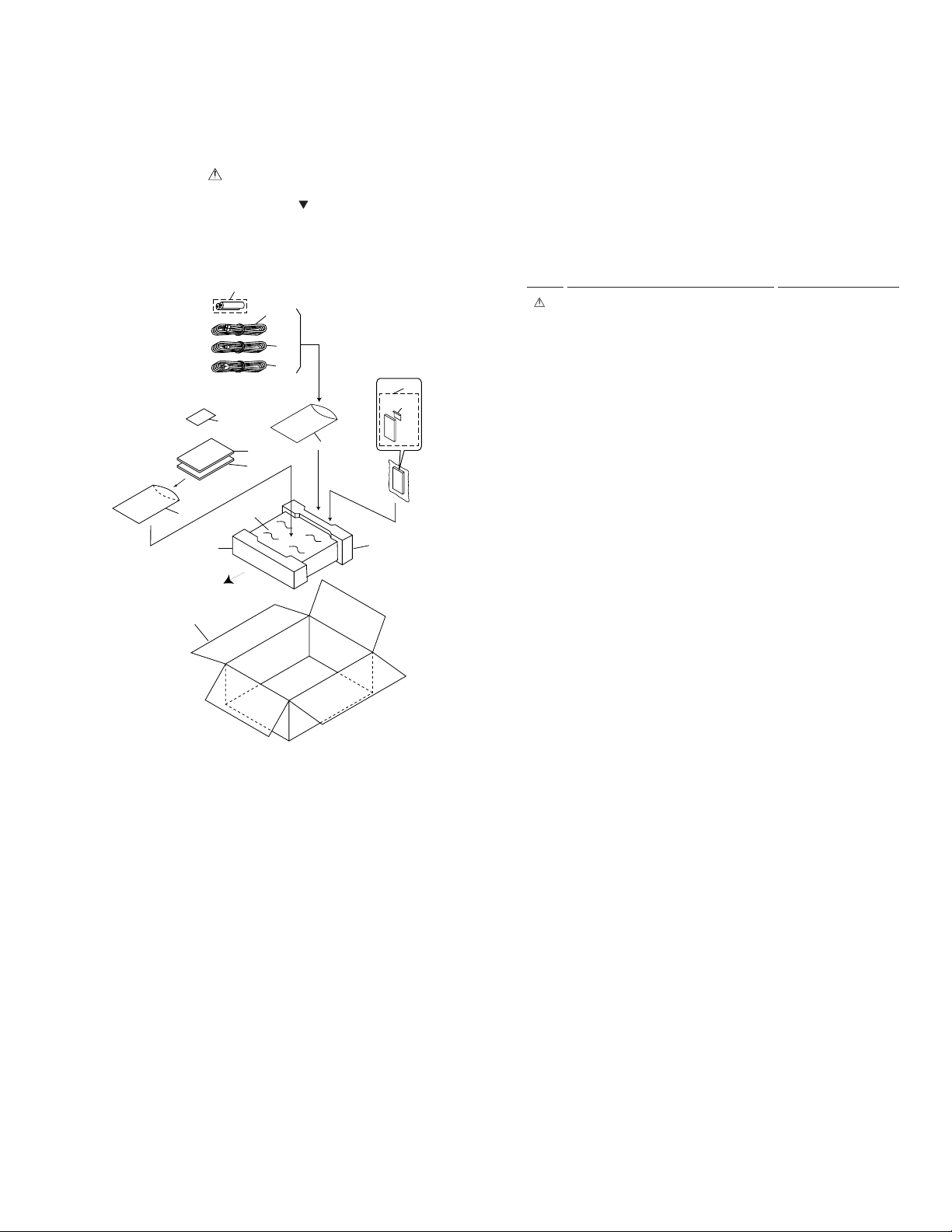
2.1 PACKING
7
8
11
FRONT
14
PACKING PARTS LIST
•
4
3
2
1
9
10
5
6
13
8
12
Mark No. Description Part No.
1 Power Cord ADG1126
2 Video Cord (L=1.5m) VDE1048
3 Audio Cord (L=1.5m) VDE1033
NSP 4 Dry Cell Battery (R6P, AA) VEM-013
5 Operating Instructions VRB1196
(English)
6 Operating Instructions VRC1069
(Simp-chinese)
NSP 7 Warranty Card ARY7020
8 Polyethylene Bag Z21-038
9 Remote Control Unit VXX2576
(CU-DV020)
10 Battery Cover VNK3703
11 Pad F VHA1220
12 Pad R VHA1221
13 Mirror Mat Sheet Z23-007
14 Packing Case VHG1762
3
DV-K101
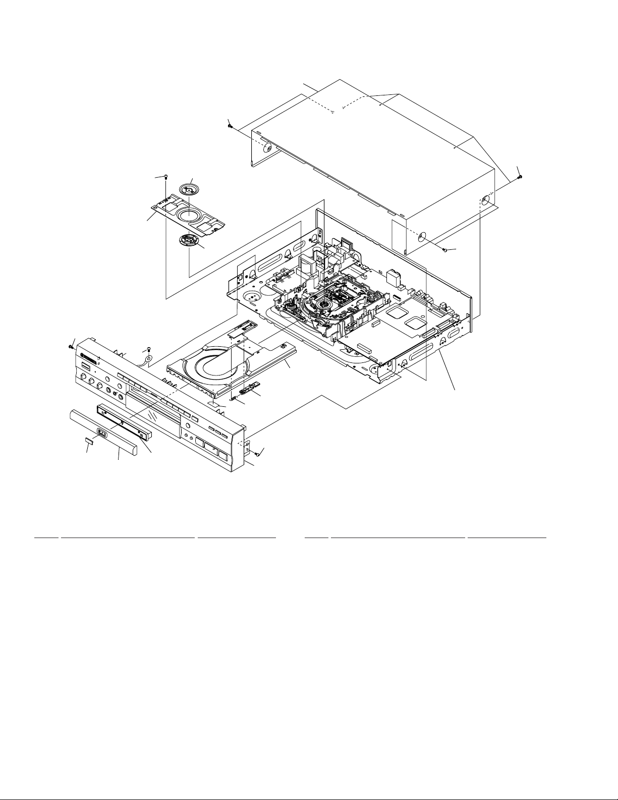
2.2 EXTERIOR SECTION
14
8
1
16
17
9
10
15
17
13
2
EXTERIOR SECTION PARTS LIST
•
3
4
Mark No. Description Part No.
1 Bonnet Case S VXX2581
2 DVD Plate VAM1080
3 Tray Panel Plate VNK4273
4 Tray Panel VNK4158
5 Tray VNL1731
5
12
11
15
Refer to "2.3 FRONT PANEL SECTION"
Mark No. Description Part No.
11 Tray Stopper Spring VBH1277
12 Tray Stopper VNL1739
13 Tray Label VRW1628
14 Screw BPZ26P080FZK
15 Screw IBZ30P080FMC
16
Refer to
"2.4 BOTTOM VIEW SECTION"
6 • • • • •
7 • • • • •
8 Bridge VNE2069
9 Clamper Plate VNE2068
10 Clamper VNL1738
16 Screw BCZ40P060FNI
17 Screw BBZ30P080FMC
4
DV-K101
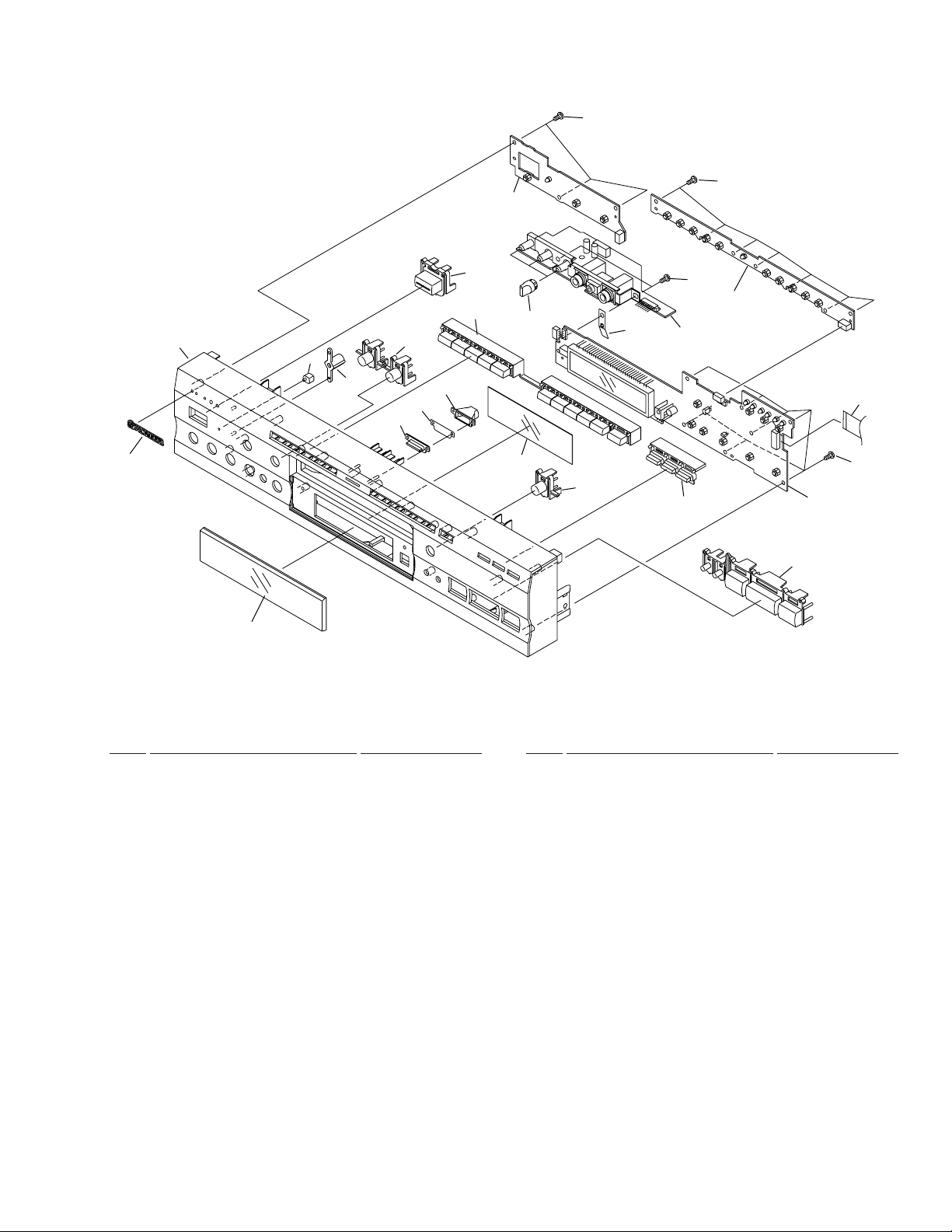
2.3 FRONT PANEL SECTION
4
7
6
19(1/2)
23
12
13
14
22
9
16
16
2
16
3
18
11
19(2/2)
21
20
10
15
16
1
8
5
FRONT PANEL SECTION PARTS LIST
•
Mark No. Description Part No.
NSP 2 PWSB Assy VWG1962
1 FLKY Assy VWG1957
3 KYLB Assy VWG1961
4 Front Panel VNK4255
5 FL Lens VNK4272
6 Name Plate VAM1067
7 LED Lens PNW2019
8 Main Key VNK4269
9 11 Key VNK4271
10 MICB Assy VWV1629
Mark No. Description Part No.
11 FL Filter VEC1643
12 Illumination Lens VNK4264
13 Illumination Filter VEC1983
14 Illumination Holder VNK4265
15 Flexible Cable (14P) VDA1646
(FLKY CN101 – DVDM CN105)
16 Screw BBZ30P080FMC
17 • • • • •
18 Volume Knob VNK4279
19 3 Key VNK4270
20 Light Key VNK4261
21 Earth Plate VBK1075
22 Power Button VNK4059
23 Lens Holder VNK4266
5
DV-K101
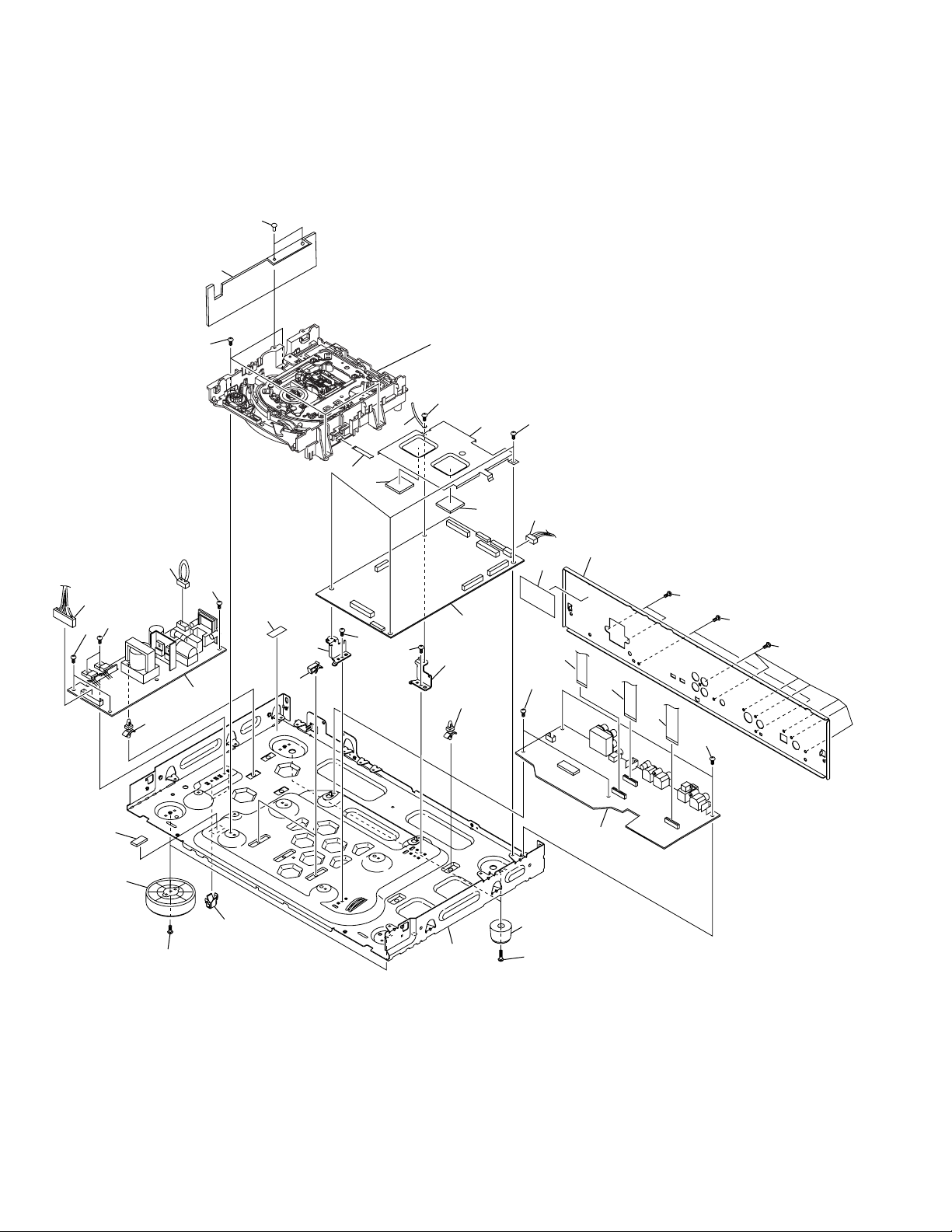
2.4 BOTTOM VIEW SECTION
33
30
25
Refer to
4
"2.5 LOADING MECHANISM ASSY"
23
6
7
8
5
23
23
11
27
14
17
12
32
23
8
23
35
10
13
1
15
23
23
2
10
9
16
18
23
24
22
34
26
21
23
23
23
19
20
23
3
6

BOTTOM VIEW SECTION PARTS LIST
•
Mark No. Description Part No.
1 POWER SUPPLY Assy VWR1284
NSP 4 Loading Mechanism Assy VWT1147
NSP 6 Cord Stopper ZCB-069Z
NSP 9 Card Spacer DEC1770
NSP 10 PCB Holder VNE2122
NSP 12 PCB Holder PNW2100
NSP 16 Chassis VNA1954
2 DVDM Assy VWS1345
3 KRJB Assy VWV1611
5 Heat Sink VNE2134
7 Flexible Cable (12P) VDA1648
(LOSB CN301 – DVDM CN107)
8 Radiation Seat VEB1285
11 Housing Assy (14P) VKP2161
(POWER SUPPLY CN201 – DVDM CN101)
13 Clamp DEC2007
14 Screw BCZ30P080FZK
15 Guard VNK4100
17 Insulator PNW2766
DV-K101
Mark No. Description Part No.
18 Insulator Assy VXA1680
19 Flexible Cable (14P) VDA1646
(KRJB CN191 – DVDM CN803)
20 Flexible Cable (17P) VDA1650
(KRJB CN901 – DVDM CN802)
21 Rear Panel VNA2012
22 Housing Assy (4P) VKP2191
(DVDM CN801 – KRJB CN301)
23 Screw BBZ30P080FMC
24 Screw BBZ30P180FMC
25 Screw BBZ30P100FMC
26 Flexible Cable (9P) VDA1687
(KRJB CN101 – MICB CN402)
NSP 27 Filter Cushion VEC1287
28 • • • • •
29 • • • • •
30 Sheet VEC2000
31 • • • • •
NSP 32 Housing Assy VKP2189
33 Nylon Rivet AEC-525
NSP 34 Fuse Caution Label (G) VRW-548
35 Fuse Caution Label VRW1693
7
DV-K101
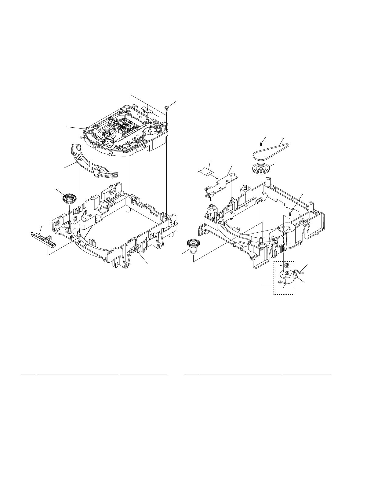
2.5 LOADING MECHANISM ASSY
• Top View • Bottom View
Refer to
"2.6 SERVO MECHANISM
ASSY"
5
1
3
4
20
6
2
18
10
17
9
13
7
8
16
15
LOADING MECHANISM ASSY PARTS LIST
•
Mark No. Description Part No.
1 Servo Mechanism Assy-S VXX2538
2 Screw DBA1006
3 Drive Cam VNL1736
4 Drive Gear VNL1735
5 Lock Plate VNL1820
6 Loading Base VNL1730
7 Rubber Belt VEB1260
NSP 9 LOSB Assy VWG1885
8 Gear Pulley VNL1733
10 Loading Gear VNL1734
11
12
Mark No. Description Part No.
11 Loading Motor Assy VXX2505
12 DC Motor PXM1027
13 Motor Pulley PNW1634
NSP 14 LOMB Assy VWG1886
15 Connector Assy (2P) VKP2184
(LOMB CN401 – LOSB CN303)
16 Screw VBA1055
17 Screw Z39-019
18 Flexible Cable (8P) VDA1649
(LOSB CN302 – INSB CN202)
19 • • • • •
20 Stopper DNH2076
14
8
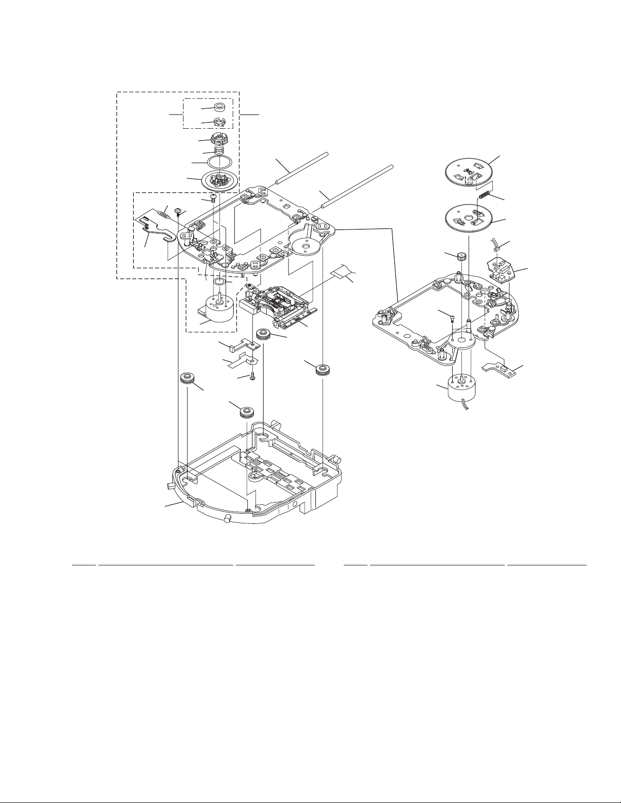
2.6 SERVO MECHANISM ASSY
• Top View • Bottom View
DV-K101
13
14
29
3
4
5
6
7
9
30
8
15
16
26
18
18
2
32
1
10
11
12
23
27
9
17
18
18
24
20
21
22
28
25
31
19
SERVO MECHANISM ASSY PARTS LIST
•
Mark No. Description Part No.
1 Spindle Motor Assy VXX2563
NSP 3 Magnet VYM1024
NSP 4 Magnet Holder VNE2070
NSP 7 Disc Table VNL1747
NSP 8 Motor VXM1071
2 Magnet Holder Assy VXX2507
5 Centering Ring VNL1746
6 Centering Spring VBH1278
9 Screw JGZ17P028FMC
10 Sub Guide Bar VLL1489
11 Guide Bar VLL1488
12 Mechanism Base VNL1748
13 Hook VNL1770
14 Hook Spring VBH1291
15 Slider VNL1745
16 Hold Spring VNC1011
17 Pickup Assy VWY1046
Mark No. Description Part No.
18 Floating Rubber DEB1315
19 Float Base VNL1732
20 Gear D VNL1766
21 Gear Spring VBH1306
22 Gear E VNL1767
23 Gear F VNL1768
24 Motor VXM1062
NSP 25 INSB Assy VWG1883
26 Screw PBZ20P050FMC
27 Flexible Cable (20P) VDA1680
(DVDM CN102 – Pickup Assy)
28 Connector Assy (3P) VKP2150
(INSB CN201 – FGSB CN101)
NSP 29 Table Sheet DEC2040
30 Screw PBA1048
NSP 31 FGSB Assy VWG1884
NSP 32 Sheet VEC1959
9
1
23
DV-K101
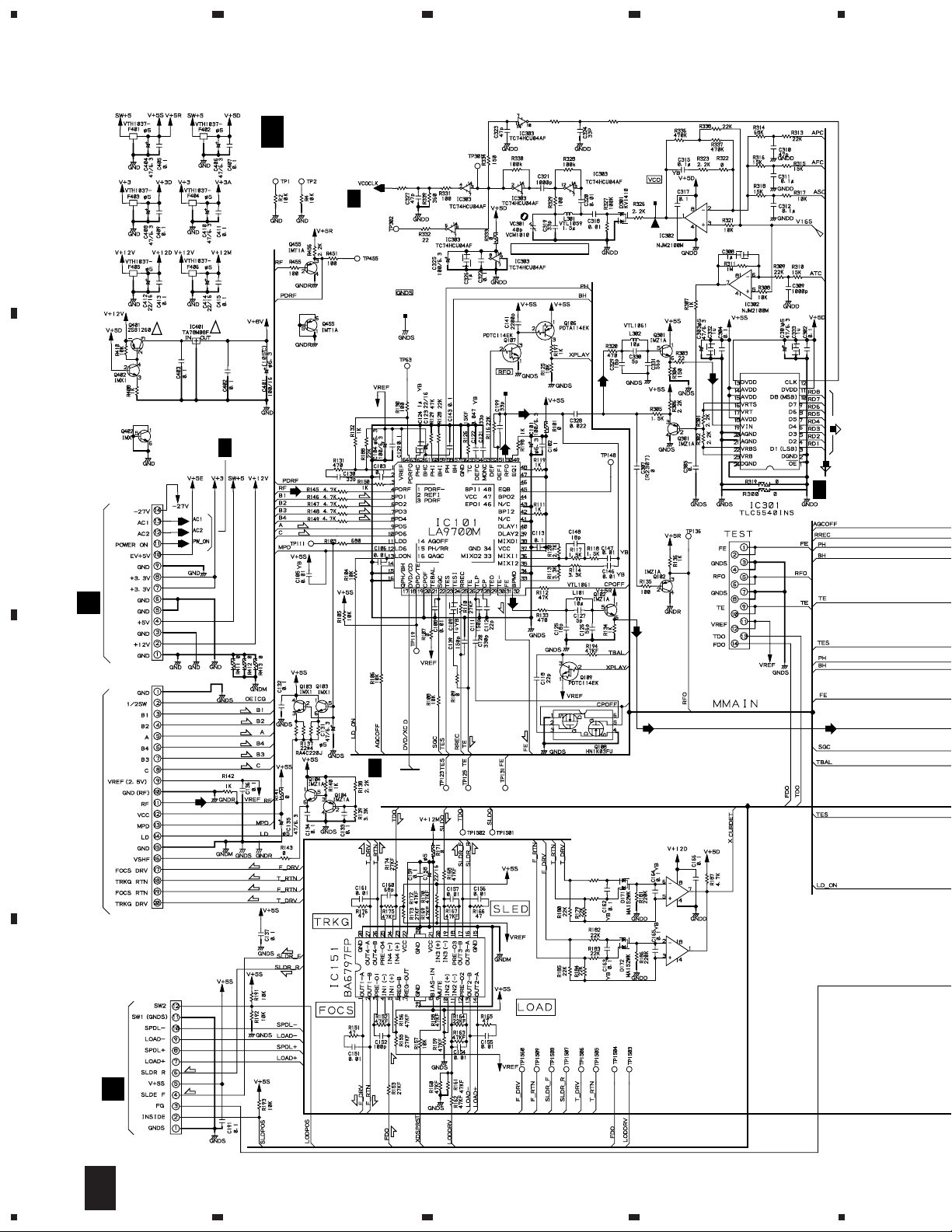
3. SCHEMATIC DIAGRAM
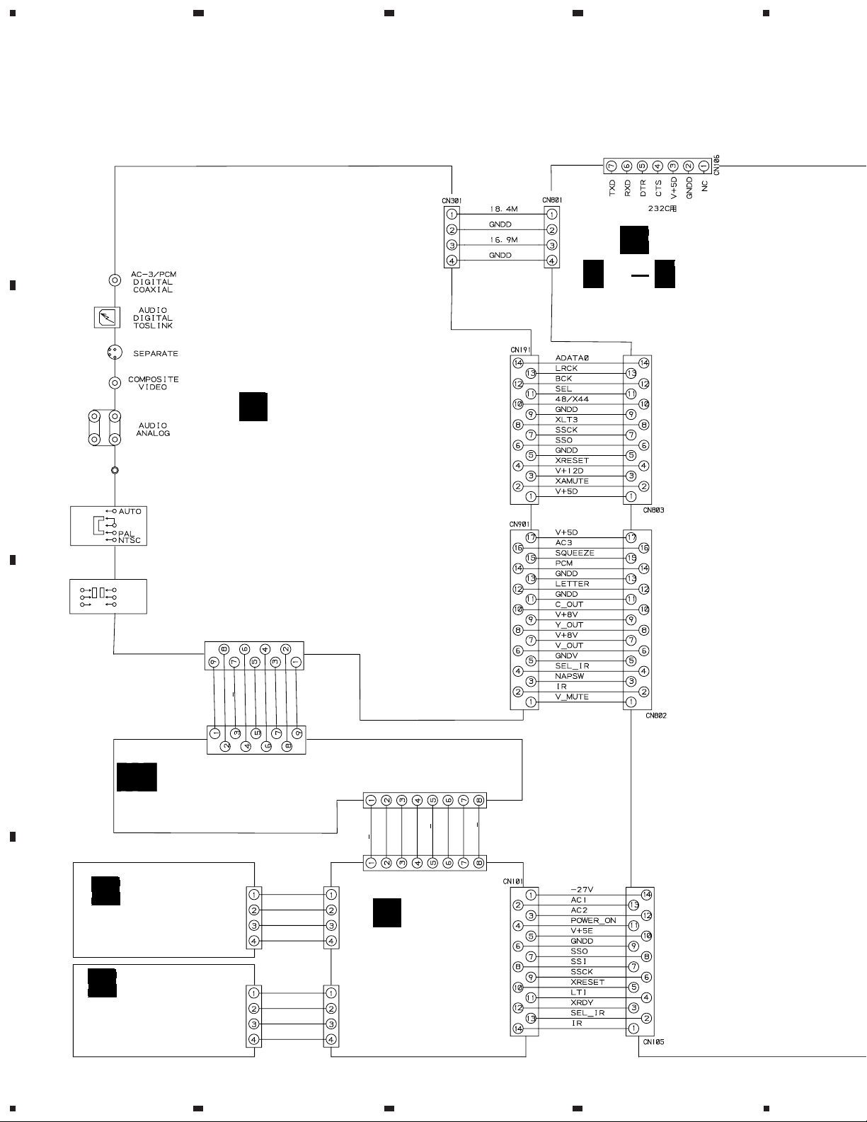
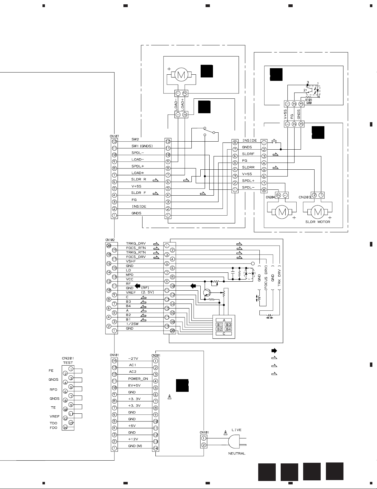
3.1 OVERALL CONNECTION DIAGRAM, LOMB, LOSB, INSB
and FGSB ASSEMBLIES
A
4
H
()
1/3 3/3
H H
DVDM ASSY
(VWS1345)
B
I
KRJB ASSY
(VWV1611)
SR IN
PAL / NTSC
PAL / NTSC
SW
SW
ON
ATTENUATOR
SW
OFF
CN101
C
CN402
GA
MICB ASSY
(VWV1629)
SI
XCS
–8V
SCK0
GNDD
XMIC ON
MIC
+8V
GNDA
CN401
XCS
SI
G
KYLB ASSY
(VWG1961)
CN201
V+5D
LAMP
GND
KEY1
MIC CONT
CN102
FLKY ASSY
SCK0
E
XMIC ON
GNDD
V+5V
ECHO VR
CN104
(VWG1957)
D
F
PWSB ASSY
(VWG1962)
10
1234
CN301
V+5V
LED
GND
KEY0
CN103
5
678
DV-K101
Note : When ordering service parts, be sure to refer to "EXPLODED VIEWS and P AR TS LIST" or "PCB PARTS LIST".
LOAB ASSY (VWM1798)
LOADING MOTOR
ASSY :VXX2505
CN401
B2B-PH-K-S
CN303
B2B-PH-K-S
CN301
VKN1272
(S) (S)
(S)
A
LOMB ASSY
(VWG1886)
B
LOSB ASSY
(VWG1885)
S301
(S)
VKN1268
CN302
SMEB ASSY (VWM1797)
FGSB ASSY
D
(VWG1884)
PC101
GP2S27(B)
CN101
B3B-PH-K-S
CN201
B3B-PH-K-S
CN202
VKN1239
S201
(S)
(S)
C
INSB ASSY
(VWG1883)
A
B
SPINDLE MOTOR
ASSY : VXX2563 VXM1062
(T)
(F)
(T)
(F)
(T)
(F)
(F)
(T)
(F)
(F)
(T)
(F)
(T)
(F)
PICKUP ASSY
(VWY1046)
: RF SIGNAL ROUTE
(F)
: FOCUS SERVO LOOP LINE
(T)
: TRACKING SERVO LOOP LINE
(S)
: SLIDER SERVO LOOP LINE
C
J
POWER
SUPPLY
ASSY
(VWR1284)
AC 120V
50/60Hz
AC POWER CORD
ADG1126
D
5
6
7
BA
C
D
8
11
1
23
DV-K101
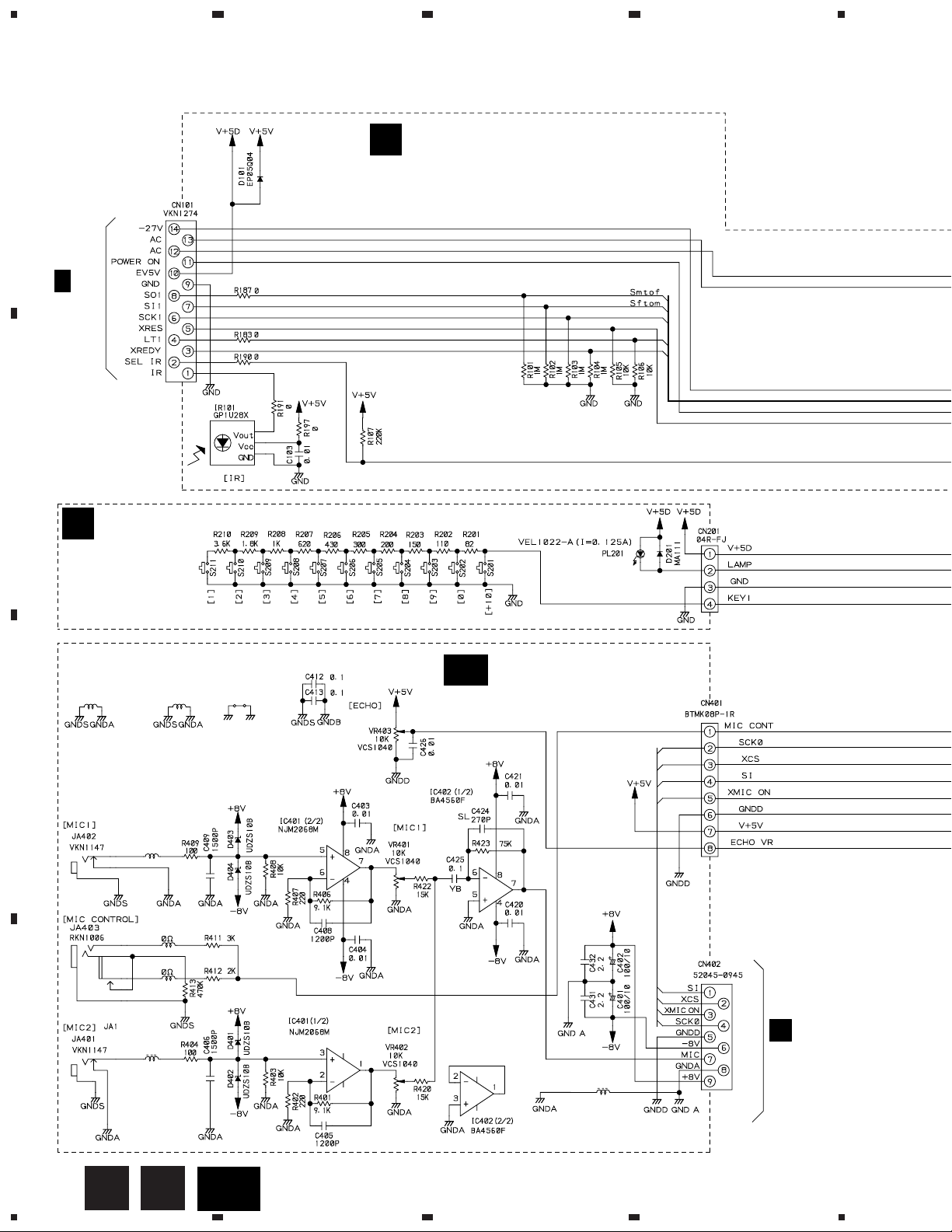
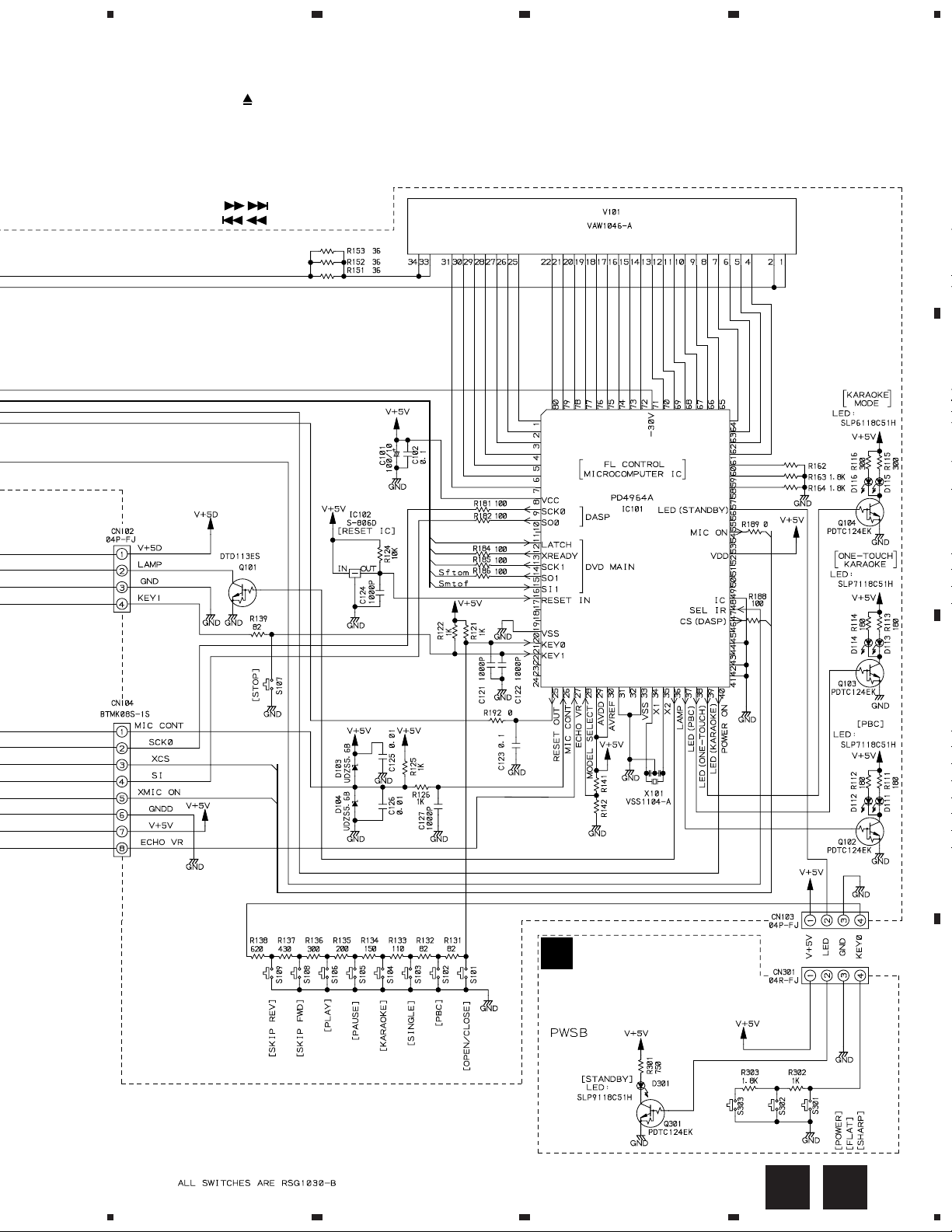
3.2 FLKY, PWSB, KYLB and MICB ASSEMBLIES
E
A
H
2/3
CN105
B
FLKY ASSY
(VWG1957)
4
G
[Lamp]
KYLB ASSY
(VWG1961 )
F405
DTF1069
C
F402
DTF1066
R803
R804
F406
DTF1069
GNDB
J401
CHASSIS
GND
GA
MICB ASSY
(VWV1629)
( )
D
12
E
F401
DTF1066
F410
DTF1067
G
1234
GA
( )
I
CN101
5
678
DV-K101
FLKY ASSY
S101 :OPEN/CLOSE ( )
S102 : PLAYBACK CONTROL
S103 : ONE-TOUCH KARAOKE
S104 : KARAOKE MODE
S105 : PAUSE (8)
S106 : PLAY(3)
S107 : STOP(7)
S108 : SKIP FWD ( )
S109 : SKIP REV ( )
KYLB ASSY
S201 : +10
S202 : 0
S203 : 9
S204 : 8
S205 : 7
S206 : 6
S207 : 5
S208 : 4
S209 : 3
S210 : 2
S211 : 1
PWSB ASSY
S301 : KEY CONTROL HIGH (#)
S302 : KEY CONTROL LOW (I)
S303 : POWER STANDBY/ON
FL TUBE
0
A
ORANGE
B
F
PWSB ASSY
(VWG1962)
16K 2.7K
GREEN
GREEN
C
5MHz
D
RED
FE
5
6
7
8
13
1
DV-K101
23
4
3.3 DVDM ASSY(1/3)
A
!
B
S14B-PH-SM3
CN101
VTL1074
L342
H
DVDM ASSY(1/3)
1/3
VTL1074
L335
(5/6)
(VWS1345)
VTL1074
L340
H
2/3
VKF1001
TP400
!
H
2/3
(F)
(F)
(F)
(T)
(T)
(F)
(2/6)
(3/6)
(1/6)
VCO Offset ADJ.
VKF1001
TP100
(4/6)
(6/6)
VKF1001
TP300
1/2
2/2
(ROM)
(ROM)
H
2/3
CN201
J
(F)
(F)
(T)
(F)
(F)
C
PICKUP ASSY
CN102
VKN1445
VKN1416
CN107
(T)
(F)
(T)
(F)
(T)
(S)
(S)
H
3/3
(T)
(T)
(T)
(S)
(F)
CN201
VKN1324
(F)
(T)
(S)
(S)
R177
33k
R178
33k
2/2
IC171
BA10393F
1/2
IC171
BA10393F
D
CN301
B
14
H
1/3
(S)
(S)
(F)
(F)
(F)
(F)
1234
IC506
TC74VHCT245AFT
AGCOFF
VKF1001
TP200
5
678
DV-K101
(F)
: FOCUS SERVO LOOP LINE
(T)
: TRACKING SERVO LOOP LINE
(S)
: SLIDER SERVO LOOP LINE
SRM2B256SLMX70
A
H
2/3
B
IC501
PD4889A
: RF SIGNAL ROUTE
(ROM)
: ROM DATA SIGNAL ROUTE
IC504
TC74VHC20FT
IC505(1/2)
TC74VHC139FT
IC505(2/2)
H
3/3
TC74VHC139FT
(T)
(F)
LD-ON
H
2/3
XRESET,DOUT,SBSY,
PW,SFSY,SBCK,LRSY,
ROMCK,ROMXA,MON,
(ROM)
(T)
(T)
(F)
(F)
IC201
C2F,FG
LC78650NE
(S)
(F)
(S)
(F)
(T)(T)
C271 4700p
R277
100k
2/2
R271 150k
33k
R275
150k
R276
R273 220k
H
2/3
C
1/2
LEVEL SHIFT
5
6
7
H
2/3
H
1/3
15
8
D
1
DV-K101
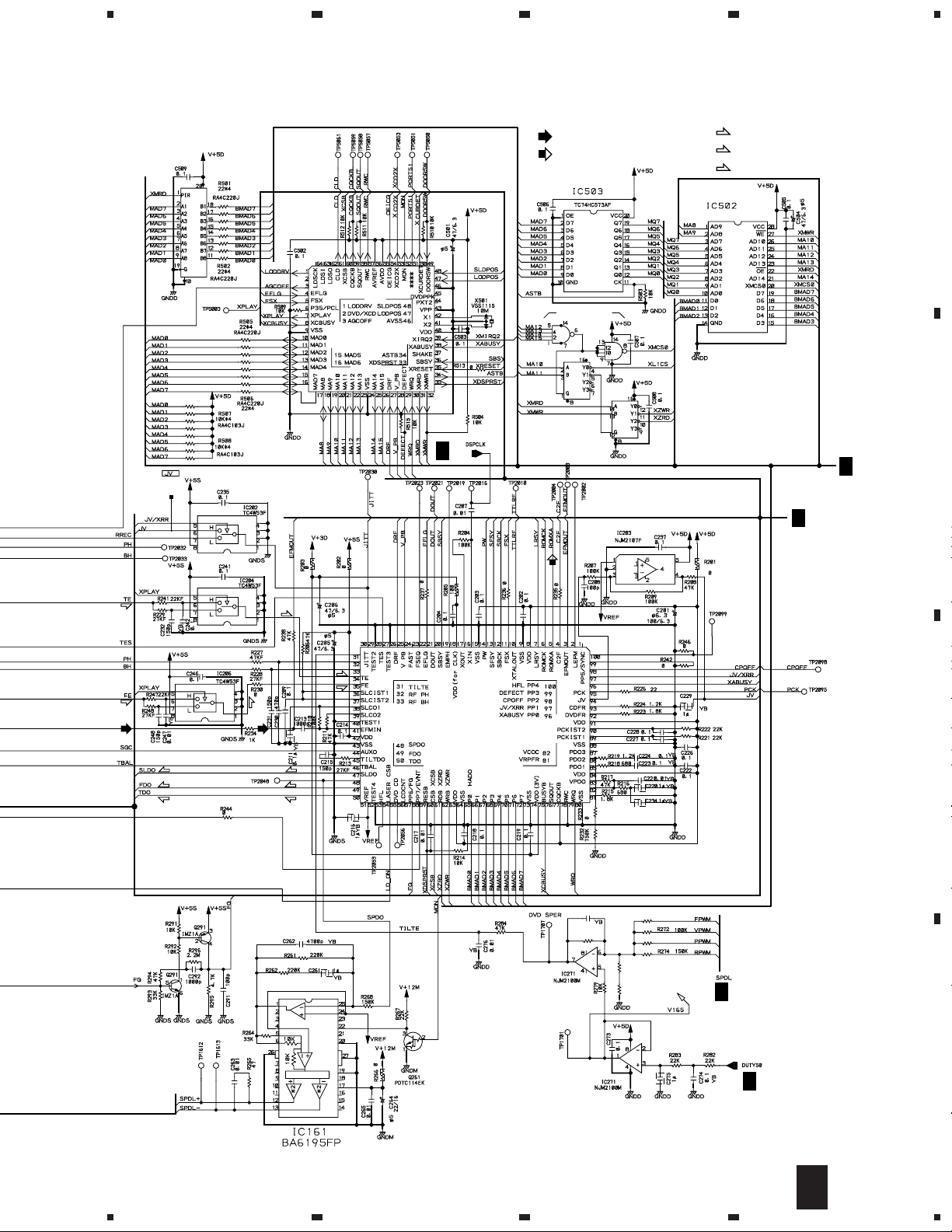
3.4 DVDM ASSY(2/3)
23
4
A
4M
VYW1550
B
H
DVDM ASSY(2/3)
2/3
(VWS1345)
H
1/3
C2F,XRESET
H
3/3
XCSDOLV,DOLV-CD,XWRL,XWRH,
XRD,XLT3,XAMUTE,XDREQ1,
HCPUCK,IR,SEL-IR,XDVRST1,
XAVIRQ0,48/X44,HIBSEL,XCS6,
XDACK1,NAP SW
CN106
VKN1411
H
A2-A10
DATA
H
H
1/3
3/3
3/3
ADDRESS
C
IC605(1/2)
TC74VHC139FT
D
IC605(2/2)
TC74VHC139FT
X602
VSS1114
20MHz
Q771,Q772:
PDTC114TK
16
H
2/3
1234
 Loading...