

Pioneer DVJX-1 Owners manual
DVD PLAYER
DVJ-X1
Operating Instructions
CAUTION
RISK OF ELECTRIC SHOCK
DO NOT OPEN
The lightning flash with arrowhead symbol,
within an equilateral triangle, is intended to
alert the user to the presence of uninsulated
"dangerous voltage" within the product's
enclosure that may be of sufficient
magnitude to constitute a risk of electric
shock to persons.
CAUTION:
TO PREVENT THE RISK OF ELECTRIC
SHOCK, DO NOT REMOVE COVER (OR
BACK). NO USER-SERVICEABLE PARTS
INSIDE. REFER SERVICING TO QUALIFIED
SERVICE PERSONNEL.
The exclamation point within an equilateral
triangle is intended to alert the user to the
presence of important operating and
maintenance (servicing) instructions in the
literature accompanying the appliance.
D1-4-2-3_En-A
NOTE: THE NO USER-SERVICEABLE PARTS COMPARTMENT WARNING IS LOCATED ON THE APPLIANCE BOTTOM.
WARNING:
prevent fire or shocks hazard, do not expose this
apparatus to rain or moisture and do not put any
water source near this apparatus, such as vase,
flower pot, cosmetics container and medicine
bottle etc.
When using this product follow the instructions
written on the underside of the unit, which
concern rated voltage, etc.
WARNING: Handling the cord on this product or
cords associated with accessories sold with the
product will expose you to lead, a chemical known to
the State of California and other governmental
entities to cause cancer and birth defects or other
reproductive harm.
Wash hands after handling
The apparatus is not waterproofs, to
D3-4-2-1-3_En
D3-4-2-2-4_En
D36-P4_En
CAUTION – PREVENT ELECTRIC SHOCK DO
NOT USE THIS (POLARIZED) PLUG
WITH AN EXTENSION CORD.
RECEPTACLE OR OTHER OUTLET
UNLESS THE BLADES CAN BE
FULLY INSERTED TO PREVENT
BLADE EXPOSURE.
ATTENTION –
POUR PREVENIR LES CHOCS
ELECTRIQUES NE PAS UTILISER
CETTE FICHE POLARISEE AVEC UN
PROLONGATEUR UNE PRISE DE
COURANT OU UNE AUTRE SORTIE
DE COURANT, SAUF SI LES LAMES
PEUVENT ETRE INSEREES A FOND
SANS EN LAISSER AUCUNE PARTIE
A DECOUVVERT.
D2-4-4-1_EF
IMPORTANT NOTICE – THE SERIAL NUMBER FOR THIS EQUIPMENT IS LOCATED IN THE BOTTOM.
PLEASE WRITE THIS SERIAL NUMBER ON YOUR ENCLOSED WARRANTY CARD AND
KEEP IN A SECURE AREA. THIS IS FOR YOUR SECURITY.
D1-4-2-6-1_EnA
NOTE: This equipment has been tested and found to comply with the limits for a Class B digital device, pursuant to
Part 15 of the FCC Rules. These limits are designed to provide reasonable protection against harmful interference in
a residential installation. This equipment generates, uses, and can radiate radio frequency energy and, if not
installed and used in accordance with the instructions, may cause harmful interference to radio communications.
However, there is no guarantee that interference will not occur in a particular installation. If this equipment does
cause harmful interference to radio or television reception, which can be determined by turning the equipment off
and on, the user is encouraged to try to correct the interference by one or more of the following measures:
– Reorient or relocate the receiving antenna.
– Increase the separation between the equipment and receiver.
– Connect the equipment into an outlet on a circuit different from that to which the receiver is connected.
– Consult the dealer or an experienced radio/TV technician for help.
D8-10-1-2_En
Information to User
Alteration or modifications carried out without appropriate authorization may invalidate the user’s right to operate
the equipment.
D8-10-2_En
CAUTION: This product satisfies FCC regulations when shielded cables and connectors are used to connect the
unit to other equipment. To prevent electromagnetic interference with electric appliances such as radios and
televisions, use shielded cables and connectors for connections.
D8-10-3a_En
This Class B digital apparatus complies with Canadian ICES-003.
Cet appareil numérique de la Classe B est conforme à la norme NMB-003 du Canada.
2
D8-10-1-3_EF
CAUTION : USE OF CONTROLS OR ADJUSTMENTS OR PERFORMANCE OF PROCEDURES OTHER THAN THOSE
SPECIFIED HEREIN MAY RESULT IN HAZARDOUS RADIATION EXPOSURE.
CAUTION : THE USE OF OPTICAL INSTRUMENTS WITH THIS PRODUCT WILL INCREASE EYE HAZARD.
IMPORTANT SAFETY INSTRUCTIONS
READ INSTRUCTIONS — All the safety and
operating instructions should be read before the
product is operated.
RETAIN INSTRUCTIONS — The safety and
operating instructions should be retained for
future reference.
HEED WARNINGS — All warnings on the product
and in the operating instructions should be
adhered to.
FOLLOW INSTRUCTIONS — All operating and use
instructions should be followed.
CLEANING — The product should be cleaned only
with a polishing cloth or a soft dry cloth. Never
clean with furniture wax, benzine, insecticides
or other volatile liquids since they may corrode
the cabinet.
ATTACHMENTS — Do not use attachments not
recommended by the product manufacturer as
they may cause hazards.
WATER AND MOISTURE — Do not use this
product near water — for example, near a
bathtub, wash bowl, kitchen sink, or laundry
tub; in a wet basement; or near a swimming
pool; and the like.
ACCESSORIES — Do not place this product on an
unstable cart, stand, tripod, bracket, or table.
The product may fall, causing serious injury to a
child or adult, and serious damage to the
product. Use only with a cart, stand, tripod,
bracket, or table recommended by the
manufacturer, or sold with the product. Any
mounting of the product should follow the
manufacturer’s instructions, and should use a
mounting accessory recommended by the
manufacturer.
CART — A product and cart combination should be
moved with care. Quick stops, excessive force,
and uneven surfaces may cause the product
and cart combination to overturn.
VENTILATION — Slots and openings in the cabinet
are provided for ventilation and to ensure
reliable operation of the product and to protect
it from overheating, and these openings must
not be blocked or covered. The openings should
never be blocked by placing the product on a
bed, sofa, rug, or other similar surface. This
product should not be placed in a built-in
installation such as a bookcase or rack unless
proper ventilation is provided or the
manufacturer’s instructions have been adhered
to.
POWER SOURCES — This product should be
operated only from the type of power source
indicated on the marking label. If you are not
sure of the type of power supply to your home,
consult your product dealer or local power
company.
LOCATION – The appliance should be installed in a
stable location.
NONUSE PERIODS – The power cord of the
appliance should be unplugged from the outlet
when left un-used for a long period of time.
GROUNDING OR POLARIZATION
• If this product is equipped with a polarized
alternating current line plug (a plug having one
blade wider than the other), it will fit into the
outlet only one way. This is a safety feature. If
you are unable to insert the plug fully into the
outlet, try reversing the plug. If the plug should
still fail to fit, contact your electrician to replace
your obsolete outlet. Do not defeat the safety
purpose of the polarized plug.
• If this product is equipped with a three-wire
grounding type plug, a plug having a third
(grounding) pin, it will only fit into a grounding
type power outlet. This is a safety feature. If you
are unable to insert the plug into the outlet,
contact your electrician to replace your obsolete
outlet. Do not defeat the safety purpose of the
grounding type plug.
POWER-CORD PROTECTION — Power-supply
cords should be routed so that they are not likely
to be walked on or pinched by items placed
upon or against them, paying particular
attention to cords at plugs, convenience
receptacles, and the point where they exit from
the product.
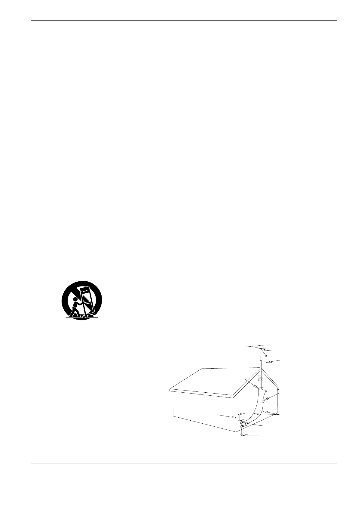
OUTDOOR ANTENNA GROUNDING — If an
outside antenna or cable system is connected to
the product, be sure the antenna or cable
system is grounded so as to provide some
protection against voltage surges and built-up
static charges. Article 810 of the National
Electrical Code, ANSI/NFPA 70, provides
information with regard to proper grounding of
the mast and supporting structure, grounding of
the lead-in wire to an antenna discharge unit,
size of grounding conductors, location of
antenna-discharge unit, connection to
grounding electrodes, and requirements for the
grounding electrode. See Figure A.
LIGHTNING — For added protection for this
product during a lightning storm, or when it is
left unattended and unused for long periods of
time, unplug it from the wall outlet and
disconnect the antenna or cable system. This
will prevent damage to the product due to
lightning and power-line surges.
POWER LINES — An outside antenna system
should not be located in the vicinity of overhead
power lines or other electric light or power
circuits, or where it can fall into such power
lines or circuits. When installing an outside
antenna system, extreme care should be taken
to keep from touching such power lines or
circuits as contact with them might be fatal.
OVERLOADING — Do not overload wall outlets,
extension cords, or integral convenience
receptacles as this can result in a risk of fire or
electric shock.
ELECTRIC
SERVICE
EQUIPMENT
Fig. A
OBJECT AND LIQUID ENTRY — Never push
objects of any kind into this product through
openings as they may touch dangerous voltage
points or short-out parts that could result in a
fire or electric shock. Never spill liquid of any
kind on the product.
SERVICING — Do not attempt to service this
product yourself as opening or removing covers
may expose you to dangerous voltage or other
hazards. Refer all servicing to qualified service
personnel.
DAMAGE REQUIRING SERVICE — Unplug this
product from the wall outlet and refer servicing
to qualified service personnel under the
following conditions:
• When the power-supply cord or plug is
damaged.
• If liquid has been spilled, or objects have fallen
into the product.
• If the product has been exposed to rain or water.
• If the product does not operate normally by
following the operating instructions. Adjust only
those controls that are covered by the operating
instructions as an improper adjustment of other
controls may result in damage and will often
require extensive work by a qualified technician
to restore the product to its normal operation.
• If the product has been dropped or damaged in
any way.
• When the product exhibits a distinct change in
performance — this indicates a need for service.
REPLACEMENT PARTS — When replacement parts
are required, be sure the service technician has
used replacement parts specified by the
manufacturer or have the same characteristics
as the original part. Unauthorized substitutions
may result in fire, electric shock, or other
hazards.
SAFETY CHECK — Upon completion of any service
or repairs to this product, ask the service
technician to perform safety checks to
determine that the product is in proper
operating condition.
WALL OR CEILING MOUNTING — The product
should not be mounted to a wall or ceiling.
HEAT — The product should be situated away from
heat sources such as radiators, heat registers,
stoves, or other products (including amplifiers)
that produce heat.
ANTENNA
LEAD IN
WIRE
GROUND
CLAMP
ANTENNA
DISCHARGE UNIT
(NEC SECTION 810-20)
GROUNDING CONDUCTORS
(NEC SECTION 810-21)
GROUND CLAMPS
POWER SERVICE GROUNDING
ELECTRODE SYSTEM
(NEC ART 250, PART H)
NEC — NATIONAL ELECTRICAL CODE
D6-8-2-1_En
D1-4-2-2_En
3
Before Operating
Thank you for buying this Pioneer product.
Please read through these operating instructions so you will know how to operate your model properly. After you have finished reading
the instructions, put them away in a safe place for future reference.
In some countries or regions, the shape of the power plug and power outlet may sometimes differ from that shown in the explanatory
drawings. However the method of connecting and operating the unit is the same. K015 En
Confirming Accessories
SD memory card ................................................................................... 1
Operating Instructions .......................................................................... 1
Video cable ............................................................................................ 1
Audio cable ...........................................................................................1
Control cord ..........................................................................................1
Power cord ............................................................................................ 1
Forcible eject pin (mounted on unit’s bottom panel)............................. 1
Warranty card ........................................................................................ 1
We Want You Listening For A Lifetime
Used wisely, your new sound equipment will
provide a lifetime of fun and enjoyment. Since
hearing damage from loud noise is often
undetectable until it is too late, this manufacturer
and the Electronic Industries Association’s
Selecting fine audio equipment such as the unit
you’ve just purchased is only the start of your
musical enjoyment. Now it’s time to consider how
you can maximize the fun and excitement your
equipment offers. This manufacturer and the
Electronic Industries Association’s Consumer
Electronics Group want you to get the most out of
your equipment by playing it at a safe level. One that
lets the sound come through loud and clear without
annoying blaring or distortion-and, most importantly,
without affecting your sensitive hearing.
Sound can be deceiving. Over time your hearing
“comfort level” adapts to higher volumes of sound.
So what sounds “normal” can actually be loud and
harmful to your hearing. Guard against this by
setting your equipment at a safe level BEFORE your
hearing adapts.
To establish a safe level:
• Start your volume control at a low setting.
• Slowly increase the sound until you can hear it
comfortably and clearly, and without distortion.
Once you have established a comfortable sound
level:
• Set the dial and leave it there.
Consumer Electronics Group recommend you avoid
prolonged exposure to excessive noise. This list of
sound levels is included for your protection.
Decibel
Level Example
30 Quiet library, soft whispers
40
Living room, refrigerator, bedroom away from traffic
50 Light traffic, normal conversation, quiet office
60 Air conditioner at 20 feet, sewing machine
70 Vacuum cleaner, hair dryer, noisy restaurant
80
Average city traffic, garbage disposals, alarm clock
at two feet.
THE FOLLOWING NOISES CAN BE DANGEROUS
UNDER CONSTANT EXPOSURE
90
Subway, motorcycle, truck traffic, lawn mower
100 Garbage truck, chain saw, pneumatic drill
120 Rock band concert in front of speakers,
thunderclap
140 Gunshot blast, jet plane
180 Rocket launching pad
Information courtesy of the Deafness Research Foundation.
Taking a minute to do this now will help to prevent
hearing damage or loss in the future. After all, we
want you listening for a lifetime.
4
S001_En

Contents
Before Operating
Before Operating
Confirming Accessories ........................................................... 4
Features ................................................................................... 6
Handling Precautions ............................................................... 8
Discs Usable with This Unit ..................................................... 9
Names and Functions of Parts ............................................... 11
Rear panel ........................................................................ 11
Operation panel ................................................................ 12
Display .............................................................................. 14
Jog dial display ................................................................. 15
Playing images from the DVJ-X1 on a television set ........ 15
Connections ........................................................................... 16
1. Connections to DJ mixer (DJM-600, DJM-500, DJM-300,
DJM-909, DJM-707 or DJM-3000)
(audio output and control connector) ........................... 16
2. Control cord connection for relay play ......................... 16
3. Connection to stereo amplifier (without DJ mixer) ...... 17
4. Connection to component equipped
with digital input connector.......................................... 17
5. Connection to television monitor
(composite video/S-Video) ........................................... 18
Connection to television monitor (component video) ...
6.
7. Connection to video mixer ........................................... 19
8. Connecting the power cord ......................................... 19
18
Preparations
Setup ...................................................................................... 20
How to perform setup ...................................................... 20
Using the Setup Navigator ............................................... 20
Setup Menu items ............................................................ 22
To return all settings to their factory defaults ................... 23
Using the Setup Menu ..................................................... 23
Advanced settings ............................................................ 24
Adjusting Dolby Digital audio ............................................ 24
Digital output setting ........................................................ 24
[Audio2] settings .............................................................. 25
[Video1] settings ............................................................... 26
Video quality adjust........................................................... 27
[Video2] settings ............................................................... 29
[Language] Settings .......................................................... 29
Setting Parental Lock ....................................................... 32
Advanced Operations
Advanced Operations ............................................................. 40
Scratch play ...................................................................... 40
Spin play ........................................................................... 40
Hot cue ............................................................................. 40
Loop playback ................................................................... 41
Reverse play ..................................................................... 41
About fader start play ....................................................... 41
Relay play with two players .............................................. 42
WAVE display.................................................................... 42
CD TEXT display ............................................................... 42
To view guide displays ...................................................... 43
Operations Using Memory Cards........................................... 44
Recording to memory cards ............................................. 44
To recall data recorded on memory cards ........................ 45
To delete information recorded on memory cards ........... 47
Other
Troubleshooting ...................................................................... 48
Error message display ...................................................... 50
Dot Matrix Guide Display Messages ...................................... 51
Specifications ......................................................................... 52
Basic Operations
Loading and Removing Discs ................................................. 34
Basic Operations .................................................................... 35
Beginning playback ........................................................... 35
Auto cue function ............................................................. 35
To stop playback ............................................................... 35
To change language/subtitle settings during playback
(DVD only) ........................................................................ 36
Changing the viewing angle (DVD only) ........................... 36
To temporarily interrupt playback (pause mode) ............... 36
Fast forward/fast reverse ................................................. 37
Track search (skip) ............................................................ 37
Title search (DVD only) ..................................................... 37
Setting cue points ............................................................ 38
Changing playback speed ................................................. 38
Setting master tempo ...................................................... 39
Jog dial functions ............................................................. 39
Mixing different tracks (splicing) ...................................... 39
5

Before Operating (Features)
Features
This player has been designed to provide CD/DVD playback features and functions demanded by professional disco club DJs
and VJs. It is a professional DVD player equipped with operational ease, sound quality, and functions superior to those found
on the professional analog players conventionally used by DJs.
JOG DIAL
HOT CUE
Up to 3 hot cue points (A, B, C) can be recorded in advance and
called up later for instant playback from those points. Hot cues
can be used not only to record normal cue points, but also for
loop point playback.
Large-diameter (206 mm) dial for operating sensitivity exceeding that possible with conventional analog turntables
¶ PITCH BEND
Changes playback pitch in proportion to the direction and speed
of jog dial rotation.
¶ SCRATCH PLAY
In VINYL mode, when the top surface of the jog dial is touched,
playback stops and starts in response to the direction and speed
of jog dial rotation. The user can also adjust the sensitivity of
start-up when the jog dial is touched and released, making possible new DJ techniques.
¶ FRAME SEARCH
When the jog dial is rotated during pause, the pause position is
changed in units of individual frames (1/75th second).
¶ SUPER FAST SEARCH
When the jog dial is rotated while depressing the manual search
button, track search button or title search button, the search will
be performed more quickly than the conventional search or track
search (or title/chapter search) functions.
¶ HYPER JOG MODE
In VINYL mode, when the jog dial is rotated, the amount of sound
or image change corresponding to the dial rotation doubles. Performance possibilities are enhanced by employing this function
together with the ordinary mode.
ON JOG DISPLAY
The center of the jog dial is furnished with a display providing
variety of information, including disc status, cue point position,
audio/video memory status, jog touch detect display, and VINYL
mode.
REVERSE PLAY
By pulling the DIRECTION select switch toward the front (REV
position), tracks can be played in reverse.
TEMPO CONTROL
High-performance 100mm slider for precise adjustment of
track speed
Using a digital display with 0.02% increments (within control
range ±6%), the user can accurately match the tempos of playback tracks.
¶ TEMPO CONTROL RANGE
Four tempo control ranges are provided: ±6%, ±10%, ±16%,
and WIDE.
¶ TEMPO CONTROL RESET
This control allows tempo to be reset to the default 0% status
instantly, regardless of the slider position.
¶ MASTER TEMPO
Allows pitch to be maintained while changing track speed.
CUE
¶ BACK CUE
By previously recording a cue point, it can be returned to instantly
by pressing the CUE button during subsequent playback, thus
starting playback again from that point.
¶ AUTO CUE
This function cues a track by skipping the non-recorded portion
before the beginning of music, setting the player to standby mode
immediately before music begins. In this way, playback can begin instantly when the PLAY/PAUSE (6) button is pressed.
WAVE DISPLAY
With an analog record, the user could look for the breaks in the
grooves to use as mix points and end points. In the same way,
the WAVE display reveals track breaks in advance, allowing the
DJ to use them as break points.
CUE/LOOP MEMORY
Cue points and loop points can be recorded for each disc on the
external SD memory cards, and called up later as desired.
6
¶ CUE POINT SAMPLER
This function allows one-touch playback from the cue points
stored in memory, a convenient function for confirming cue points
and sampling the points stored.
REAL TIME SEAMLESS LOOP
Allows simple setting and canceling of playback loops. Loops
can be set quickly during track playback; also allows quick setting of a loop immediately before the end of a track, thus preventing the track from ending. Finally, an ADJUST mode has been
added to allow one-touch changing of loop-out points.
Before Operating (Features)
RELOOP
Once set, a loop can be returned to any number of times
After canceling loop play, pressing the RELOOP/EXIT button
causes playback to return and begin again from the previously
set loop. Turning the function ON/OFF in time with the track’s
rhythm allows a variety of new performance possibilities.
EMERGENCY LOOP
Pressing the EMERGENCY LOOP button causes the current position (the point where the button was pressed) to act as a loop-in
point, with a loop-out point being set automatically for loop play.
PLAYING ADDRESS
With an analog record, the position of the stylus gives the operator an immediate grasp of the progress of playback. In the same
way, the play address display shows a bar graph that provides
an immediate visual grasp of the track’s playback progress. The
current position in the track is indicated by the length of the bar;
in addition, the bar flashes to warn that playback is approaching
the end of the track.
LEGATO PRO
The player is equipped with a digital filter that uses up-sampling
technology (DVD: 48 kHz \ 192 kHz; CD: 44.1 kHz \ 176.4 kHz)
for reproducing audio information lost in some disc (DVD, CD) formats.
HI-BIT
This function extends the bit length of audio data. By transforming 16-bit or 20-bit data to 24-bits, even minute signals can be
reproduced with smooth, finely defined sound.
About DVD playback in DJ mode
Since various special operations are supported in DJ mode,
certain limitations are placed on normal playback functions
such as SCAN. For this reason, operations which are possible in the NORMAL mode may be limited or disabled when
attempted in DJ mode. In short, if you wish to use all ordinary DVD play functions, use the NORMAL mode.
FADER START
When the player is connected to a DJ mixer (DJM-600, DJM300, DJM-909, DJM-707, DJM-500 or DJM-3000 (all sold separately)), the mixer’s fader operation can be used to perform quick
start and back cue.
MULTI READ
Discs readable on this player include CD-R/CD-RW (recorded in
audio CD format), and DVD-R/DVD-RW (recorded in video format). However, since this player uses high-speed data read for
the purposes of its DJ operations, some discs may not play back
properly depending on the characteristics of the disc and the
recorder, as well as a result of dirt or scratches on the disc, etc.
PREVIEW MONITOR OUTPUT
This is an auxiliary video output that produces an overlay display
of operating information on the main video output screen, and
provides the DJ with a visual aids when operating the unit. During use of DVD play, cue points, loop points, and hot cue points
are displayed on a small screen overlain on the main output,
making possible interactive DJ operations.
Limited or disabled functions (when in DJ mode)
¶ Cannot play sub-pictures (can’t display subtitles or
onscreen buttons)
¶ Cannot use password input command (when using inter-
active commands, the same operations may not produce
the same results as when in NORMAL mode).
¶ May only play midway through titles.
¶ May skip certain parts of titles.
¶ Playback may be temporarily interrupted when switching
audio functions.
¶ Playback may be temporarily interrupted when changing
viewing angle.
¶ Cannot use pan-and-scan function.
¶ The title itself may disallow use of DJ operations. In this
case, DJ operations are prohibited, and the same operations are performed as when in NORMAL mode.
PROGRESSIVE OUTPUT
This player is equipped with a progressive scan output connector which supports video signals with 525p frequency (component output connector). When connected to a television monitor
equipped with a component video input connector for progressive scan (525p), high definition images will be output, with
twice the data produced by conventional interlaced scan televisions.
7

Before Operating (Handling Precautions)
Handling Precautions
Installation location
¶ Placing and using the player for long periods on heat-generat-
ing sources such as amplifiers or near spotlights, etc. will affect product performance. Avoid placing the player on heatgenerating sources.
¶ Install this player as far as possible away from tuners and TV
sets. The player installed in close proximity to such equipment may cause noise or degradation of the picture.
Noise may be noticeable when an indoor antenna is used. In
such cases, make use of an outdoor antenna or turn off power
to the player.
¶ When the unit is used in a loud-sound environment, e.g., near
a speaker, sound skip may occur. Install the unit away from
the speaker or reduce the listening volume.
¶ Place this unit on a level surface and a stable platform.
Take adequate note of the following precautions when preparing a place for installation:
Be sure the player, including its video, audio and power supply
cords, does not touch vibrating materials. Any vibration other
than that transmitted through the insulators may cause the disc
to skip. Take special care when using the player while it is installed in a carrying case.
Do not place on or
against vibrating
materials!
About the carrying case
The upper surface of the jog dial is equipped with a touch-sensitive switch. When placing the player in its carrying case, avoid
placing any pressure on the jog dial.
Condensation
When this unit is brought into a warm room from previously cold
surroundings or when the room temperature rises sharply, condensation may form inside the unit and impair its performance.
In such cases, allow the unit to stand for about an hour or raise
the room temperature gradually.
Cleaning the player
To clean the player wipe with a polishing or a soft, dry cloth. For
stubborn dirt, moisten a soft cloth with a weak solution of neutral detergent (diluted in five to six parts water), wring the cloth
well, and wipe away the dirt. Use a dry cloth to wipe the surface
dry. Do not use volatile liquids such as benzene or thinner which
will damage the unit.
About the lens cleaner
The player's pickup lens should not become dirty in normal use.
If for some reason, the lens becomes soiled and malfunctions,
contact your nearest PIONEER authorized service center. Lens
cleaners for DVD (CD) players are commercially available, but
special care should be exercised in their use as some may cause
damage to the lens.
Leave space to allow for heat
dissipation.
Leave space to
allow for heat
dissipation.
Leave space to
allow for heat
dissipation.
Moving the unit
■ Never move the unit during playback!
During playback, a disc rotates at very high speed; moving the
player during playback may result in scratches or other damage
to the disc.
■ When moving the unit is necessary
Before moving the unit, remove any disc and disconnect the
power. Malfunctions or damage may result if the unit is moved
with a disc loaded.
POWER-CORD CAUTION
Handle the power cord by the plug. Do not pull out the plug by
tugging the cord and never touch the power cord when your
hands are wet as this could cause a short circuit or electric shock.
Do not place the unit, a piece of furniture, etc., on the power
cord, or pinch the cord. Never make a knot in the cord or tie it
with other cords. The power cords should be routed such that
they are not likely to be stepped on. A damaged power cord can
cause a fire or give you an electrical shock. Check the power
cord once in a while. When you find it damaged, ask your nearest PIONEER authorized service center or your dealer for a replacement.
S002_En
Regarding data recorded on memory cards
It is the users responsibility to make regular backups of important
memory card data. Pioneer disclaims any responsibility for damage
to or loss of memory card data, or other incidental damages arising
from incompatibilities of the player and memory card, static electricity or other external causes.
Lawful use of DVJ-X1: Copyright etc
Neither Pioneer nor its dealers are responsible for the use made of the DVJX1. The user must ensure it has all relevant licences and consents in place
(whether for copyright/public performance, performers rights, moral rights
or otherewise) to allow the lawful use of the DVJ-X1.
This is likely to include licences from organisations administering performance rights in audio or video recordings or consents from any other relevant
rights holders.
8
Discs Usable with This Unit
Before Operating (Discs Usable with This Unit)
Types of discs playable on this unit
¶ This unit is designed to support NTSC video format; discs or
their packaging should include messages indicating that they
are compatible with the NTSC format.
¶ The following marks and logos are displayed on disc labels,
packaging, or jackets.
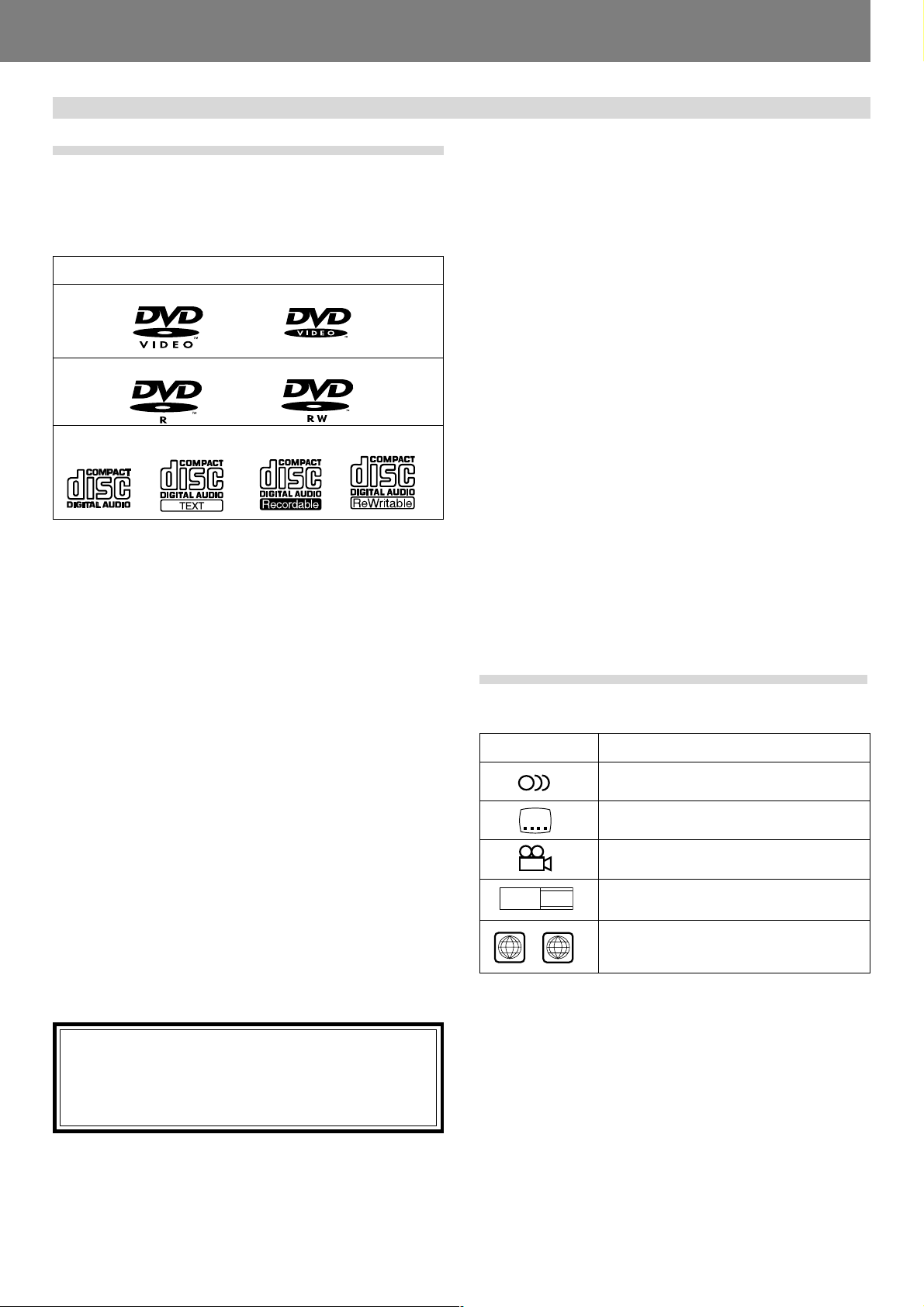
Types and Logos of playable discs
DVD video
(Note 1)
DVD-R
CD CD-TEXT
(Note 3)
DVD-RW
CD-R
Note 1) About DVD-R disc playback:
This player can play back DVD-R discs recorded in “DVD video”
format.
Note 2) About DVD-RW disc playback:
¶ This player can play back DVD-RW discs recorded in “DVD
video” format.
¶ When playing a disc that has been edited on a DVD recorder,
portions of the recording including links between tracks may
appear as a momentary still image.
¶ When playing a disc that has been recorded or edited on a
DVD recorder, the locations of edited portions may shift somewhat.
* For details, consult the Operating Instructions for your recorder.
Note 3) Regarding CD-TEXT display:
The number of characters that can be displayed is up to 72 for
disc title, and 48 for track titles. When a display exceeds 8 characters in length, the display will scroll. Only alpha-numerics and
a limited number of symbols can be displayed.
Note 4) CD-R/CD-RW discs:
This player can play CD-R/CD-RW discs recorded in audio CD
format.
* For details, consult the Operating Instructions for your recorder.
(Note 4)
(Note 2)
CD-RW
(Note 4)
■ The following discs cannot be played on this unit:
¶ DVD video discs not marketed for region “1” or “All”
¶ DVD-RW discs recorded in VR format
¶ DVD audio discs
¶ DVD-ROM
¶ DVD-RAM
¶ Video CDs
¶ CD-ROMs (MP3, etc.)
¶ Photo CD
¶ DTS-CD, etc.
Notes:
Some DVD-R/DVD-RW and CD-R/CD-RW discs recorded on
standalone recorders or computer drives may not be playable
back on this player, due to a variety of reasons, including disc
characteristics, scratches, dirt, player lens dirt or condensation, etc.
Some discs recorded on computer drives may not be playable
on this player, depending on the recording application used,
its settings, and operating environment. Be sure to use the
correct formatting for the discs used. For details, consult the
application author.
This unit cannot play DVD-R or DVD-RW discs recorded in
video format unless they have been finalized.
This unit cannot play DVD-RW discs recorded in VR format.
This unit cannot play partially recorded CD-R or CD-RW discs
that have not been finalized.
For detailed information regarding the handling of DVD-R/DVDRW and CD-R/CD-RW discs, consult the handling precautions
supplied with each disc.
Marks displayed on DVD
The following symbols and marks may be displayed on DVD
labels or packaging:
Mark Meaning
2
2
3
16 : 9 LB
ALL
1
Number of recorded audio tracks
Number of recorded subtitles
Number of recorded angles
Recorded aspect ratio
Region number. This player can play discs
marked with region “1” or “ALL”.
When playing 8cm CDs, always use an 8cm CD adapter
P. 34).
(☞
Note:
This player does not support playback of 8 cm DVDs. Do
not attempt to use adapters meant for 8 cm CDs, since the
adapter may come loose during rotation, causing damage
to the disc or component.
9
Before Operating (Discs Usable with This Unit)
DVD operating limitations
Some DVDs are designed explicitly to prevent the use of certain
operations or to prevent changing operation methods. As a result, the methods used to operate each disc may vary, and some
techniques may not be usable with certain discs. In the event
that a prohibited technique is attempted with a disc on this player,
the display will show the disc operation prohibited mark
certain other operations may not be supported on discs that support menus or dialogue-type operations during playback. In such
cases, the player operation prohibited mark
will be displayed.
. Also,
Regarding copyright
¶ Unauthorized copying, broadcasting, public performance, or
rental of copyrighted discs is prohibited by law.
¶ This product incorporates copyright protection technology
that is protected by method claims of certain U.S. patents
and other intellectual property rights owned by Macrovision
Corporation and other rights owners. Use of this copyright
protection technology must be authorized by Macrovision Corporation, and is intended for home and other limited viewing
uses only unless otherwise authorized by Macrovision Corporation. Reverse engineering or disassembly is prohibited.
Disc composition
Digital Versatile Discs (DVD)
DVD video, DVD-R or DVD-RW discs are recorded in units called
“titles,” with each title being divided into one or more sub-divisions called “chapters.” Further, some, discs are furnished with
menus for navigating the disc, but menus may not be included
with all titles. In the case of commercial films, a single movie
normally corresponds to a single title. On so-called “karaoke”
discs, each song track composes a single title, although there
are some exceptions to this rule, so care is needed when using
search functions.
Title 1 Title 2
Chapter 1 Chapter 2 Chapter 1 Chapter 2
DVD/DVD-R/DVD-RW
Compact Discs (CD)
In the case of compact discs, each disc is divided into units of
individual tracks (normally, each song is contained on a single
track). In addition, tracks may have sub-divisions called index
numbers.
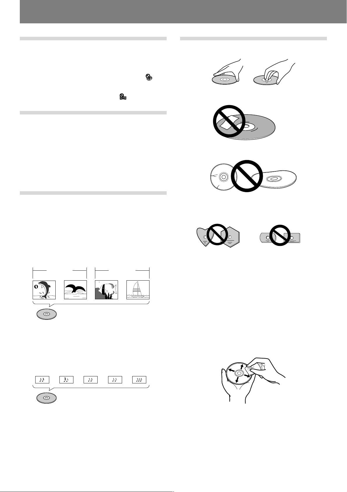
Handling discs
■ When holding discs, do not touch their signal surfaces. Hold
by the edges, or by one edge and the center hole.
■ Do not affix gummed labels or tape to the disc surface. Also,
do not scratch or damage the label.
■ Discs rotate at high speeds inside the player. Do not use dam-
aged, cracked or warped discs.
■ Do not play a disc with a special shape
¶ Do not play a disc having other shape than a circular disc,
such as heart shaped disc. Otherwise malfunction may occur.
■ Storing discs
¶ Discs are made of the same kinds of plastic used for con-
ventional analog audio records. Be careful not to allow discs
to warp. Always store discs in their cases vertically, avoiding
locations with high heat, humidity, or extremely low temperatures. Avoid leaving discs in cars; the interior of a car in
direct sunlight can become extremely hot.
¶ Always read and abide by the precautionary notes listed on
disc labels.
■ Cleaning discs
¶ Always keep your discs clean by wiping them gently with a
soft cloth from the inner edge toward the outer edge.
¶ When cleaning discs, the use of a commercial CD/DVD clean-
ing kit is recommended.
Track 1 Track 2 Track 3 Track 4 Track 5
CD
10
¶ If a disc becomes very dirty, dampen a soft cloth with water,
(be sure to wring it out well) and wipe the away dirt gently.
Remove any water drops with another soft, dry cloth.
¶ Do not use record cleaning sprays or anti-static agents on discs.
Never clean discs with benzene, thinner, or other volatile solvents or damage to the disc surface may result.
Before Operating (Names and Functions of Parts)
Names and Functions of Parts
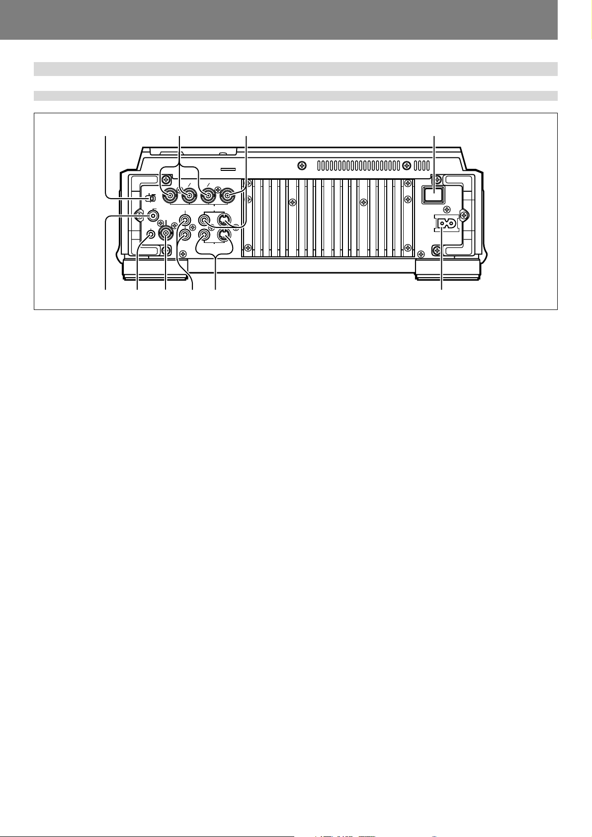
Rear panel
1234
NORMAL
MODE
CONTROL
DJ
DIGITAL
OUT
SYNC IN
YCBCRP
AUDIO OUT VIDEO OUT
P
B
L
R
R
PREVIEW OUT
COMPOSITE
S
S
56789 10
1. POWER OFF (—)/ON (_) switch
2. Main video output connectors (VIDEO OUT)
Includes RCA and BNC type connectors for outputting DVD
playback video only (composite signals), as well as S-Video
output connector.
3. Component video output connectors (Y, C
BNC type connectors for component signal output of DVD
playback video only. Produces higher image quality than composite output.
4. Mode select switch (MODE NORMAL/DJ) (☞ P.17)
If this switch position is changed during playback, playback
will stop, and then resume playback from the disc’s beginning.
DJ: Allows use of jog dial operations, tempo variations and
other DJ functions. During DVD playback, no signal is output
from digital output connectors. Also, subtitles and certain
other functions and operations are not supported, and some
points cannot be played. During CD playback, only audio data
are output from digital connectors.
NORMAL: DJ functions are not supported. Pause mode is
silent, not audible. During DVD playback, selected audio signals are output from the digital output connectors. During
CD playback, digital data containing subcodes are output (does
not support CD graphics).
5. DIGITAL OUT connector
RCA type coaxial digital output, for connecting AV amplifier,
Dolby Digital/DTS decoder, CD recorder, etc.
When mode select switch (4) is set to “DJ”, no signal is
output from this connector during DVD playback. During CD
playback, only audio data without subcodes are output.
When mode select switch (4) is set to “NORMAL”, this
connector outputs digital data including subcodes.
B/PB, CR/PR)
6. CONTROL connector
Using the supplied accessory control cord, this connector can
be connected to a Pioneer DJ mixer (DJM-600, DJM-500,
DJM-300, DJM-909, DJM-707 or DJM-3000) to allow control
of this unit from the DJ mixer. This facilitates the use of func-
tions such as fader start play and back cue.
Alternately, linking this connector to another DJ player allows
automatic relay play (☞ P.42).
7. SYNC IN connector
BNC type input connector for inputting external sync signal.
Use to connect an optional sync signal generator.
8. AUDIO OUT L,R connectors
RCA type analog audio output connectors.
9. Preview video output connectors (PREVIEW OUT)
RCA type connector (composite signals) and S-Video output
connector. These connectors output monitor images used to
aid the DJ during operation. Outputs various guide messages
and displays (☞ P.15).
10. AC inlet
Use auxiliary power cord to connect to standard electrical
outlet.
11
Before Operating (Names and Functions of Parts)
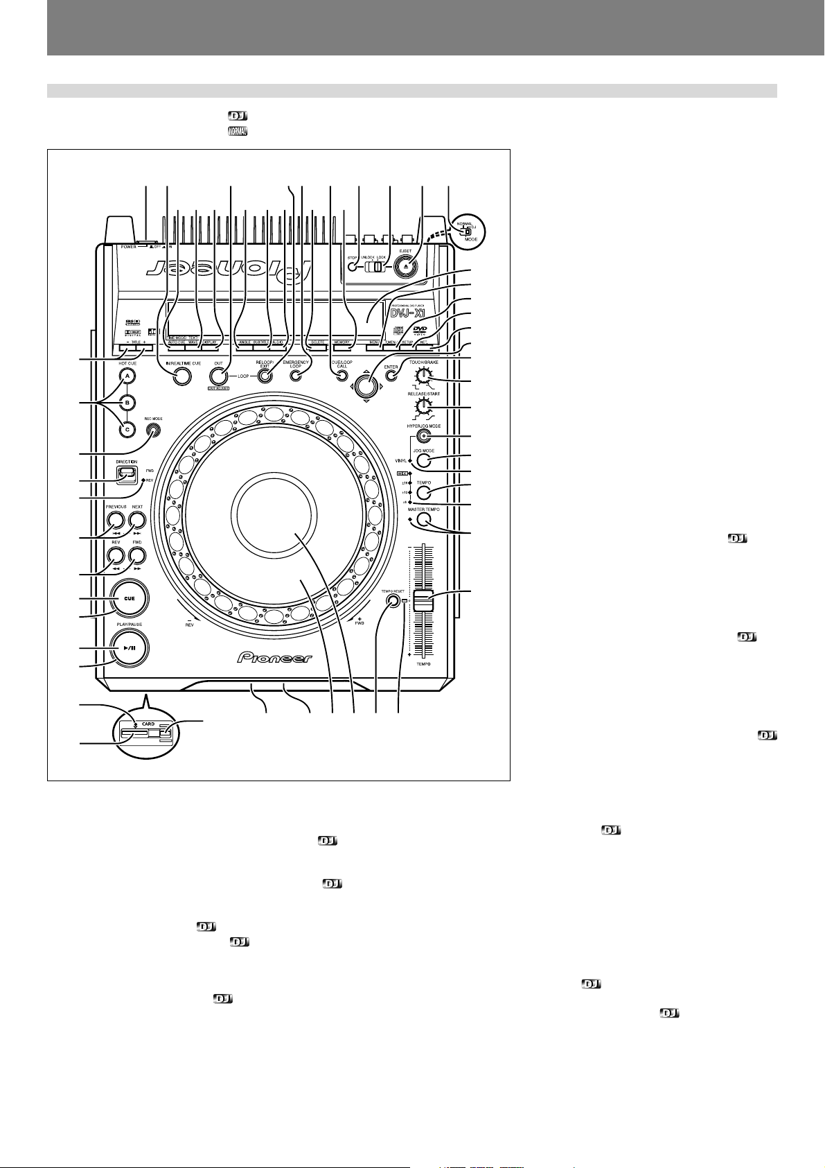
Operation panel
Buttons and controls with the mark are disabled when the mode select switch is set to NORMAL.
Buttons and controls with the
12 3 45 6 7 8 910
40 41 42 43 44 45 46 47
39
38
37
36
35
34
33
32
31
30
29
28
27
1. POWER OFF (—)/ON (_) switch
Located on the rear panel.
2. LOOP IN/REALTIME CUE button/indicator
Real time cue ☞ P.38
Loop-in point input ☞ P.41
3. LOOP OUT/OUT ADJUST button/indicator
Loop-out point input ☞ P.41
Loop-out point adjust ☞ P.41
4. RELOOP/EXIT button ☞ P.41
5. EMERGENCY LOOP button ☞ P.41
When this button is pressed, the current point is set as a loop-in
point; a loop-out point is set automatically and loop play begins between the two points.
6. CUE/LOOP CALL button ☞ P.45
Press to turn cue point navigation mode ON/OFF.
mark are disabled when the mode select switch is set to DJ.
7. STOP button
Stops disc playback. When the eject/stop mode
select switch is set to LOCK, playback will not
stop unless the PAUSE mode is set first.
8. Eject/stop mode select switch
(UNLOCK/LOCK)
UNLOCK: If the EJECT (0) button is pressed
during playback, the disc stops and is ejected.
48
49
50
51
52
53
54
11
If the STOP button is pressed during playback,
the disc playback stops.
LOCK: If the EJECT (0) button is pressed dur-
ing playback, the disc will not be ejected. To
eject the disc, set the unit to pause, then press
the EJECT (0) button. Likewise, playback will
not stop if the STOP button is pressed during
playback; to stop disc playback, set the unit to
pause, then press the STOP button.
9. EJECT (0) button
12
13
14
15
16
17
18
19
When this button is pressed, disc rotation stops
and the disc is ejected from the loading slot. If
the eject/stop mode select switch is set to the
LOCK position, the disc will not be ejected unless the unit is set to pause before pressing the
EJECT (0) button (☞ P.34).
10. Mode select switch
(MODE NORMAL/DJ) ☞
Located on the rear panel.
11. TOUCH/BRAKE response dial
Adjusts the disc deceleration speed (time to
playback stop) when the jog dial’s top surface
is touched with jog mode set to VINYL ON. Rotate the dial counterclockwise to stop playback
quickly, and rotate dial clockwise to cause
slower deceleration.
12. RELEASE/START response dial
Adjusts the disc acceleration speed (playback
startup time) when the jog dial’s top surface is
released with jog mode set to VINYL ON. Rotate the dial counterclockwise to restart playback quickly, and rotate dial clockwise to cause
212223242526
20
slower acceleration.
13. HYPERJOG MODE button/indicator
When hyper jog mode is set to ON with jog mode
set to VINYL ON, turning the jog dial causes the
rate of change of image and sound to increase
to 2x the rate of changed normally produced
(when the hyper jog mode is OFF).
14. JOG MODE select button
Each time pressed, sets VINYL mode alternately ON/OFF.
VINYL mode ON: If surface of jog dial is touched during playback,
playback stops, and if the dial is then rotated, image and sound are
output in response to the amount of rotation. (if the angled surface
of the jog dial is rotated without touching the top, pitch bend operation is enabled.)
¶ The current jog mode is memorized even when power is turned
off.
VINYL mode OFF: The above operations are disabled even when
the jog dial’s surface is touched.
15. VINYL mode indicator
Lights when the jog mode is set to VINYL mode.
16. TEMPO control range select button
Each time this button is pressed, the TEMPO control slider’s vari-
able range changes (±6%, ±10%, ±16%, WIDE).
When WIDE is selected, the variable range is +70 to –100% for DVD
playback, and ±100% for CD playback.
P.11
12

Before Operating (Names and Functions of Parts)
17. TEMPO control range indicator (±6, ±10, ±16, WIDE)
¶ When control range is set to ±6%, the ±6 indicator lights.
¶ When control range is set to ±10%, the ±6 and ±10 indicators
light.
¶ When control range is set to ±16%, the ±6, ±10 and ±16 indica-
tors light.
¶ When control range is set to WIDE, the ±6, ±10, ±16 and WIDE
indicators light.
18. MASTER TEMPO button/indicator ☞ P.39
Each time this button is pressed, the master tempo function turns
alternately ON/OFF.
19. TEMPO control slider
When pulled forward (+), playback tempo is accelerated, and when
pushed away (–), tempo is slowed.
20. TEMPO RESET indicator
When lighted, indicates that the playback tempo is set to normal
tempo “0”, regardless of the position of the TEMPO control slider.
21. TEMPO RESET button
Pressing this button instantly resets the playback tempo to “0” (normal tempo), regardless of the current position of the TEMPO control
slider. Press the button once again to cancel the reset.
22. Jog dial display ☞ P.15 (30-34)
23. Jog dial (FWD+/REV–) ☞ P.39
24. Disc loading slot ☞ P.34
25. Forced eject hole ☞ P.34
26. Memory card eject button ☞ P.44
Press to remove memory card.
¶ Do not press when the memory card indicator is lighted.
27. Memory card slot ☞ P.44
28. Memory CARD indicator ☞ P.44
Lights when unit is accessing the memory card.
¶ Do not remove memory card or turn off power when this indicator
is lighted.
29. PLAY/PAUSE indicator
Lights during playback, and flashes during pause mode.
30. PLAY/PAUSE (3/8) button ☞ P.35
31. CUE indicator ☞ P.38
Lights to indicate a cue point has been set. Flashes during pause
mode.
32. CUE button
Cue point setting ☞ P.38
Back cue ☞ P.38
Cue point sampler ☞ P.38
33. Manual search buttons (REV1, FWD¡) ☞ P.37
34. Track search buttons
(PREVIOUS 4, NEXT ¢)
Use to return or advance play (unit of movement is by tracks when
playing CDs, and by chapters when playing DVDs).
During DVD playback, use to return to menu page or change page.
☞ P.37
35. REV indicator
Lights when direction select switch is set to reverse.
36. DIRECTION FWD/REV select switch
Set to REV position for reverse playback.
37. HOT CUE REC MODE button ☞ P.40
Press to select the HOT CUE button’s function (record/call).
¶ Defaults to call mode when power is switched on.
38. HOT CUE (A, B, C) buttons/indicators ☞ P.40
A, B, or C indicator lights red to indicate hot cue point record mode.
A, B, or C indicator lights green for hot cue point, and orange for hot
cue point; when an indicator is lighted, call mode is enabled for that
point; pressing the button initiates playback from the hot cue point.
When indicator is not lighted, no hot cue point is recorded.
39. Title search buttons (TITLE +/–) ☞ P.37
During DVD playback, titles are forwarded or reversed in the direction corresponding to the button pressed.
40. TIME MODE/AUTO CUE button
TIME MODE:
Each time the button is pressed, the time display switches alternately between playback elapsed time and remaining time (REMAIN).
¶ The time mode remains set in memory even when power is turned
off.
AUTO CUE:
Hold depressed for one second or more to set/release the auto cue
function.
Hold depressed for five seconds or more to switch the auto cue
level (☞ P.35).
¶ The auto cue ON/OFF setting and auto cue level remains set in
memory even when power is turned off.
41. TEXT/WAVE select button
When pressed in DJ mode, the display alternates between WAVE
display and CD-TEXT display (disc title / track title).
When pressed in NORMAL mode, alternates between CD-TEXT disc
title / track title display.
42. DISPLAY button ☞ P.15, P.43
When pressed in DJ mode, turns the hot cue, cue point, and playback time guide display ON/OFF on the monitor connected to the
preview video output connector.
When pressed in NORMAL mode, turns the disc information guide
display ON/OFF.
¶ When power is switched ON, the display function defaults to ON
when the unit is in the DJ mode, and OFF (no display) in the NOR-
MAL mode.
43. ANGLE button
Press to change the viewing angle during DVD playback (on supported discs only).
¶ In DJ mode, when the angle is changed both video and audio
playback temporarily stop (due to writing to buffer memory).
44. SUBTITLE button
During DVD playback, press to alternately turn subtitle display ON/
OFF (on supported discs only).
¶ This function is disabled in DJ mode.
45. AUDIO button
During DVD playback, press this button to change language or audio
channel (on supported discs only).
¶ In DJ mode, when the language/audio channel is changed, both
video and audio playback temporarily stop (due to writing to buffer
memory).
46. DELETE button ☞ P.47
Press to delete cue points and loop points recorded in SD memory
card.
47. MEMORY button ☞ P.44
Press to store cue points or loop points in SD memory card.
48. Display ☞ P.14 (1-29)
49. MENU button
Press to display DVD menu.
50. Top menu (T.MENU) button
Press to display a DVD’s top menu level.
51. SETUP button ☞ P.20
Press to display the setup menu.
52. Return (RET.) button
When setup or other menus are displayed, press this button to return to the previous menu or item.
53. Cursor button (2/3/5/∞)
Press to select cue points navigation and DVD menu settings.
54. ENTER button
Press to confirm cue point navigation and various DVD input settings.
13

Before Operating (Names and Functions of Parts)
Display
12345678910111213 14 15
29 28 27 26 25 24 23 22 21 20 19 18 1617
1. Title number (TITLE 00-99)
Indicates the DVD title number.
Not displayed during CD playback.
2. Chapter number (CHP 000-999)
Indicates the DVD chapter number.
“CHP” is not displayed during CD playback.
3. Track number (TRACK 00-99)
Indicates CD track number.
“TRACK” is not displayed during DVD playback.
4. Prohibited indicator ( )
Some DVD discs or players do not support certain functions or operations; if an effort is made to perform such operations, this indicator appears for about 2 seconds.
5. Angle indicator ( )
During DVD playback, this mark appears to indicate a scene with
variable angle.
6. Auto cue (A.CUE) indicator
Lights when auto cue is ON. Does not light during NORMAL mode.
7. Remaining time (REMAIN) indicator
Indicates that the current numerical display is of a track’s remaining
time.
8. SRS indicator ( )
Lights when TruSurround function is selected. This function is disabled in DJ mode.
9. Disc indicator ( )
Lights during display of a CD TEXT disc title.
10. Minutes display (000-999 M)
11. Seconds display (00-59 S)
12. Frame display (00-74 F)
Display audio frame numbers. 75 frames are equivalent to one second of normal play. Not displayed in NORMAL mode.
13. Video frame display (00-29 VIDEO F)
Lights during DVD playback in DJ mode. 30 frames are equivalent to
one second. Video frame display does not appear during CD playback and in NORMAL mode.
Since this unit controls video frames (1/30 second) based on the
audio frame (1/75 second), combining the two will result in a maximum deviation of 1 frame.
14. TEMPO indicator
Displays tempo variation produced when TEMPO control slider is
operated.
15. EJECT LOCK indicator
Lights when eject/stop mode select switch is set to LOCK position.
If the EJECT (0) button or STOP button is pressed when this indicator is lighted, the indicator will flash for about 2 seconds.
16. Tempo control range display (±6, ±10, ±16, WIDE)
Lights to indicate the TEMPO control slider’s variable range as se-
lected with the tempo control range select button. Does not light in
NORMAL mode.
17. Master tempo indicator (MT)
Lights when master tempo function is ON.
Does not light in NORMAL mode.
14
18. BPM counter display
Lights to indicate the beats per minute (BPM) of the currently playing track. Some tracks may not be measurable with the automatic
BPM counter.
Does not light in NORMAL mode.
19. Dot matrix display (50x7 dots)
Used to display CD TEXT, WAVE display, guide messages and other
data. In the case of CD TEXT, the maximum number of alpha-numeric characters that can be displayed is 72 for disc titles and 48 for
track titles (when a display exceeds 9 characters in length, the display will scroll). In the case of WAVE display, the varying volume
levels of the currently playing track are displayed, with the track sized
to fit into the entire 50-dot display width.
For guide messages, see P.51 “Dot Matrix Guide Display Mes-
sages”.
20. Play address display
Displays a bar graph to allow an immediate visual grasp of the elapsed
and remaining playing time of the currently playing track. The full
scale bar length indicates the full track length.
¶ The bar graph is off at the beginning of the track, and lights from
left to right.
¶ The bar graph is lighted at the beginning of the track, and goes out
from left to right.
¶ When the remaining playing time falls below 30 seconds, the bar
graph flashes slowly; when less than 15 seconds are left, the bar
graph flashes quickly.
21. Cue memory indicator (M.CUE)
The selected chapter or track’s cue memory position is indicated by
the indicators beneath the play address display. Even if multiple
memory points are located within the same block, only a single indicator lights. Does not light in NORMAL mode.
22. Loop memory indicator (M.LOOP)
Displays the loop memory position for the selected track immediately above the playback address display. Even if multiple memory
points are located within the same block, only a single indicator lights.
Does not light in NORMAL mode.
23. RELOOP indicator
Lights when loop-in points and loop-out points have been recorded
and loop playback is possible, as well as during loop play operation
itself.
Does not light in NORMAL mode.
24. EMERGENCY LOOP indicator
Lights during loop operation in emergency loop mode.
Does not light in NORMAL mode.
25. DTS indicator
Lights during playback when DTS audio has been selected.
Not supported in DJ mode.
26. GUI indicator
Lights when setup menu, image adjust, disc information and other
onscreen menus are displayed.
27. Dolby Digital indicator (2 D)
Lights during playback when Dolby Digital audio has been selected.
28. Disc type indicator (DVD/CD)
Lights to indicate the type of disc being played.
29. Reverse indicator (REV)
Lights to indicate the Direction select switch is set to reverse (REV)
position.
Does not light in NORMAL mode.
Before Operating (Names and Functions of Parts)
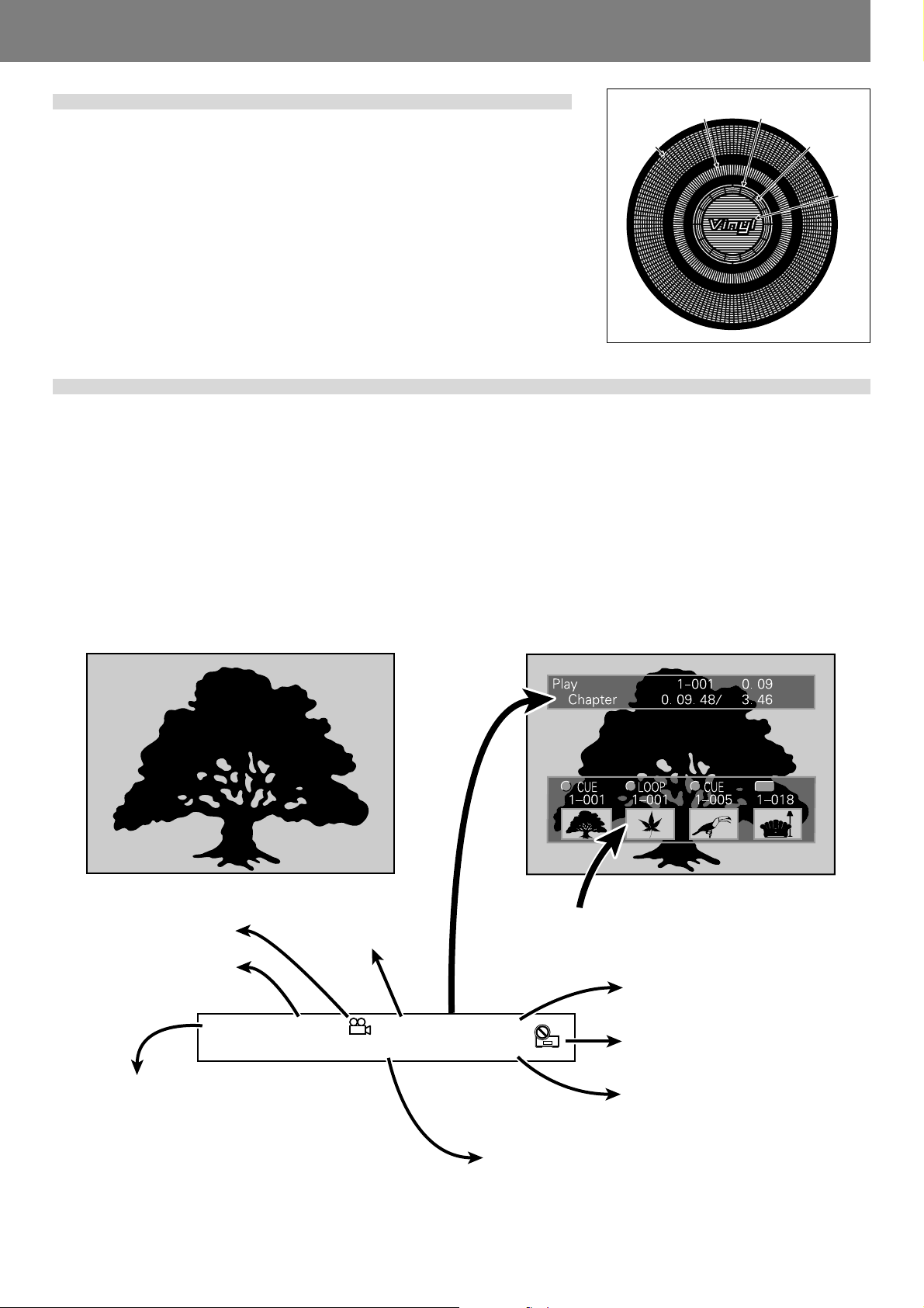
Jog dial display
31 32
30. Operation display
Displays play position, with one revolution equivalent to 135 frames. The display rotates
during playback, and stops during pause.
31. Cue point position display
Displays the position of cue points.
32. Audio/video memory status display
Flashes during writing to the audio/video memory; lights steadily when writing is completed.
While indicator is flashing, it may not be possible to record real time cue points or hot cue
points.
33. Jog touch detector indicator
When VINYL mode is set to ON, this indicator lights when the top panel of the jog dial is
touched.
34. VINYL mode indicator (Vinyl)
Lights when VINYL mode is set to ON.
30
33
34
Playing images from the DVJ-X1 on a television set
★ The example shown here is an illustration meant to depict the general display contents, and may differ somewhat from actual monitor
appearance.
This unit is equipped with both main video output (VIDEO OUT) and preview video output (PREVIEW OUT) connectors.
In NORMAL mode, both VIDEO OUT and PREVIEW OUT produce the same video signals.
In DJ mode, the outputs of the two connectors are different, as indicated below. Even in DJ mode, however, if a non-supported DJ
operation is attempted, the outputs will be the same as in NORMAL mode.
■ VIDEO OUT
This outputs only the DVD playback image; it should be connected to the main publicly viewed monitor.
■ PREVIEW OUT
This outputs the images used by the DJ when operating the unit, and includes various additional guide messages and menus.
Main monitor image
Angle
indicator
In reverse mode
displays “REV”
indicator
Play
Title number,
chapter number
REV
1–010 40. 20
Chapter 3. 45. 67/
Guide
display area
4. 56
Preview monitor image
CBA
Sub-screen for displaying points memorized in
HOT CUE and CUE buttons
Elapsed time within title
“Prohibited” mark and other
indicators
CUE
Status indicator
Play: Normal playback
Loop: Loop playback
Cue: Cue standby
Pause: Normal pause (standby)
Scratch: Scratch operation
Search: Chapter/track search
¡: Forward search (scan)
1: Reverse search (scan)
Reading: Recall hot cue, or cue point
Total time in chapter (minutes / seconds)
Chapter contents are displayed as minutes, seconds,
and frames. When time mode is set to REMAIN, displayed numbers are preceded with a “minus” (–) symbol, for example, “-1.10.08”.
15
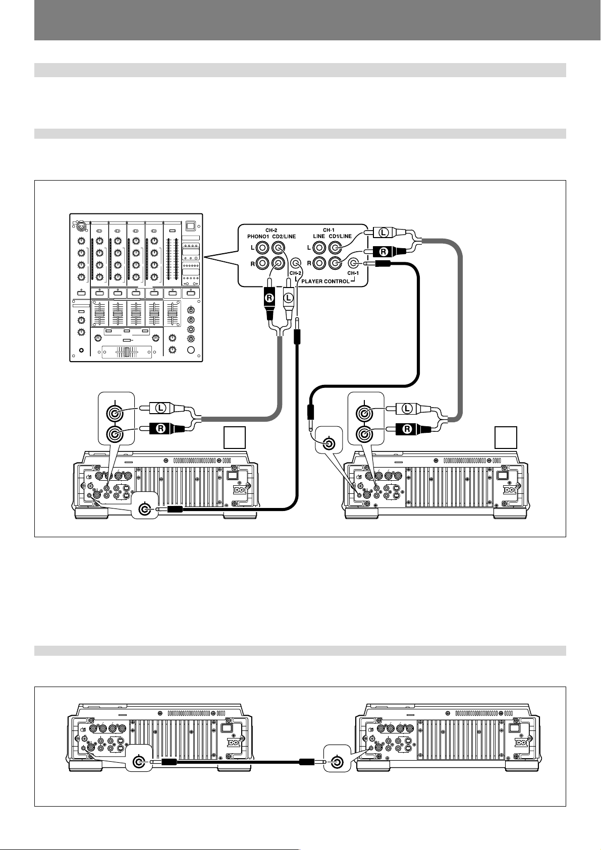
Before Operating (Connections)
Connections
Before making or changing the connections, switch off the power and disconnect the power cord from the AC outlet.
1. Connections to DJ mixer (DJM-600, DJM-500, DJM-300, DJM-909, DJM-707
or DJM-3000) (audio output and control connector)
Using the accessory audio cable, connect the white plug to the L (left) connector, and connect the red plug to the R (right) connector.
By connecting the accessory control cord, the player can be controlled from the mixer, allowing fader start play and back cue operations.
Connection example DJM-600:
DJM-600
Accessory
audio cable
Accessory control cord
AUDIO OUT
YCBCRPRP
NORMAL
DJ
MODE
DIGITAL
AUDIO OUT VIDEO OUT
OUT
SYNC IN
CONTROL
L
R
DVJ-X1
B
COMPOSITE
L
S
R
S
PREVIEW OUT
A
NORMAL
CONTROL
DJ
MODE
DIGITAL
AUDIO OUT
YCBCRPRP
AUDIO OUT VIDEO OUT
OUT
SYNC IN
L
R
DVJ-X1
B
COMPOSITE
L
S
R
S
CONTROL
PREVIEW OUT
B
CONTROL
¶ Connect similarly to the above when using DJM-300 or DJM-500.
¶ When connecting DJM-909 or DJM-707, use the accessory audio cable to connect CH-1 CD to PLAYER A, and the CH-2 CD to
PLAYER B.
¶ In the case of the DJM-3000, connect A PLAYER to LINE 1 of CH-1, connect B PLAYER to LINE 3 of CH-2.
¶ When connecting this player to other audio mixers, the player’s AUDIO OUT connector should be connected to the mixer’s LINE IN
connector or AUX connector (★ Do not connect the player to a mixer’s PHONO connector, since sound will be distorted and
proper playback will not result).
2. Control cord connection for relay play
By using the accessory control cord to connect two DJ players, automatic relay play can be performed between the two units. (☞ P.42)
DVJ-X1 DVJ-X1
YCBCRPRP
B
AUDIO OUT VIDEO OUT
OUT
SYNC IN
COMPOSITE
L
S
R
S
PREVIEW OUT
CONTROL
CONTROL
NORMAL
DJ
MODE
DIGITAL
CONTROL
Accessory control cord
YCBCRPRP
B
AUDIO OUT VIDEO OUT
OUT
SYNC IN
COMPOSITE
L
S
R
S
PREVIEW OUT
NORMAL
DJ
MODE
DIGITAL
CONTROL
16
 Loading...