

Pioneer DEH-3900-MP Service manual
ORDER NO.
CRT3804
DEH-3900MP/XN/EW5
CD RDS RECEIVER
DEH-3900MP
This service manual should be used together with the following manual(s):
Model No. Order No. Mech.Module Remarks
CX-3195 CRT3815 S10.5COMP2 CD Mech. Module : Circuit Descriptions, Mech. Descriptions, Disassembly
/XN/EW5
For details, refer to "Important Check Points for Good Servicing".
PIONEER CORPORATION 4-1, Meguro 1-chome, Meguro-ku, Tokyo 153-8654, Japan
PIONEER ELECTRONICS (USA) INC. P.O. Box 1760, Long Beach, CA 90801-1760, U.S.A.
PIONEER EUROPE NV Haven 1087, Keetberglaan 1, 9120 Melsele, Belgium
PIONEER ELECTRONICS ASIACENTRE PTE. LTD. 253 Alexandra Road, #04-01, Singapore 159936
PIONEER CORPORATION 2006
K-ZZA.NOV. 2006 Printed in Japan
1234
SAFETY INFORMATION
This service manual is intended for qualified service technicians; it is not meant for the casual do-it-yourselfer.
Qualified technicians have the necessary test equipment and tools, and have been trained to properly and safely
A
repair complex products such as those covered by this manual.
Improperly performed repairs can adversely affect the safety and reliability of the product and may void the warranty.
If you are not qualified to perform the repair of this product properly and safely, you should not risk trying to do so
and refer the repair to a qualified service technician.
- Safety Precautions for those who Service this Unit.
• When checking or adjusting the emitting power of the laser diode exercise caution in order to get safe, reliable
results.
B
Caution:
1. During repair or tests, minimum distance of 13 cm from the focus lens must be kept.
2. During repair or tests, do not view laser beam for 10 seconds or longer.
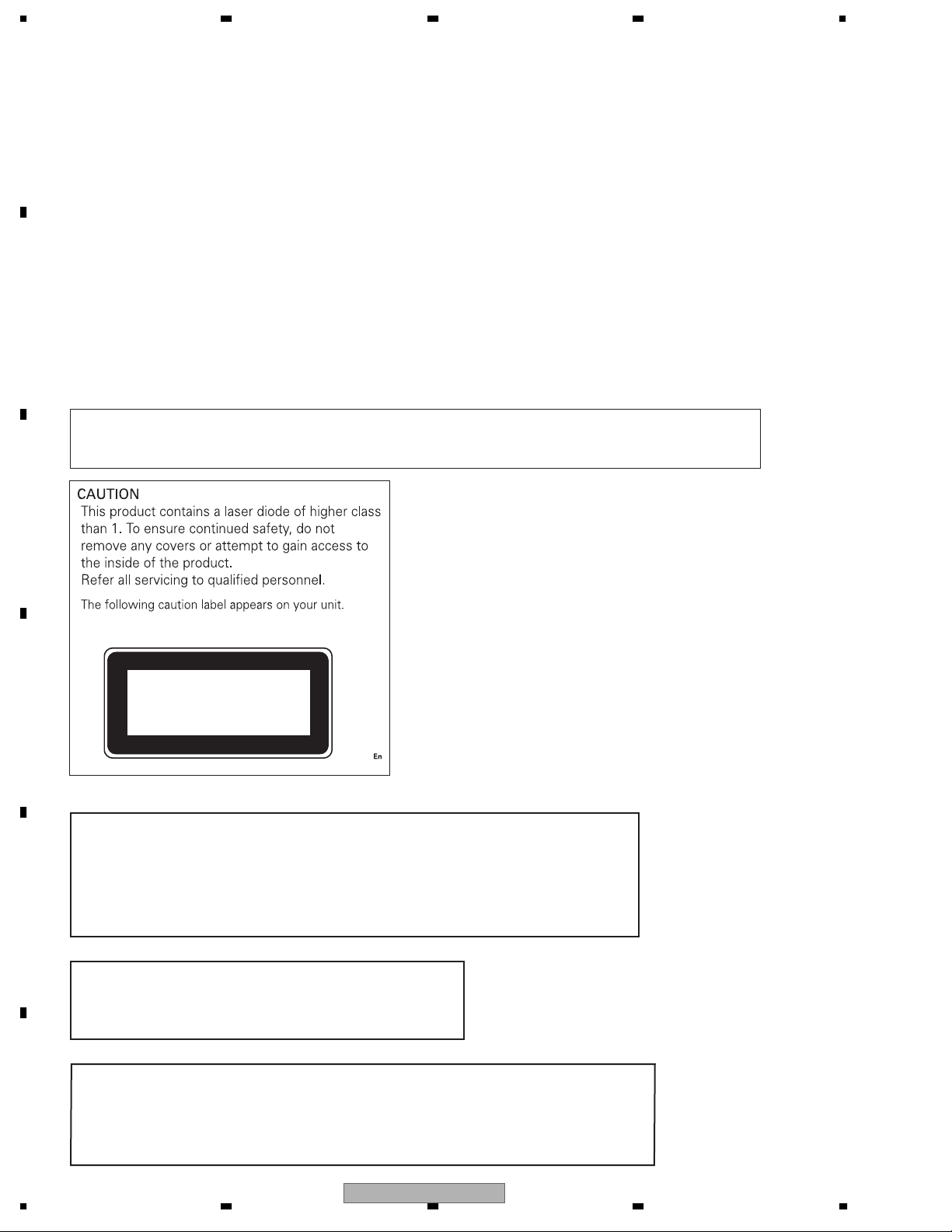
CAUTION:
USE OF CONTROLS OR ADJUSTMENTS OR PERFORMANCE OF PROCEDURES OTHER THAN THOSE
SPECIFIED HEREIN MAY RESULT IN HAZARDOUS RADIATION EXPOSURE.
C
CLASS 1
D
The AEL (accessible emission level )of the laser power output is less than CLASS 1
but the laser component is capable of emitting radiation exceeding the limit for
CLASS 1.
E
A specially instructed person should do servicing operation of the apparatus.
LASER PRODUCT
WARNING!
Laser diode characteristics
Wave length : 785 nm to 814 nm
Maximum output : 1 190 μW(Emitting period : unlimited)
Additional Laser Caution
F
Transistors Q101 in PCB drive the laser diodes.
When Q101 is shorted between their terminals, the laser diodes will radiate beam.
If the top cover is removed with no disc loaded while such short-circuit is continued,
the naked eyes may be exposed to the laser beam.
2
1234
DEH-3900MP/XN/EW5
5678
- Service Precaution
1. You should conform to the regulations governing
the product (safety, radio and noise, and other
regulations), and should keep the safety during
servicing by following the safety instructions
described in this manual.
2. Before disassembling the unit, be sure to turn off
the power. Unplugging and plugging the connectors
during power-on mode may damage the ICs inside
the unit.
3. To protect the pickup unit from electrostatic discharge
during servicing, take an appropriate treatment
(shorting-solder) by referring to "the DISASSEMBLY".
4. After replacing the pickup unit, be sure to check the
grating.
5. Be careful in handling ICs. Some ICs such as MOS
type are so fragile that they can be damaged by
electrostatic induction.
A
B
C
D
E
56
DEH-3900MP/XN/EW5
F
7
8
3
1234
[Important Check Points for Good Servicing]
In this manual, procedures that must be performed during repairs are marked with the below symbol.
Please be sure to confirm and follow these procedures.
A
B
C
D
1. Product safety
Please conform to product regulations (such as safety and radiation regulations), and maintain a safe servicing environment by
following the safety instructions described in this manual.
1 Use specified parts for repair.
Use genuine parts. Be sure to use important parts for safety.
2 Do not perform modifications without proper instructions.
Please follow the specified safety methods when modification(addition/change of parts) is required due to interferences such as
radio/TV interference and foreign noise.
3 Make sure the soldering of repaired locations is properly performed.
When you solder while repairing, please be sure that there are no cold solder and other debris.
Soldering should be finished with the proper quantity. (Refer to the example)
4 Make sure the screws are tightly fastened.
Please be sure that all screws are fastened, and that there are no loose screws.
5 Make sure each connectors are correctly inserted.
Please be sure that all connectors are inserted, and that there are no imperfect insertion.
6 Make sure the wiring cables are set to their original state.
Please replace the wiring and cables to the original state after repairs.
In addition, be sure that there are no pinched wires, etc.
7 Make sure screws and soldering scraps do not remain inside the product.
Please check that neither solder debris nor screws remain inside the product.
8 There should be no semi-broken wires, scratches, melting, etc. on the coating of the power cord.
Damaged power cords may lead to fire accidents, so please be sure that there are no damages.
If you find a damaged power cord, please exchange it with a suitable one.
9 There should be no spark traces or similar marks on the power plug.
When spark traces or similar marks are found on the power supply plug, please check the connection and advise on secure
connections and suitable usage. Please exchange the power cord if necessary.
0 Safe environment should be secured during servicing.
When you perform repairs, please pay attention to static electricity, furniture, household articles, etc. in order to prevent injuries.
Please pay attention to your surroundings and repair safely.
2. Adjustments
To keep the original performance of the products, optimum adjustments and confirmation of characteristics within specification.
Adjustments should be performed in accordance with the procedures/instructions described in this manual.
3. Lubricants, Glues, and Replacement parts
Use grease and adhesives that are equal to the specified substance.
E
Make sure the proper amount is applied.
4. Cleaning
For parts that require cleaning, such as optical pickups, tape deck heads, lenses and mirrors used in projection monitors, proper
cleaning should be performed to restore their performances.
5. Shipping mode and Shipping screws
To protect products from damages or failures during transit, the shipping mode should be set or the shipping screws should be
installed before shipment. Please be sure to follow this method especially if it is specified in this manual.
F
4
1234
DEH-3900MP/XN/EW5

5678
CONTENTS
SAFETY INFORMATION......................................................................................................................................2
1. SPECIFICATIONS .............................................................................................................................................6
2. EXPLODED VIEWS AND PARTS LIST.............................................................................................................8
2.1 PACKING....................................................................................................................................................8
2.2 EXTERIOR ...............................................................................................................................................10
2.3 CD MECHANISM MODULE .....................................................................................................................12
3. BLOCK DIAGRAM AND SCHEMATIC DIAGRAM ..........................................................................................14
3.1 BLOCK DIAGRAM....................................................................................................................................14
3.2 OVERALL CONNECTION DIAGRAM(GUIDE PAGE) ..............................................................................16
3.3 KEYBOARD UNIT ....................................................................................................................................22
3.4 CD MECHANISM MODULE(GUIDE PAGE).............................................................................................24
4. PCB CONNECTION DIAGRAM ......................................................................................................................32
4.1 TUNER AMP UNIT ...................................................................................................................................32
4.2 KEYBOARD UNIT ....................................................................................................................................36
4.3 CD CORE UNIT(S10.5COMP2) ...............................................................................................................38
5. ELECTRICAL PARTS LIST .............................................................................................................................40
6. ADJUSTMENT ................................................................................................................................................44
6.1 CD ADJUSTMENT ...................................................................................................................................44
6.2 CHECKING THE GRATING AFTER CHANGING THE PICKUP UNIT.....................................................46
6.3 ERROR MODE.........................................................................................................................................48
7. GENERAL INFORMATION .............................................................................................................................49
7.1 DIAGNOSIS..............................................................................................................................................49
7.1.1 DISASSEMBLY......................................................................................................................................49
7.1.2 CONNECTOR FUNCTION DESCRIPTION ..........................................................................................52
7.2 PARTS ......................................................................................................................................................53
7.2.1 IC ...........................................................................................................................................................53
7.2.2 DISPLAY................................................................................................................................................61
7.3 OPERATIONAL FLOW CHART................................................................................................................62
8. OPERATIONS .................................................................................................................................................63
A
B
C
D
E
F
56
DEH-3900MP/XN/EW5
7
8
5
1234
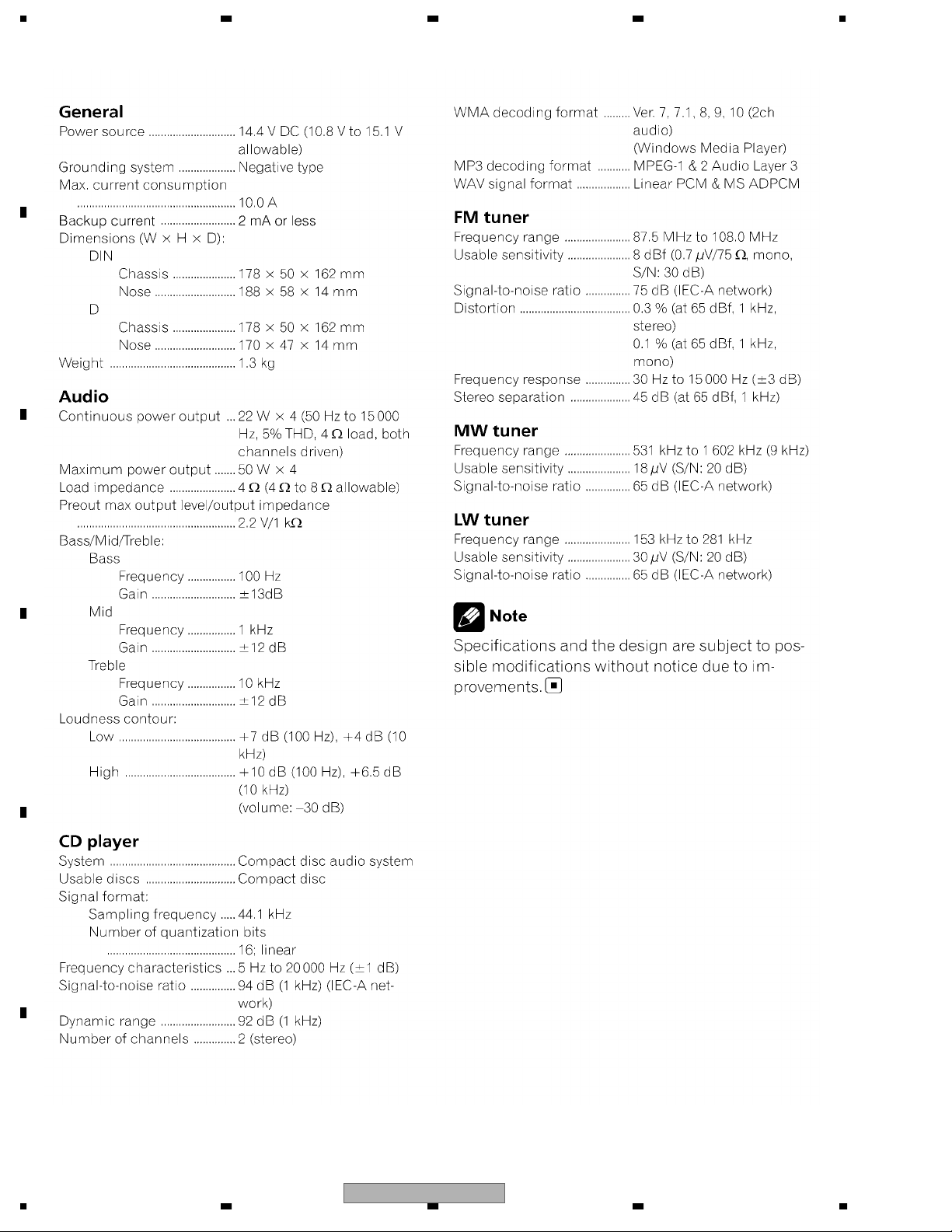
1. SPECIFICATIONS
A
B
C
D
E
F
6
1234
DEH-3900MP/XN/EW5

5678
A
B
C
D
E
56
DEH-3900MP/XN/EW5
F
7
8
7
N
1234
2. EXPLODED VIEWS AND PARTS LIST
OTES : • Parts marked by " * " are generally unavailable because they are not in our Master Spare Parts List.
• The > mark found on some component parts indicates the importance of the safety factor of the part.
A
Therefore, when replacing, be sure to use parts of identical designation.
• Screw adjacent to mark on the product are used for disassembly.
• For the applying amount of lubricants or glue, follow the instructions in this manual.
(In the case of no amount instructions,apply as you think it appropriate.)
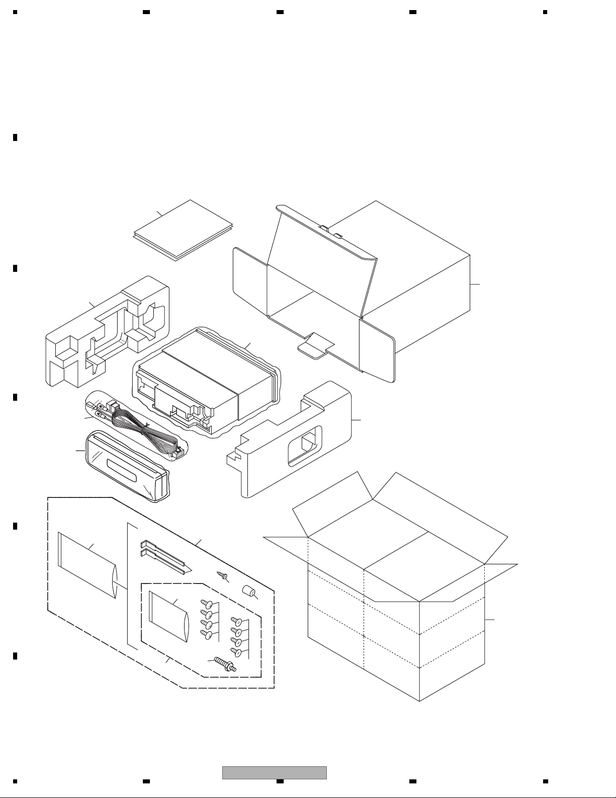
2.1 PACKING
"
B
16
C
1
18
18
D
17
13
12
15
9
E
4
F
8
1234
2
10
3
6
8
5
11
14
7
DEH-3900MP/XN/EW5
5678
PACKING SECTION PARTS LIST
Mark No. Description Part No.
1 Cord Assy CDP1015
2 Accessory Assy CEA6707
3 Screw BPZ20P080FTC
4 Screw Assy CEA3849
5 Screw CBA1650
* 6 Polyethylene Bag CEG-127
7 Screw CRZ50P090FTC
8 Screw TRZ50P080FTC
9 Polyethylene Bag CEG1160
10 Handle CND3707
11 Bush CNV3930
Owner's Manual,Installation Manual
Part No. Language
CRD4129 English, Spanish, German
CRD4130 French, Italian, Dutch, Russian
CRD4131 English, Spanish, German, French, Italian, Dutch, Russian
Mark No. Description Part No.
12 Polyethylene Bag CEG1373
13 Carton CHG5978
14 Contain Box CHL5978
15 Protector CHP3279
16 Protector CHP3280
17-1 Owner's Manual CRD4129
17-2 Owner's Manual CRD4130
17-3 Installation Manual CRD4131
* 17-4 Passport CRY1013
* 17-5 Warranty Card CRY1157
18 Case Assy CXB3520
A
B
C
D
E
56
DEH-3900MP/XN/EW5
F
7
8
9
1234
A
B
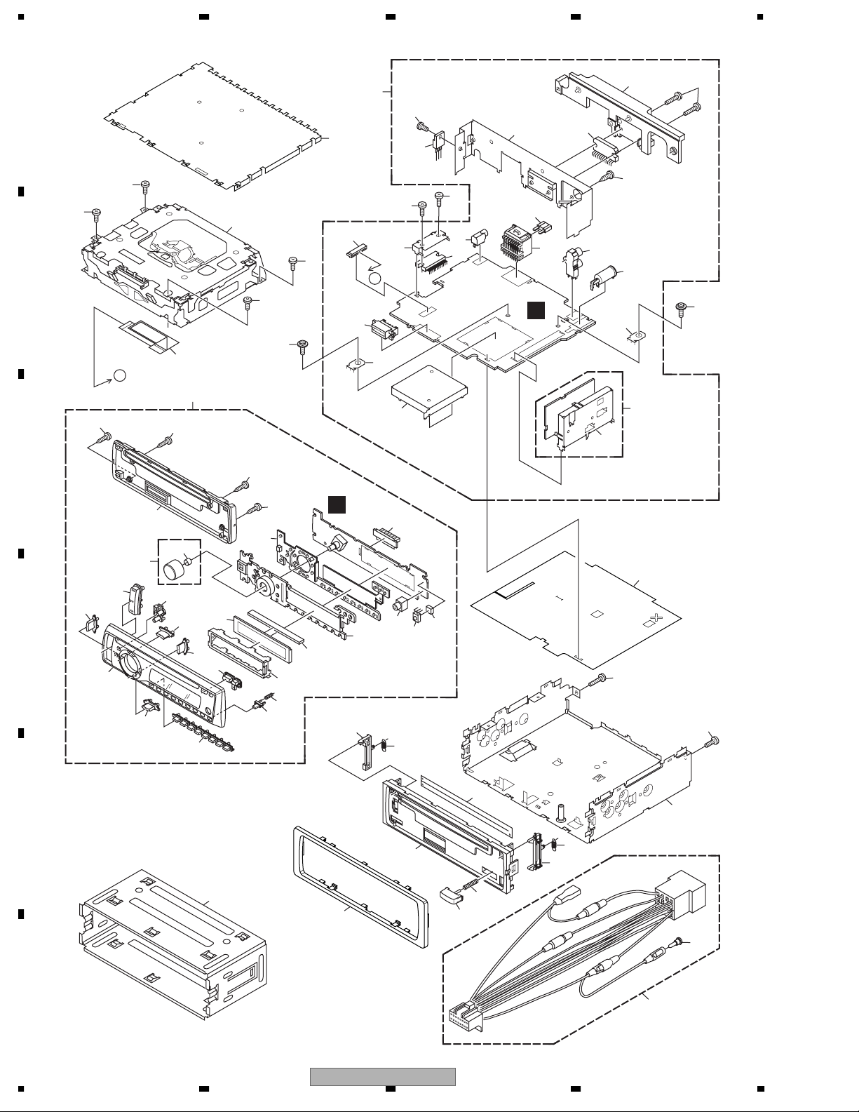
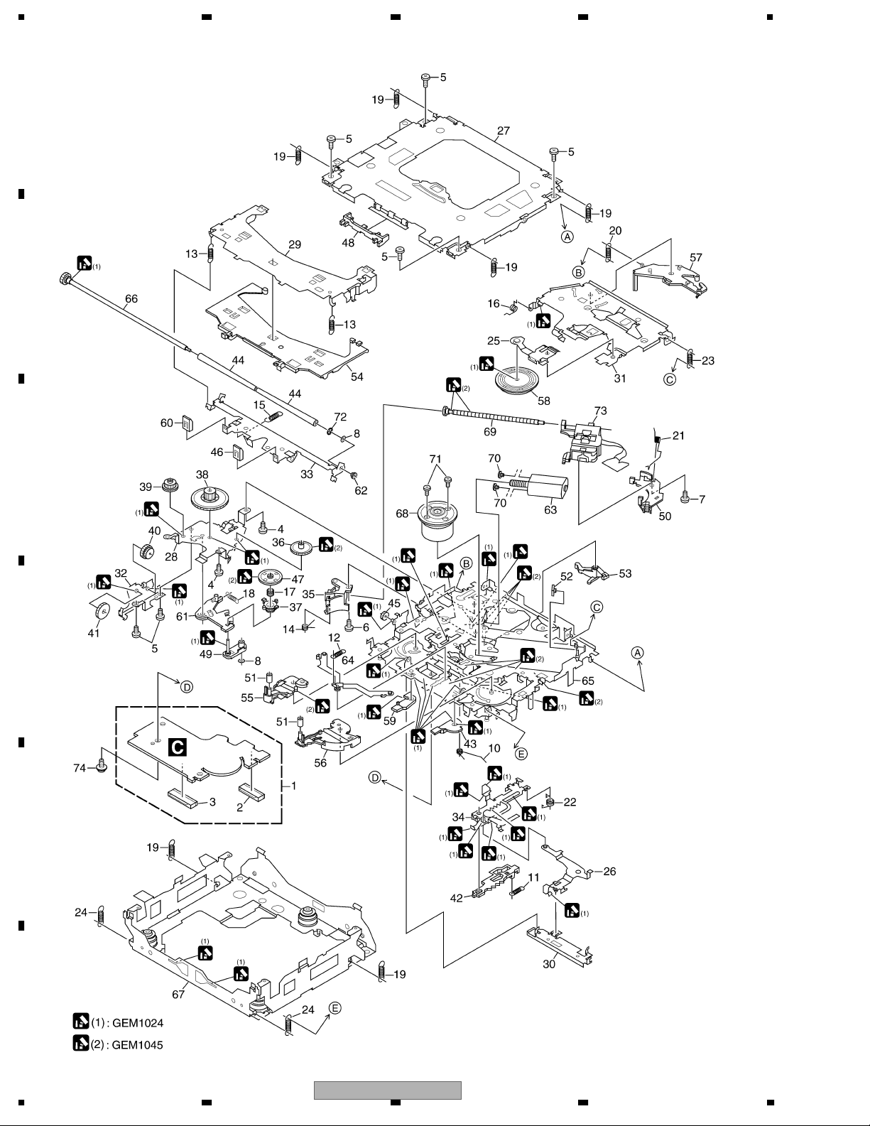
2.2 EXTERIOR
A
1
1
B
4
A
39
40
C
40
62
1
1
63
40
11
12
7
18
20
64
2
22
A
29
24
2
19
66
23
15
65
17
25
13
16
21
28
26
27
14
63
57
41
40
49
54
55
10
38
56
52
53
34
36
67
9
58
3
2
35
30
33
37
32
31
50
61
60
42
46
D
59
E
48
45
47
43
46
51
44
8
6
F
10
1234
DEH-3900MP/XN/EW5
5

5678
EXTERIOR SECTION PARTS LIST
Mark No. Description Part No.
1 Screw BSZ26P060FTC
2 Screw BSZ26P100FTC
3 Screw BSZ26P180FTC
4 Cable CDE8336
5 Cord Assy CDP1015
6 Cap CKX-003
7 Case CNB2793
8 Holder CND3598
9 Insulator CNN1385
10 Panel CNS8762
11 Tuner Amp Unit CWN2033
12 Screw BSZ26P060FTC
13 Screw BPZ26P080FTC
14 Screw BSZ26P160FTC
> 15 Fuse(10 A) CEK1208
16 Pin Jack(CN351) CKB1059
17 Plug(CN901) CKM1376
18 Connector(CN651) CKS3829
19 Connector(CN871) CKS4124
20 Connector(CN831) CKS5664
21 Antenna Jack(CN401) CKX1056
22 Holder CND3545
23 Holder CND3705
24 Holder CND3706
25 Heat Sink CNR1668
Mark No. Description Part No.
50 Cover CNS8758
51 LCD CAW1930
52 Jack(CN1802) CKN1047
53 Connector(CN1801) CKS5663
54 Holder CND3646
55 Connector CNV9306
56 Lighting Conductor CNV9308
57 Rubber CNV9310
58 Cushion YNM5029
59 Grille Unit CXC7062
60 Knob Unit(SOURCE, VOLUME) CXC7656
61 Spring CBL1761
62 CD Mechanism Module(S10.5) CXK5760
63 Screw ISS26P055FTC
64 Transistor(Q991) 2SD2396
65 IC(IC301) PAL007C
66 IC(IC911) BA4918-V12
67 IC(IC1802) GP1UX51RK
A
B
C
26 FM/AM Tuner Unit CWE2024
27 Holder CND3466
28 Terminal(CN402) VNF1084
29 Terminal(CN601) VNF1084
30 Chassis Unit CXC6728
31 Button(DETACH) CAC4836
32 Spring CBH2367
33 Spring CBH2961
34 Spring CBH2962
35 Cover CNN1665
36 Panel CNS8760
37 Arm CNV9311
38 Arm CNV9312
39 Detach Grille Assy CXC6989
40 Screw BPZ20P100FTC
41 Button(Detach) CAC9941
42 Button(AUDIO,FUNC) CAC9942
43 Button(1-6) CAC9943
44 Button(EJECT,TA) CAC9949
45 Button(EQ,BAND) CAC9950
46 Button(<,>) CAI1180
47 Button(UP) CAI1181
48 Button(DOWN) CAI1182
49 Spring CBH2210
D
E
F
56
DEH-3900MP/XN/EW5
7
8
11
1234
2.3 CD MECHANISM MODULE
A
B
C
D
E
F
12
1234
DEH-3900MP/XN/EW5

5678
CD MECHANISM MODULE SECTION PARTS LIST
Mark No. Description Part No.
1 CD Core Unit(S10.5COMP2) CWX3350
2 Connector(CN101) CKS4182
3 Connector(CN701) CKS4808
4 Screw BMZ20P025FTC
5 Screw BSZ20P040FTC
6 Screw(M2 x 3) CBA1511
7 Screw(M2 x 4) CBA1835
8 Washer CBF1038
9 •••••
10 Spring CBH2609
11 Spring CBH2612
12 Spring CBH2614
13 Spring CBH2616
14 Spring CBH2617
15 Spring CBH2620
16 Spring CBH2855
17 Spring CBH2937
18 Spring CBH2735
19 Spring CBH2854
20 Spring CBH2642
21 Spring CBH2856
22 Spring CBH2857
23 Spring CBH2860
24 Spring CBH2861
25 Spring CBL1686
26 Arm CND1909
27 Frame CND2582
28 Bracket CND2583
29 Arm CND2584
30 Lever CND2585
Mark No. Description Part No.
50 Rack CNV8342
51 Roller CNV8343
52 Holder CNV8344
53 Arm CNV8345
54 Guide CNV8347
55 Arm CNV8348
56 Arm CNV8349
57 Arm CNV8350
58 Clamper CNV8365
59 Arm CNV8386
60 Guide CNV8396
61 Arm CNV8413
62 Collar CNV8938
63 Motor Unit(M2) CXC4026
64 Arm Unit CXC4027
65 Chassis Unit CXC4028
66 Gear Unit CXC4029
67 Frame Unit CXC4031
68 Motor Unit(M1) CXC7134
69 Screw Unit CXC6359
70 Screw JFZ20P020FTC
71 Screw JGZ17P022FTC
72 Washer YE20FTC
73 Pickup Unit(P10.5)(Service) CXX1942
74 Screw IMS26P030FTC
A
B
C
D
31 Arm CND2586
32 Bracket CND2587
33 Arm CND2588
34 Lever CND2589
35 Holder CNV7201
36 Gear CNV7207
37 Gear CNV7208
38 Gear CNV7209
39 Gear CNV7210
40 Gear CNV7211
41 Gear CNV7212
42 Rack CNV7214
43 Arm CNV7216
44 Roller CNV7218
45 Gear CNV7219
46 Guide CNV7361
47 Gear CNV7595
48 Guide CNV7799
49 Arm CNV7805
56
DEH-3900MP/XN/EW5
E
F
7
8
13
L
L
C
U
2
9
M
T
1234
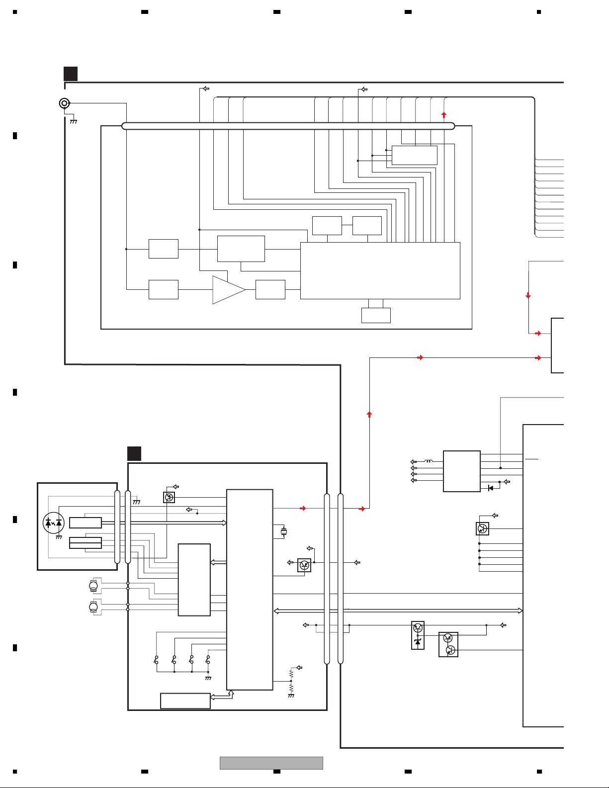
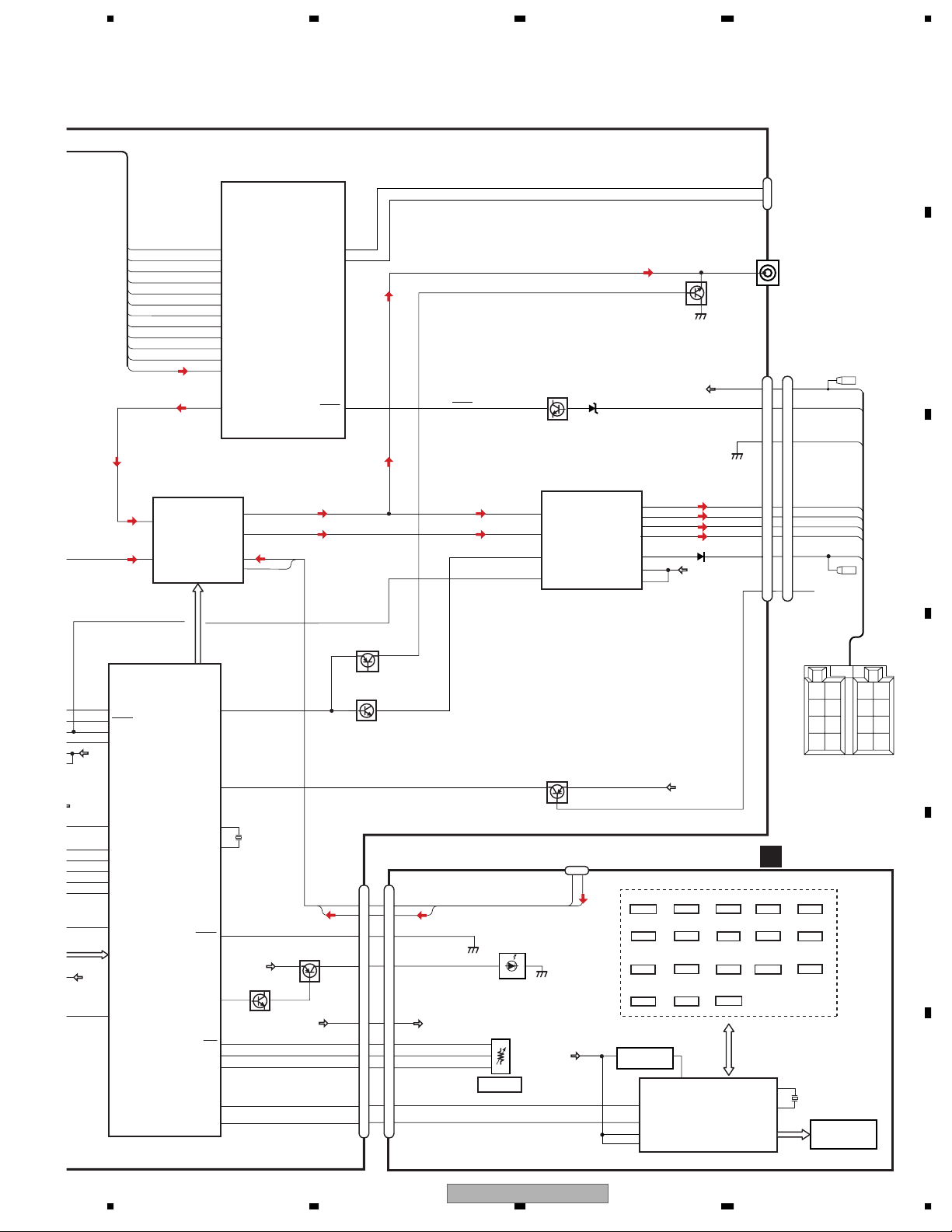
3. BLOCK DIAGRAM AND SCHEMATIC DIAGRAM
3.1 BLOCK DIAGRAM
A
B
C
ANTENNA
TUNER AMP UNIT
A
CN401
1
2
FM/AM TUNER UNIT
SYS+B
IFB
IFA
RFGND4
VCC
SLIN
SL-IN
IFOUTA
TANK
ATT
IFOUTB
DGND
LFP
AM_ANT
1 2 3 4 5 6 7 8 9 10 12131415 1617 1819 2011
ANT
RFGND1
RFGND2
RFGND3
ATT
ATT R F
REFA
REFINA
REFB
REFINB
LDET
LDET
MIX / IF / PLL
LFPVCO
VDD
SWVDD
IC1
CF
DI
CK
DO
CE1
CE2
SLOUT
DI
CK
CE1
IC2
EEPROM
DO
CE2
SLOUT
SL-IN
IFA
IFB
REFA
REFB
LDET
DI
CK
CE1
DO
CE2
SLOUT
ELE
SO
TUNL
1
IN1_
CDL
2
IN2_
SYSPW
SYSTEM
COMPU
REGULATOR IC
CD CORE UNIT(S10.5COMP2)
VREF
FOM
TOM
C
RF-AMP, CD DECODER,
LOEJ
CLCONT
CONT
MP3/WMA DECODER,
DIGITAL SERVO /
DATA PROCESSOR
141
LD
142
PD
133
REFOUT
IC201
TD,FD
PE5547A
SD,MD
22
5
LOEJ
21
43
CLCONT
9
41
CONT
8
12EJ
7
8EJ
6
DSCSNS
9
HOME
S901
HOME
CS,SK
DI,DO
LOUT
/XTAL
/PUEN
/RESET
VDSENS
XTAL
55
50
X201
16.93MHz
52
VCC
39
16
BRST,BRXEN,BSRQ
BDATA,BSCK
11
VDD
CN651
LOUT
13
3
9
7
VDD
RESET
8
8
BRST,BRXEN,BSRQ,BDATA,BSCK
VD
VD
VD
2
14
1
15
CN701
LOUT
VDD
Q102
/RESET
VD
VD
D
Q101
12
11
14
13
16
15
18
17
S905
8EJ
S-93C56BD0I-J8
VDD
REFO
AC,BD,F,E
CD
DRIVER
IC301
BA5839FP
FOM
FOP
TOP
TOM
SOP
SOM
LCOP
LCOM
S903
DSCSNS
EEPROM
IC202
CN101
LD-
15
15
MD
5
5
88
FOM
33
FOP
FOP
2
2
TOP
TOP
1
1
TOM
44
LD+
14
14
S904
12EJ
SWD5V
SWVDD
SYS+B
VDD
Q991
CD VD
5
6
7
8
Q992
BA4918-V12
D
PICKUP UNIT
(P10.5)(SERVICE)
LASER
DIODE
HOLOGRAM
UNIT
FOCUS ACT.
MONITOR
TRACKING ACT.
DIODE
LOAD/
SPINDLE
MOTOR
CARRIAGE
MOTOR
M
M
E
IC 911
5
Q601
1
2
3
4
10
9
SWVDD
B.UP
B.UP
47
36
15
85
55
57
94
121
16
126
POWEROFF
BSENS
SYSPW
1
SWVDD
DREG
9
REGC(M)
PLL_VDD
DVDD3
DVDD2
DVDD4
CDRESET
VDCONT
IC 601(
PN500
F
14
1234
DEH-3900MP/XN/EW5
SL-IN
IFA
IFB
REFA
REFB
LDET
DI
CK
CE1
DO
CE2
SLOUT
5678
A
CN871
KEYAD
2
WIRED
Q351
RL
KEYD
CN351
CN901
REMOTE
3
2
B
1
1
3
3
BACK UP
ACC
62
77
78
96
97
99
100
101
102
103
109
136
59
SLIF_INA
IF_INB
FREF_A
FREF_B
LOCK
DI
CK
CE
DO
CE2
SL
L_OUT
SYSTEM MICRO
COMPUTER
IC 601(1/2)
PN5009A
KEYAD
KEYD
ASENS
142
130
ACC SENSE
35
ASENS
Q931
B.UP
ACC
SYSPW
SWVDD
B.UP
B.UP
126
47
36
15
1
85
9
55
57
94
121
16
POWEROFF
BSENS
SYSPW
SWVDD
DREG
REGC(M)
PLL_VDD
DVDD3
DVDD2
DVDD4
CDRESET
VDCONT
ELECTRONIC VOLUME/
SOURCE SELECTOR
TUNL
1
IN1_L
CDL
2
IN2_L
SYSTEM MICRO
COMPUTER
IC 601(2/2)
PN5009A
IC 151
PML014A
VCK, VDT, VST
MUTE
TELIN
XOUT
DSENS
ILMPW
SRC
ROT1
ROT0
DPDT/SELF
KEYDT/SELF
22
B.REMOTE
KEY MATRIX
S1803 S1805
TA
S1809
4
S1815
S1820
DOWN
S1823
AUDIO
KEY DATA
FL−
10
10
FL+
12
12
RL−
9
9
RL+
11
11
6
6
TEL
8
8
KEYBOARD UNIT
B
LOUD
S1810
S1814
UP
S1817
S1821
RIGHT
22
X0
23
X1
RLIn
FLIn
MUTE
STBY
TEL IN
Q851
SWVDD
AUX IN
1
AUX G
AMP
IC 301
PAL007C
2
CN1802
AUX L
NC/BREM
VCC
REM.CON.
3
GP1UX51RK
RL−
RL+
VCC
FL+
18
20
10
56
S1801
S1804
EJECT
S1807
2
S1812
6
S1819
FUNC
IC1802
DPDT
KYDT
VLCD
VDD
21
3
5
25
6
20
B.UP
VDD
S1802
DISP
S1808
1
S1813
5
S1822
BAND
1
17
REM
LCD DRIVER/
KEY CONTROLLER
IC 1801
PD6340A
D1803-D1810
D1812-D1821
D1823-D1825
S1827
4
1
2
VOLUME
12
14
22
4
7
Rear_L
6
Front_L
4
AUX-L
IN4+_L
5
AUX-G
IN4-_L
MUTE
Q201(2/2)
MUTE
CN831
AUX-G
AUX-L
DSENS
ILM+B
SWVDD
SOURCE
ROT1
ROT0
DPDT
KYDT
Q201(1/2)
6
7
14
9
3
4
10
11
13
12
6
7
14
9
3
4
10
11
13
12
CN1801
AUX G
AUX L
DSENS
ILL+B
SRC
ROT1
ROT0
DPDT
KYDT
SWVDD
PUSH:SOURCE
44
26
82
X601
74.1MHz
81
XIN
34
ILMPW
B.UP
Q822
2
33
111
110
23
24
Q821
SWD5V
23
FL−
S1806
S1811
S1816
LEFT
S1818
X1801
5MHz
EQ
BACK
GND
3
UP
B.REM
B.
REM
ACC
LCD1801
GND
FL−
FL+
RL−
RL+
RR
RR
−
FR
FR
−
FL
−
RL
−
C
+
+
D
FL
+
RL
+
E
F
56
DEH-3900MP/XN/EW5
7
8
15
A-a
A-b
A-a
A-b
A-b
A-a
1234
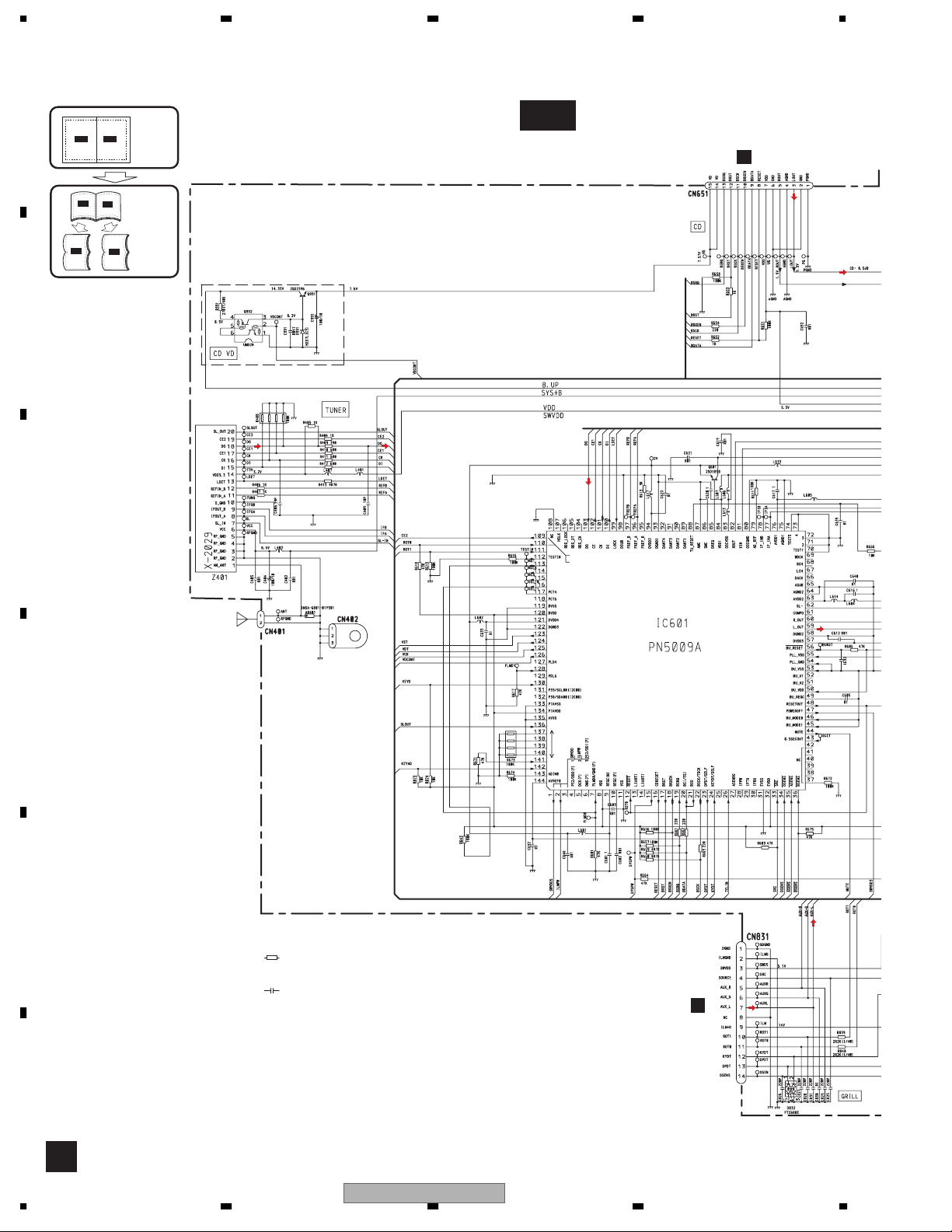
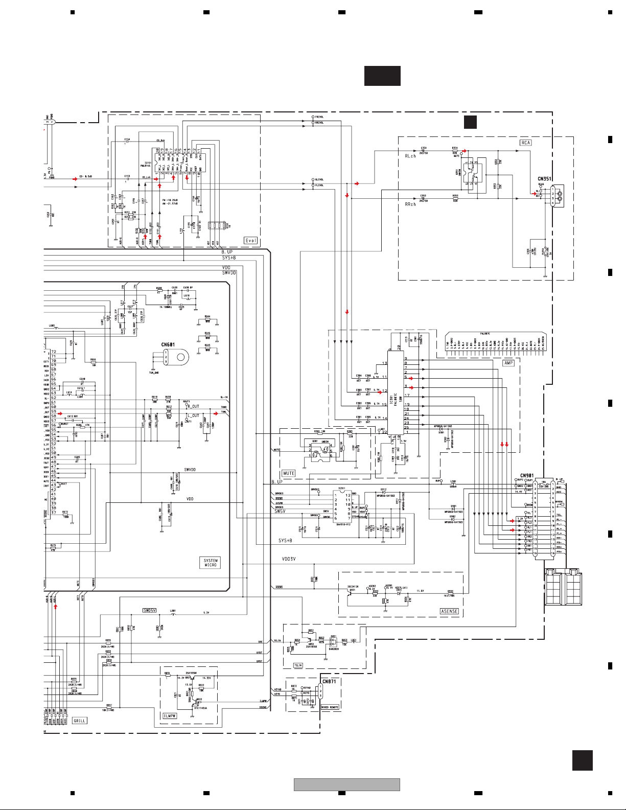
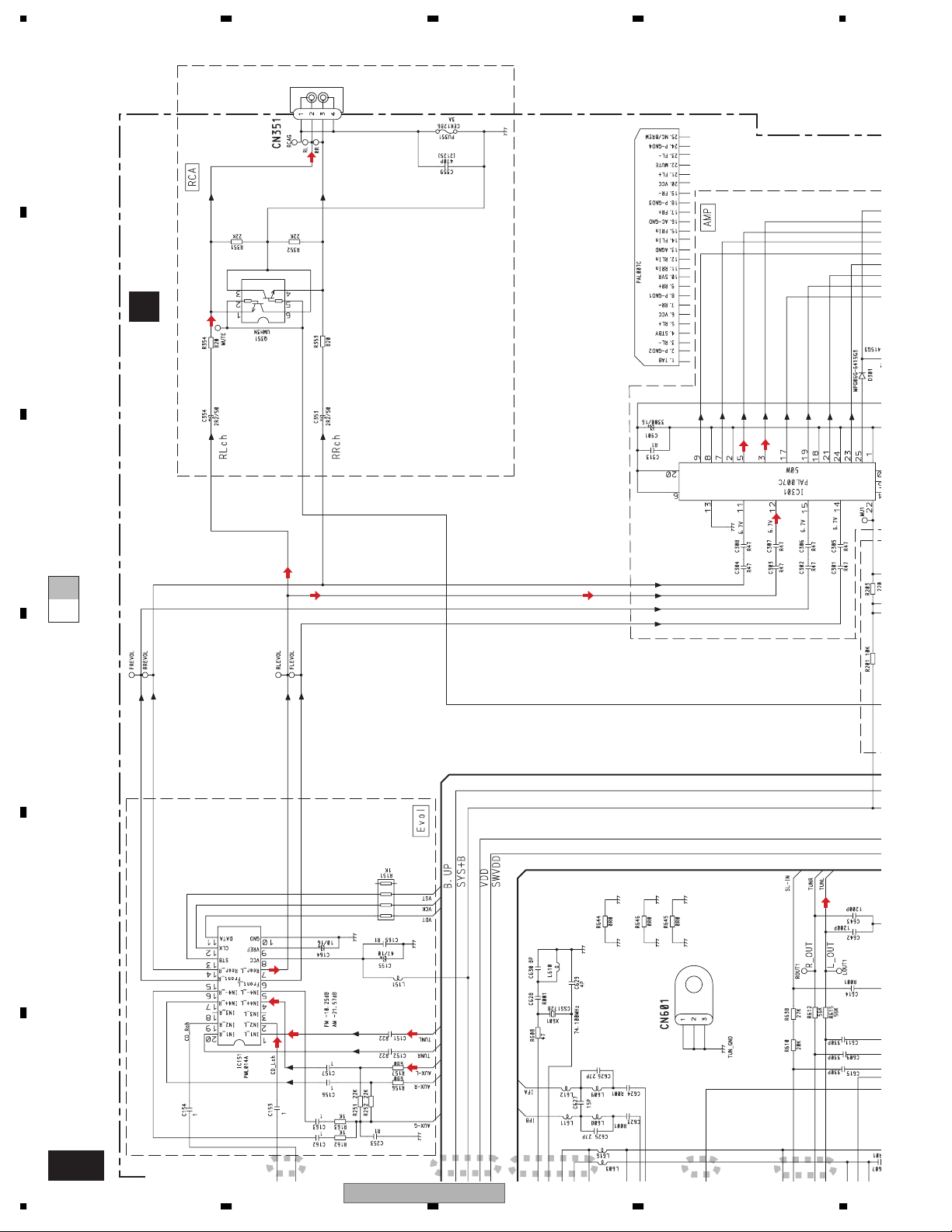
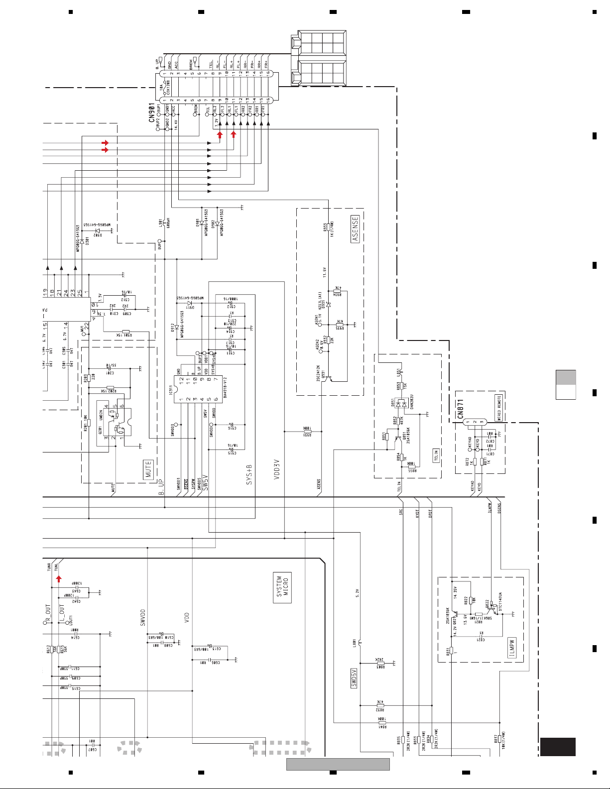
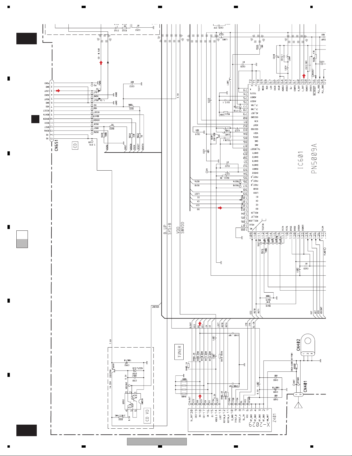
3.2 OVERALL CONNECTION DIAGRAM(GUIDE PAGE)
Note: When ordering service parts, be sure to refer to " EXPLODED VIEWS AND PARTS LIST" or
"ELECTRICAL PARTS LIST".
A
Large size
A-b
A-b
SCH diagram
Guide page
A-a
A-a
A-a
C
CN701
A-b
Detailed page
FM/AM TUNER UNIT
ROT1
ROM D ATA
ROMCK
ROMCS
SELFOUT
VST
VDT
VCK
VDCONT
FLMD1
KEYD
CE2
ROT0
SYSTEM MICRO COMPUTER
R022
A-a
B
C
D
SL
MODELAD
KEYAD
SYSPW
NC
TELIN
E
NOTE :
Symbol indicates a resistor.
No differentiation is made between chip resistors and
discrete resistors.
Symbol indicates a capacitor.
No differentiation is made between chip capacitors and
discrete capacitors.
The > mark found on some component parts indicates
the importance of the safety factor of the part.
Therefore, when replacing, be sure to use parts of
identical designation.
Decimal points for resistor
and capacitor fixed values
are expressed as :
t 2R2
2.2
0.022
t R022
B
CN1801
F
A
16
1234
DEH-3900MP/XN/EW5
5678
A-b
TUNER AMP UNIT
A
A
RCA
>
B
C
R022
>
1000/6R3
RR
RR
+
-
BACK
FR
FR
UP
+
-
B.
FL
FL
REM
+
RL
RL
ACC
GND
+
-
22K
D
E
56
DEH-3900MP/XN/EW5
F
A
7
8
17
1234
RCA
A
>
TUNER AMP UNIT
B
C
A-a A-b
D
A
E
F
A-b
18
1
DEH-3900MP/XN/EW5
1234
2
3
4
5
5
5678
+
+
+
+
RL
FL
FR
RR
-
RR
-
-
-
RL
FL
FR
B.
REM
ACC
UP
GND
BACK
A
>
B
1000/6R3
C
A-a A-b
22K
D
E
F
6
56
7
DEH-3900MP/XN/EW5
A-b
7
8
19
FLMD1
1234
A
B
C
A-b
CN701
C
1
2
3
4
5
R022
CE2
ROT0
VDCONT
VCK
VDT
VST
A-bA-a
SELFOUT
ROMCS
ROMCK
ROMDATA
ROT1
D
E
F
A-a
20
FM/AM TUNER UNIT
DEH-3900MP/XN/EW5
1234
 Loading...