

PIONEER DEH 2700 Service Manual
ORDER NO.
CRT3363
DEH-2700/XU/UC
HIGH POWER CD PLAYER WITH FM/AM TUNER
DEH-2700
This service manual should be used together with the following manual(s):
Model No. Order No. Mech.Module Remarks
CX-3110 CRT3178 S10.1 CD Mech. Module : Circuit Description, Mech. Description, Disassembly
/XU/UC
For details, refer to "Important Check Points for Good Servicing".
PIONEER CORPORATION 4-1, Meguro 1-chome, Meguro-ku, Tokyo 153-8654, Japan
PIONEER ELECTRONICS (USA) INC. P.O. Box 1760, Long Beach, CA 90801-1760, U.S.A.
PIONEER EUROPE NV Haven 1087, Keetberglaan 1, 9120 Melsele, Belgium
PIONEER ELECTRONICS ASIACENTRE PTE. LTD. 253 Alexandra Road, #04-01, Singapore 159936
PIONEER CORPORATION 2004
K-ZZA. NOV. 2004 Printed in Japan
1234
SAFETY INFORMATION
CAUTION
A
This service manual is intended for qualified service technicians; it is not meant for the casual do-it-yourselfer.
Qualified technicians have the necessary test equipment and tools, and have been trained to properly and safely repair
complex products such as those covered by this manual.
Improperly performed repairs can adversely affect the safety and reliability of the product and may void the warranty.
If you are not qualified to perform the repair of this product properly and safely, you should not risk trying to do so
and refer the repair to a qualified service technician.
W
ARNING
This product contains lead in solder and certain electrical parts contain chemicals which are known to the state of
California to cause cancer, birth defects or other reproductive harm.
B
Health & Safety Code Section 25249.6 - Proposition 65
- Service Precaution
1. You should conform to the regulations governing the product (safety, radio and noise, and other
regulations), and should keep the safety during servicing by following the safety instructions
described in this manual.
2. Before disassembling the unit, be sure to turn off the power. Unplugging and plugging the connectors
C
during power-on mode may damage the ICs inside the unit.
3. To protect the pickup unit from electrostatic discharge during servicing, take an appropriate treatment
(shorting-solder) by referring to "the DISASSEMBLY".
4. After replacing the pickup unit, be sure to check the grating.
D
E
F
2
1234
DEH-2700/XU/UC
5678
[Important Check Points for Good Servicing]
In this manual, procedures that must be performed during repairs are marked with the below symbol.
Please be sure to confirm and follow these procedures.
1. Product safety
Please conform to product regulations (such as safety and radiation regulations), and maintain a safe servicing environment by
following the safety instructions described in this manual.
1 Use specified parts for repair.
Use genuine parts. Be sure to use important parts for safety.
2 Do not perform modifications without proper instructions.
Please follow the specified safety methods when modification(addition/change of parts) is required due to interferences such as
radio/TV interference and foreign noise.
3 Make sure the soldering of repaired locations is properly performed.
When you solder while repairing, please be sure that there are no cold solder and other debris.
Soldering should be finished with the proper quantity. (Refer to the example)
4 Make sure the screws are tightly fastened.
Please be sure that all screws are fastened, and that there are no loose screws.
5 Make sure each connectors are correctly inserted.
Please be sure that all connectors are inserted, and that there are no imperfect insertion.
6 Make sure the wiring cables are set to their original state.
Please replace the wiring and cables to the original state after repairs.
In addition, be sure that there are no pinched wires, etc.
7 Make sure screws and soldering scraps do not remain inside the product.
Please check that neither solder debris nor screws remain inside the product.
8 There should be no semi-broken wires, scratches, melting, etc. on the coating of the power cord.
Damaged power cords may lead to fire accidents, so please be sure that there are no damages.
If you find a damaged power cord, please exchange it with a suitable one.
9 There should be no spark traces or similar marks on the power plug.
When spark traces or similar marks are found on the power supply plug, please check the connection and advise on secure
connections and suitable usage. Please exchange the power cord if necessary.
0 Safe environment should be secured during servicing.
When you perform repairs, please pay attention to static electricity, furniture, household articles, etc. in order to prevent injuries.
Please pay attention to your surroundings and repair safely.
A
B
C
D
2. Adjustments
To keep the original performance of the products, optimum adjustments and confirmation of characteristics within specification.
Adjustments should be performed in accordance with the procedures/instructions described in this manual.
3. Lubricants, Glues, and Replacement parts
Use grease and adhesives that are equal to the specified substance.
Make sure the proper amount is applied.
4. Cleaning
For parts that require cleaning, such as optical pickups, tape deck heads, lenses and mirrors used in projection monitors, proper
cleaning should be performed to restore their performances.
5. Shipping mode and Shipping screws
To protect products from damages or failures during transit, the shipping mode should be set or the shipping screws should be
installed before shipment. Please be sure to follow this method especially if it is specified in this manual.
56
DEH-2700/XU/UC
E
F
7
8
3

1234
CONTENTS
SAFETY INFORMATION..................................................................................................................................... 2
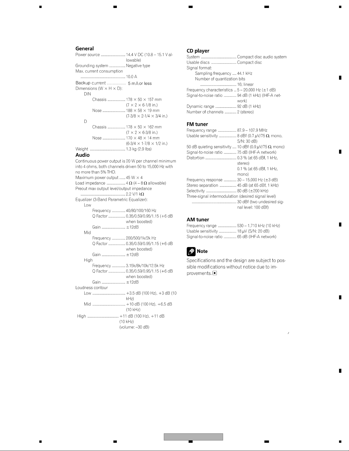
1. SPECIFICATIONS ............................................................................................................................................5
2. EXPLODED VIEWS AND PARTS LIST............................................................................................................ 6
A
B
C
2.1 PACKING................................................................................................................................................... 6
2.2 EXTERIOR................................................................................................................................................. 8
2.3 CD MECHANISM MODULE.....................................................................................................................10
3. BLOCK DIAGRAM AND SCHEMATIC DIAGRAM..........................................................................................12
3.1 BLOCK DIAGRAM...................................................................................................................................12
3.2 OVERALL CONNECTION DIAGRAM(GUIDE PAGE)..............................................................................14
3.3 KEYBOARD UNIT.................................................................................................................................... 20
3.4 CD MECHANISM MODULE.....................................................................................................................22
4. PCB CONNECTION DIAGRAM ..................................................................................................................... 26
4.1 TUNER AMP UNIT...................................................................................................................................26
4.2 KEYBOARD UNIT.................................................................................................................................... 30
4.3 CD CORE UNIT(S10) .............................................................................................................................. 32
5. ELECTRICAL PARTS LIST ............................................................................................................................ 34
6. ADJUSTMENT ...............................................................................................................................................38
6.1 CD ADJUSTMENT................................................................................................................................... 38
6.2 CHECKING THE GRATING AFTER CHANGING THE PICKUP UNIT....................................................40
6.3 ERROR MODE ........................................................................................................................................ 42
6.4 SYSTEM MICROCOMPUTER TEST PROGRAM................................................................................... 43
7. GENERAL INFORMATION.............................................................................................................................44
7.1 DIAGNOSIS.............................................................................................................................................44
7.1.1 DISASSEMBLY .....................................................................................................................................44
7.1.2 CONNECTOR FUNCTION DESCRIPTION.......................................................................................... 47
7.2 PARTS......................................................................................................................................................48
7.2.1 IC ..........................................................................................................................................................48
7.2.2 DISPLAY............................................................................................................................................... 52
7.3 OPERATIONAL FLOW CHART ...............................................................................................................53
7.4 CLEANING............................................................................................................................................... 54
8. OPERATIONS ................................................................................................................................................ 55
D
E
F
4
1234
DEH-2700/XU/UC
5678
1. SPECIFICATIONS
A
B
C
D
E
56
DEH-2700/XU/UC
F
7
8
5
N
1234
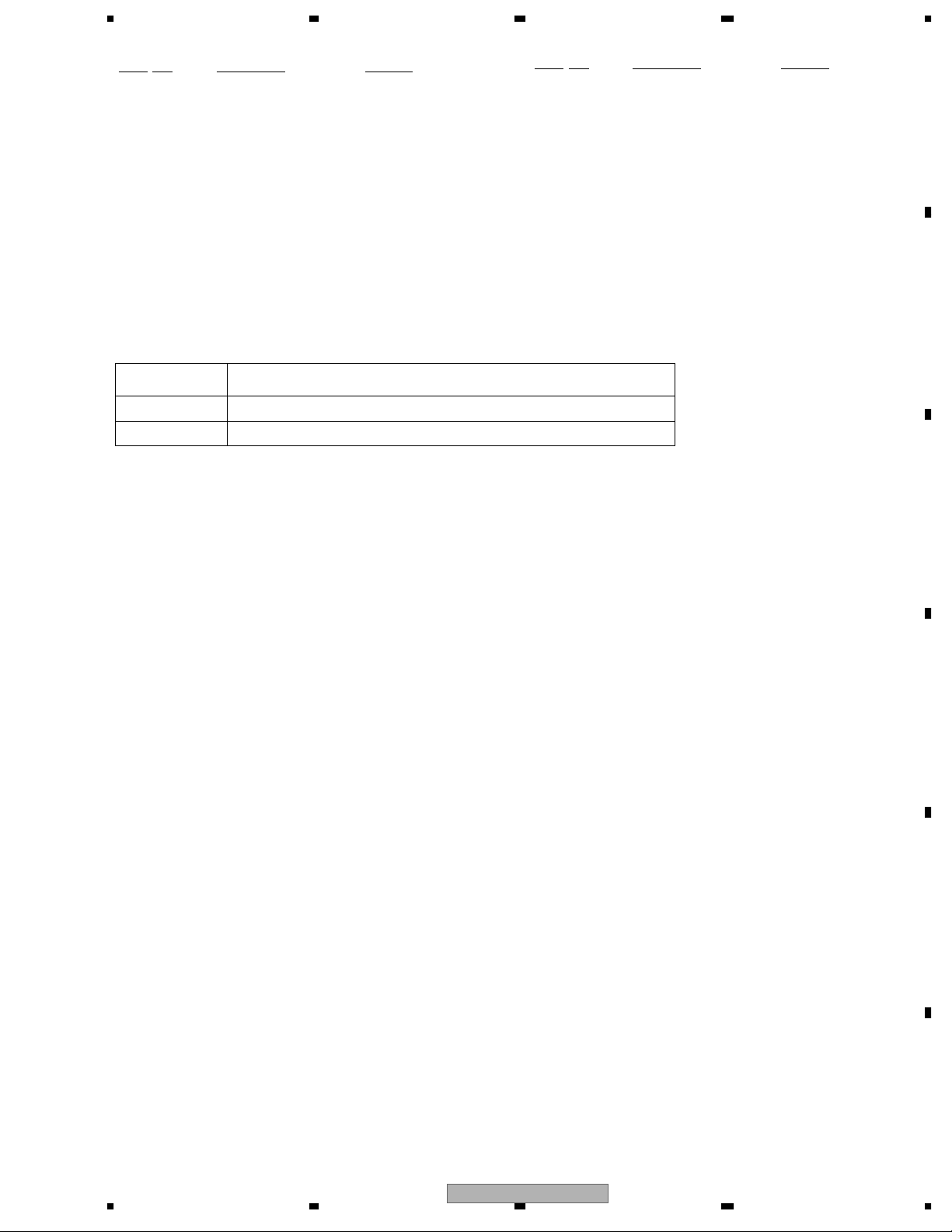
2. EXPLODED VIEWS AND PARTS LIST
OTES : • Parts marked by " * " are generally unavailable because they are not in our Master Spare Parts List.
• The > mark found on some component parts indicatesthe importance of the safety factor of the part.
A
Therefore, when replacing, be sure to use parts of identical designation.
• Screw adjacent to mark on the product are used for disassembly.
• For the applying amount of lobricants or glue, follow the instructions in this manual.
(In the case of no amount instructions,apply as you think it appropriate.)
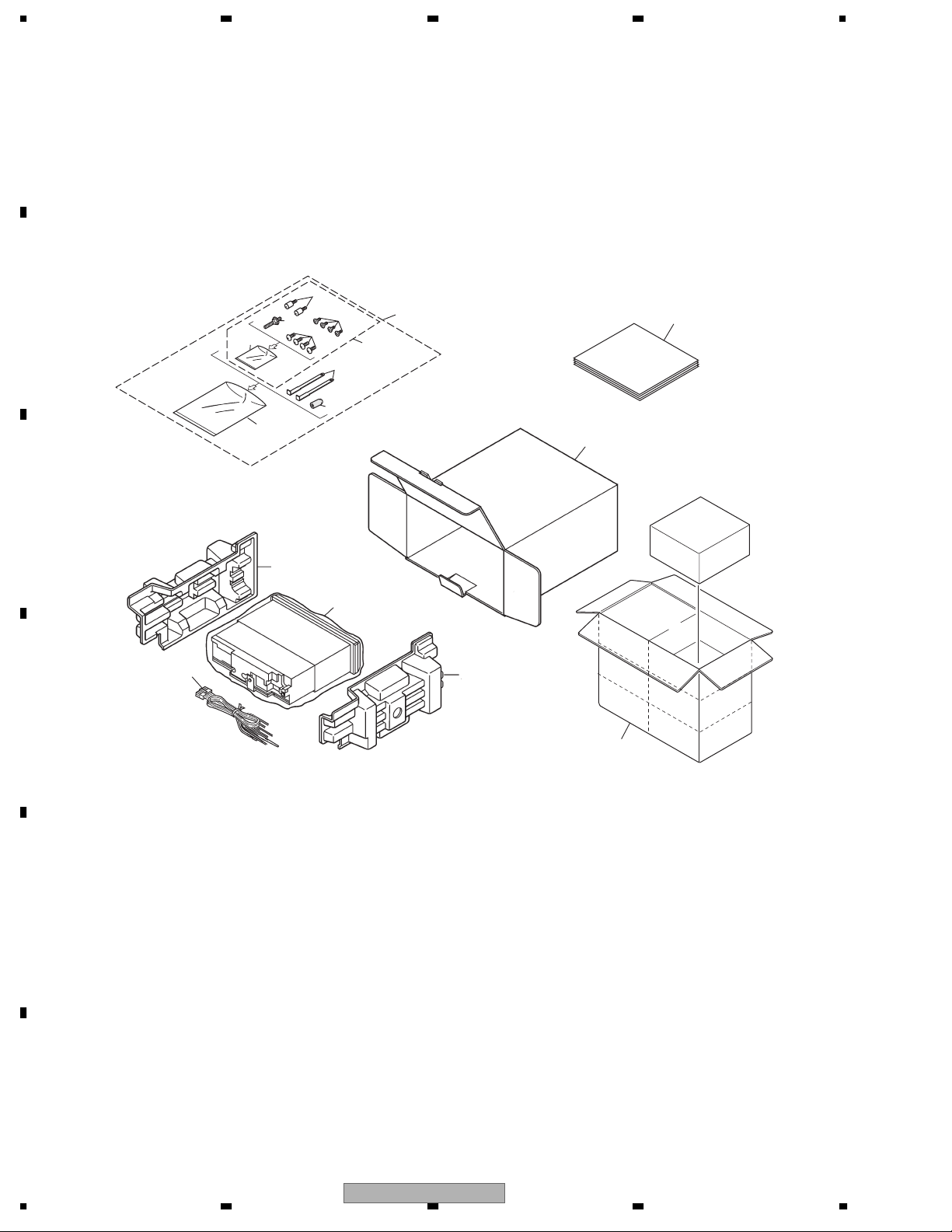
2.1 PACKING
B
"
3
4
5
8
6
7
9
10
1
2
12
16
C
14
11
17
D
E
15
13
F
6
1234
DEH-2700/XU/UC
5678
PACKING SECTION PARTS LIST
Mark No. Description Part No.
1 Accessory Assy CEA4610
2 Screw Assy CEA4611
3 Fixing Screw(M2x4) CBA1488
4 Screw CBA1650
* 5 Polyethylene Bag CEG-127
6 Screw CRZ50P090FTC
7 Screw TRZ50P080FTC
* 8 Polyethylene Bag CEG-158
9 Handle CNC5395
10 Bush CNV3930
11 Polyethylene Bag CEG1173
Owner's Manual,Installation Manual
Part No. Language
YRD5013 English, French, Spanish
YRD5017 English, French, Spanish
Mark No. Description Part No.
12 Carton YHG5028
13 Contain Box YHL5028
14 Protector XHP7004
15 Protector XHP7003
16-1 Owner's Manual YRD5013
16-2 Installation Manual YRD5017
16-3 Caution Card CRP1294
16-4 Caution Card CRP1310
* 16-5 Card ARY1048
17 Cord Assy XDE7008
A
B
C
D
E
56
DEH-2700/XU/UC
F
7
8
7

1234
2.2 EXTERIOR
58
62
57
64
63
56
59
C
65
6
18
9
8
19
70
A
60
A
13
44
31
10
31
66
65
61
65
B
52
B
42
36
35
43
53
33
C
2
2
D
12
41
39
38
34
2
2
49
47
48
37
40
32
3
68
17
68
23
17
25
50
67
46
51
27
24
B
22
A
16
30
31
45
28
20
55
31
11
1
69
21
26
29
5
14
E
B
54
F
8
1234
15
A
4
4
C
DEH-2700/XU/UC
4
7

5678
EXTERIOR SECTION PARTS LIST
Mark No. Description Part No.
1 Screw BMZ40P140FTC
2 Screw BSZ26P060FTC
3 Screw BSZ30P060FTC
4 Screw BSZ30P200FTC
5 Cable CDE7113
6 Case CNB2793
7 Holder CNC8659
8 Earth Plate CNC8915
9 Cushion CNM8890
10 Panel CNS8046
11 Holder CNV7619
12 CD Mechanism Module(S10) CXK5601
13 Cord Assy XDE7008
14 Insulator XNM7106
15 Insulator YNM5012
16 Tuner Amp Unit YWM5049
17 Screw ASZ26P060FTC
18 Screw BPZ26P080FTC
19 Screw BSZ26P160FTC
> 20 Fuse(10A) CEK1208
21 Pin Jack(CN352) CKB1057
22 Plug(CN901) CKM1376
23 Connector(CN721) CKS3835
24 Connector(CN621) CKS4124
25 Connector(CN831) CKS4944
Mark No. Description Part No.
50 Lighting Conductor YNV5004
51 Lighting Conductor YNV5005
52 Rubber Contact YNV5006
53 Grille Unit YXA5071
54 Chassis Unit YXA5080
55 Button(DETACH) CAC4836
56 Spring CBH1835
57 Spring CBH2208
58 Spring CBH2367
59 Bracket CNC6791
60 Holder CNC8042
61 Cover CNM6276
62 Arm CNV4692
63 Arm CNV4728
64 Arm CNV5576
65 Screw IMS20P030FZK
66 Panel YNS5046
67 IC(IC921) NJM2388F84
68 Transistor(Q911, 991) 2SD2396
69 IC(IC302) TDA7386
70 FM/AM Tuner Unit(Z401) CWE1646
A
B
C
26 Antenna Jack(CN401) CKX1056
27 Holder CND1328
28 Heat Sink CNR1668
29 Holder CND1054
30 Holder YNC5002
31 Screw BPZ20P100FZK
32 Spring CBH2210
33 Knob(VOLUME) YAA5001
34 Button(DETACH) YAC5027
35 Button(SOURCE) YAC5030
36 Button(1-6, LOCAL/BSM) YAC5031
37 Button(AUDIO, LOUDNESS) YAC5032
38 Button(BAND) YAC5033
39 Button(EJECT, PAUSE) YAC5034
40 Button(DOWN, RIGHT) YAC5035
41 Button(UP, LEFT) YAC5036
42 Button(CLOCK, EQ) YAC5039
43 Spring YBL5001
44 Cover YNS5038
45 Connector(CN1801) CKS4943
46 Sheet CNM7932
47 Connector CNV7369
48 LCD(LCD1801) YAW5021
49 Holder YNC5005
D
E
F
56
DEH-2700/XU/UC
7
8
9
1234
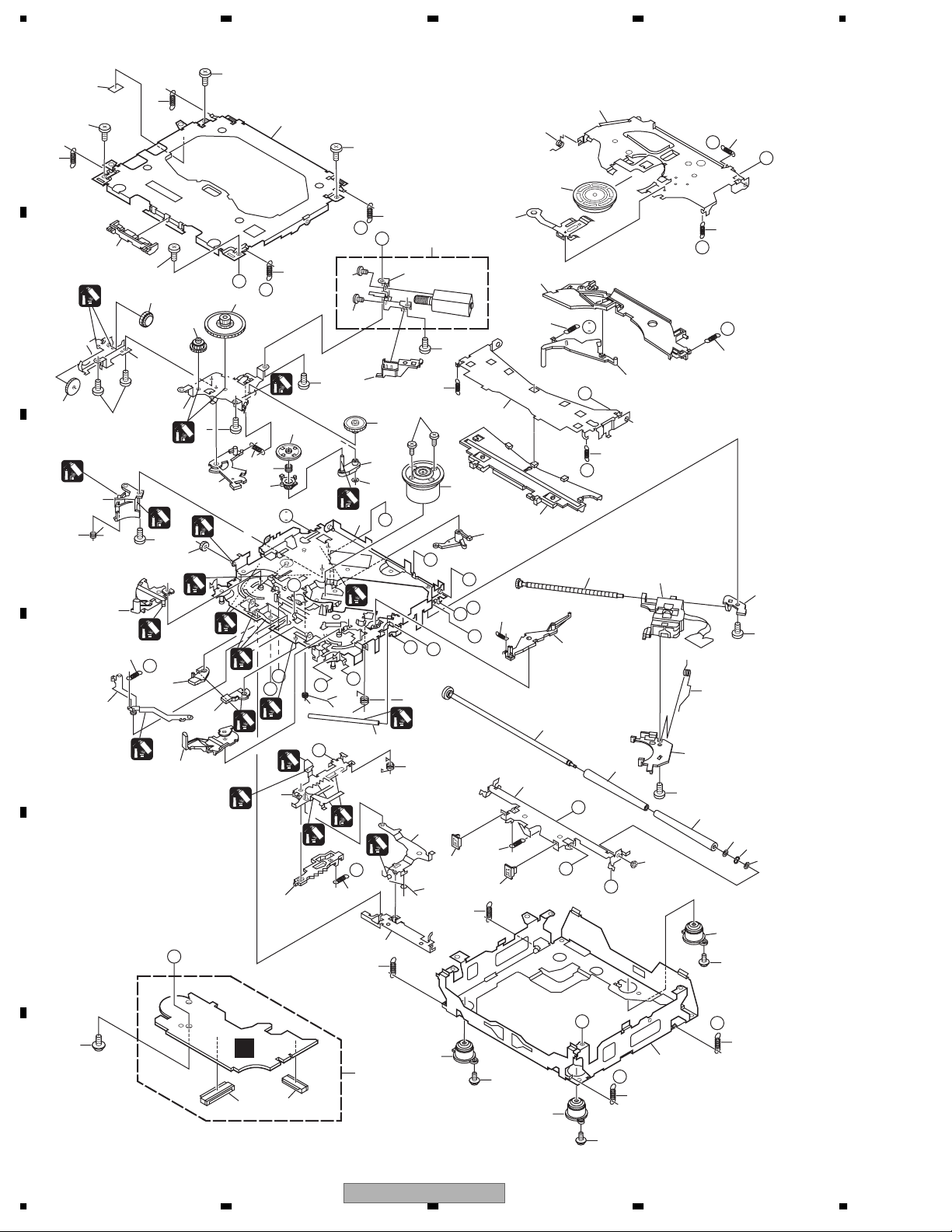
2.3 CD MECHANISM MODULE
42
A
5
13
13
5
81
34
5
15
22
E
F
93
13
A
44
B
5
B
1
54
53
C
52
13
D
86
86
82
83
4
37
71
4
29
51
1
73
50
72
10
1
I
76
B
55
5
36
4
1
18
2
64
47
C
24
2
1
7
61
2
M
1
23
87
75
E
63
57
62
58
1
G
L
1
N
R
1
1
2
1
40
56
D
O
16
P
33
1
1
P
19
J
12
3
20
39
1
69
30
2
21
M
D
79
2
1GEM1024
2GEM1045
3GEM1035
E
92
26
G
68
28
I
H
28
45
J
38
23
K
59
49
F
Q
A
27
H
77
90
48
8
67
17
78
25
70
60
80
N
L
K
43
46
6
60
11
89
10
14
74
R
31
41
85
C
91
F
C
3
65
1
2
85
66
35
O
31
Q
14
85
10
1234
DEH-2700/XU/UC

5678
CD MECHANISM MODULE SECTION PARTS LIST
Mark No. Description Part No.
1 CD Core Unit(S10) CWX3110
2 Connector(CN101) CKS4182
3 Connector(CN701) CKS4188
4 Screw BMZ20P035FTC
5 Screw BSZ20P040FTC
6 Screw(M2x4) CBA1362
7 Screw(M2x3) CBA1824
8 Screw(M2x3) CBA1825
9 •••••
10 Washer CBF1038
11 Washer CBF1060
12 Spring CBH2390
13 Spring CBH2606
14 Spring CBH2607
15 Spring CBH2608
16 Spring CBH2609
17 Spring CBH2610
18 Spring CBH2735
19 Spring CBH2612
20 Spring CBH2613
21 Spring CBH2614
22 Spring CBH2615
23 Spring CBH2616
24 Spring CBH2617
25 Spring CBH2620
26 Spring CBH2621
27 Spring CBH2641
28 Spring CBH2642
29 Spring CBH2643
30 Spring CBH2659
31 Spring CBH2688
32 •••••
33 Shaft CLA4441
34 Frame CND2443
35 Frame CNC9963
36 Bracket CND2712
37 Bracket CND1895
38 Arm CNC9968
39 Arm CND1909
40 Lever CND2032
41 Lever CNC9984
42 Sheet CNM8134
43 Collar CNV8447
44 Guide CNV8448
45 Arm CNV8403
Mark No. Description Part No.
50 Gear CNV8379
51 Gear CNV8380
52 Gear CNV8381
53 Gear CNV8382
54 Gear CNV8383
55 Gear CNV8384
56 Rack CNV8385
57 Arm CNV8386
58 Arm CNV8387
59 Guide CNV8388
60 Roller CNV8189
61 Gear CNV8389
62 Arm CNV8391
63 Arm CNV8390
64 Arm CNV8392
65 Damper CNV7313
66 Damper CNV7314
67 Arm CNV8394
68 Arm CNV8395
69 Guide CNV8396
70 Guide CNV8397
71 Holder CNV8398
72 Arm CNV8402
73 Gear CNV8400
74 Damper CNV7618
75 Motor Unit(M1) CXC4440
76 Chassis Unit CXC2318
77 Screw Unit CXB8729
78 Gear Unit CXC2397
79 Arm Unit CXC2316
80 Arm CND1896
81 Arm CND1894
82 Motor Unit(M2) CXB8933
83 Bracket CNC9985
84 •••••
85 Screw(M2x5) EBA1028
86 Screw JFZ20P020FTC
87 Screw JGZ17P022FTC
88 •••••
89 Washer YE20FTC
90 Pickup Unit(P10)(Service) CXX1647
91 Screw IMS26P030FTC
92 Spring CBL1635
93 Clamper CNV8372
A
B
C
D
E
46 Rack CNV8374
47 Holder CNV8376
48 Holder CNV8377
49 Arm CNV8378
56
DEH-2700/XU/UC
F
7
8
11
E
C
P
Q
1234
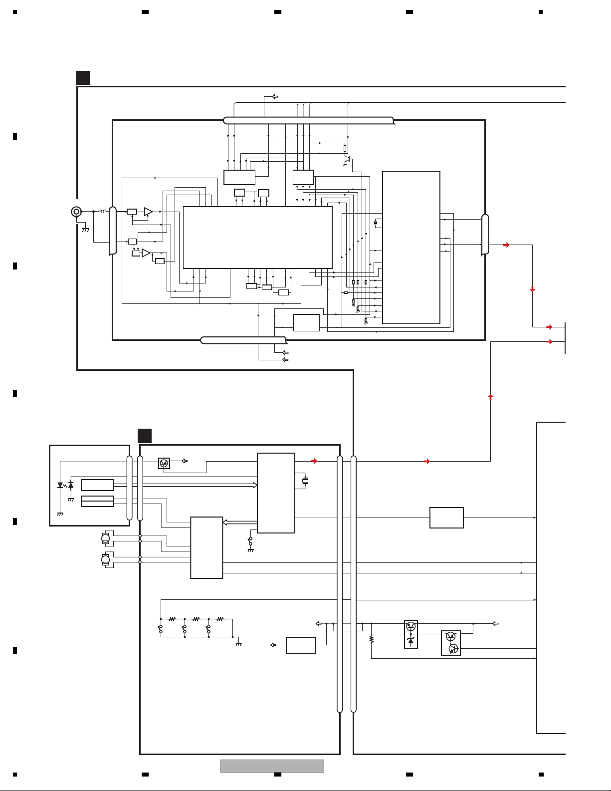
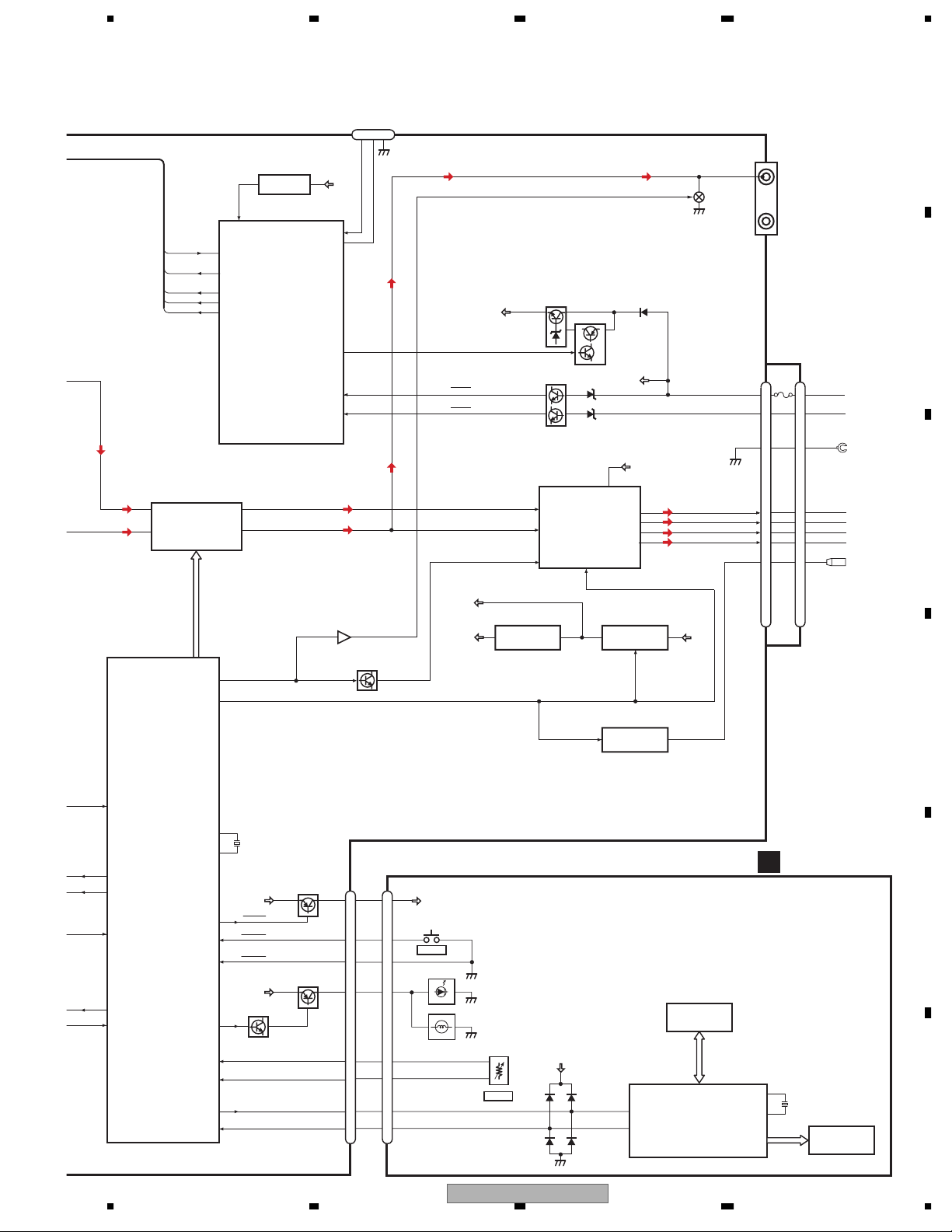
3. BLOCK DIAGRAM AND SCHEMATIC DIAGRAM
3.1 BLOCK DIAGRAM
A
B
ANTENNA
C
TUNER AMP UNIT
A
FM/AM TUNER UNIT
CN401
1
2
1
3
AM ANT
FM ANT
ATT
ATT
ANT adj
FMRF
FMRF
RF adj
VDD
76 13 5 1098 11 14 18192021
WC
CE2
ROM_VDD
IC 3 EEPROM
5.0V
OSC
LPF
IC 1
3.3V
MIXER, IF AMP
T51
CF52
RFGND
OSCGND
DGND
212 1522 16 4
AUDIOGNDNCVCC
CF51
VDD_3.3
17
SL
3.3V
5V 3.3V
3.3V 2.5V
TUN 3.3V
SYS 8V
DI
CK
NC
CE1
IC 5
←
IC 4
←
2.5V
DO
NCNCNC
NC
IC 2
2.5V
DET, FM MPX
Rch
24
Lch
23
TUN L
2
CDL
3
PICKUP UNIT
(P10)(SERVICE)
LASER
D
DIODE
MONITOR
DIODE
LOADING/
HOLOGRAM
FOCUS ACT.
TRACKING ACT.
SPINDLE
MOTOR
CARRIAGE
MOTOR
UNIT
LD+
MD
FOP
TOP
M
M
E
CD CORE UNIT(S10)
C
D
CN101
Q101
14
5
FOP
1
TOP
4
12
13
16
15
17
18
12EJ 8EJ DSCSNS
3R3V
FOP
TOP
ACT,MOTOR
DRIVER
SOP
SOM
LCOM
LCOP
IC 301
BA5835FP
LOEJ
CONT
AC, F, E, BD
FD, TD, SD, MD
22
9
HOME
1
LD
2
PD
SERVO
CONTROL,
DSP,
LPF, DAC
42
LIMIT
IC 201
UPD63712AGC
3R3V
20
LOUT
23
xtal
X201
24
XTAL
12
SO
VD
3.3V REGULATOR
3
IC 701
NJM2391DL1-33
CN701
LOUT
CONT
DSCSNS
1
LOEJ
CN721
CD L
14
8
SYSTEM
I
XSI
XSI
6
16
CDLOEJ
5
17
CONT
15
7
DSCSNS
16
6
VD
1
20
21
2
VDSENS
TC7SET08FU
Q991
42
IC 721
Q992
43
5
5
B.UP
16
29
28
79
41
78
XSI/BSI
LOEJ/NC
CONT/NC
DSCSENS
VDCONT/BRS
VDSENS
F
12
1234
DEH-2700/XU/UC
5678
TUN L
CDL
TUNPDO
11
TUNPDI
12
TUNPCK
13
CE1
56
CE2
55
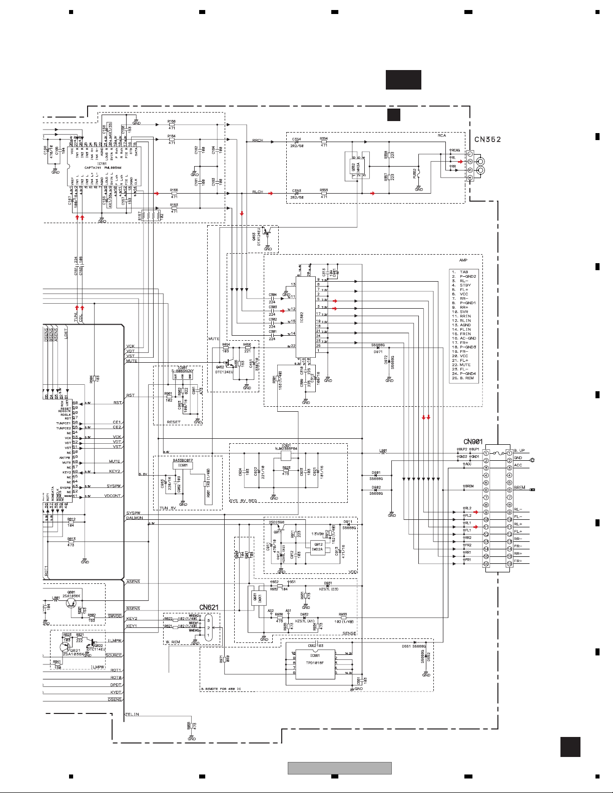
ELECTRONIC VOLUME/
SOURCE SELECTOR
2
IN1-L
IC 151
3
PML003AM
IN2-L
RESET
IC 961
S-80834CNY
60
RESET
TUNPDI
TUNPDO
TUNPCK
TUNPCE1
TUNPCE2
SYSTEM CONTROLLER
IC 601(1/2)
PE5462A
10
F Lch
11
R Lch
WIRED REMOTE CONTROL
CN621
VDD
KEY2
STRKEY
DALMON
BSENS
ASENS
123
46
80
32
64
63
BSENS
ASENS
VDD
VDD REGULATOR
Q911
BACKUP SENSE
Q931
ACC SENSE
POWER AMP
14
FLIN
RLIN
MUTE
IC 302
TDA7386
STBY
12
22
4
Q912
A
REAR OUTPUT
CN352
2
R Lch
Q352
B
B.UP
ACC
B.UP
20
23
FL-
21
FL+
3
RL-
5
RL+
CN901
B. REM
10
12
11
FUSE
1
1
10A
3
3
22
10
12
9
9
11
6
6
BACK UP
ACC
GND
FLFL+
RL-
RL+
B. REM
C
SYSTEM CONTROLLER
IC 601(2/2)
PE5462A
16
XSI/BSI
29
LOEJ/NC
28
CONT/NC
79
DSCSENS
41
VDCONT/BRSQ
78
VDSENS
VCK, VDT, VST
MUTE
SYSPW
X1
X2
SWVDD
SOURCE
DSENSE
ILMPW
ROT1
ROT0
DPDT
KYDT
48
43
70
69
21
66
65
22
36
35
9
8
X601
12.58291MHz
VDD
SWVDD
SOURCE
DSENSE
B.UP
Q822
Q801
Q821
MUTE
Q453
8V
MUTE
Q452
TU 3.3V
TUN 3V REG.
IC 981
BA33BC0FP
SYS 8V REG.
IC 921
NJM2388F84
SYSPW
B. REMOTE POWER
IC 551
TPD1018F
B.UP
SYSPW
KEYBOARD UNIT
B
D
CN1801CN831
SWVDD
3
3
SWVDD
E
SRC
4
4
DSENS
10
ILM
5
ROT1
6
ROT0
7
DPDT
8
KYDT
9
SOURCE
10
5
KEY MATRIX
IL1801
LAMP
6
7
8
9
S1827
VOLUME
SWVDD
18
DPDT
20
KYDT
KEY DATA
LCD DRIVER/
KEY CONTROLLER
IC 1801
PD6340A
21
XO
X1801
5MHz
22
XI
F
LCD1801
56
DEH-2700/XU/UC
7
8
13
1234
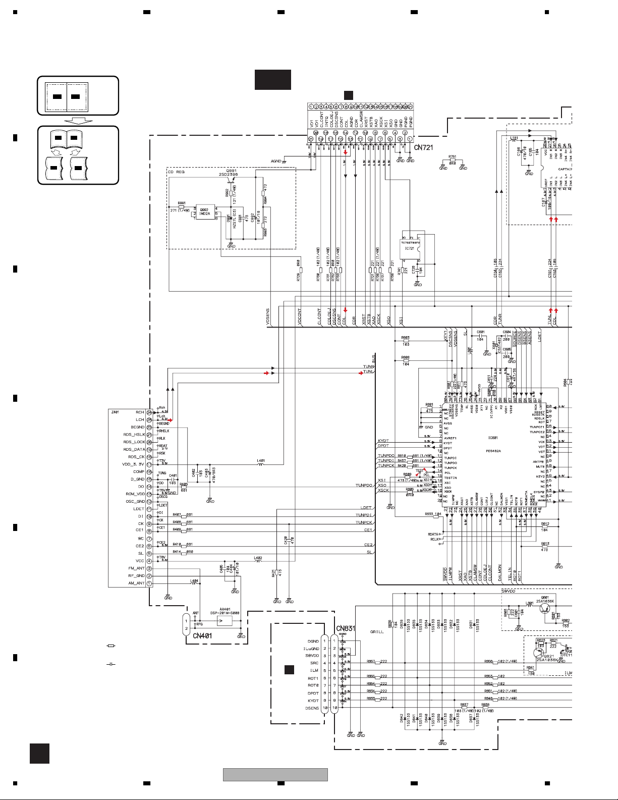
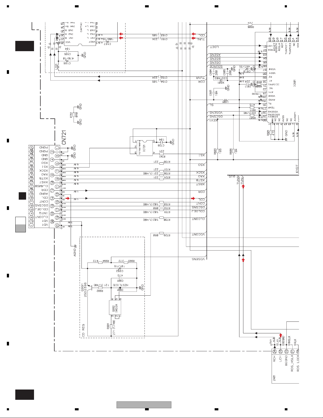
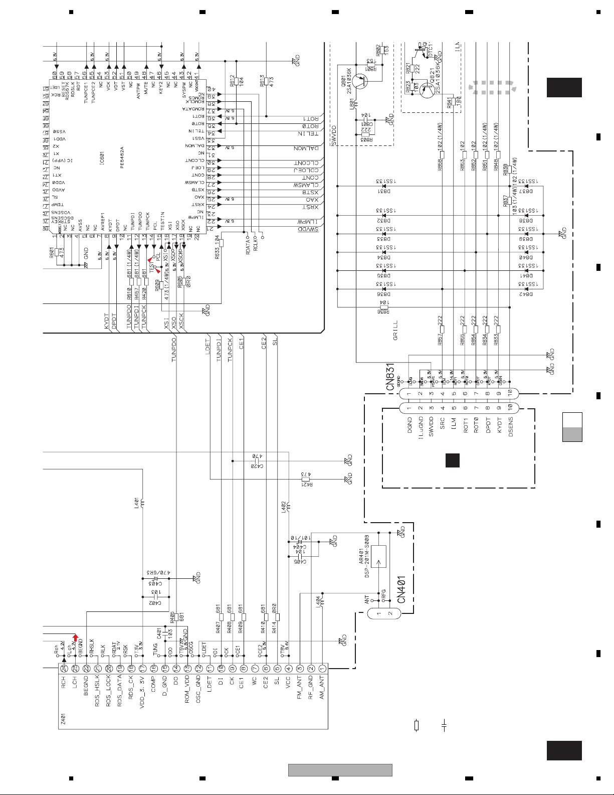
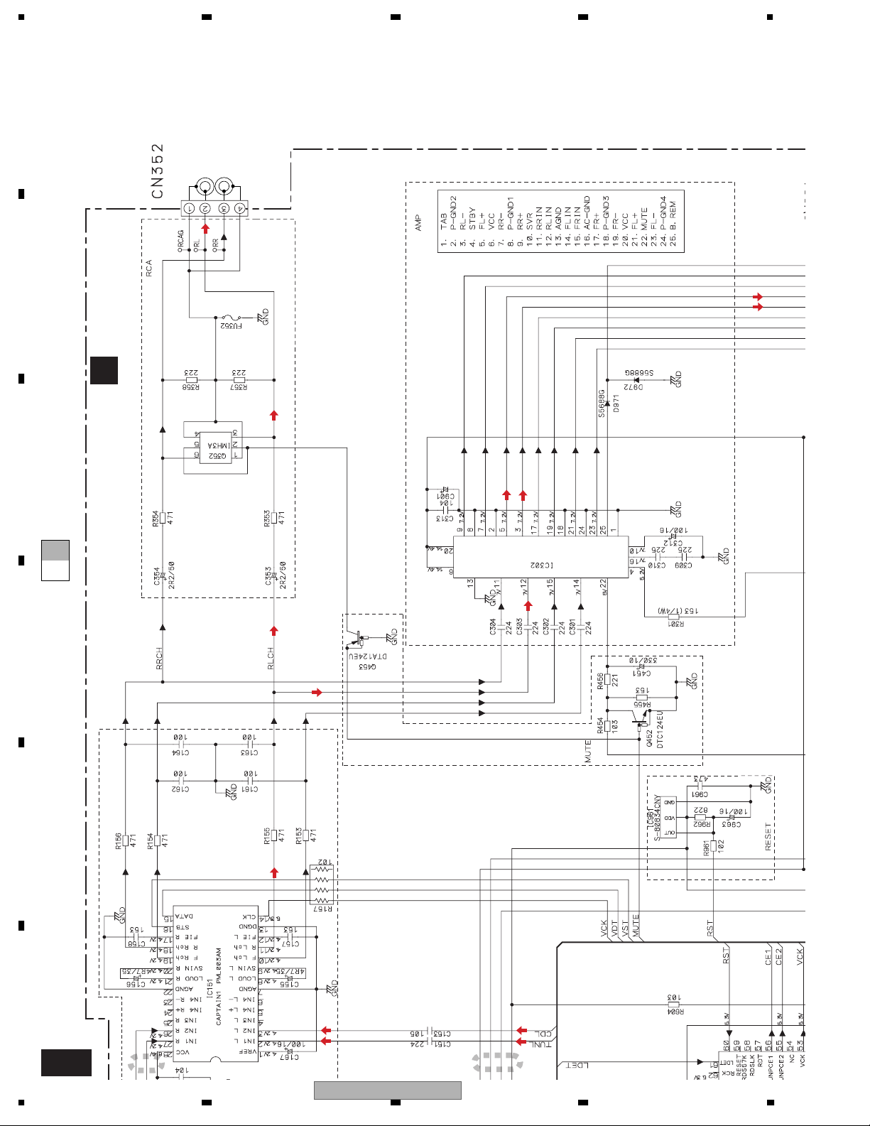
3.2 OVERALL CONNECTION DIAGRAM(GUIDE PAGE)
Note: When ordering service parts, be sure to refer to " EXPLODED VIEWS AND PARTS LIST" or
"ELECTRICAL PARTS LIST".
A
A-a
C
CN701
A-a A-b
A-a
A-b
Large size
SCH diagram
Guide page
A-b
Detailed page
E.VOL.
A-a
B
C
FM:-19.5dBs
AM: -30dBs
CD:+0.35dBs
12.58291MHz
source
SYSTEM CONTROLLER
dsens
bsens
asens
D
swvdd
FM/AM TUNER UNIT
E
ANTENNA
NOTE :
Symbol indicates a resistor.
No differentiation is made between chip resistors and
discrete resistors.
Symbol indicates a capacitor.
No differentiation is made between chip capacitors and
discrete capacitors.
For resistors and capacitors in the circuit diagrams,
their resistance values or capacitance values are expressed in codes:
Ex. *Resistors
Code Practical value
123 12k ohms
F
103 10k ohms
The > mark found on some component parts indicates
the importance of the safety factor of the part.
Therefore, when replacing, be sure to use parts of
identical designation.
*Capacitors
Code Practical value
103 0.01uF
101/10 100uF/10V
B
CN1801
A
14
1234
DEH-2700/XU/UC
source
5678
A
A-b
TUNER AMP UNIT
A
ER
E.VOL.
dsens
bsens
asens
FM: +3.6dBs
AM: -6.9dBs
CD:+10.45dBs
TDA7386(45W)
3300/16
FM: +29.6dBs
AM: +19.1dBs
CD:+36.45dBs
600µH
>
CEK1286
REAR L CH
3A
REAR R CH
B
C
CEK1208
10A
>
D
WIRED REMOTE
CONTROL
DEH-2700/XU/UC
56
E
F
A
7
8
15
A
A-b
1234
1
E.VOL.
2
asens
bsens
dsens
source
12.58291MHz
B
C
SYSTEM CONTROLLER
CN701
C
CD:+0.35dBs
A-b
A-a
A-a
D
E
F
A-a
16
FM:-19.5dBs
AM: -30dBs
DEH-2700/XU/UC
1234
FM:-19
5dBs
asens
bsens
dsens
source
5678
A
3
A-b
SYSTEM CONTROLLER
swvdd
B
CN1801
A-b
A-a
A-a
B
C
D
.
AM: -30dBs
ANTENNA
FM/AM TUNER UNIT
DEH-2700/XU/UC
56
*Capacitors
Code Practical value
103 0.01uF
101/10 100uF/10V
Symbol indicates a resistor.
No differentiation is made between chip resistors and
discrete resistors.
Symbol indicates a capacitor.
No differentiation is made between chip capacitors and
discrete capacitors.
NOTE :
7
For resistors and capacitors in the circuit diagrams,
their resistance values or capacitance values are expressed in codes:
Ex. *Resistors
Code Practical value
123 12k ohms
103 10k ohms
8
E
The > mark found on some component parts indicates
the importance of the safety factor of the part.
Therefore, when replacing, be sure to use parts of
identical designation.
F
A-a
17
1234
A
REAR L CH
REAR R CH
B
>
3A
CEK1286
TUNER AMP UNIT
A
FM: +29.6dBs
CD:+36.45dBs
AM: +19.1dBs
C
A-b
A-a
D
3300/16
TDA7386(45W)
E
F
A-b
18
FM: +3.6dBs
CD:+10.45dBs
AM: -6.9dBs
1
.
2
DEH-2700/XU/UC
1234
 Loading...