

Pioneer DEH-15, DEH-1500, DEH-5 Service manual
PIONEER CORPORATION 4-1, Meguro 1-Chome, Meguro-ku, Tokyo 153-8654, Japan
PIONEER ELECTRONICS (USA) INC. P.O.Box 1760, Long Beach, CA 90801-1760 U.S.A.
PIONEER EUROPE NV Haven 1087 Keetberglaan 1, 9120 Melsele, Belgium
PIONEER ELECTRONICS ASIACENTRE PTE.LTD. 253 Alexandra Road, #04-01, Singapore 159936
C PIONEER CORPORATION 2002
K-ZZU. NOV. 2002 Printed in Japan
ORDER NO.
CRT2968
HIGH POWER CD PLAYER WITH FM/AM TUNER
DEH-5XU/UC
DEH-5/XU/UC
- This service manual should be used together with the following manual(s):
Model No. Order No. Mech. Module Remarks
CX-3026 CRT2944 S10
CD Mech. Module:Circuit Description, Mech.Description, Disassembly
DEH-15XU/UC
For details, refer to "Important symbols for good services".
DEH-1500XU/UC
2
1
234
12
34
F
E
D
C
B
A
DEH-5/XU/UC
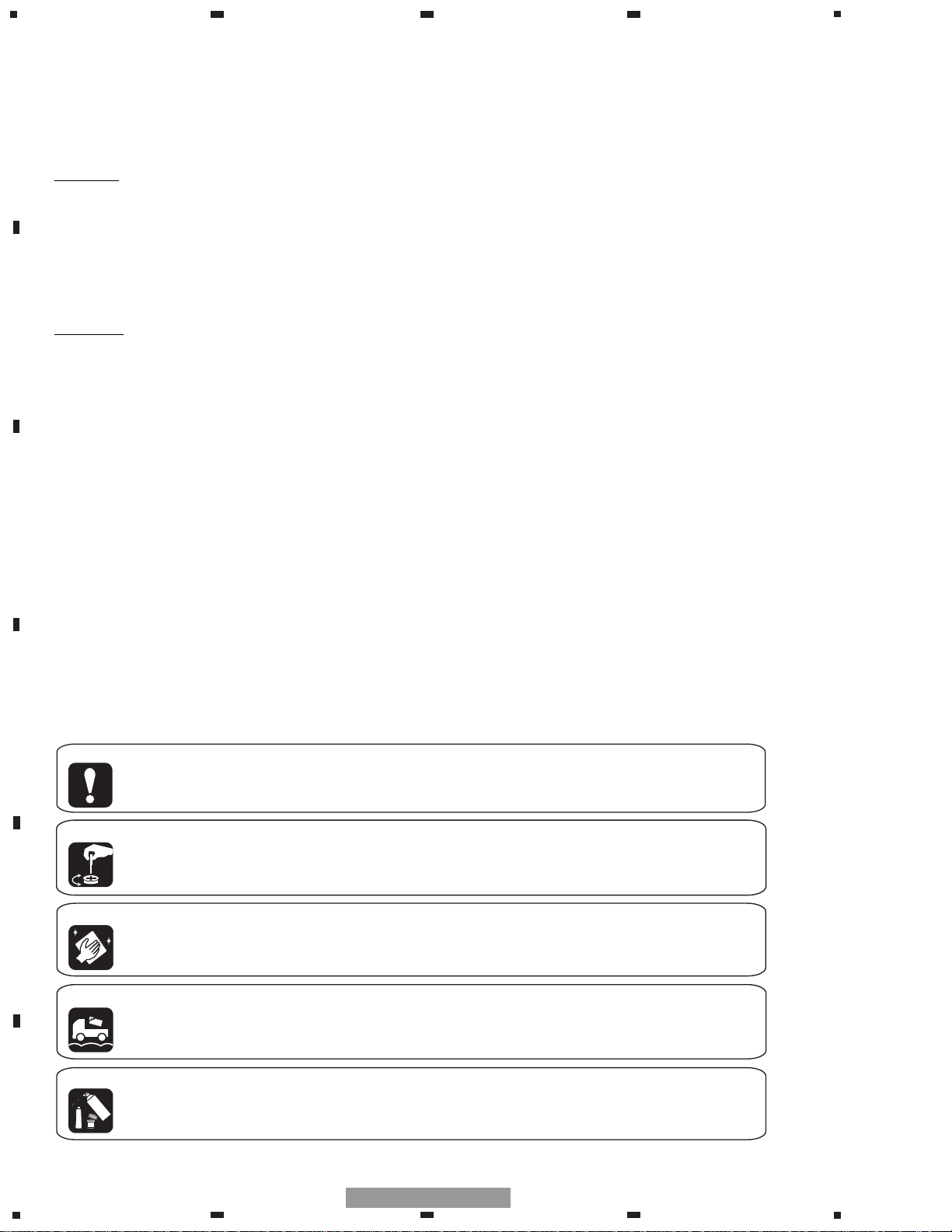
SAFETY INFORMATION
[ Important symbols for good services ]
In this manual, the symbols shown-below indicate that adjustments, settings or cleaning should be made securely.
When you find the procedures bearing any of the symbols, be sure to fulfill them:
2. Adjustments
To keep the original performances of the product, optimum adjustments or specification confirmation is indispensable.
In accordance with the procedures or instructions described in this manual, adjustments should be performed.
3. Cleaning
For optical pickups, tape-deck heads, lenses and mirrors used in projection monitors, and other parts requiring cleaning,
proper cleaning should be performed to restore their performances.
5. Lubricants, glues, and replacement parts
Appropriately applying grease or glue can maintain the product performances. But improper lubrication or applying
glue may lead to failures or troubles in the product. By following the instructions in this manual, be sure to apply the
prescribed grease or glue to proper portions by the appropriate amount.For replacement parts or tools, the prescribed
ones should be used.
4. Shipping mode and shipping screws
To protect the product from damages or failures that may be caused during transit, the shipping mode should be set or
the shipping screws should be installed before shipping out in accordance with this manual, if necessary.
1. Product safety
You should conform to the regulations governing the product (safety, radio and noise, and other regulations), and
should keep the safety during servicing by following the safety instructions described in this manual.
CAUTION
This service manual is intended for qualified service technicians; it is not meant for the casual do-it-yourselfer.
Qualified technicians have the necessary test equipment and tools, and have been trained to properly and safely repair
complex products such as those covered by this manual.
Improperly performed repairs can adversely affect the safety and reliability of the product and may void the warranty.
If you are not qualified to perform the repair of this product properly and safely, you should not risk trying to do so
and refer the repair to a qualified service technician.
W
ARNING
This product contains lead in solder and certain electrical parts contain chemicals which are known to the state of
California to cause cancer, birth defects or other reproductive harm.
Health & Safety Code Section 25249.6 - Proposition 65

3
5
6
7
8
F
E
D
C
B
A
5
6
7
8
DEH-5/XU/UC
- CD Player Service Precautions
1. Before disassembling the unit, be sure to turn off the
power. Unplugging and plugging the connectors during power-on mode may damage the ICs inside the
unit.
2. To protect the pickup unit from electrostatic discharge during serviving, take an appropriate treatment(shorting-solder) by referring to "the DISASSEMBLY" on page 47.
3. After replacing the pickup unit, be sure to check the
grating.(See p.44.)
4. In this product, because the memory capacity of the
microcomputer is insufficient, the test mode is not
installed. However grating of the pickup unit can be
confirmed.
CONTENTS
SAFETY INFORMATION............................................................................................................................................2
1. SPECIFICATIONS .......................................................................................................................................................4
2. EXPLODED VIEWS AND PARTS LIST.......................................................................................................................6
2.1 PACKING...............................................................................................................................................................6
2.2 EXTERIOR(DEH-5/XU/UC) ...................................................................................................................................8
2.3 EXTERIOR(DEH-15/XU/UC,1500/XU/UC)..........................................................................................................10
2.4 CD MECHANISM MODULE...............................................................................................................................12
3. BLOCK DIAGRAM AND SCHEMATIC DIAGRAM...................................................................................................14
3.1 BLOCK DIAGRAM ..............................................................................................................................................14
3.2 OVERALL CONNECTION DIAGRAM(GUIDE PAGE)........................................................................................18
3.3 KEYBOARD UNIT...............................................................................................................................................24
3.4 CD MECHANISM MODULE...............................................................................................................................26
4. PCB CONNECTION DIAGRAM ................................................................................................................................30
4.1 TUNER AMP UNIT .............................................................................................................................................30
4.2 KEYBOARD UNIT...............................................................................................................................................34
4.3 CD MECHANISM MODULE...............................................................................................................................36
5. ELECTRICAL PARTS LIST........................................................................................................................................38
6. ADJUSTMENT .........................................................................................................................................................43
6.1 CD ADJUSTMENT .............................................................................................................................................43
6.2 CHECKING THE GRATING AFTER CHANGING THE PICKUP UNIT................................................................44
6.3 ERROR MODE ....................................................................................................................................................46
7. GENERAL INFORMATION.......................................................................................................................................47
7.1 DIAGNOSIS ........................................................................................................................................................47
7.1.1 DISASSEMBLY ..............................................................................................................................................47
7.1.2 CONNECTOR FUNCTION DESCRIPTION....................................................................................................52
7.2 PARTS .................................................................................................................................................................53
7.2.1 IC ....................................................................................................................................................................53
7.2.2 DISPLAY.........................................................................................................................................................60
7.3 OPERATIONAL FLOW CHART...........................................................................................................................63
7.4 CLEANING..........................................................................................................................................................64
8. OPERATIONS ...........................................................................................................................................................65
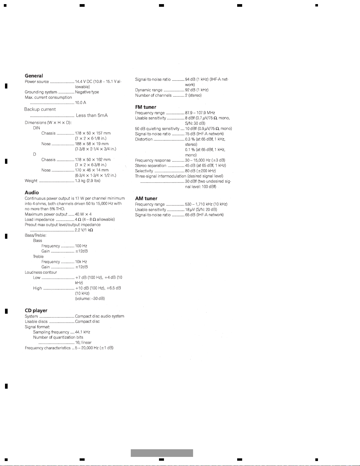
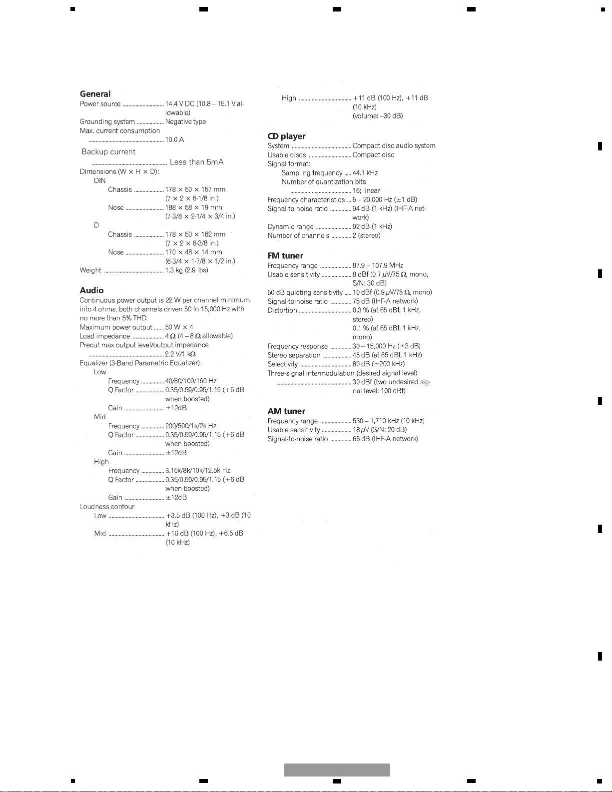
1. SPECIFICATIONS
4
1
234
12
34
F
E
D
C
B
A
DEH-5/XU/UC
- DEH-5/XU/UC
5
5
6
7
8
F
E
D
C
B
A
5
6
7
8
DEH-5/XU/UC
- DEH-15/XU/UC,DEH-1500/XU/UC
6
1
234
12
34
F
E
D
C
B
A
DEH-5/XU/UC
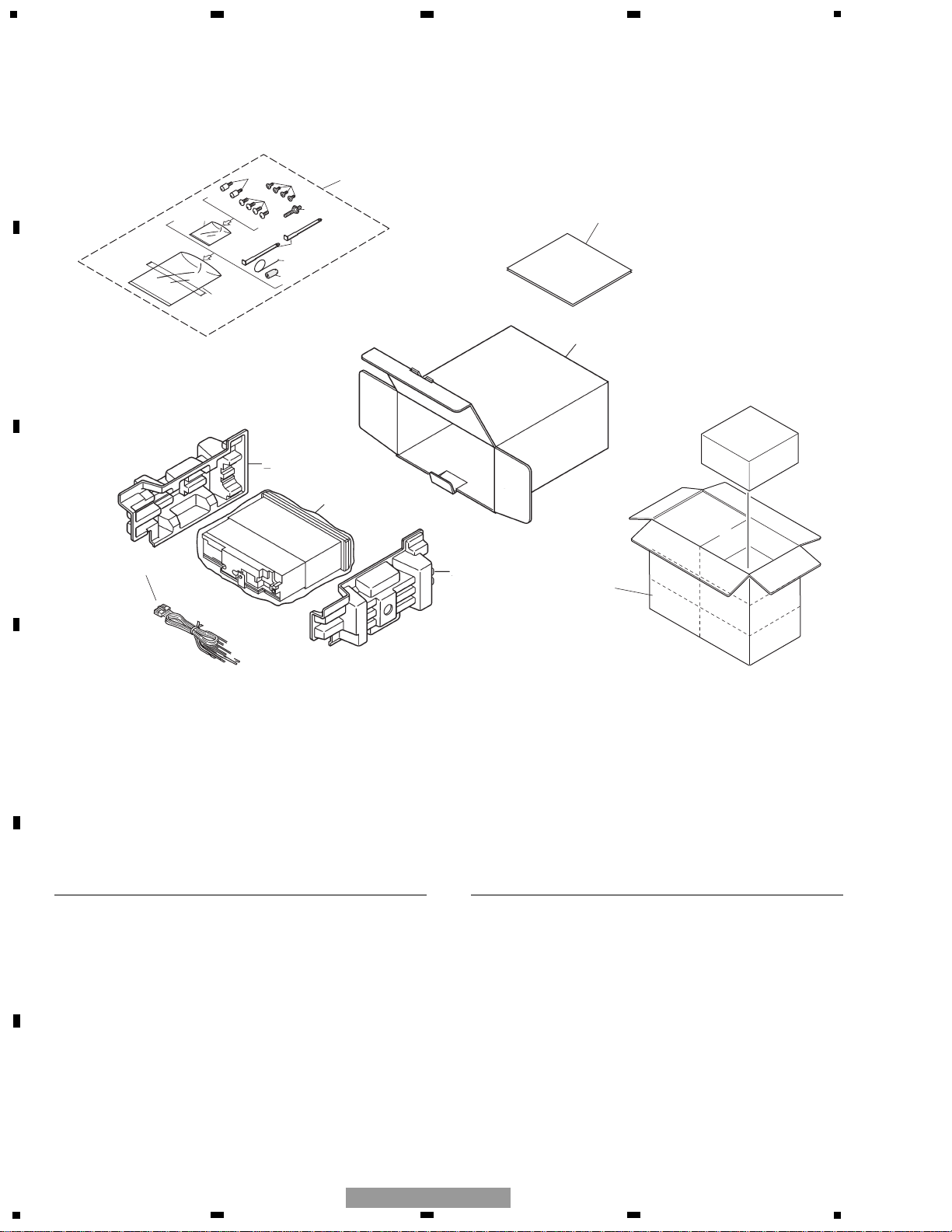
1 Cord Assy CDE7060
2 Spring CBH1650
3 Screw CBA1002
* 4 Polyethylene Bag CEG-127
5 Screw CRZ50P090FTC
6 Screw TRZ50P080FTC
* 7 Polyethylene Bag CEG-158
8 Handle CNC5395
9 Bush CNV3930
10 Polyethylene Bag CEG1173
11-1 Owner’s Manual
See Contrast table(2)
11-2 Installation Manual
See Contrast table(2)
* 11-3 Card ARY1048
11-4 Caution Card
See Contrast table(2)
12 Carton
See Contrast table(2)
13 Contain Box
See Contrast table(2)
14 Protector CHP2663
15 Protector CHP2664
16 Fixing Screw(M2x4)
See Contrast table(2)
17 Accessory Assy CEA3438
Mark No. Description Part No. Mark No. Description Part No.
(1) PACKING SECTION PARTS LIST
NOTE:
- Parts marked by “*” are generally unavailable because they are not in our Master Spare Parts List.
- Screws adjacent to ∇ mark on the product are used for disassembly.
- For the applying amount of lubricants or glue, follow the instructions in this manual.
(In the case of no amount instructions, apply as you think it appropriate.)
14
1
10
12
13
15
17
5
9
2
8
7
6
4
3
16
11
2. EXPLODED VIEWS AND PARTS LIST
2.1 PACKING
7
5
6
7
8
F
E
D
C
B
A
5
6
7
8
DEH-5/XU/UC
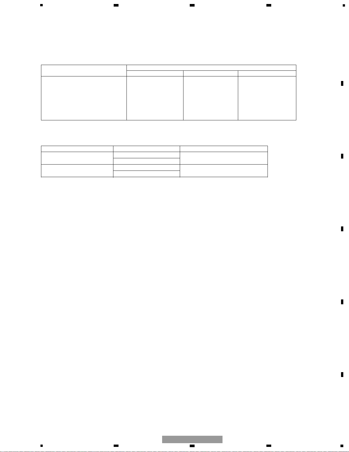
- Owner's Manual, Installation Manual
Model Part No. Language
DEH-5/XU/UC CRD3666 English,French,Spanish
CRD3667
DEH-15/XU/UC CRD3664 English,French,Spanish
DEH-1500/XU/UC CRD3665
Part No.
Mark No. Symbol and Description DEH-5/XU/UC DEH-15/XU/UC DEH-1500/XU/UC
11-1 Owner's Manual CRD3666 CRD3664 CRD3664
11-2 Installation Manual CRD3667 CRD3665 CRD3665
11-4 Caution Card Not used CRP1294 Not used
12 Catron CHG4989 CHG4988 CHG4987
13 Contain Box CHL4989 CHL4988 CHL4987
16 Fixing Screw(M2x4) Not used CBA1488 CBA1488
(2) CONTRAST TABLE
DEH-5/XU/UC , DEH-15/XU/UC and DEH-1500/XU/UC are constructed the same except for the following:
8
1
234
12
34
F
E
D
C
B
A
DEH-5/XU/UC
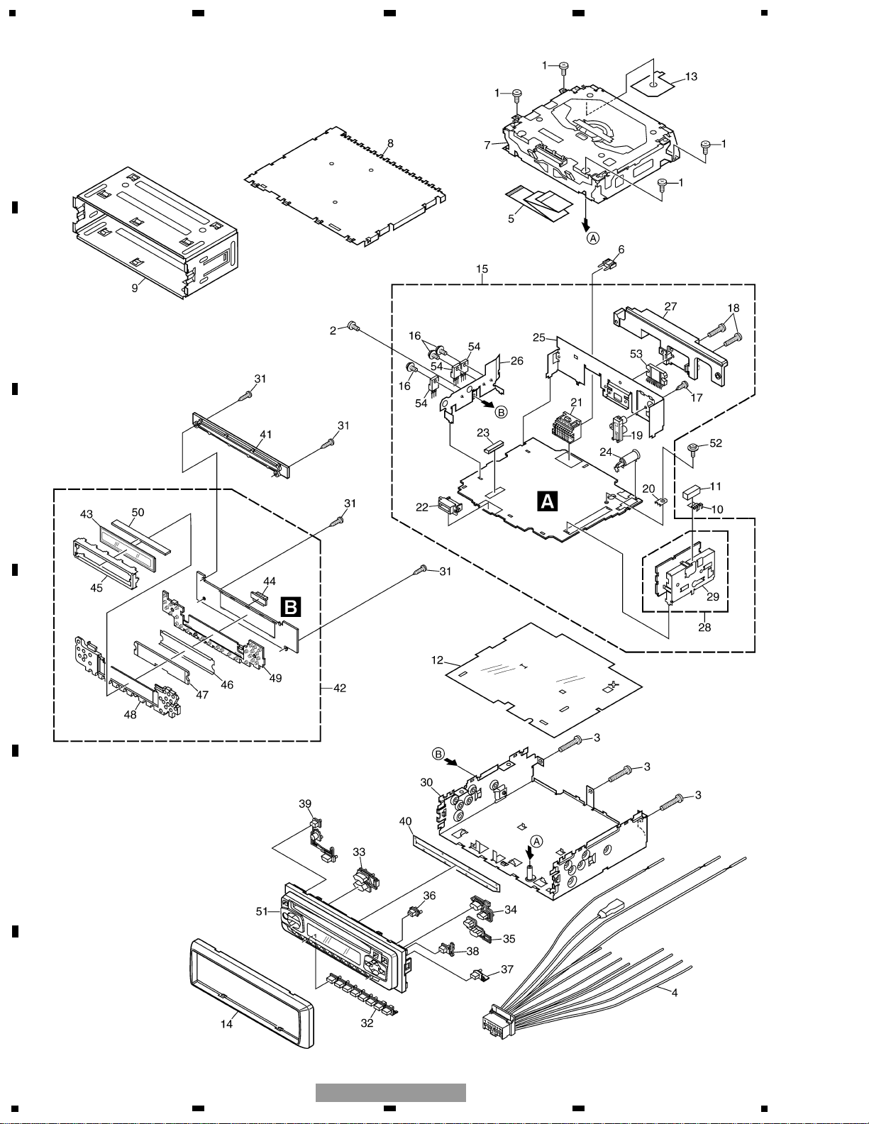
2.2 EXTERIOR(DEH-5/XU/UC)

9
5
6
7
8
F
E
D
C
B
A
5
6
7
8
DEH-5/XU/UC
1 Screw BSZ26P060FTC
2 Screw BSZ30P060FTC
3 Screw BSZ30P200FTC
4 Cord Assy CDE7060
5 Cable CDE7113
6 Fuse(10A) CEK1208
7 CD Mechanism Module(S10) CXK5600
8 Case CNB2793
9 Holder CNC8659
10 Earth Plate CNC8915
11 Cushion CNM8275
12 Insulator CNM8059
13 Insulator CNM8174
14 Panel CNS7239
15 Tuner Amp Unit CWM8569
16 Screw ASZ26P060FTC
17 Screw BPZ26P080FTC
18 Screw BSZ26P160FTC
19 Pin Jack(CN352) CKB1028
20 Terminal(CN402) CKF1059
21 Plug(CN901) CKM1376
22 Connector(CN831) CKS3581
23 Connector(CN651) CKS3835
24 Antenna Jack(CN401) CKX1056
25 Holder CND1241
26 Holder CND1328
27 Heat Sink CNR1668
28 FM/AM Tuner Unit CWE1646
29 Holder CND1054
30 Chassis Unit CXB9542
31 Screw BPZ20P080FTC
32 Button(1-6) CAC7739
33 Button(Volume) CAC7740
34 Button(Up) CAC7741
35 Button(Down) CAC7742
36 Button(Eject) CAC7743
37 Button(Audio) CAC7745
38 Button(Band) CAC7746
39 Button(SRC-EQ) CAC7841
40 Cover CNM7500
41 Holder CNV6867
42 Keyboard Unit CWM8577
43 LCD(LCD1801) CAW1756
44 Connector(CN1801) CKS3580
45 Holder CNC9617
46 Sheet CNM7932
47 Lens CNV7060
48 Lighting Conductor CNV7367
49 Rubber CNV7368
50 Connector CNV7369
51 Grille Unit CXB9805
52 Screw ISS26P055FTC
53 IC(IC302) TDA7384
54 Transistor(Q911,921,991) 2SD2375
Mark No. Description Part No. Mark No. Description Part No.
- EXTERIOR(DEH-5/XU/UC) SECTION PARTS LIST
10
1
234
12
34
F
E
D
C
B
A
DEH-5/XU/UC
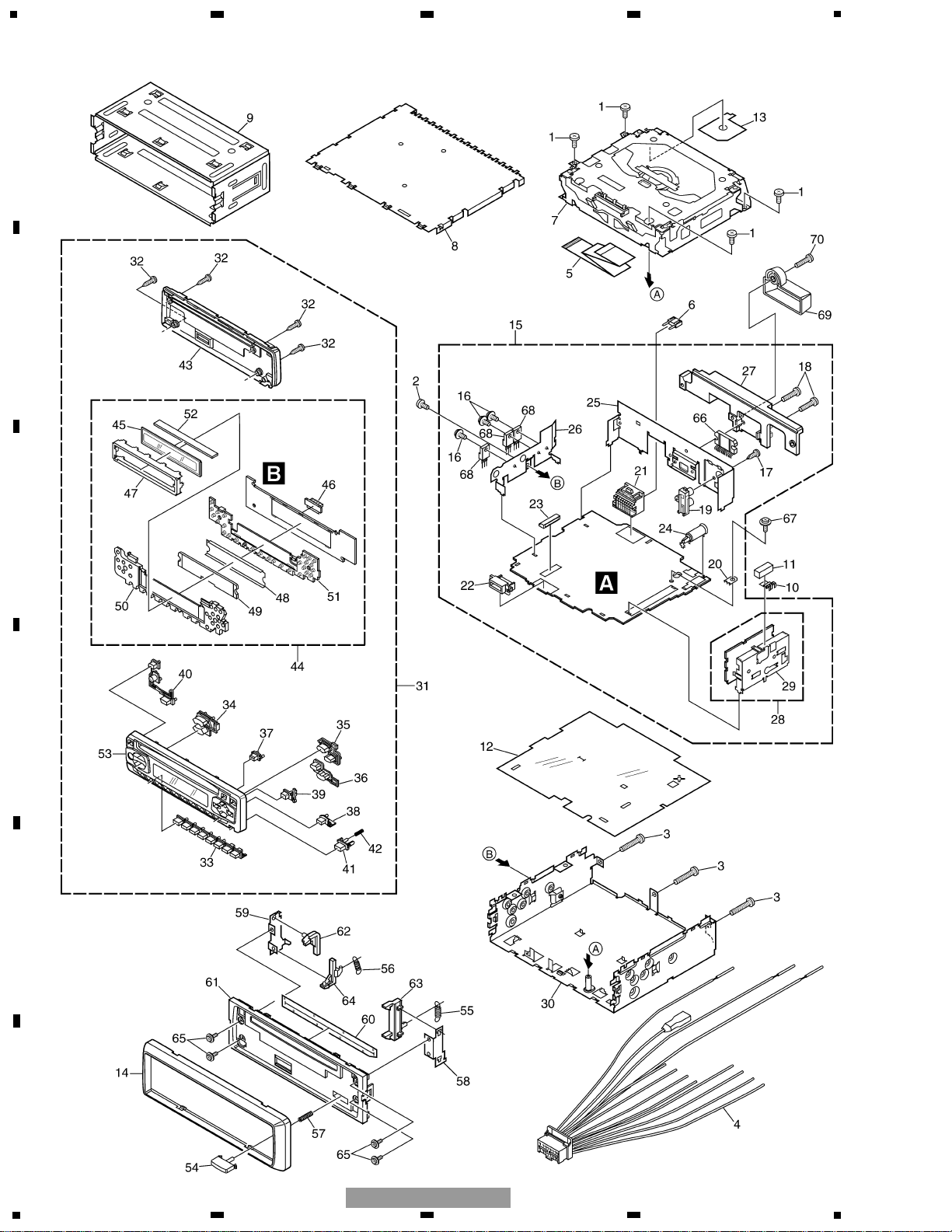
2.3 EXTERIOR(DEH-15/XU/UC,1500/XU/UC)

11
5
6
7
8
F
E
D
C
B
A
5
6
7
8
DEH-5/XU/UC
1 Screw BSZ26P060FTC
2 Screw BSZ30P060FTC
3 Screw BSZ30P200FTC
4 Cord Assy CDE7060
5 Cable CDE7113
6 Fuse(10A) CEK1208
7 CD Mechanism Module(S10) CXK5600
8 Case CNB2793
9 Holder CNC8659
10 Earth Plate CNC8915
11 Cushion CNM8275
12 Insulator CNM8059
13 Insulator CNM8174
14 Panel CNS7239
15 Tuner Amp Unit(DEH-15) CWM8568
Tuner Amp Unit(DEH-1500) CWM8794
16 Screw ASZ26P060FTC
17 Screw BPZ26P080FTC
18 Screw BSZ26P160FTC
19 Pin Jack(CN352) CKB1028
20 Terminal(CN402) CKF1059
21 Plug(CN901) CKM1376
22 Connector(CN831) CKS3581
23 Connector(CN651) CKS3835
24 Antenna Jack(CN401) CKX1056
25 Holder CND1241
26 Holder CND1328
27 Heat Sink CNR1668
28 FM/AM Tuner Unit CWE1646
29 Holder CND1054
30 Chassis Unit CXB9542
31 Detach Grille Assy(DEH-15) CXB9571
Detach Grille Assy(DEH-1500) CXC1127
32 Screw BPZ20P100FZK
33 Button(1-6) CAC7739
34 Button(Volume) CAC7740
35 Button(Up) CAC7741
36 Button(Down) CAC7742
37 Button(Eject) CAC7743
38 Button(Band) CAC7745
39 Button(Audio) CAC7746
40 Button(SRC-EQ) CAC7749
41 Button(Detach) CAC7753
42 Spring CBH2210
43 Cover CNS7232
44 Keyboard Unit(DEH-15) CWM8576
Keyboard Unit(DEH-1500)CWM8795
45 LCD(LCD1801)(DEH-15) CAW1765
LCD(LCD1801)(DEH-1500) CAW1733
46 Connector(CN1801) CKS3580
47 Holder CNC9617
48 Sheet CNM7932
49 Lens CNV7060
50 Lighting Conductor CNV7367
51 Rubber CNV7368
52 Connector CNV7369
53 Grille Unit(DEH-15) CXB9870
Grille Unit(DEH-1500) CXB9869
54 Button CAC4836
55 Spring CBH1835
56 Spring CBH2208
57 Spring CBH2367
58 Bracket CNC6791
59 Holder CNC8042
60 Cover CNM6276
61 Panel CNS7238
62 Arm CNV4692
63 Arm CNV4728
64 Arm CNV5576
65 Screw IMS20P030FZK
66 IC(IC302) PAL007A
67 Screw ISS26P055FTC
68 Transistor(Q911,921,991) 2SD1275
69 Holder(DEH-15) CNV7619
70 Screw(DEH-15) BMZ40P140FTC
Mark No. Description Part No. Mark No. Description Part No.
- EXTERIOR(DEH-15/XU/UC, 1500/XU/UC) SECTION PARTS LIST
12
1
234
12
34
F
E
D
C
B
A
DEH-5/XU/UC
C
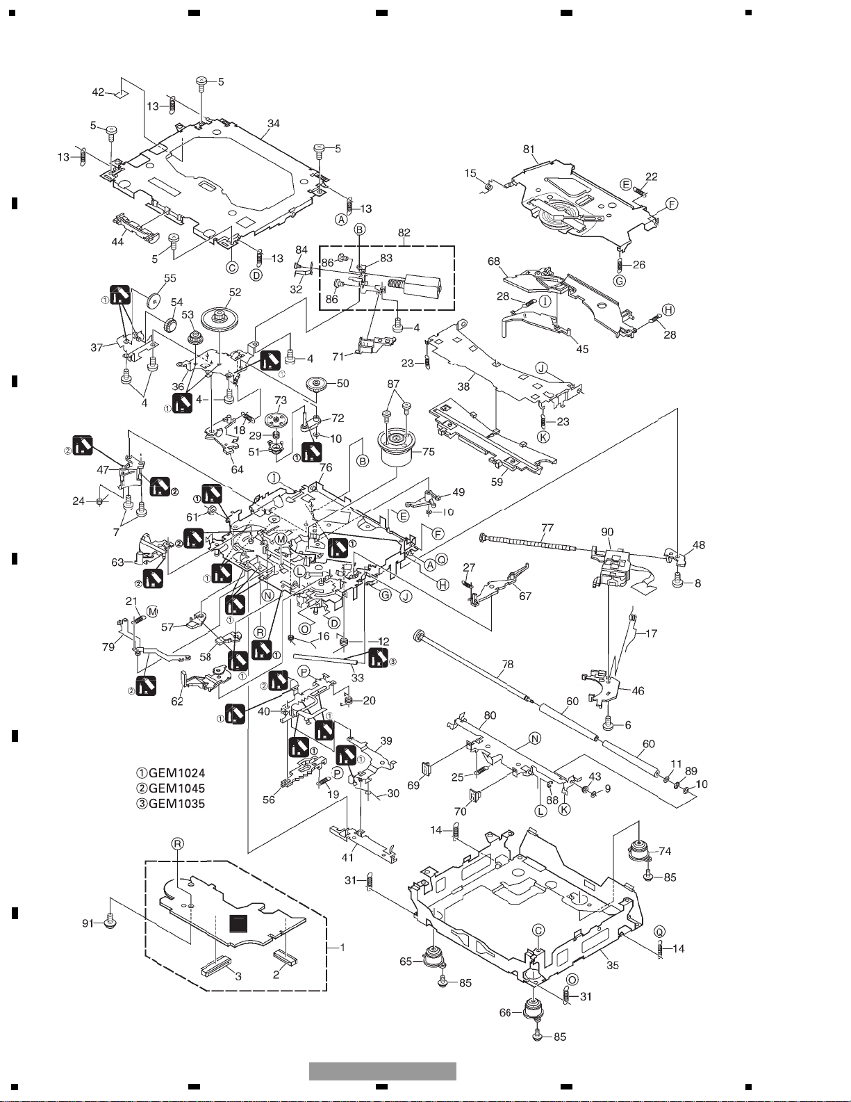
2.4 CD MECHANISM MODULE

5
6
7
8
F
E
D
C
B
A
5
6
7
8
DEH-5/XU/UC
13
Mark No. Description Part No. Mark No. Description Part No.
1 CD Core Unit(S10) CWX2708
2 Connector(CN101) CKS4182
3 Connector(CN701) CKS4188
4 Screw BMZ20P035FTC
5 Screw BSZ20P040FTC
6 Screw(M2x4) CBA1362
7 Screw(M2x3) CBA1511
8 Screw(M2x3) CBA1527
9 Washer CBF1037
10 Washer CBF1038
11 Washer CBF1060
12 Spring CBH2390
13 Spring CBH2606
14 Spring CBH2607
15 Spring CBH2608
16 Spring CBH2609
17 Spring CBH2610
18 Spring CBH2611
19 Spring CBH2612
20 Spring CBH2613
21 Spring CBH2614
22 Spring CBH2615
23 Spring CBH2616
24 Spring CBH2617
25 Spring CBH2620
26 Spring CBH2621
27 Spring CBH2641
28 Spring CBH2642
29 Spring CBH2643
30 Spring CBH2659
31 Spring CBH2688
* 32 Spring CBL1614
33 Shaft CLA3845
34 Frame CNC9962
35 Frame CNC9963
36 Bracket CNC9966
37 Bracket CNC9967
38 Arm CNC9968
39 Arm CNC9973
40 Lever CNC9983
41 Lever CNC9984
42 Sheet CNM8134
43 Collar CNV6906
44 Guide CNV6925
45 Arm CNV7198
46 Rack CNV7199
47 Holder CNV7201
48 Holder CNV7202
49 Arm CNV7203
50 Gear CNV7207
51 Gear CNV7208
52 Gear CNV7209
53 Gear CNV7210
54 Gear CNV7211
55 Gear CNV7212
56 Rack CNV7214
57 Arm CNV7215
58 Arm CNV7216
59 Guide CNV7217
60 Roller CNV7218
61 Gear CNV7219
62 Arm CNV7221
63 Arm CNV7220
64 Arm CNV7222
65 Damper CNV7313
66 Damper CNV7314
67 Arm CNV7341
68 Arm CNV7342
69 Guide CNV7360
70 Guide CNV7361
71 Holder CNV7437
72 Arm CNV7444
73 Gear CNV7595
74 Damper CNV7618
75 Motor Unit(M1) CXB6007
76 Chassis Unit CXB8728
77 Screw Unit CXB8729
78 Gear Unit CXB8731
79 Arm Unit CXB8732
80 Arm Unit CXB8735
81 Arm Unit CXB8852
82 Motor Unit(M2) CXB8933
83 Bracket CNC9985
84 Screw JFZ20P020FTC
85 Screw(M2x5) EBA1028
86 Screw JFZ20P020FTC
87 Screw JGZ17P022FTC
88 Washer YE15FTC
89 Washer YE20FTC
90 Pickup Unit(Service)(P10) CXX1641
91 Screw IMS26P030FMC
- CD MECHANISM MODULE SECTION PARTS LIST
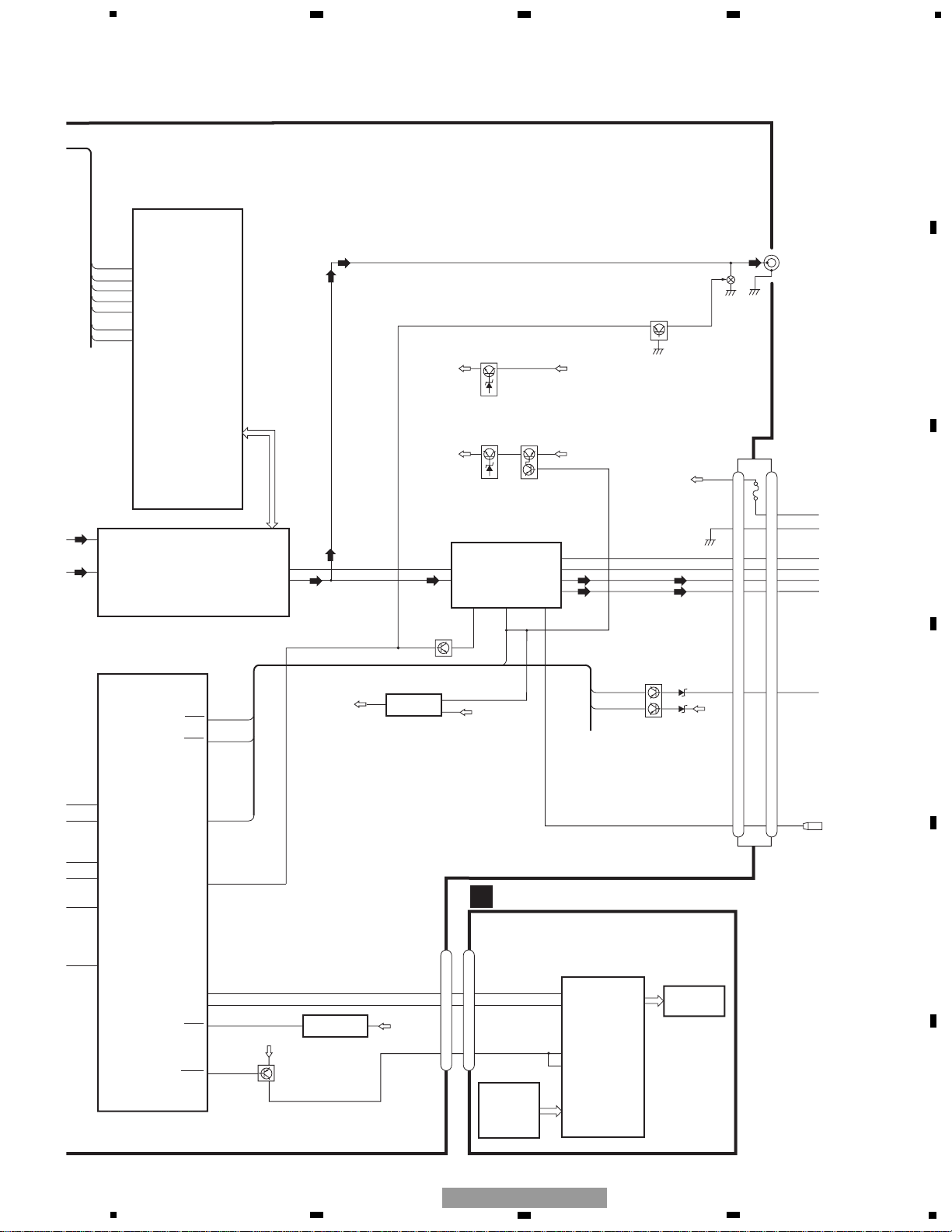
14
VDCONT
Q991
Q992
B.U
ANTENNA
CN402
IN2_
IN3_
2
3
CN651
CO
29
28
27
65
41
VDC
DSC
LOEJ
CONT
LOE
CON
TUNER AMP UNIT
VD
A
CN701
CN101
Q101
M
LASER
DIODE
MONITOR
DIODE
CLAMP
HOME
X201
12EJ 8EJ DSCSNS
FOCUS ACT.
SPINDLE
MOTOR
M
CARRIAGE
MOTOR
LOADING/
TRACKING ACT.
LD+
MD
FOP
TOP
14
5
4
1
PICKUP UNIT
(SERVICE)(P10)
HOLOGRAM
UNIT
IC 301
BA5996FP
IC 201
UPD63712GC
IC 701
NJM2391DL1-33
3.3V REGULATOR
SERVO
CONTROL,
DSP,
LPF, DAC
ACT,MOTOR
DRIVER
1
2
VD
VD
3R3V
7
CONT
11
CLMP CLAMSW
5
LOEJ
6
DSCSNS DSCSNS
8
21
20
15
11
17
16
14
LOUT
LOUT
TOP
FOP
16
SOP
15
SOM
17
LCOM
18
LCOP
22
1
LOEJ
23
20
LOUT
XTAL
xtal
24
9
CONT
12
FOP
FD, TD, SD, MD
AC, F, E, BD
1
LD
2
PD
42
LIMIT
3
13
TOP
D
CD CORE UNIT(S10)
C
CLA
VDD
CE2
CE1
VDD
IC652
TC7SET08FU
16
XSI
1
5
4
FMRF
ANT adj
RF adj
FM ANT
T51
CF52
CF51
VCC
VDD_3.3
VCC
TUN3V
3.3V
2.5V
IC 4
3.3V 2.5V
←
IC 2
2.5V
CE2
ROM_VDD
SL
DI
TUNPDI
CK TUNPCK
CE1
LDET
DO TUNPDO
6 13 5 10 9 8 11 14
1
3
4
17
IC 1
3.3V
AM ANT
FMRF
ATT
LPF
OSC
IC 3 EEPROM
5.0V
IC 5
5V 3.3V
←
ATT
MIXER, IF AMP
DET, FM MPX
23
Lch
- DEH-5/XU/UC
1
234
12
34
F
E
D
C
B
A
DEH-5/XU/UC
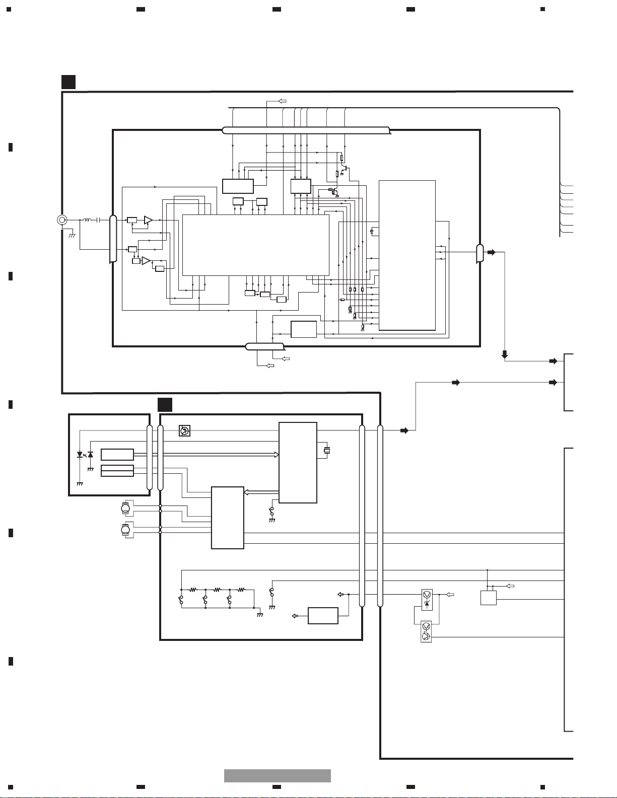
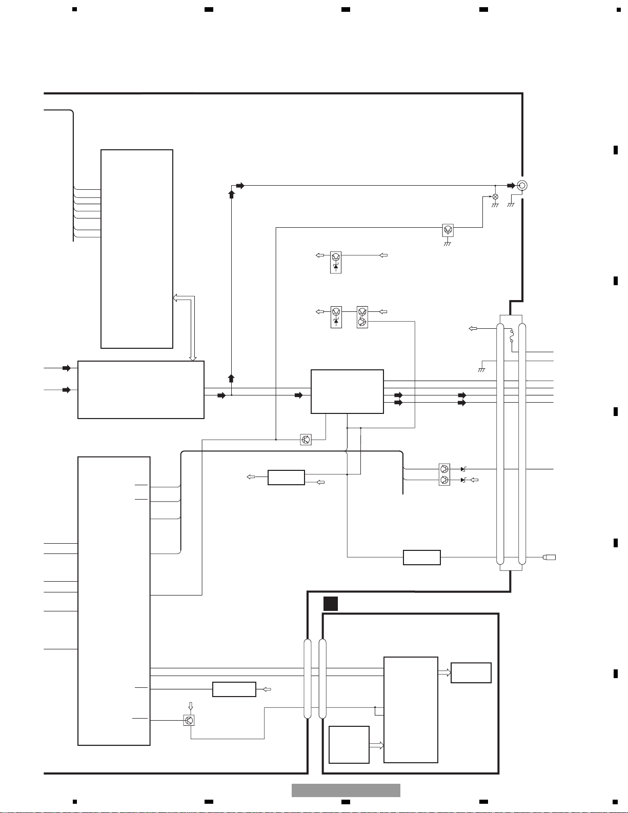
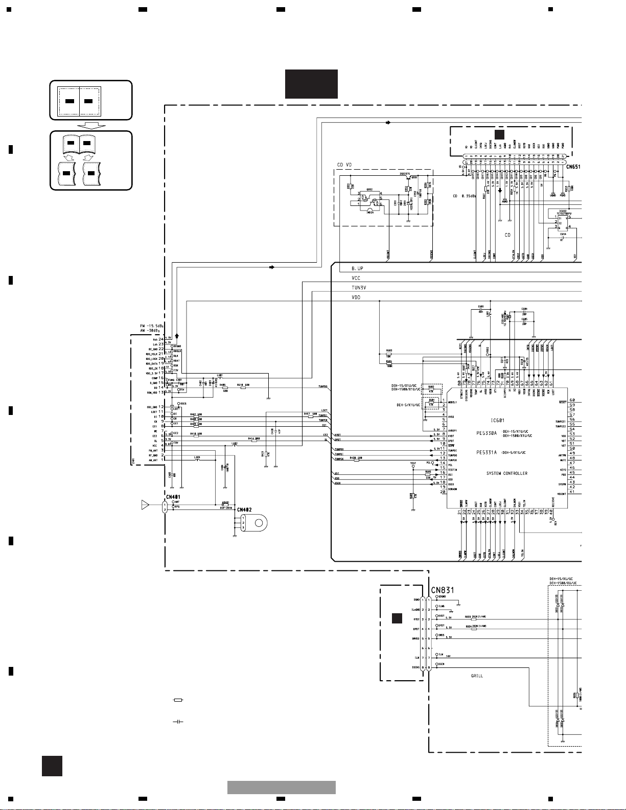
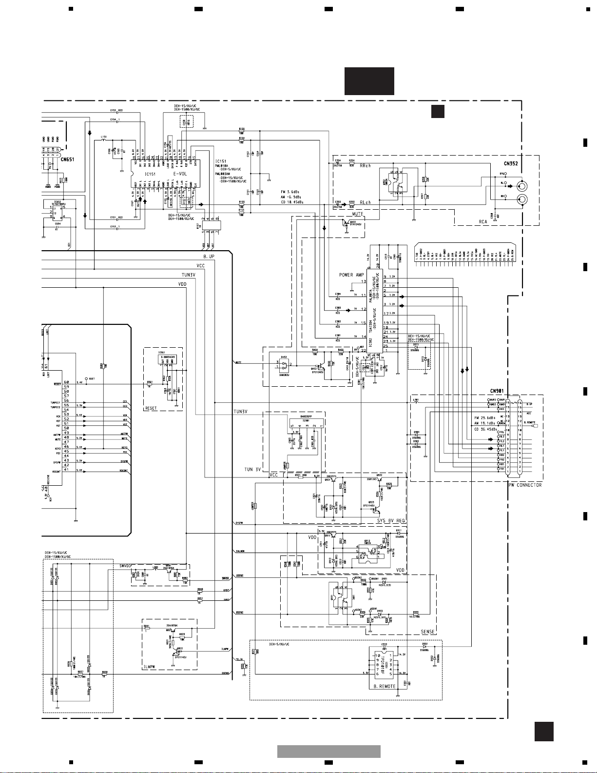
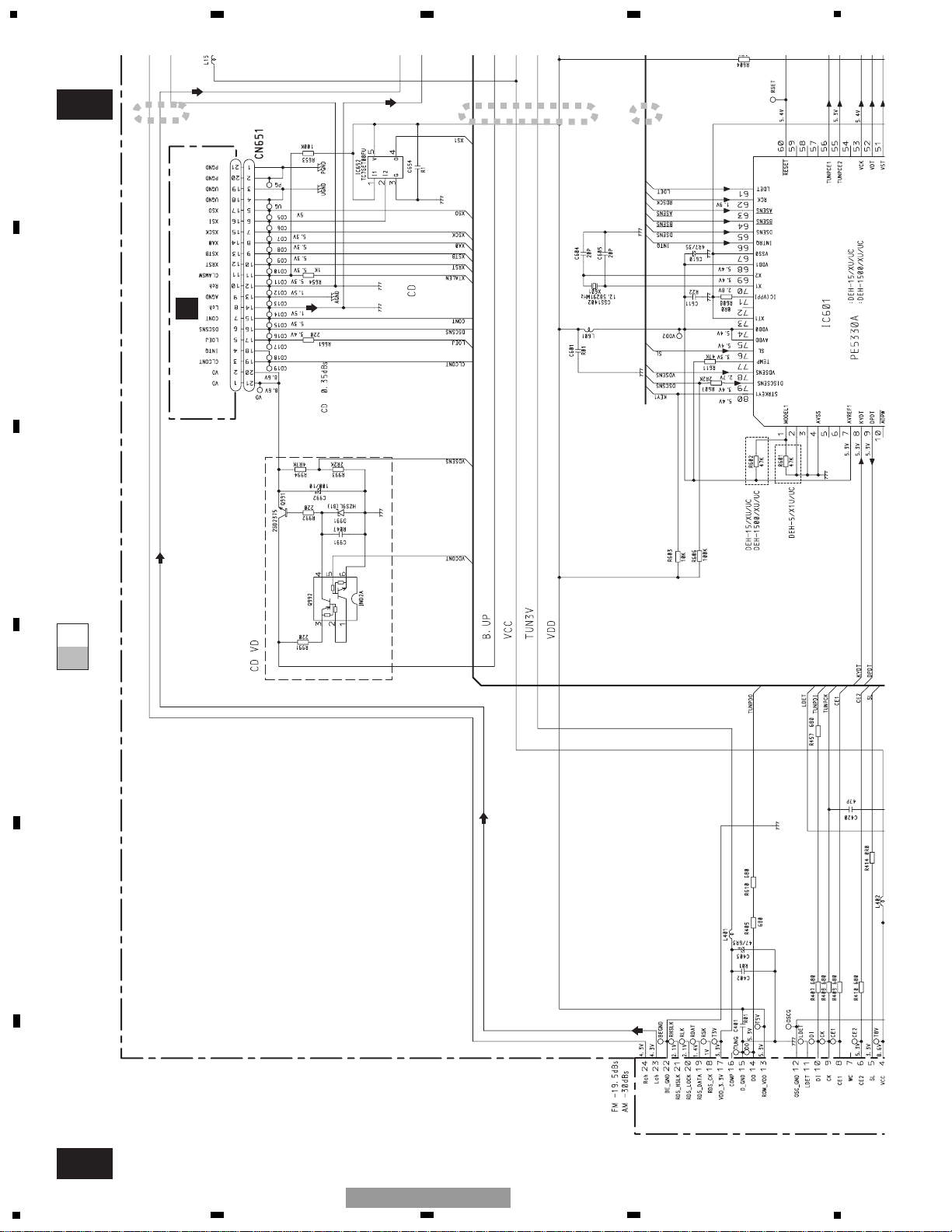
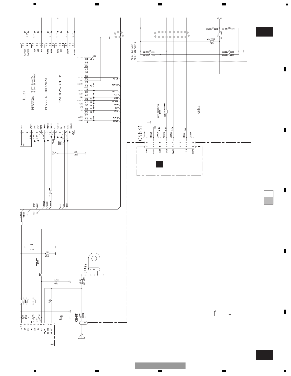
3. BLOCK DIAGRAM AND SCHEMATIC DIAGRAM
3.1 BLOCK DIAGRAM
KYDT
DPDT
IC 1801
PD6340A
3
4
5
3
4
5
KEY MATRIX
LDET
SL
TUNPCE2
TUNPCE1
TUNPDI
TUNPDO
IN2_L
IN3_L
61
76
55
56
11
12
TUNPCK
13
2
3
SYSTEM
CONTROLLER
IC 601 (1/2)
PE5331A
VCK
VDT
VST
B.U
VDD
Q911
B.U
BACKUP
FLFL+
RLRL+
ACC
16
15
7
5
8
6
14
ELECTRONIC VOLUME
IC 151
PML010A
SYSTEM
CONTROLLER
IC 601(2/2)
PE5331A
ASENS
64
BSENS
63
SYSPW
43
MUTE
48
KYDT
8
DPDT
9
RESET
60
SWVDD
21
Frontout_L
10
Rearout_L
11
POWER AMP
IC 302
TDA7384
14
12
22 4
5
3
21
23
FL
MUTE STBY
RL
B.U
bsens
asens
Q931
Q452 MUTE
KEYBOARD UNIT
CN1801CN831
LCD
20
18
Q801
RESET
IC 603
S-80834ANY
VDD
12
SYSPW
11
B.REM
FUSE
10A
29
28
27
65
41
VDCONT
DSCSNS
LOEJ
CONT
VST/ VCK/ VDT
VDD
VDD
VLCD
56
10
CN901
Q 352
CN352
REAR L CH
Q453
BACK UP
FLFL+
RLRL+
B.REM
ACC
GND
B
ANTPW
49
KYDT
DPDT
SW5V
KEY CONTROLLER
LCD DRIVER
16
15
7
5
8
6
14
11
SYSPW
Q921
Q922
B.U
VCC
Q923
ANTPW
B.REMOTE
IC 551
TPD1018F
6
1
4
1
RESET
IC 961
S-80834CNY
12
SYS 8V REGULATOR
VDD REGULATOR
CLAMSW
CE2
CE1
TUN3V
TUN 3V
IC 901
BA033SFP
4
VCC
16
XSI
5
6
7
8
F
E
D
C
B
A
5
6
7
8
DEH-5/XU/UC
15
16
VDCONT
Q991
Q992
B.U
ANTENNA
CN402
IN2_
IN3_
2
3
CN651
C
29
28
27
65
41
VDC
DSC
LOEJ
CONT
LOE
CON
TUNER AMP UNIT
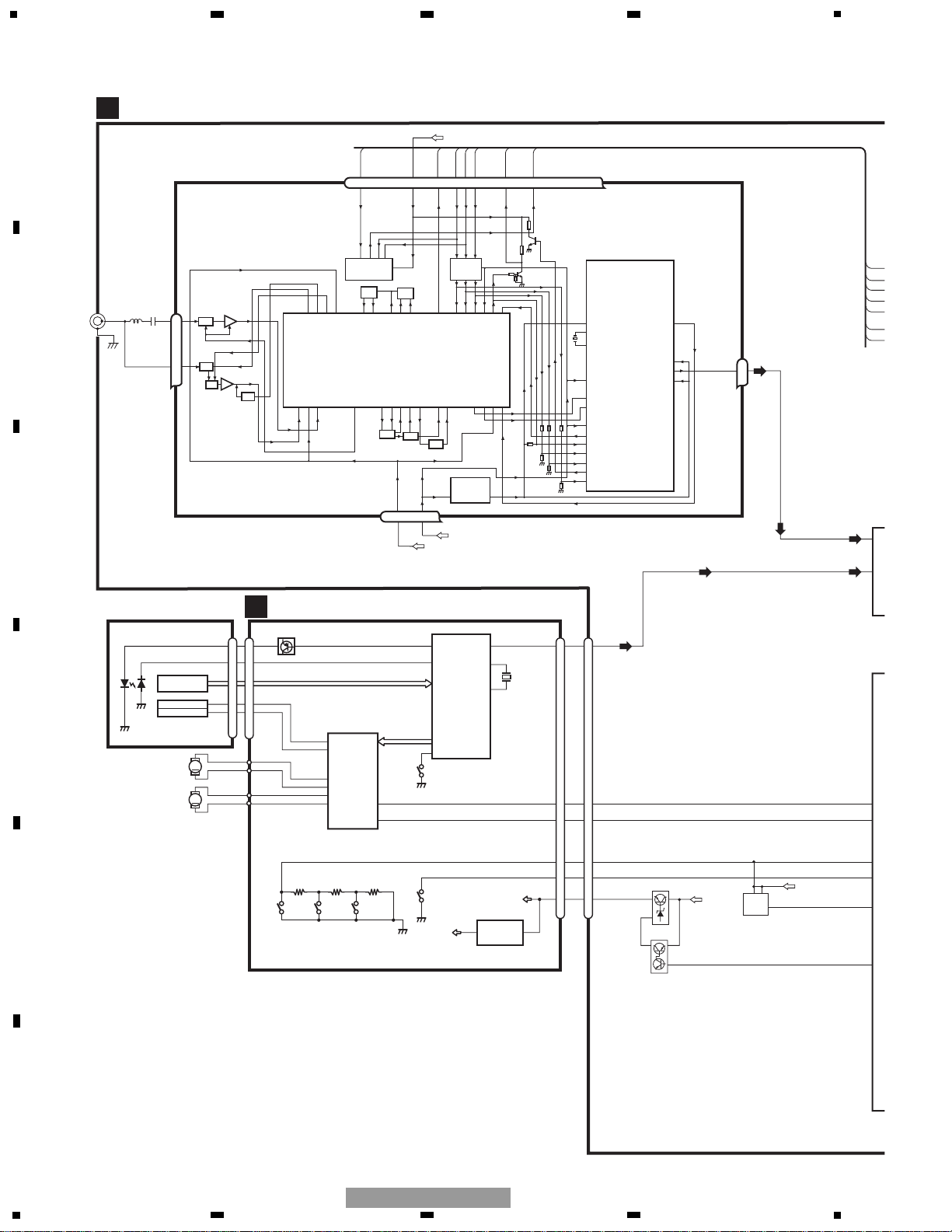
- DEH-15/XU/UC,1500/XU/UC
VD
A
CN701
CN101
Q101
M
LASER
DIODE
MONITOR
DIODE
CLAMP
HOME
X201
12EJ 8EJ DSCSNS
FOCUS ACT.
SPINDLE
MOTOR
M
CARRIAGE
MOTOR
LOADING/
TRACKING ACT.
LD+
MD
FOP
TOP
14
5
4
1
PICKUP UNIT
(SERVICE)(P10)
HOLOGRAM
UNIT
IC 301
BA5996FP
IC 201
UPD63712GC
IC 701
NJM2391DL1-33
3.3V REGULATOR
SERVO
CONTROL,
DSP,
LPF, DAC
ACT,MOTOR
DRIVER
1
2
VD
VD
3R3V
7
CONT
11
CLMP CLAMSW
5
LOEJ
6
DSCSNS DSCSNS
8
21
20
15
11
17
16
14
LOUT
LOUT
TOP
FOP
16
SOP
15
SOM
17
LCOM
18
LCOP
22
1
LOEJ
23
20
LOUT
XTAL
xtal
24
9
CONT
12
FOP
FD, TD, SD, MD
AC, F, E, BD
1
LD
2
PD
42
LIMIT
3
13
TOP
D
CD CORE UNIT(S10)
C
CLA
VDD
CE2
CE1
VDD
IC652
TC7SET08FU
16
XSI
1
5
4
FMRF
ANT adj
RF adj
FM ANT
T51
CF52
CF51
VCC
VDD_3.3
VCC
TUN3V
3.3V
2.5V
IC 4
3.3V 2.5V
←
IC 2
2.5V
CE2
ROM_VDD
SL
DI
TUNPDI
CK TUNPCK
CE1
LDET
DO TUNPDO
6 13 5 10 9 8 11 14
1
3
4
17
IC 1
3.3V
AM ANT
FMRF
ATT
LPF
OSC
IC 3 EEPROM
5.0V
IC 5
5V 3.3V
←
ATT
MIXER, IF AMP
DET, FM MPX
23
Lch
1
234
12
34
F
E
D
C
B
A
DEH-5/XU/UC
17
KYDT
DPDT
IC 1801
PD6340A
3
4
5
3
4
5
KEY MATRIX
LDET
SL
TUNPCE2
TUNPCE1
TUNPDI
TUNPDO
IN2_L
IN3_L
61
76
55
56
11
12
TUNPCK
13
2
3
SYSTEM
CONTROLLER
IC 601 (1/2)
PE5330A
VCK
VDT
VST
B.U
VDD
Q911
B.U
BACKUP
FL-
FL+
RL-
RL+
ACC
16
15
7
5
8
6
14
ELECTRONIC VOLUME
IC 151
PML003AM
SYSTEM
CONTROLLER
IC 601(2/2)
PE5330A
ASENS
64
BSENS
63
SYSPW
43
MUTE
48
KYDT
8
DPDT
9
RESET
60
SWVDD
21
Frontout_L
10
Rearout_L
11
POWER AMP
IC 302
PAL007A
14
12
22 4
5
3
21
23
FL
MUTE STBY
25
RL
B.U
bsens
asens
Q931
Q452 MUTE
KEYBOARD UNIT
CN1801CN831
LCD
20
18
Q801
RESET
IC 603
S-80834ANY
VDD
12
SYSPW
11
B.REM
FUSE
10A
29
28
27
65
41
VDCONT
DSCSNS
LOEJ
CONT
VST/ VCK/ VDT
VDD
VDD
VLCD
56
10
CN901
Q 352
CN352
REAR L CH
Q453
BACK UP
FLFL+
RLRL+
B.REM
ACC
GND
B
KYDT
DPDT
SW5V
KEY CONTROLLER
LCD DRIVER
16
15
7
5
8
6
14
11
SYSPW
Q921
Q922
B.U
VCC
Q923
1
4
RESET
IC 961
S-80834CNY
12
SYS 8V REGULATOR
VDD REGULATOR
CLAMSW
CE2
CE1
TUN3V
TUN 3V
IC 901
BA033SFP
4
VCC
16
XSI
5
6
7
8
F
E
D
C
B
A
5
6
7
8
DEH-5/XU/UC
18
A-a A-b
A-a
A-b
A-b
A-a
Large size
SCH diagram
Guide page
Detailed page
Note: When ordering service parts, be sure to refer to " EXPLODED VIEWS AND PARTS LIST" or
"ELECTRICAL PARTS LIST".
A-a
A
The > mark found on some component parts indicates
the importance of the safety factor of the part.
Therefore, when replacing, be sure to use parts of
identical designation.
Decimal points for resistor
and capacitor fixed values
are expressed as :
2.2 2R2
0.022 R022
←
←
Symbol indicates a resistor.
No differentiation is made between chip resistors and
discrete resistors.
NOTE :
Symbol indicates a capacitor.
No differentiation is made between chip capacitors and
discrete capacitors.
B
CN1801
C
CN701
FM/AM TUNER UNIT
1
234
12
34
F
E
D
C
B
A
DEH-5/XU/UC
3.2 OVERALL CONNECTION DIAGRAM(GUIDE PAGE)
19
A-b
A
CEK1136
>
10A
RR+
RR-
FR+
FR-
FL-
RL+
FL+
RL-
GND
REAR
L CH
REAR
R CH
A
TUNER AMP UNIT
600
µH
5
6
7
8
F
E
D
C
B
A
5
6
7
8
DEH-5/XU/UC
20
1
234
12
34
F
E
D
C
B
A
DEH-5/XU/UC
A-a
A-b
A-a
A-a
A-b
C
CN701
FM/AM TUNER UNIT
1
2 3
21
5
6
7
8
F
E
D
C
B
A
5
6
7
8
DEH-5/XU/UC
A-a
A-b
A-a
A-a
A-b
The > mark found on some component parts indicates
the importance of the safety factor of the part.
Therefore, when replacing, be sure to use parts of
identical designation.
Decimal points for resistor
and capacitor fixed values
are expressed as :
2.2 2R2
0.022 R022
←
←
Symbol indicates a resistor.
No differentiation is made between chip resistors and
discrete resistors.
NOTE :
Symbol indicates a capacitor.
No differentiation is made between chip capacitors and
discrete capacitors.
B
CN1801
4 5
 Loading...