


CT-W504R
STEREO DOUBLE CASSE'n'E DECK
CT- /504R
CT-W404R
CT-W204
)_ _==m=_==== CT-WSO4_II
U _i ._..=,---._. i_ll l======_==J
I. I°l. Ii. Ioi. II ...........
.., o c3 zD_®.:o ... -=.
• The above illustration shows CT-W504R.
• For the demo function, refer to back cover of these operating
instructions.
Thank you forbwing this Pioneer product.
Please read through these operating instructions so you will
know how to operate your unit properly. After you have fin-
ished reading the instructions, keep the manual in a safe
place for future reference.
In some countries or regions, the shape of the power plug
and power outlet may sometimes differ from that shown in
the explanatory drawings. However, the method of connect-
ing and operating the unit is the same.
WARNING:To PREVENT FIRE OR SHOCK HAZARD,
DO NOT EXPOSE THIS APPLIANCE TO RAIN OR MOIS-
TURE.
IMPORTANT NOTICE
The serial number for this equipment is located on the rear
panel. Please write this serial number on your enclosed war-
ranty card and keep it in a secure area. This is for your secu-
rity.
THE POWER SWITCH IS SECONDARY CONNECTED I
AND THEREFORE DOES NOT SEPARATE THE UNIT
....... AUTON_ _tS_ld_4
[For Canadian model]
CAUTION: TO PREVENT ELECTRIC SHOCK DO NOT
USE THIS (POLARIZED) PLUG WITH AN EXTENSION
CORD, RECEPTACLE OR OTHER OUTLET UNLESS THE
BLADES CAN BE FUM.Y INSERTED TO PREVENT BLADE
EXPOSURE.
ATTENTION: POUR PREVENIR LES CHOCS
ELECTRIQUES NE PAS UTILISER CETTE FICHE
POLARISEE AVEC UN PROLONGATEUR UNE PRISE DE
COURANT OU UNE AUTRE SORTIE DE COUP,ANT, SAUF
Sl LES LAMES PEUVENT ETRE INSEREES A FOND SANS
EN LAISSER AUCUNE PARTIE A DECOUVERT.
J "Thisproduct complies with the Radiointerference requirementsI
of the EC(European Community) Directive 87/308/EEC."
CAUTION
I
IFROM MAINS POWER IN STANDBY POSITION.
This product satisfies FCC regulations when shielded
cables and connectors are used to connect the unit to
other equipment. To prevent electromagnetic interference
with electric appliances such as radios and televisions,
use shielded cables and connectors for connections.
! !
I
IMPORTANT 1
The lightning flash with arrowhead, within an
equilateral triangle, is intended to alert the user to the
presence of uninsulated "dangerous voltage" within the
product's enclosure that may be of sufficient
magnitude to constitute a risk of electric shock to
persons.
CAUTION
CAUTION:
TO PREVENT THE RISK OF ELECTRIC SHOCK, DO
NOT REMOVE COVER (OR BACK). NO USER-SER-
VICEABLE PARTS INSIDE. REFER SERVICING TO
QUALIFIED SERVICE PERSONNEL.
PlOI IlEEIR °
The Art of _nmem
The exclamation point within an equilateral triangle is
intended to alert the user to the presence of important
operating and maintenance (servicing) instructions in
the literature accompanying the applia nce.
IMPORTANT 2
FOR USE IN THE UNITED
KINGDOM
1he wires in this mains lead are €oloured in
accordance with the following code :
If the plug provided is unsuitable for your socket out-
lets, the plug must be cut off and a suitable plug fit-
ted.
Blue Neutral
Brown Live
SAFETY INSTRUCTIONS
The cut-off plug should be disposed of and must not be in-
serted into any 13 amp socket as this can result in electric
shock. The plug or adaptor or the distribution panel should
be provided with 5 amp fuse. As the colours of the wires in
the mains lead of this appliance may not correspond with
coloured markings identifying the terminals in your plug,
proceed as follows :
The wire which is coloured blue must be connected to the
terminal which is marked with the letter N or coloured black.
The wire which is coloured brown must be connected
to the terminal which is marked with the letter L or coloured
red.
Do not connect either wire to the earth terminal of a
three pin plug.
NOTE
After replacing or changing a fuse, the fuse cover in the
plug must be replaced with a fuse cover which corre-
sponds to the colour of the insert in the base of the plug
or the word that is embossed on the base of the plug,
and the appliance must not be used without a fuse
cover. If lost replacement fuse covers can be obtained
from: your dealer.
Only 5 A fuses approved by B.S.I. or A.S.T.A to B.$.
1362 should be used.
READ INSTRUC'NOI_ - All the safety and operating
instructions should be read before the appliance is
operated.
RETAIN INSTRUCTIONS -The safety and operating
instructions should be retained for future refer-
ence.
HEED WARNING - All warnings on the appliance and
in the operating instructions should be adhered to.
FOLLOW INSTRUCTIONS - All operating and use in-
structions should be followed.
WATER AND MOISTURE - The applianCe should not
be used near water - for example, near a bathtub,
washbowl, kitchen sink, laundry tub, in a wet base-
ment, or near a swimming pool. etc.
LOCATION - The appliance should be installed in a
stable location.
WALL OR CEILING MOUNTING - The appliance
should not be mounted to awall or ceiling.
VENTILATION - The appliance should be situated so
that its location or position does not interfere with
its proper ventilation. For example, the appliance
should not be situated on a bed. sofa, rug, or simi-
isr surface that may block the ventilation openings;
or, placed in a built4n installation, such as a book-
case or cabinet that may impede the flow of air
through the ventilation openings.
HEAT- The appliance should be situated away from
heat sources such as radiators, heat registers,
stoves, or other appliances (including amplifiers)
that produce heat.
POWER SOURCES- The appliance should be con-
nected to a power supply only of the type de-
scribed in the operating instructions or as marked
on the appliance.
PO_R-CORD PROTECTION - Power-supply cords
should be routed so that they are not likely to be
walked on or pinched by items placed upon or
against them. Pay particular attention to cords st
plugs, convenience receptacles, and the point
where they exit from the appliance.
POLARIZATION - If your purchased product is pro-
vided with a polarized power plug, please read the
following instructions. This product is equipped
with a poisdzed alternating current line plug {a plug
having one blade wider than the other). This plug
will fit into the power outlet only one way. This is a
safety feature. If you are unable to insert the plug
fully into the outlet, try reversing the plug. If the
plug should still fail to fit, contact your electrician to
replace your obsolete outlet. Do not defeat the
safety purpose of the polarized plug.
CLEANING - The appliance should be cleaned only
with a polishing cloth or a soft dry cloth. Never
clean with furniture wax, benzine, insecticides or
other volatile liquids since they may corrode the
cabinet.
POWER LINES - An outdoor antenna should be lo-
cated away from power lines.
NONUSE PERIODS - The power cord of the appliance
should be unplugged from the outlet when left un-
used for a long period of time,
OBJECT AND LIQUID ENTRY - Care should be taken
so that objects do not fall and liquids are not spilled
into the enclosure through openings.
DAMAGE REQUIRING SERVICE - The appliance
should be serviced by a Pioneer authorized service
center or qualified service personnel when:
• The power-supply cord or the plug has been dam-
aged.
• Objects have fallen, or liquid has been spilled into
the appliance.
• The appliance has been exposed to rain.
• The appliance does not appear to operate normally
or e0<hibitsa marked change in performance.
• The appliance has been dropped or the enclosure
damaged.
SERVICING -The user should not attempt to service
the appliance beyond that described in the oper-
ating instructions. All other servicing shoutd be
referred to qualified service personnel.
ANTENNA
LEAD IN
J WIRE
FIG. A (NEC ART 250. PART H)
GROUND.
DISCHARGE UNIT
(NEC SECTION 810 - 20)
GROUNDING CONDUCTORS
(NEC SECTION 810-21)
ANTENNA
GROUND CLAMPS
POWER SERVICE GROUNDING
ELECTRODE SYSTEM
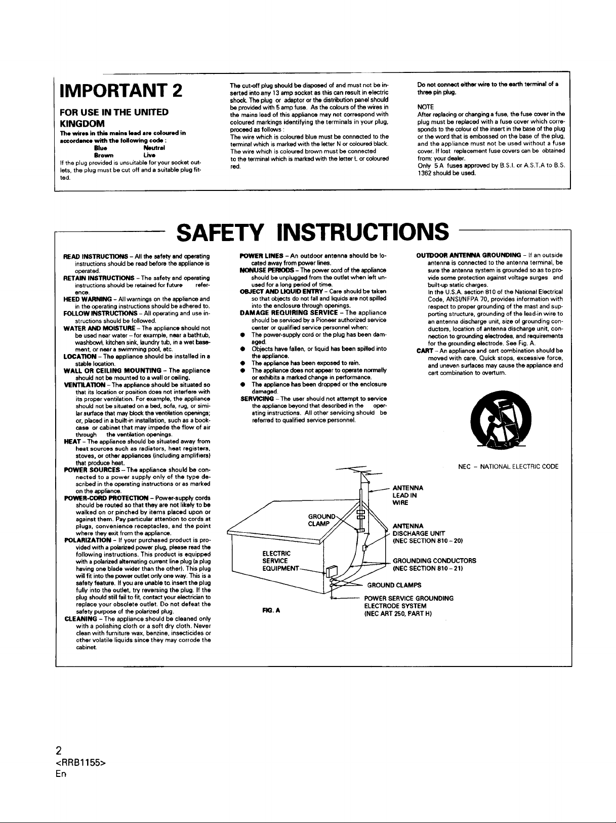
OUIDOOR ANTENNA GROUNDING - If an outside
antenna is connected to the antenna terminal, be
sure the antenna system is grounded so as to pro-
vide some protection against voltage surges and
built-up static charges.
In the U.S.A. section 810 of the National Electrical
Code, ANSI/NFPA 70, provides information with
respect to proper grounding of the mast and sup-
porting structure, grounding of the lead-in wire to
an antenna discharge unit, size of grounding con-
ductors, location of antenna discharge unit, con-
nection to grounding electrodes, and requirements
for the grounding electrode. See Fig. A.
CART - An appliance and cart combination should be
moved with care. Quick stops, excessive force,
and uneven surfaces may cause the appliance and
cart combination to overturn.
NEC - NATIONAL ELECTRIC CODE
2
<RRB1155>
En

This equipment has been tested and found to comply with the limits for a Class B digital device, pursuant to Part 15 of the FCC Rules.
These limits are designed to provide reasonable protection against harmful interference in a residentialinstallation. This equipment gen-
erates, uses, and can radiate radio frequency energy and, if not installed and used in accordance with the instructions, may cause harmful
interference to radio communications. However, there is no guarantee that interference will not occur in aparticular installation. If this
equipment does cause harmful interference to radio or television reception, which can be determined by turning the equipment off and on,
the user is encouraged to try to correct the interference by one or more of the following measures:
- Reorient or relocate the receiving antenna.
- Increase the separation between the equipment andreceiver.
-Connect the equipment into an outlet on a circuit different from that to which the receiver is connected.
-Consult the dealer or an experienced radiofrV technician for help.
Information to User I
Alteration ormodifications carried out withoutappropriateauthorizationmay invalidatethe user'sright to operatethe equipment.
[For Canadian model]
This digital apparatus does not exceed the Class B limits for radio noise emissions from digital apparatus set out in the Radio
Interference Regulations of the Canadian Department of Communications.
CONDENSATION
When the unit is brought into a warm room from previouslycold conditionsor when the room temperature is suddenlyincreased,condensa-
tion may from inside and the unit may not beable to attain its full performance. Ifthis occurs, allow the unit to standfor about an hour or raise
the room temperature gradually.
I
I
We Want You Listening For A Lifetime
@
Selecting fine audio equipment such as the unit you've just pur- Decibel
chased is only the startof your musical enjoyment. Now it's time to Level
consider how you can maximize the fun and excitement your equip-
ment offers. This manufacturer and the Electronic Industries 30
Association's Consumer Electronics Group want you to get the 40
most out of your equipment by playing it at a safe level. One that 50
lets the sound come through loud and clear without annoying blar- 60
ing or distortion-and, most importantly, without affecting your sen- 70
sitive hearing. 80
Sound can be deceiving. Over time your hearing "comfort level"
adapts to higher volumes of sound. So what sounds "normal" can
actually be loud and harmful to your hearing. Guard against this by
setting your equipment at a safe level BEFORE your hearing
adapts.
To establish a safe level:
• Start your volume control at a low setting.
• Slowly increase the sound until you can hear it comfortably and
clearly, and without distortion.
Once you have established a comfortable sound level:
• Set the dial and leave it there.
Taking a minute to do this now will help to prevent hearing dam-
age or loss in the future. After all, we want you listening for a life-
time.
Used wisely, your new sound equipment will provide a lifetime
of fun and enjoyment. Since hearing damage from loud noise is
often undetectable until it is too late, this manufacturer and the
Electronic Industries Association's Consumer Electronics Group
recommend you avoid prolonged exposure to excessive noise. This
list of sound levels is included for your protection.
THE FOLLOWING NOISES CAN BE DANGEROUS
UNDER CONSTANT EXPOSURE
90
100
120
140
180
Information courtesy of the Deafness Research Foundation.
@
Example_
Quiet library, soft whispers
Living room, refrigerator, bedroom away from traffic
Light traffic, normal conversation, quiet office
Air conditioner at 20 feet, sewing machine
Vacuum cleaner, hair dryer, noisy restaurant
Average city traffic, garbage disposals, alarm clock
at two feet.
Subway, motorcycle, truck traffic, lawn mower
Garbage truck, chain saw, pneumatic drill
Rock band concert in front of speakers, thunderclap
Gunshot blast, jet plane
Rocket launching pad
I,_T_]NING
F._ bk_z=
<RRB1155>
3
En
Ico.T .Ts h I
INSTALLATION ............................................................................. 4
MAINTENANCE ............................................................................. 4
HANDLING CASSETTE TAPES ....................................................... 5
CONNECTIONS ............................................................................. 6
FRONT PANEL FACILITIES ............................................................ 7
PLAYBACK ................................................................................... 11
SINGLE PLAYBACK ................................................................ 11
BLANK SKIP .......................................................................... 11
RELAY PLAYBACK ................................................................. 11
MUSIC SEARCH ..................................................................... 12
RECORDING ................................................................................. 13
RECORDING ........................................................................... 13
RECORDING MUTE ............................................................... 13
ERASING A TAPE ................................................................... 13
CD • DECK SYNCHRO RECORDING (CT-W504R only) .......... 14
TAPE COPYING ............................................................................ 15
TROUBLESHOOTING ................................................................... 16
SPECIFICATIONS ......................................................................... 18
I
When installing the deck, avoid locations with high
temperatures or humidity, and make sure that the
deck receives adequate ventilation.
• Do not install the deck in locations subject to direct sunlight, or
near a space heater or other heating device, as this may cause
damage to the finish or internal parts.
• Malfunctions may also result if the deck is installed in an exces-
sively humid or dusty location. Avoid installing the deck next to
kitchen counters or other locations subject to oily smoke or hu-
midity.
• If the deck is placed directly on top of an amplifier, it may pick up
humming or other noise. Also, if the amplifier generates a large
amount of heat, the deck may malfunction.
• If the deck is located near a television set, it may pick up inter
ference noise, which will be recorded as a whistling sound on the
tape. If this happens, move the deck further away from the tele-
vision set or turn the television set off when operating the deck.
• Do not place a cloth over the deck, or block the ventilation slots in
any way. The ventilation slots on this deck are necessary to keep
internal parts cool. If they are blocked, the deck may malfunction.
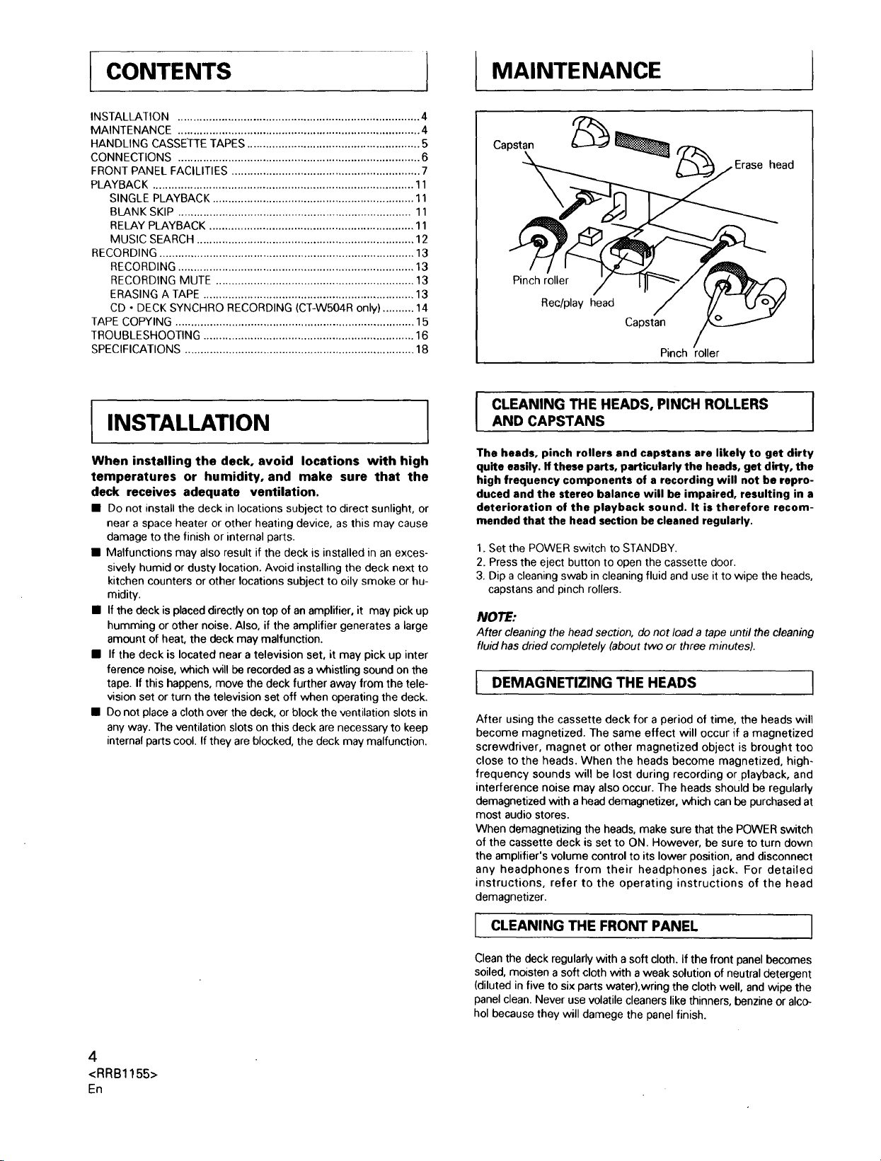
The heads, pinch rollers and capstans are likely to get dirty
quite easily. If these parts, particularly the heads, get dirty, the
high frequency components of a recording will not be repro-
duced and the stereo balance will be impaired, resulting in a
deterioration of the playback sound. It is therefore recom-
mended that the head section be cleaned regularly.
1. Set the POWER switch to STANDBY.
2. Press the eject button to open the cassette door.
3. Dip a cleaning swab in cleaning fluid and use it to wipe the heads,
NOTE:
After cleaning the head section, do not load a tape until the cleaning
fluid has dried completely (about two or three minutes).
I
After using the cassette deck for a period of time, the heads will
become magnetized. The same effect will occur if a magnetized
screwdriver, magnet or other magnetized object is brought too
close to the heads. When the heads become magnetized, high-
frequency sounds will be lost during recording or playback, and
interference noise may also occur. The heads should be regularly
demagnetized with a head demagnetizer, which can be purchased at
most audio stores.
When demagnetizing the heads, make sure that the POWER switch
of the cassette deck is set to ON. However, be sure to turn down
the amplifier's volume control to its lower position, and disconnect
any headphones from their headphones jack. For detailed
instructions, refer to the operating instructions of the head
demagnetizer.
MAINTENANCE
Capstan
Erase head
Pinch roller
Rec/play head
Capstan
Pinch roller
CLEANING THE HEADS, PINCH ROLLERS I
AND CAPSTANS
capstans and pinch rollers.
DEMAGNETIZING THE HEADS
I
IINSTALLATION
I
4
<RRB1155>
En
CLEANING THE FRONT PANEL ]
J
Clean the deck regularly with a soft cloth. If the front panel becomes
soiled, moisten a soft cloth with a weak solution of neutral detergent
(diluted in five to six parts water),wring the cloth well, and wipe the
panel clean. Never use volatile cleaners like thinners, benzine or alco-
hol because they will damege the panel finish.
HANDLING CASSETTE TAPES
,1
Turn pencil to remove
tape slack
For erasure prevention
remove
Cover prevention
adhesive tape
Tab for
Tab for
Side B
I CHECK CASSE'R'E BEFORE USE
Check the fotlowing items before loading a cassette tape:
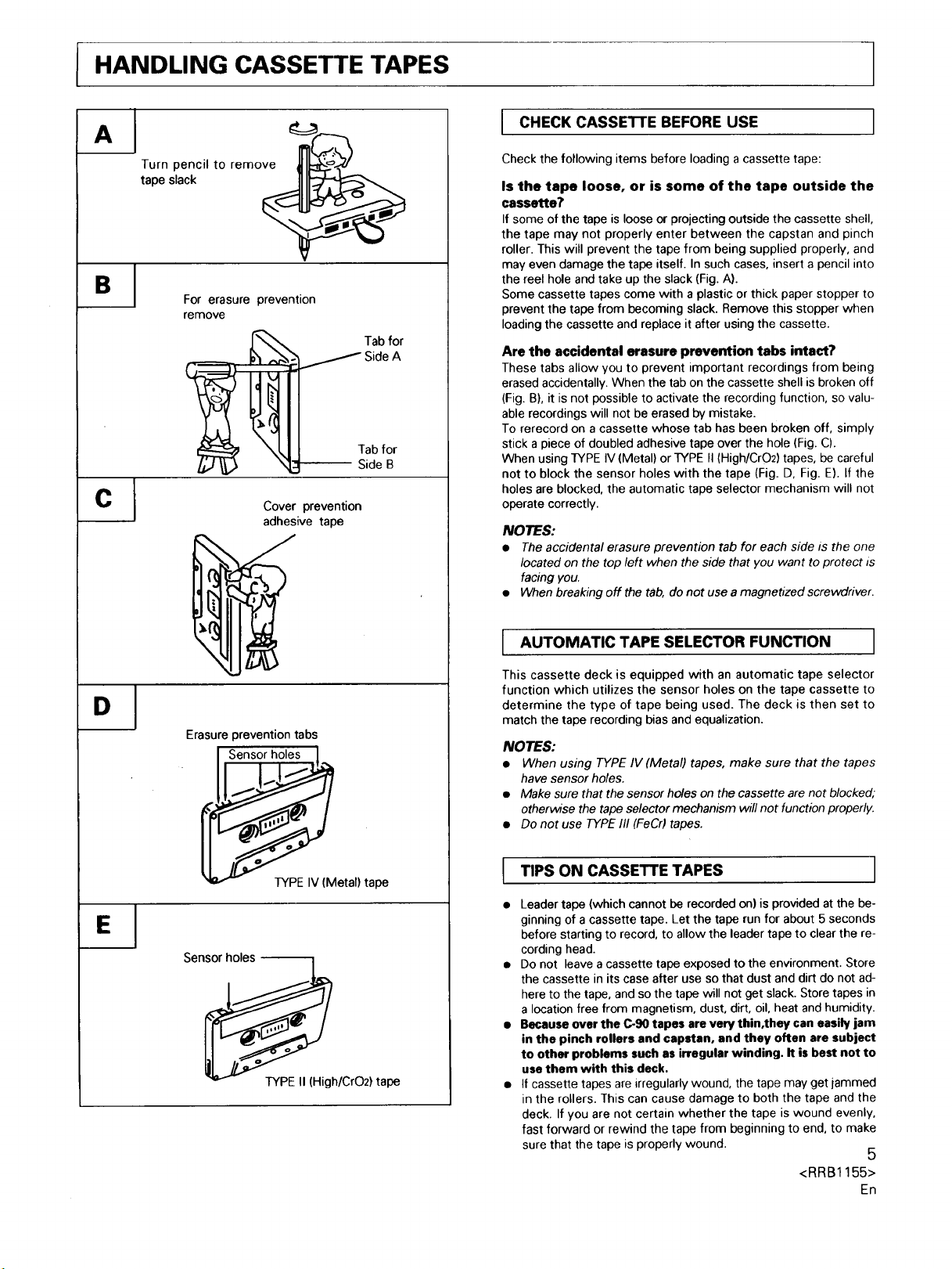
Is the tape loose, or is some of the tape outside the
cassette?
If some of the tape is loose or projecting outside the cassette shell,
the tape may not properly enter between the capstan and pinch
roller. This will prevent the tape from being supplied properly, and
may even damage the tape itself. In such cases, insert a pencil into
the reel hole and take up the slack (Fig. A).
Some cassette tapes come with a plastic or thick paper stopper to
prevent the tape from becoming slack. Remove this stopper when
loading the cassette and replace it after using the cassette.
Are the accidental erasure prevention tabs intact?
These tabs allow you to prevent important recordings from being
erased accidentally. When the tab on the cassette shell is broken off
(Fig. B), it is not possible to activate the recording function, so valu-
able recordings will not be erased by mistake.
To rerecord on a cassette whose tab has been broken off, simply
stick a piece of doubled adhesive tape over the hole (Fig. C).
When using TYPE IV (Metal) or TYPE fl (High/CrO2) tapes, be careful
not to block the sensor holes with the tape (Fig. D, Fig. E). If the
holes are blocked, the automatic tape selector mechanism will not
operate correctly.
NOTES:
• The accidental erasure prevention tab for each side is the one
located on the top left when the side that you want to protect is
facing you.
• When breaking off the tab, do not use a magnetized screwdriver.
Erasure prevention tabs
TYPE IV (Metal) tape
Sensor holes
TYPE II (High/CrO2) tape
I AUTOMATIC TAPE SELECTOR FUNCTION
This cassette deck is equipped with an automatic tape selector
function which utilizes the sensor holes on the tape cassette to
determine the type of tape being used. The deck is then set to
match the tape recording bias and equalization.
NOTES:
• When using TYPE IV (Metal) tapes, make sure that the tapes
have sensor holes.
• Make sure that the sensor holes on the cassette are not blocked;
otherwise the tape selector mechanism will not function properly.
• Do not use TYPE 111(FeCr) tapes.
TIPS ON CASSETTE TAPES
I
Leader tape (which cannot be recorded on) is provided at the be-
ginning of a cassette tape. Let the tape run for about 5 seconds
before starting to record, to allow the leader tape to clear the re-
cording head.
Do not leave a cassette tape exposed to the environment. Store
the cassette in its case after use so that dust and dirt do not ad-
here to the tape, and so the tape will not get slack. Store tapes in
a location free from magnetism, dust, dirt, oil, heat and humidity.
Because over the C-90 tapes are very thin,they can easily jam
in the pinch rollers and capstan, and they often are subject
to other problems such as irregular winding. It is best not to
use them with this deck.
If cassette tapes are irregularly wound, the tape may get iammed
in the rollers. This can cause damage to both the tape and the
deck. If you are not certain whether the tape is wound evenly,
fast forward or rewind the tape from beginning to end, to make
sure that the tape is properly wound.
<RRB1155>
5
En

CONNECTIONS
• This illustration shows CT-W504R.
Recording
connection
cord _ _ _PloorandYbeact,kon
I .Ec _*llJ/,
I° ° ° O'1
v v
Stereo Amplifier
TAPE REC/PLAY
jacks
• Read through the operating instructions of the stereo compo-
nents which you intend to connect to this unit.
• Turn the power on only after making all of the connections.
• Make sure that all of the connection plugs are inserted securely,
as improper connections may generate noise.
I CONNECTING THE RECORDING ANDPLAYBACK CORDS
1
Compact Disc Player
Remotel::n_r_[ _i_
CD • DECK SYNCHRO
control cord
(CT-W504R only)
CONTROL OUT ack
NOTES:
• Keep the input and output jacks connected between the amplifier
and this unit, otherwise, the CD • DECK SYNCHRO recording
cannot be carried out.
• Even when the CD player is connected to the amplifier with an
optical fiber cable, connect the CD player to the ampfifier or this
unit with the input and output cords that have pin plugs.
PIONEER SYSTEM REMOTE CONTROL
I
CD • DECK SYNCHRO
jack
I
Left channel _..._e plug
Right channel_ "" c_2_
Red plug
Connect the TAPE jacks of your amplifier to the LINE jacks of the
cassette deck. Be sure to connect the REC (INPUT) jacks of the deck
to the recording (output) jacks of the amplifier, and the PLAY (OUT-
PUT) jacks of the deck to the play (input) jacks of the amplifier.
• Connect the plugs properly:
Left channel -- White plug
Right channel -- Red plug
I D • DECK SYNCHRO RECORDING
(CT-WSO4R only)
• CD • DECK SYNCHRO recording can be carried out when this
unit is connected to a Pioneer CD player equipped with a CD -
DECK SYNCHRO jack.
Connection
Connect the CD • DECK SYNCHRO jack of this unit to the CD •
DECK SYNCHRO jack of the CD player using the supplied CD •
DECK SYNCHRO control cord.
6
<RRB1155>
En
CONTROL IN jack (CT-WSO4R/CT-W404R/CT-W204:
Australian models only)
Use the enclosed Remote Control Cord to connect this jack to the
CONTROL OUT jack of another component which bears the [] mark
(indicating that it is equipped with PIONEER System Remote Con-
trol). You will then be able to operate this unit using the Pioneer sys-
tem remote control unit. If the remote control unit does not have
separate buttons for deck I and deck II, or a selection button to
choose deck I or deck II, the buttons will only operate deck II. To
operate deck I with a remote control unit which was not designed
for double deck cassette players, see page 8.
CONTROL OUT jack
Intermediary jack which outputs signals from the CONTROL IN jack
of this unit to the input jack of another unit. Connect this jack to the
CONTROL IN jack of another component compatible with Pioneer
System Remote Control.
NOTE:
Be sure to connect both of the control cord's plugs securely to the
CONTROL IN and CONTROL OUT jacks. Do not connect only one
end of the cable.
CONNECTING THE POWER CORD I
Insert the power cord of the cassette deck into the accessory AC
outlet of your amplifier, or into a normal household outlet.
 Loading...