

2014
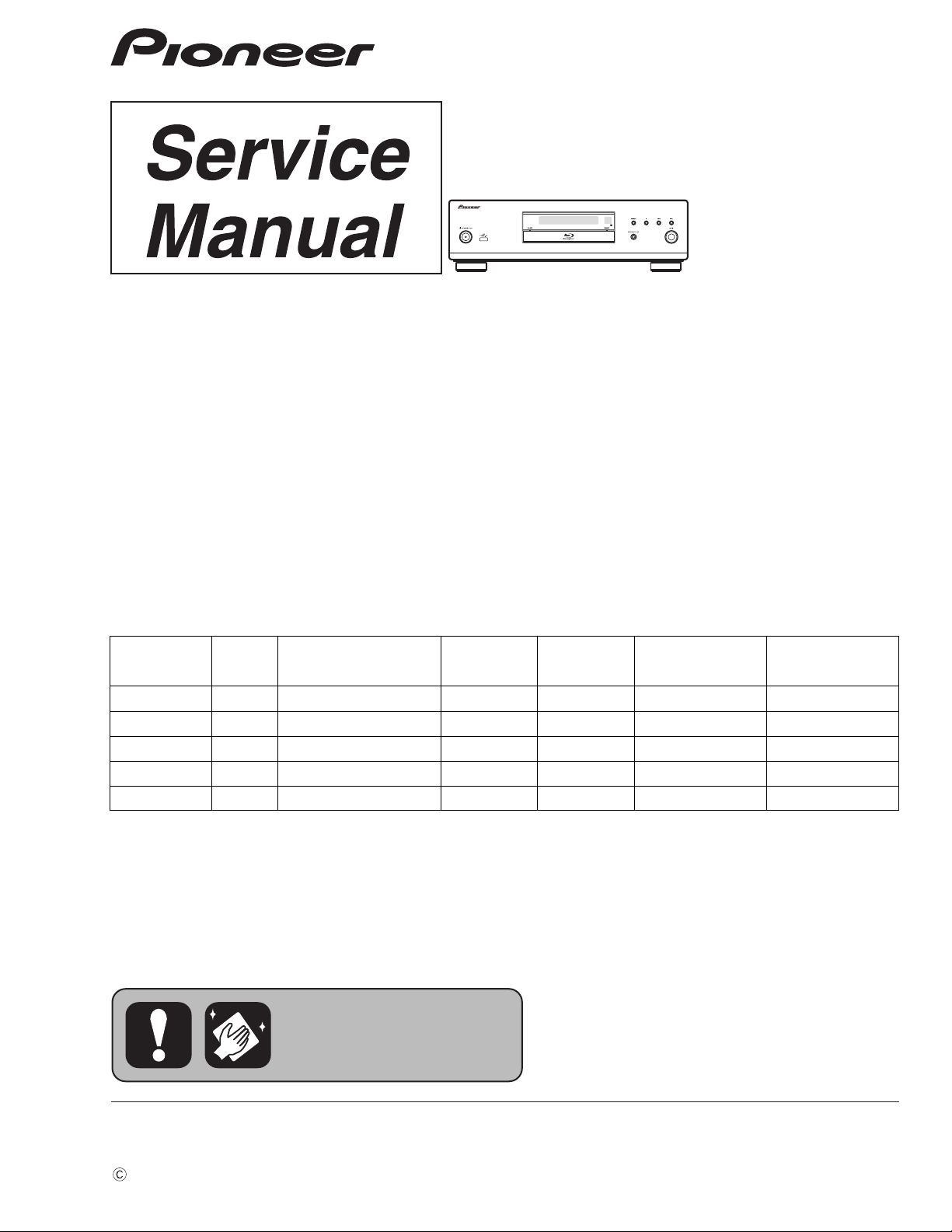
BDP-LX58-K
Blu-ray 3DTM PLAYER
BDP-LX58-K
BDP-LX58-S
BDP-LX58
THIS MANUAL IS APPLICABLE TO THE FOLLOWING MODEL(S) AND TYPE(S).
ORDER NO.
RRV4579
Model Type Power Requirement
BDP-LX58-K YXE8 AC 220 V to 240 V 2 B &&&&######YY YY: Europe
BDP-LX58-S YXE8 AC 220 V to 240 V 2 B &&&&######YY YY: Europe
BDP-LX58 LXE AC 220 V to 240 V 3 A &&&&######LL LL: Asean
BDP-LX58 FXE AC 110 V 3 A &&&&######TA TA: Taiwan
BDP-LX58 AXQ5 AC 220 V to 240 V 6 C &&&&######CN CN: China
DVD
Region No.BDRegion No.
Serial No. Remarks
PIONEER CORPORATION 1-1, Shin-ogura, Saiwai-ku, Kawasaki-shi, Kanagawa 212-0031, Japan
PIONEER ELECTRONICS (USA) INC. P.O. Box 1760, Long Beach, CA 90801-1760, U.S.A.
PIONEER EUROPE NV Haven 1087, Keetberglaan 1, 9120 Melsele, Belgium
PIONEER ELECTRONICS ASIACENTRE PTE. LTD. 253 Alexandra Road, #04-01, Singapore 159936
PIONEER CORPORATION
K-MZV DEC.
2014 Printed in Japan
1
This service manual is intended for qualified service technicians; it is not meant for the casual do-it-
yourselfer. Qualified technicians have the necessary test equipment and tools, and have been trained
to properly and safely repair complex products such as those covered by this manual.
Improperly performed repairs can adversely affect the safety and reliability of the product and may
void the warranty. If you are not qualified to perform the repair of this product properly and safely, you
should not risk trying to do so and refer the repair to a qualified service technician.
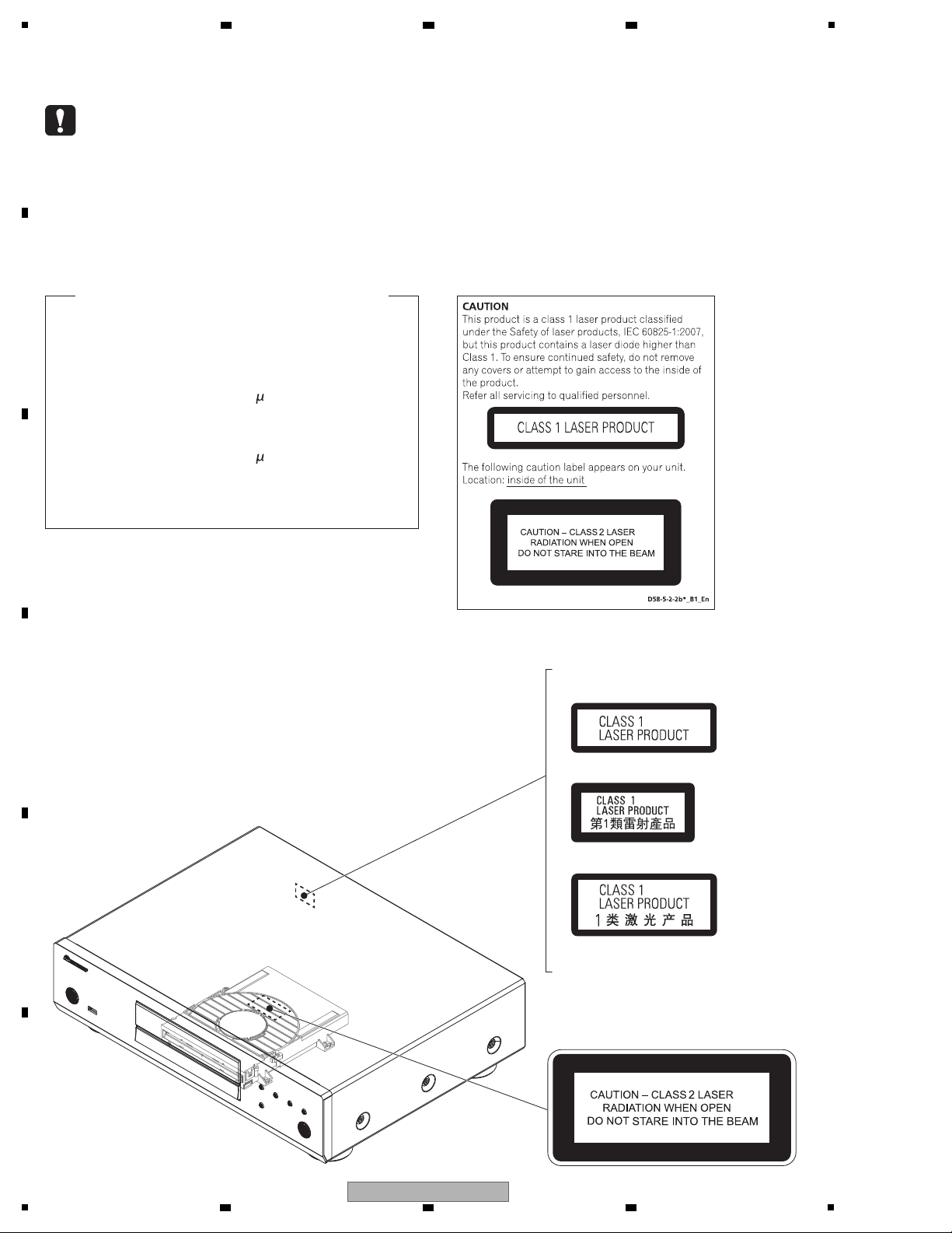
LABEL CHECK
BDP-LX58/AXQ5
(Printed on the Back chassis)
BDP-LX58-K, S/YXE8
BDP-LX58/LXE
BDP-LX58/FXE
The following caution label appears on
your unit.
Location: inside of the unit
Laser Pickup specifications and Laser characteristics
BD Wave length : 405 nm
Operating output : 1.16 mW CW, Class 1
Maximum output : Class 2 (under fault condition)
DVD Wave length : 657 nm
Operating output : 178 W CW, Class 1
Maximum output : Class 1 (under fault condition)
CD Wave length : 785 nm
Operating output : 174 W CW, Class 1
Maximum output : Class 1 (under fault condition)
2 3 4
SAFETY INFORMATION
A
B
C
D
E
F
2
1
2 3 4
BDP-LX58-K

5
6 7 8
CONTENTS
SAFETY INFORMATION.......................................................................................................................................................... 2
1. SERVICE PRECAUTIONS ....................................................................................................................................................4
1.1 NOTES ON SOLDERING............................................................................................................................................... 4
2. SPECIFICATIONS .................................................................................................................................................................5
3. BASIC ITEMS FOR SERVICE ..............................................................................................................................................6
3.1 CHECK POINTS AFTER SERVICING ........................................................................................................................... 6
3.2 JIGS LIST .......................................................................................................................................................................6
3.3 PCB LOCATIONS ........................................................................................................................................................... 7
4. BLOCK DIAGRAM ................................................................................................................................................................8
4.1 OVERALL WIRING DIAGRAM .......................................................................................................................................8
4.2 OVERALL BLOCK DIAGRAM....................................................................................................................................... 10
4.3 POWER SUPPLY BLOCK DIAGRAM........................................................................................................................... 12
5. DIAGNOSIS ........................................................................................................................................................................ 14
5.1 TROUBLESHOOTING.................................................................................................................................................. 14
6. SERVICE MODE................................................................................................................................................................. 20
6.1 SERVICE MODE .......................................................................................................................................................... 20
7. DISASSEMBLY ................................................................................................................................................................... 27
8. EACH SETTING AND ADJUSTMENT................................................................................................................................ 36
8.1 NECESSARY ITEMS FOR ADJUSTMENTS................................................................................................................ 36
8.2 UPDATING OF THE FIRMWARE ................................................................................................................................. 37
8.3 HOW TO READ OUT BARCODE DATA USING A USB MEMORY DEVICE................................................................37
8.4 HOW TO WRITE BARCODE DATA USING A USB MEMORY DEVICE.......................................................................38
9. EXPLODED VIEWS AND PARTS LIST...............................................................................................................................40
9.1 PACKING SECTION ..................................................................................................................................................... 40
9.2 EXTERIOR SECTION .................................................................................................................................................. 42
9.3 BD LOADER SECTION................................................................................................................................................ 45
10. SCHEMATIC DIAGRAM .................................................................................................................................................... 46
10.1 MAIN BOARD ASSY (1/10)........................................................................................................................................ 46
10.2 MAIN BOARD ASSY (2/10)........................................................................................................................................ 48
AIN BOARD ASSY (3/10) ........................................................................................................................................ 50
10.3 M
10.4 MAIN BOARD ASSY (4/10)........................................................................................................................................ 52
10.5 MAIN BOARD ASSY (5/10)........................................................................................................................................ 54
10.6 MAIN BOARD ASSY (6/10)........................................................................................................................................ 56
10.7 MAIN BOARD ASSY (7/10)........................................................................................................................................ 58
10.8 MAIN BOARD ASSY (8/10)........................................................................................................................................ 60
10.9 MAIN BOARD ASSY (9/10)........................................................................................................................................ 62
10.10 MAIN BOARD ASSY (10/10) ....................................................................................................................................64
10.11 AUDIO BOARD ASSY ..............................................................................................................................................66
10.12 FRONT CONTROL BOARD ASSY........................................................................................................................... 68
10.13 SWITCH, LED and RS BOARD ASSYS................................................................................................................... 70
10.14 RELAY BOARD ASSY.............................................................................................................................................. 71
0.15 POWER BOARD ASSY............................................................................................................................................72
1
10.16 WAVEFORMS...........................................................................................................................................................74
11. PCB CONNECTION DIAGRAM........................................................................................................................................76
11.1 MAIN BOARD ASSY .................................................................................................................................................. 76
11.2 AUDIO BOARD ASSY ................................................................................................................................................80
11.3 FRONT CONTROL, SWITCH, LED and RS BOARD ASSYS .................................................................................... 82
11.4 RELAY BOARD ASSY................................................................................................................................................ 86
11.5 POWER BOARD ASSY..............................................................................................................................................88
12. PCB PARTS LIST .............................................................................................................................................................. 90
A
B
C
D
E
F
BDP-LX58-K
5
6 7 8
3

1
• For environmental protection, lead-free solder is used on the printed circuit boards mounted in this unit.
Be sure to use lead-free solder and a soldering iron that can meet specifications for use with lead-free solders for repairs
accompanied by reworking of soldering.
• Compared with conventional eutectic solders, lead-free solders have higher melting points, by approximately 40 ºC.
Therefore, for lead-free soldering, the tip temperature of a soldering iron must be set to around 373 ºC in general, although
the temperature depends on the heat capacity of the PC board on which reworking is required and the weight of the tip of
the soldering iron.
Do NOT use a soldering iron whose tip temperature cannot be controlled.
Compared with eutectic solders, lead-free solders have higher bond strengths but slower wetting times and higher melting
temperatures (hard to melt/easy to harden).
The following lead-free solders are available as service parts:
• Parts numbers of lead-free solder:
GYP1006 1.0 in dia.
GYP1007 0.6 in dia.
GYP1008 0.3 in dia.
2 3 4
1. SERVICE PRECAUTIONS
1.1 NOTES ON SOLDERING
A
B
C
D
E
F
4
1
2 3 4
BDP-LX58-K
5
• Remote control x 1
(YXE8, LXE, FXE: VXX3392)
(AXQ5: VXX3393)
• AAA 700 size manganese batteries x 2
• Power cord
(YXE8, LXE: ADG7123)
(FXE: ADG7120)
(AXQ5: ADG7122)
• Warranty card (YXE8, AXQ5 only)
• Software license notice
(YXE8, LXE, FXE: 70-PONEER-LCSB4)
(AXQ5: 70-PONEER-LCSB5)
• Operating instructions
(YXE8: 72-BDPL88-GBRB1, 72-BDPL88-EURB1)
(LXE: 72-BDPL88-GBRB1, 72-BDPL58-TWNB1)
(FXE: 72-BDPL58-TWNB1)
(AXQ5: 72-BDPL58-CHNB1)
• Software update notice
(YXE8, LXE, FXE: 70-BDPX58-SHTB2)
(AXQ5: 70-BDPX58-SHTB1)
• Taiwan label (FXE only)
(71-BDPL88-FXEB1)
Accessories
AC 220 V to 240 V (YXE, LXE, AXQ5)
AC 110 V (FXE)
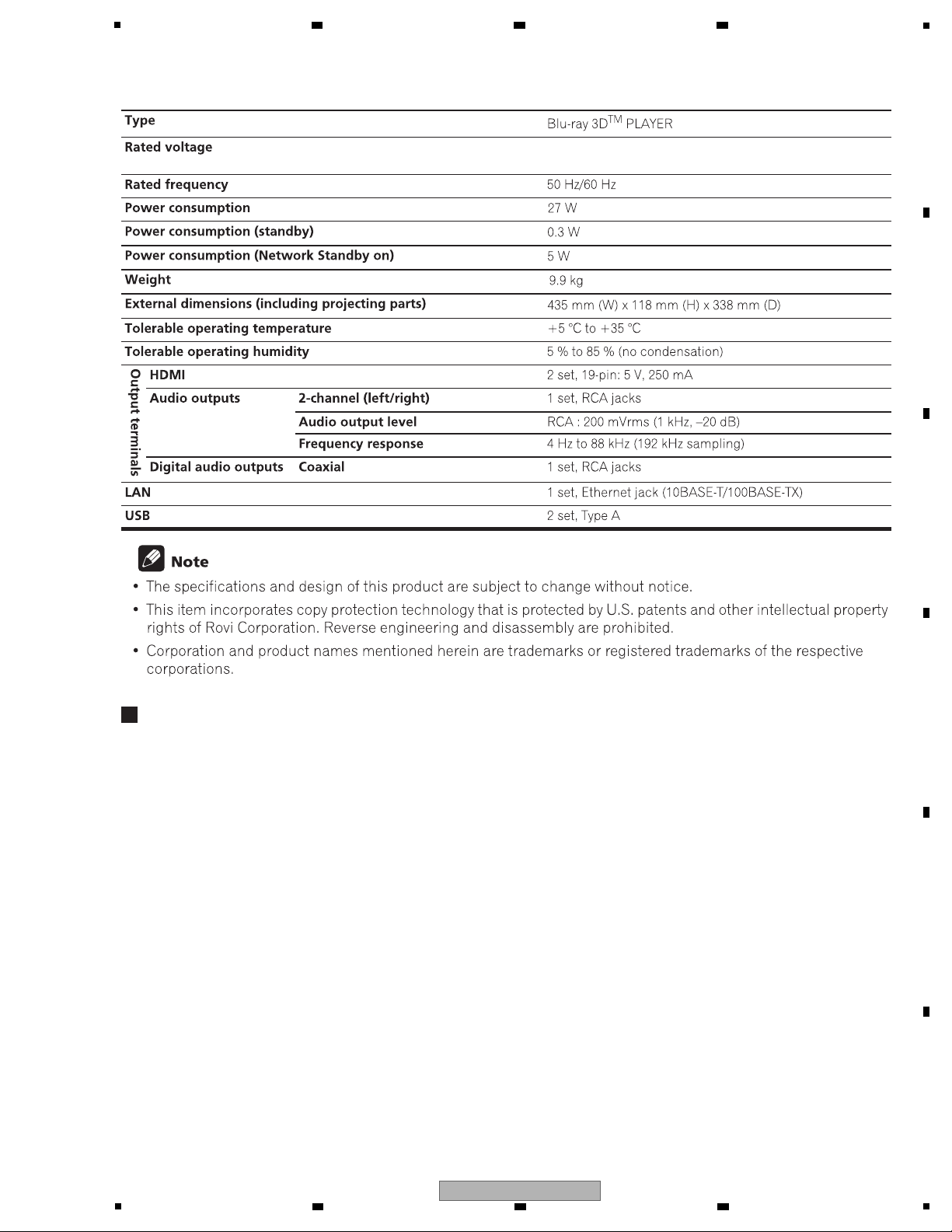
2. SPECIFICATIONS
6 7 8
A
B
C
D
E
5
BDP-LX58-K
6 7 8
F
5
1
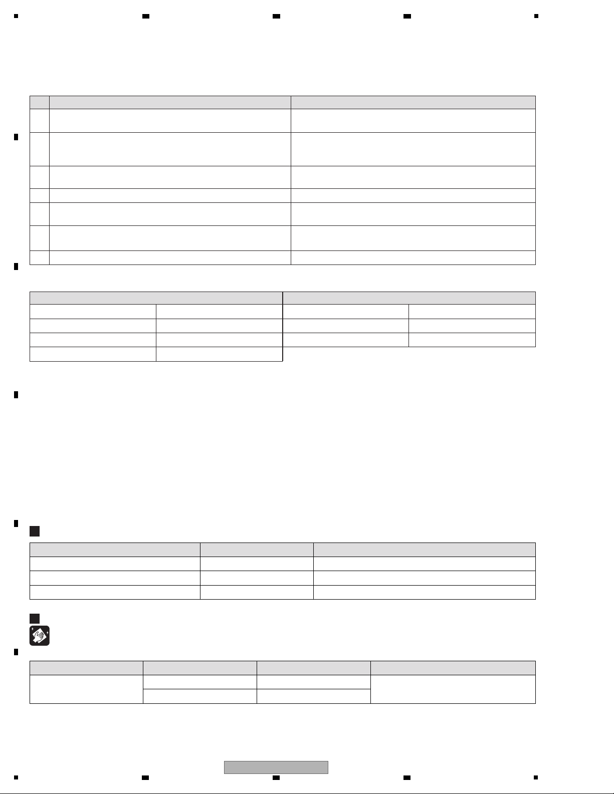
7 Check the appearance of the product.
No scratches or dirt on its appearance after receiving it for service.
1 Confirm the firmware version on Test Mode. The version of the firmware must be latest.
Update firmware to the latest one, if it is not the latest.
2 Confirm whether the customer complain has been solved.
If the customer complain occurs with the specific disc, use it for
the operation check.
The customer complain must not be reappeared.
Video, audio and operations must be normal.
6 Play back a BD.
(Menu operation, Title/chapter search)
Video, audio and operations must be normal.
3 Play back a CD.
(track search)
Audio and operations must be normal.
4 Play back a SACD. Audio and operations must be normal.
5 Play back a DVD.
(Menu operation, Title/chapter search)
Video, audio and operations must be normal.
Distortion
Noise
Volume too low
Volume too high
Volume fluctuating
Sound interrupted
See the table below for the items to be checked regarding video and audio.
No. Procedures
Item to be checked regarding audio
Block noise
Horizontal noise
Dot noise
Disturbed image (video jumpiness)
Too dark
Too bright
Color disappearance
Mottled color
Item to be checked regarding video
Check points
Items to be checked after servicing
To keep the product quality after servicing, confirm recommended check points shown below.
Position to be cleaned Name Remarks
Pickup lens
Cleaning liquied
Refer to "7. DISASSEMBLY".
Part No.
GEM1004
Cleaning paper GED-008
Cleaning
Before shipping out the product, be sure to clean the following positions by using the prescribed cleaning tools.
Jigs List
DVD Test Disc (DVD-Video) GGV1025 Check of DVD-Video
BD-ROM Test Disc GGV1350 Check of BD-ROM
BD-ROM Test Disc (One layer type) GGV1368 For Adjustment
Jig Name Part No.
Purpose of use / Remarks
2 3 4
3. BASIC ITEMS FOR SERVICE
3.1 CHECK POINTS AFTER SERVICING
A
B
C
D
3.2 JIGS LIST
E
F
6
1
2 3 4
BDP-LX58-K
5
1..MAIN BOARD ASSY (YXE8) 08-BDLX58-MA1/Y
1..MAIN BOARD ASSY (LXE) 08-BDLX58-MA2
1..MAIN BOARD ASSY (FXE) 08-BDLX58-MA2/F
1..MAIN BOARD ASSY (AXQ5) 08-BDLX58-MA4
1..AUDIO BOARD ASSY 08-BDLX58-AD1
1..FRONT CONTROL BOARD ASSY 08-BDLX58-FV0
1..SWITCH BOARD ASSY 08-BDLX58-SW0
1..LED BOARD ASSY 08-BDLX58-LE0
1..LED BOARD ASSY 08-BDLX58-LE1
1..RS BOARD ASSY 08-BDLX58-RS0
1..RELAY BOARD ASSY 08-BDLX58-RL0
1..POWER BOARD ASSY 08-BDLX58-PW0
BD LOADER 08-BDLX58-SH0
Mark No. Description Part No. Mark No. Description Part No.
LIST OF ASSEMBLIES
NOTES: - Parts marked by “NSP” are generally unavailable because they are not in our Master Spare Parts List.
-
The > mark found on some component parts indicates the importance of the safety factor of the part.
Therefore, when replacing, be sure to use parts of identical designation.
G
RS BOARD ASSY
I
POWER BOARD ASSY
D
SWITCH
BOARD ASSY
LED BOARD ASSY
H
RELAY BOARD
ASSY
A
MAIN BOARD ASSY
B
AUDIO BOARD ASSY
BD LOADER
C
FRONT CONTROL
BOARD ASSY
F
LED BOARD ASSY
E
3.3 PCB LOCATIONS
6 7 8
A
B
C
5
6 7 8
BDP-LX58-K
D
E
F
7
1
11pin
BtoB
9pin
BtoB
Taiko 11pin
TWG-P11X
Socket (Female)
Taiko 11pin
TWG-P11P
Plug (Male)
Taiko 9pin
TWG-P9X
Socket (Female)
Taiko 9pin
TWG-P9P
Plug (Male)
V+5.6_EV
V+5.6_EV
GNDD
GNDD
+14V
+14V
GNDD
GND
4pin
FFC
EV.5V
232C_RXD
232C_TXD
GND
PCON
V+5.6_EV
V+5.6_EV
V+5.6_EV
GNDD
GNDD
+12V
GND_M
GNDD
GNDD
-14V
-14V
CN3023
CN504 CN1509
CN1505
CN501
AC IN
CN503
CN3007
CN3005
CN3004
XP6
45P FFC
0.5mm pitch
9P FFC
1mm pitch
4P wire
2mm pitch
TPIC_V
TPIC_W
MGND
TPIC_B+
TPIC_B-
TPIC_A+
TPIC_A-
TPIC_COMMON
TPIC_U
MGND
TPIC_TRAYIN
TPIC_LOAD-
TPIC_LOAD+
TPIC_CO_A+
TPIC_CO_A-
TPIC_CO_B+
TPIC_CO_B-
HAVC
AUX1
GND
INC
INA
IND
INF
INH
ING
VCC_PDIC
INE
INB
GND
GND
RFO-
FEGIO5
FEGAINSW1
RFO+
LDD_CLK
LDD_SDIO
FEGIO7
LDD_SEN
GND
VCC_LD
VCC_LD
VCC_BDLD
VCC_BDLD
GND
GND
TPIC_FR+
TPIC_FR-
TPIC_TR+
TPIC_TR-
TPIC_TL+
TPIC_TL-
FPDODVD
GND
GND
GND
GND
GND
1
2
3
4
5
6
7
8
9
1
2
3
4
5
6
7
8
9
10
11
12
13
14
15
16
17
18
19
20
21
22
23
24
25
26
27
28
29
30
31
32
33
34
35
36
37
38
39
40
41
42
43
44
45
1
2
3
4
MAIN BOARD ASSY
(YXE8: 08-BDLX58-MA1/Y
(LXE: 08-BDLX58-MA2)
(FXE: 08-BDLX58-MA2/F)
(AXQ5: 08-BDLX58-MA4)
A
POWER BOARD ASSY
(08-BDLX58-PW0)
BD LOADER
(08-BDLX58-SH0)
I
RS BOARD ASSY
(08-BDLX58-RS0)
G
A A
1/10 - 10/10
-
When ordering service parts, be sure to refer to "EXPLODED VIEWS and PARTS
LIST" or "PCB PARTS LIST".
-
The > mark found on some component parts indicates the impor tance of the
safety factor of the part.
Therefore, when replacing, be sure to use parts of identical designation.
2 3 4
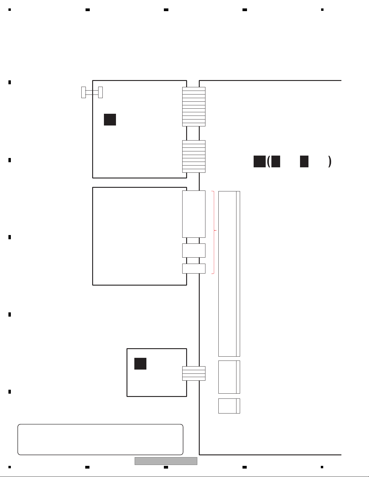
4. BLOCK DIAGRAM
4.1 OVERALL WIRING DIAGRAM
A
B
C
D
E
F
8
1
2 3 4
BDP-LX58-K
Taiko 11pin
TWG-P11X
Socket (Female)
Taiko 11pin
TWG-P11P
Plug (Male)
Taiko 13pin
TWG-P13X
Socket (Female)
Taiko 13pin
TWG-P13P
Plug (Male)
V+14(14V)
V+14(14V)
GND_A
GND_A
GND_A
V-14A(-14V)
V-14A(-14V)
GND_AA
GND_AA
V+5(5.6V)
V+5(5.6V)
11pin
BtoB
RY
AMUTE
I2CSDA
I2CSCL
DACRST
GNDD
DATA/DSDFL
GNDD
DATA/DSDFR
GNDD
BCK
GNDD
LRCK/DSDFR
13pin
BtoB
IRISO 20pin
IMSA-9111S-20L
PH 12pin
PH 5Pin PH 5Pin
PH 4Pin PH 4Pin
PH 12pin
IRISO 3pin
IMSA-9120B
IRISO 3pin
IMSA-9120S
IRISO 20pin
IMSA-9111B-20
EV+5V
GND
+12V
+12V
GND
VSTB
VDATA
VCLK
GND
IR
GND
OPEN
POWER
POWERON LED
GND
GND
VCC
USB D+
USB D-
GND
20pin
BtoB
5pin
Wire
4pin
Wire
VCC
GND
+12V_D
GND
12V
AC1
AC2
EN-24V
GND
+12V_D
GND
VFD
DC-DC
VSTB
VDATA
VCLK
GND
IR
GND
GND
VCC
POWERLED
POWER_K
GND
GND
VCC_USB
GND
USBP0
USBM0
GND
XP2
XS1
XP1CN3003
XP2
XP3
XP4
XS1
XS2
CN5000
CN5001CN1511
CN1506
XP1 XP4
XP3
LED1
GND
IRISO 3pin
IMSA-9120B
IRISO 3pin
IMSA-9120S
GND
LED2
GND
AUDIO BOARD ASSY
(08-BDLX58-AD1)
B
FRONT CONTROL
BOARD ASSY
(08-BDLX58-FV0)
C
SWITCH
BOARD ASSY
(08-BDLX58-SW0)
D
LED BOARD ASSY
(08-BDLX58-LE0)
E
LED BOARD ASSY
(08-BDLX58-LE1)
F
RELAY BOARD ASSY
(08-BDLX58-RL0)
H
10/10
5
6 7 8
A
B
C
5
BDP-LX58-K
6 7 8
D
E
F
9
1
MPEG Decoder
(MTK)
IC3001
MT8560
Motor Driver
IC3409
TPIC2050
TC74VHC157FTS1
DDR3_2Gb
IC3002
NT5CB128M16FP-DI
DDR3_2Gb
IC3003
NT5CB128M16FP-DI
NAND Flash_2Gb
IC3008
MT29F2G08ABAEAWP
Event CPU
IC4001
R5F100MHAF
FRONT
USB
VFD Driver
U1
PT6302
VFD
IR
AC IN
USB D+/D-
IR
I2S / DSD
5.6V_EV
VCXO
X3001
27 MHz
DSD
I2S
SELECTOR
IC1501
±14V
I2C (SCL_1/SDA_1)
TMDS
UART (Tx/Rx)
I
POWER BOARD ASSY
C
FRONT CONTROL
BOARD ASSY
H
RELAY
BOARD ASSY
D
SWITCH
BOARD ASSY
BD LOADER
2 3 4
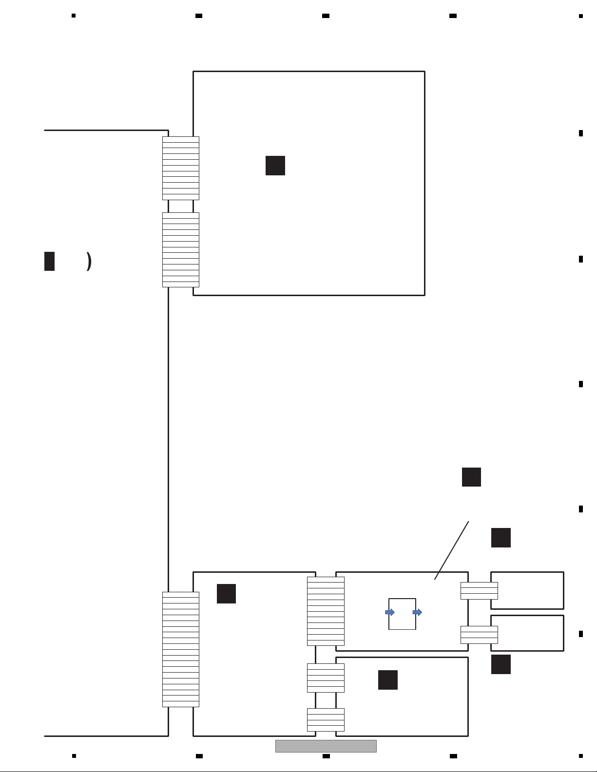
4.2 OVERALL BLOCK DIAGRAM
A
B
C
D
E
F
10
1
2 3 4
BDP-LX58-K
5
DAC
IC200
ES9011S
Vref
IC5007 IC5005
IC5009
IC5010
Vref
I/V
I/V
LPF
IC5008
IC5011
LPF
X2000
80 MHz
UNBAL-Lch OUT
UNBAL-Rch OUT
HDMI Transmitter
(Pana)
IC1602
MN8647771
SCALERIC
(Marvel)
IC1204
88DE2750
DDR2
IC1212
NT5TU32M16DG-AC
Sub MICON
(SH2)
IC101
R5S726B0D216FP
X101
12 MHz
Gate Array
IC603
PE7008A-K
Event CPU
IC4001
R5F100MHAFA
COAXIAL
REAR
HDMI (MAIN)
HDMI
LAN
ZERO SIGNAL
RS-232C
SPDIF
HEX INVERTERS
IC3901
SN74AHCU04PWR
SPDIF
USB D+/D-
Tx/Rx
UART Tx/Rx
X602
36.864 MHz
X1602
27 MHz
X1201
20 MHz
I2S / DSD
SPI
VIDEO DATA
TMDS
TMDS
I2C (DDC)
I2C (DDC)
I2C
(AUDIOSCL/AUDIOSDA)
I2C
(HDSCL/HDSDA)
TMDS
SPI
RT (Tx/Rx)
SDRAM
IC102
M12L128168A-5TG2N
MX25L6435EM2I-10G
SERIAL FLASH
IC103
A
MAIN BOARD ASSY
B
AUDIO BOARD ASSY
G
RS BOARD
ASSY
6 7 8
A
B
C
D
5
BDP-LX58-K
6 7 8
E
F
11
1
U505
BAJ2DD0WT
+12V
V+5.6_EV
IC5000
NJM2880U1-33
V+3R3_D
V+14V
V-14V
IC2402
S-1172B12-E6
V+1R2_D
DAC
IC5006
ES9011S
V+3R3_D
IC2401
NJM78M56FA
IC2405
NJM2872BF33
V+3R3_A
EN
from
MTK
DVCPOW
from
Eve-COM
Vref
IC5007
IC5010
I/V
IC5005
IC5009
LPF
Co
Ev.5.6V
DVCPOW
12V
IC5008
IC5011
V+12_AR / V+12_AL
V-12_AR / V-12_AL
AC IN
IC5003
NJM7812FA
IC5003
NJM7812FA
I
POWER BOARD ASSY
B
AUDIO BOARD ASSY
2 3 4
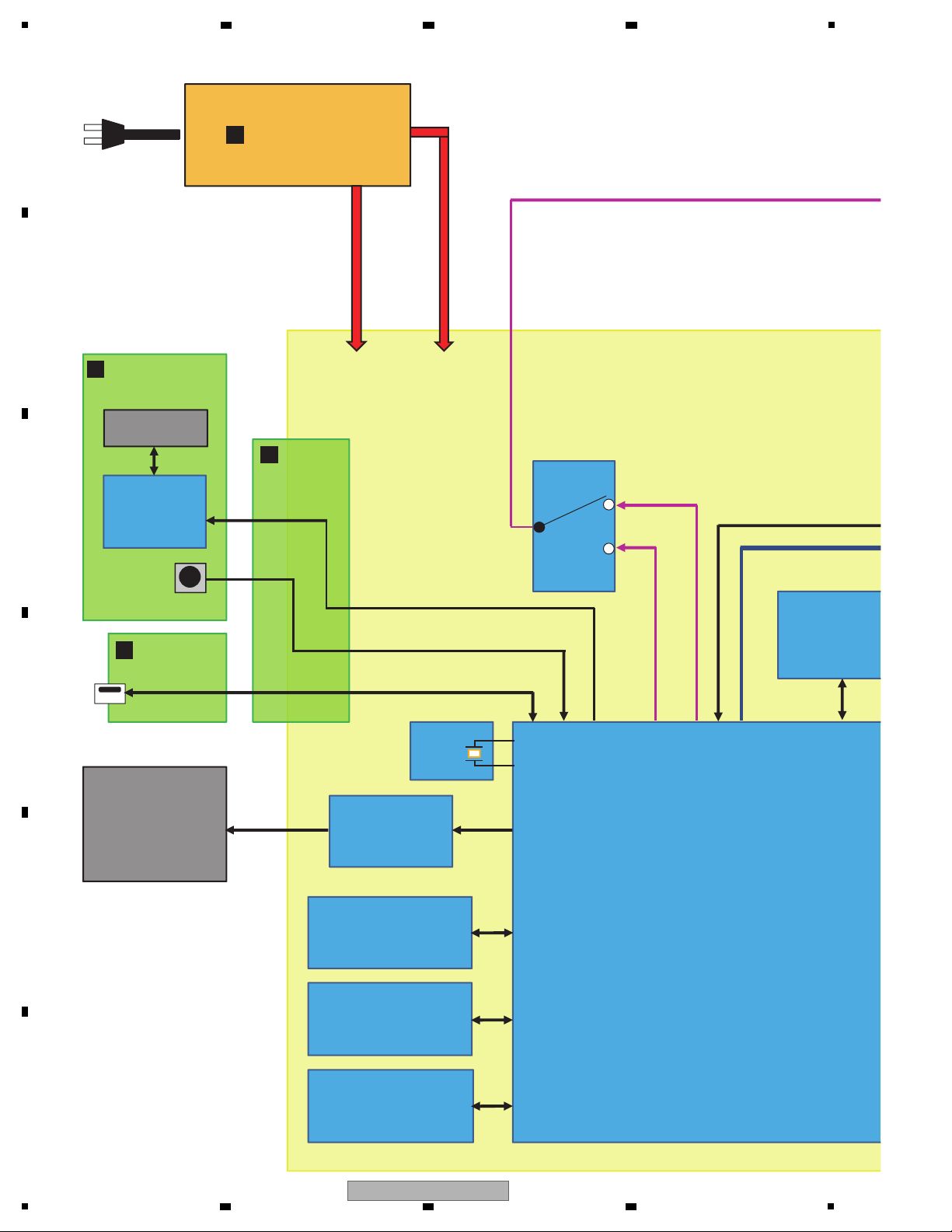
4.3 POWER SUPPLY BLOCK DIAGRAM
A
B
C
D
E
F
12
1
2 3 4
BDP-LX58-K
5.6V -> 5V 2A
V+1R8HHH
DVCPOW
DVCPOW
DVCPOW
V+3R3_MV
V+1R8_SC
V+1_SC
V+5_EV
FL
FL Driver
DIRECT LED
FL LED
KEY
KEY MCU
IR
POWER LED
FRONT USB
EN
from
MTK
DVCPOW
from
Eve-COM
IC9101
LDO
S-1112B33
MT8560
3.3V_STBY
3.3V
DDRVCCIO
DDR_VREF
V+12V_D
12V -> 8V
Variable type
IC101
RS5S726B0D216FP
(SH2)
SDRAM
IC1602
HDMI Tx
MN864777
(Pana)
Flash
IC9403
1.1V DCDC con
MM3542BF
Control another in Video QDEO
IC9404
1.8V LDO
Ripple Blocker
MIC94325YMT
IC9402
1V LDO
S-1172B10
IC9406
5V LDO
S-1170B50
IC9532
3.3V LDO
S-1172B33-E6
V+3R3_AUD
IC9408
2.5V LDO
Ripple Blocker
MIC94325YMT
VPPOW
3.3V
Ev.5.6V
DVCPOW
5V
V+5_VCC
V+5_USBFR
V+3R3_EM
V+1R25_SH2
V+1R1_HD
VDD11
AVDD11
AVDD11
V+3R3_HHH
3.3V
V+3R3_HHH
1.8V
USB Rear
TPIC2050
Driver IC
IC9103 LDO
NJM2830-8
200mA
IC9104 LDO
BA00DD0WHFP
5V
High Side SW
IC9515
1.25V LDO
Ripple Blocker
MIC94325YMT
IC9527
DCDC
BD9328
IC9528
DCDC
BD9329
IC9531
5V LDO
S-1170B50
JA1601
HDMI OUT1 5V
V+5_HD OTHER
IC1204
VIDEO
PROCESSOR
88DE2750
IC1212
DDR2 for
Scaler
Event
CPU
RS232C
Gate Array
Digital Audio
OUT
JA160x
HDMI OUT2/Z 5V
IC9525
LDO
S-1172B33
DDR3 for
SOC
1G
DDR3 for
SOC
2G
1.2V
1.5V
12V
IC9102
LDO
S-1172B33
IC9530
DCDC
BD9328
IC9529
DCDC
BD9328
A
MAIN BOARD ASSY
C
FRONT CONTROL
BOARD ASSY
H
RELAY
BOARD ASSY
D
SWITCH
BOARD ASSY
5
5
6 7 8
BDP-LX58-K
6 7 8
A
B
C
D
E
F
13
1
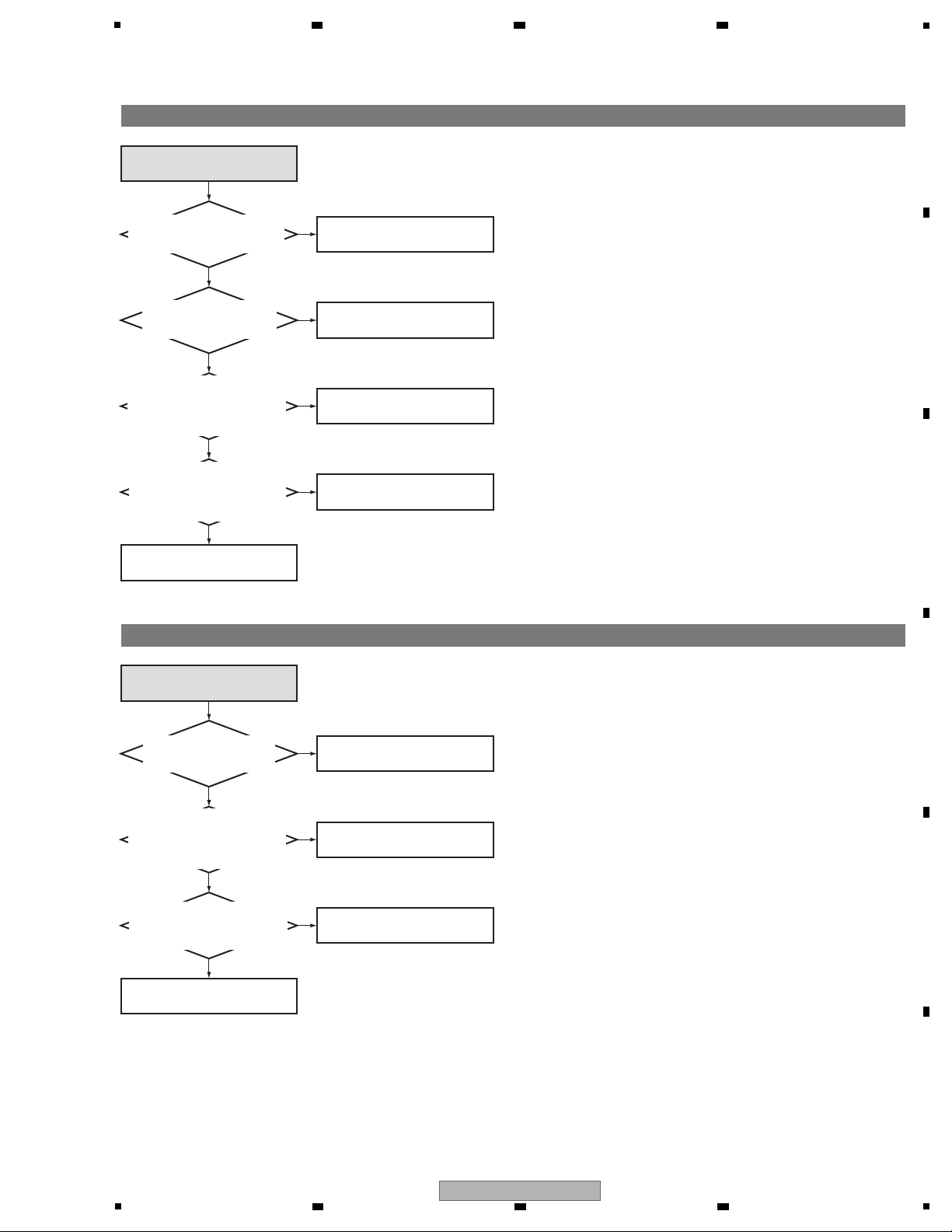
No power
Are the Power buttons on both
the remote control unit and
the main unit disabled?
Is the voltage at Pins 3, 4,
and 5 of CN1505 on the MAIN
BOARD Assy 5.6 V?
No
Ye s
Ye s
No power
Go to the flowcharts for "The buttons
do not function" and "The remote
control unit does not function."
No
Replace the POWER BOARD
Assy.
Replace the MAIN BOARD Assy.
No display on the VFD
Is the unit set to
FL OFF mode?
Are the voltages at Pin 1 of XP
on the RELAY BOARD Assy
5 V and at Pins 3 and 4 12 V?
Is the amount of solder at L1
on the FRONT CONTROL
BOARD Assy appropriate?
Is the voltage at the negative
electrode of CE3 on the FRONT
CONTROL BOARD Assy –24 V?
Is the soldering at the FL
display, U1, and U2 on the
FRONT CONTROL BOARD
Assy appropriate?
Are the voltages at Pin 1 of
CN3003 on the MAIN
BOARD Assy 5 V and at
Pins 2 and 3 12 V?
No
Ye s
Ye s
Ye s
Ye s
Ye s
Ye s
No display on the VFD
No
No
No
Press the DIMMER button on the
remote control unit to cancel
FL OFF mode.
Add solder to L1.
No
Replace the MAIN BOARD Assy.
Replace the RELAY BOARD Assy.
Replace the FRONT CONTROL
BOARD Assy.
Replace the FRONT CONTROL
BOARD Assy.
No
Resolder the parts whose solder
was inappropriate.
5. DIAGNOSIS
5.1 TROUBLESHOOTING
A
2 3 4
B
C
D
E
F
14
1
BDP-LX58-K
2 3 4
5
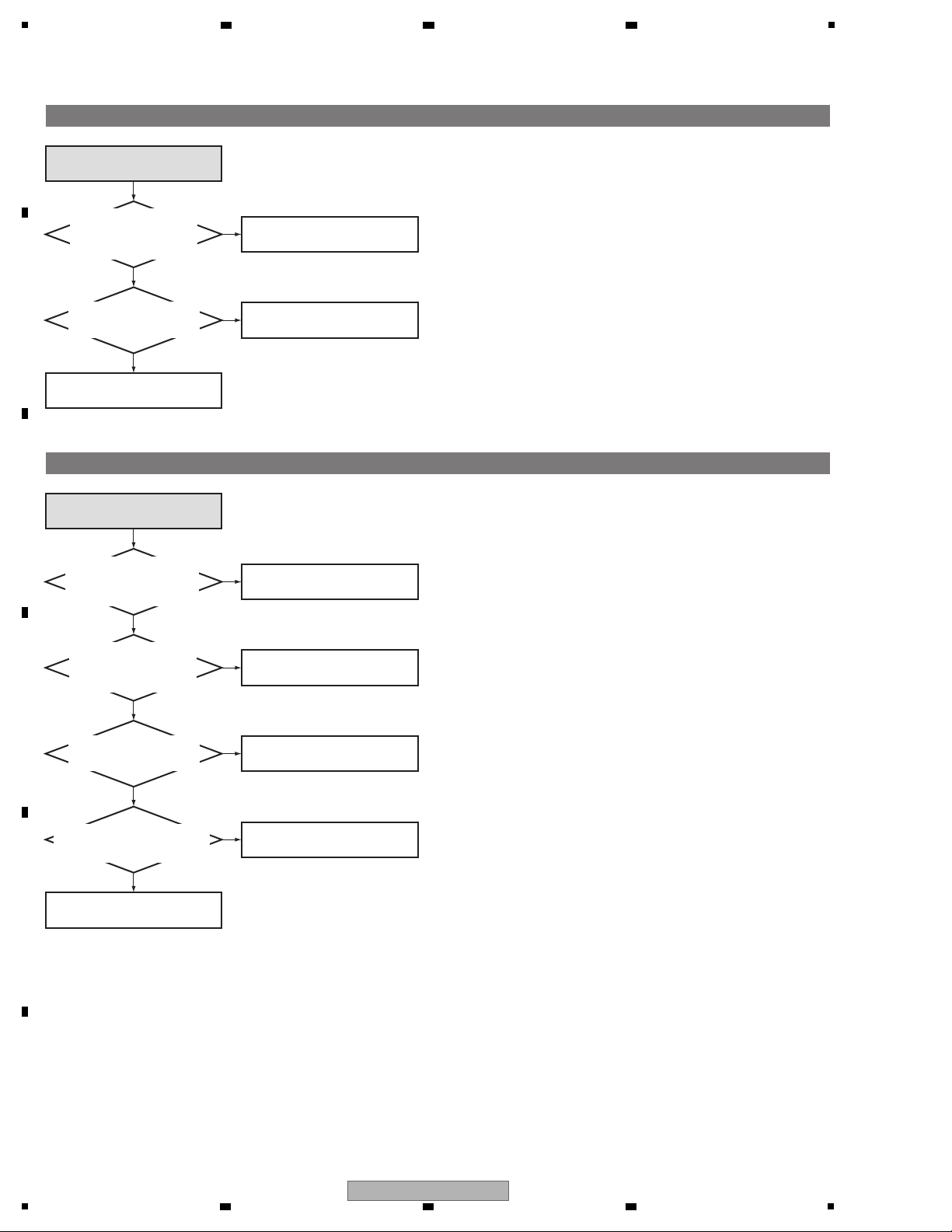
The buttons do not function.
Is the soldering at SW1 to SW6
on the FRONT CONTROL
BOARD Assy appropriate?
No
Ye s
The buttons do not function.
Repair inappropriate solder.
Is the soldering at U2 on
the FRONT CONTROL
BOARD Assy appropriate?
No
Ye s
Repair inappropriate solder.
Is the waveform of a signal from the
remote control unit observed at Pin 10
of XS1 on the FRONT CONTROL
BOARD Assy when any button on the
remote control unit is pressed?
No
Ye s
Replace the FRONT CONTROL
BOARD Assy.
Is the waveform of a signal from the
remote control unit observed at Pin 10
of XS1 on the FRONT CONTROL
BOARD Assy when the remote
control unit is used? (Waveform
1
)
No
Replace the FRONT CONTROL
BOARD Assy.
Is the waveform of a signal from the
remote control unit observed at Pin 10
of CN3003 on the MAIN BOARD Assy
when any button on the remote
control unit is pressed?
No
Ye s
Replace the RELAY BOARD Assy.
Replace the MAIN BOARD Assy.
Is the waveform of a signal from the
remote control unit observed at Pin 10
of CN3003 on the MAIN BOARD Assy
when the remote control unit is used?
No
Ye s
Replace the RELAY BOARD Assy.
Replace the MAIN BOARD Assy.
The remote control unit does not function.
Is the remaining battery
level of the remote control
unit enough?
No
Ye s
Ye s
The remote control unit does not
function.
Replace the battery of the remote
control unit with a new one.
6 7 8
A
B
C
D
5
BDP-LX58-K
6 7 8
E
F
15
1
The disc tray does not open.
Are the cables from the
BD LOADER properly
connected to CN3004 on
the MAIN BOARD Assy?
No
Ye s
The disc tray does not open.
Properly connect the cables.
Is the soldering at IC3409
on the MAIN BOARD Assy
appropriate?
Is the soldering at IC3409
on the MAIN BOARD Assy
appropriate?
No
Ye s
Repair inappropriate solder.
Replace the BD LOADER.
Is the 45-pin FFC from the
BD LOADER properly
connected to CN3007 on
the MAIN BOARD Assy?
No
Ye s
Properly connect the cables.
Is the 9-pin FFC from the
BD LOADER properly
connected to CN3005 on
the MAIN BOARD Assy?
No
Ye s
Properly connect the cables.
No
Ye s
Repair inappropriate solder.
Is the voltage at Pin 4 of IC9103
on the MAIN BOARD Assy
8 V?
No
Ye s
Replace the MAIN BOARD Assy.
Replace the BD LOADER.
The unit does not recognize a disc.
The unit does not recognize a disc.
A
2 3 4
B
C
D
E
F
16
1
BDP-LX58-K
2 3 4
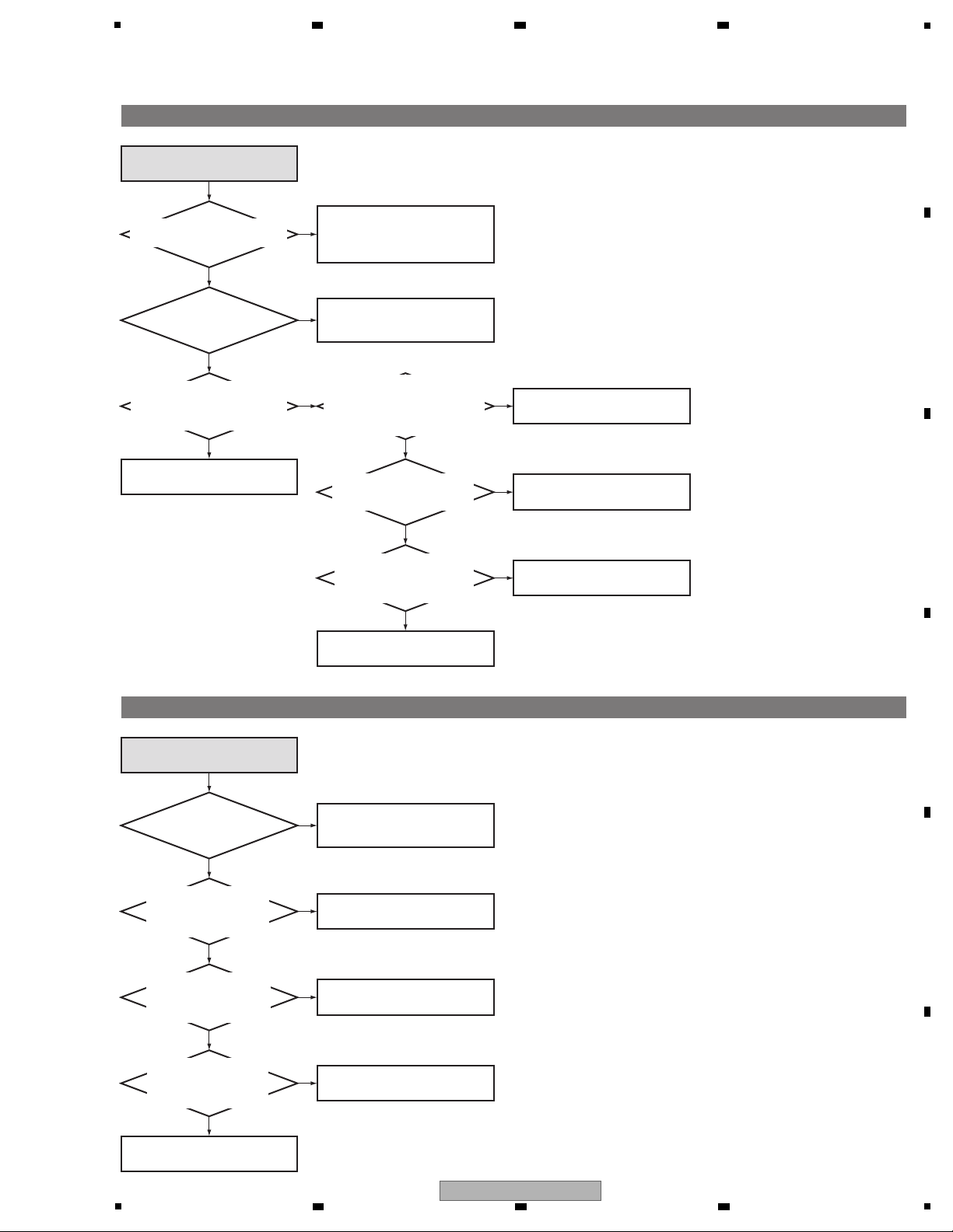
No HDMI output
Does the connected TV support
the output resolution of this unit?
No
Ye s
No HDMI output
Select an appropriate resolution,
using the Resolution Select button
on the remote control unit.
(AUTO recommended)
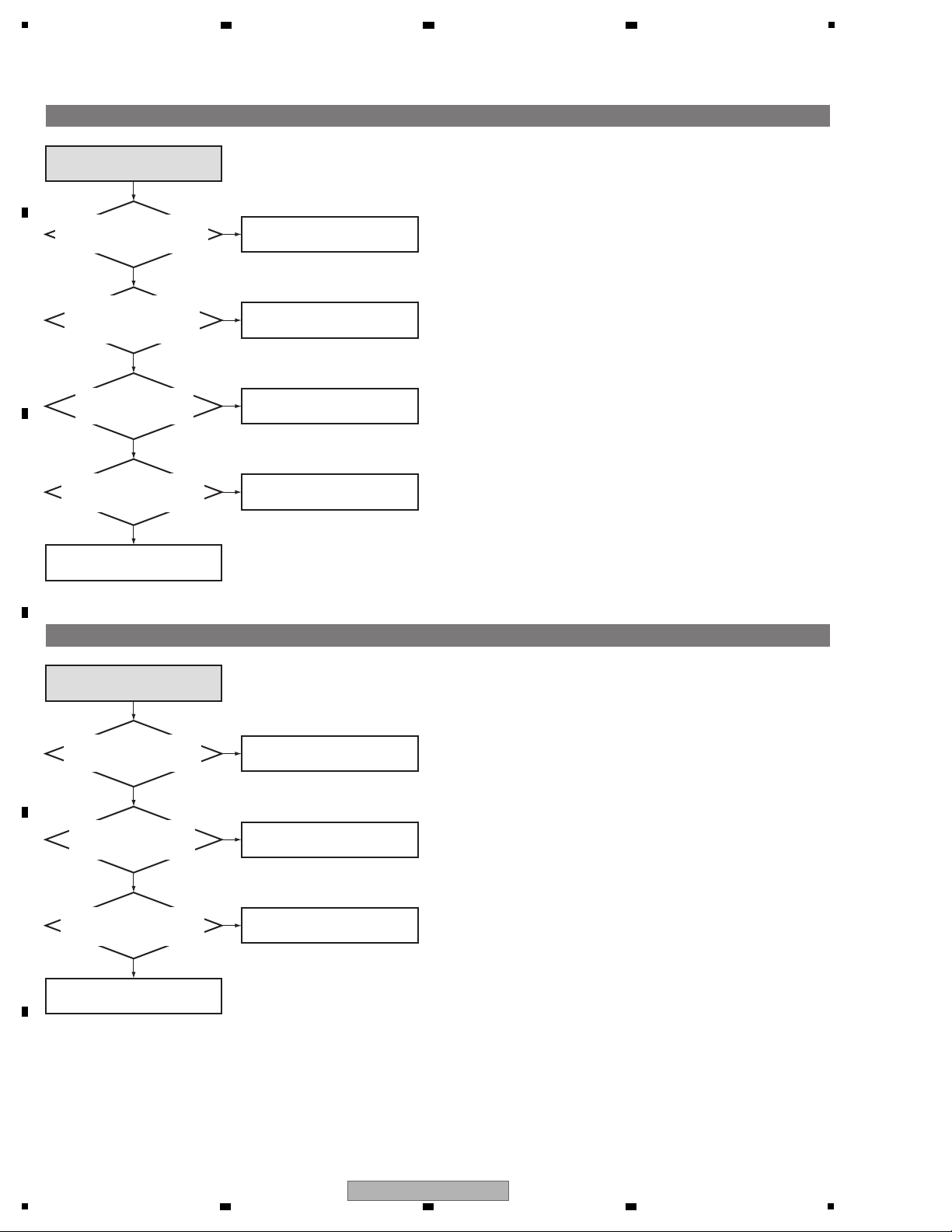
No digital (COAX) output
Is the digital output setting
enabled?
No
No digital (COAX) output
Select "Initial Setup," "Audio Output,"
then "Digital Output," in that order,
then select an option other than OFF.
Is the unit set to Direct OFF
mode?
Are the voltages at C9450 on
the MAIN BOARD Assy
1.2 V and at C9105 3.3 V?
Is a 27-MHz oscillation
signal output from X1602 on
the MAIN BOARD Assy?
(Waveforms
2, 3
)
Is the indication HDMI1 or HDMI2 on
the FL display lit when the HDMI cable
is connected to the corresponding
connector of the unit?
Is the soldering at IC1602, JA1601,
JA1603, L1609, L1610, L1611, L1612,
L1638, L1639, L1640, and L1641
on the MAIN BOARD Assy
appropriate?
No
No
Ye s
Ye s
Ye s
Set the unit to Direct OFF mode,
using the Direct button on the
remote control unit.
Replace the MAIN BOARD Assy.
Replace the MAIN BOARD Assy.
Replace the MAIN BOARD Assy.
Ye s
Is there an SPDIF signal
at R3004 on the
MAIN BOARD Assy?
(Waveform 5)
Ye s
Is there an SPDIF signal
at Pin 8 of IC3901 on the
MAIN BOARD Assy?
(Waveform 4)
Ye s
Ye s
No
Repair inappropriate solder.
No
Check the soldering at IC9527
and IC9403.
No
No
Check the soldering at IC3901.
No
Is there an SPDIF signal
at R3906 on the
MAIN BOARD Assy?
(Waveform 6)
Ye s
Ye s
Check the soldering at VL3901.
Check the soldering at JA3901.
No
Check the soldering at X1602.
5
6 7 8
A
B
C
5
BDP-LX58-K
6 7 8
D
E
F
17
1
The front USB connector does not function.
The front USB connector does not
function.
Is the soldering at P1
(USB terminal) on the SWITCH
BOARD Assy appropriate?
No
Properly connect the cables.
Is the connection between
the SWITCH BOARD Assy
and RELAY BOARD Assy
appropriate?
Ye s
Is the voltage at Pin 8
of IC3011 on the MAIN
BOARD Assy 5 V?
Ye s
No
Check the soldering at IC3011.
Repair inappropriate solder.
Repair inappropriate solder.
No
Is the soldering at R3477, R3478,
R3082, and R3083 on the MAIN
BOARD Assy appropriate?
Ye s
Ye s
No
Replace the MAIN BOARD Assy.
The rear USB connector does not function.
The rear USB connector does not
function.
Is the soldering at JA3002
(USB terminal) on the MAIN
BOARD Assy appropriate?
No
Ye s
Is the voltage at Pin 5 of
IC3011 on the MAIN
BOARD Assy 5 V?
Check the soldering at IC3011.
Repair inappropriate solder.
Repair inappropriate solder.
No
Is the soldering at R3475, R3476,
R3191, and R3192 on the
MAIN BOARD Assy appropriate?
Ye s
Ye s
No
Replace the MAIN BOARD Assy.
A
2 3 4
B
C
D
E
F
18
1
BDP-LX58-K
2 3 4
5
No analog audio output
No analog audio output
No
Ye s
Replace the MAIN BOARD Assy.
No
Ye s
Replace the POWER BOARD
Assy.
No
Ye s
Ye s
Check IC5001.
No
Ye s
Check IC5002.
No
Ye s
Ye s
Check IC5006, IC5005, IC5009,
IC5010 and IC5007.
Check IC5008 and IC5011.
(Waveforms
f, i
)
No
Ye s
Ye s
No
Ye s
No network connection through Ethernet
No network connection through
Ethernet
Is the soldering at JA3801
(LAN terminal) on the MAIN
BOARD Assy appropriate?
No
Ye s
Repair inappropriate solder.
Repair inappropriate solder.
Is the soldering at R3809 to R3812
and R3436 to R3439 on the MAIN
BOARD Assy appropriate?
Ye s
No
Replace the MAIN BOARD Assy.
Is the I2S signal at Pins 7, 9, 11,
and 13 of CN1506 on the MAIN
BOARD Assy normal?
(Waveforms
9, a, b
)
Is the I2S signal at
Pins 43 to 45 of IC5006 on the
MAIN BOARD Assy normal?
Is the I2S signal at R3005,
R3009, and R3010 on the
MAIN BOARD Assy normal?
Is the I2S signal at Pins 7, 9,
and 12 of CN1501 on the
MAIN BOARD Assy normal?
Check the soldering at IC1501.
No
Check the soldering at R1944,
R1945 and R1946 on the MAIN
BOARD Assy.
Is the AMUTE signal at Pin 2
of CN1506 on the MAIN
BOARD Assy H (5 V)?
Check IC1510 and IC1511.
No
Is an 80-MHz oscillation signal
output from Pin 3 of X5000
on the AUDIO BOARD Assy?
(Waveform c)
Check X5000 and R5090.
No
Is the voltage at C5041
on the AUDIO BOARD
Assy 1.2 V?
Is the voltage at C5037
on the AUDIO BOARD
Assy 3.3 V?
Is the voltage at Pins 1 and 2 of CN5001
on the AUDIO BOARD Assy 14 V?
Is the voltage at Pins 6 and 7 of CN5001
on the AUDIO BOARD Assy -14 V?
Check R5004, R5005, R5006,
R5060, R5061 and R5062 on the
AUDIO BOARD Assy.
Is there an analog audio signal
at Pins 1 and 7 of IC5005 and
IC5009 on the AUDIO BOARD Assy?
(Waveforms
d, e, g, h
)
6 7 8
A
B
C
D
5
BDP-LX58-K
6 7 8
E
F
19
1
In Service Mode, there is a mixture of Design and Development, Production Line Menu and Service Menu.
Here, menu items that are usable in Service and instructions are listed.
Only use the menu explained in this document. Others are for Design and Product lines.
Each item of Service mode can be quit by pressing the [STOP] button. However, to check operations such as normal
playback, turn the unit OFF then back ON again.
1. HOW TO ENTER SERVICE MODE
2. DESCRIPTION OF EACH ITEM
1. Press [HOME MENU] button on the remote controller and
select "Initial Setup" from the home menu.
Note:
Be sure to set the display setting of the screen saver to "Off"
before entering Service mode, because the unit will
automatically quit Service mode once the screen saver is
displayed.
If this setting is changed during repair, be sure to restore to
the customer's original selection.
2. Pressing the number buttons on the remote control in the
following order [5] → [1] → [7] → [7] will display the Menu
screen.
(If it does not appear, slowly press the number keys with
a 1 second interval.)
[1] Enter FA mode
For the former model and will not be used to exchange this Loader.
[2] Save FE log to USB
For Design and Development purposes and cannot be used for Service.
[3] Save FA result to USB
For Design and Development purposes and cannot be used for Service.
[4] Laser Check
Verifies laser diode. Refer to "Laser Check" for details.
[5] Enter Barcode by 2D scanner
For Production line purposes and cannot be used for Service.
[6] Repair Service
Implemented when exchanging the BD LOADER and MAIN BOARD Assy.
Refer to "8.1 NECESSARY ITEMS FOR ADJUSTMENTS" for details.
[7]
Enter SP Mode
Mainly for Production Line, but some items can be used in Service. Please see "SP Mode" for details.
[8] PDXY Check
Verifies misalignment of optical axis. Refer to "PDXY Check" for details.
[9] Error Rate Test
Determine the error rate of the disc. Refer to "Error Rate Test" for details.
2 3 4
6. SERVICE MODE
6.1 SERVICE MODE
A
B
C
D
E
F
20
BDP-LX58-K
1
2 3 4

5
2. [7] Enter SP Mode
1 Select "[4] Laser Check" with the j button from the Service Mode screen and press the [ENTER] button.
(perform without disc in tray)
2
After a few seconds, measurement and judgment results will be displayed, as shown below.
If all measurement (Meas) values are 1/3 or greater or less than triple the target values (hex), [Pass] will be displayed.
If any of the measurement values is out of this range, [NG] will be displayed.
There are 17 items in the SP Mode, the main items being for Production line and Design/Development.
The following is to explain items usable in Service. Other items require time for completion, or are not suited for Service
purposes. If you select them by mistake, press the [STOP] button to end that item you accidentally selected.
(none of the items will affect the main unit)
1. [4] Laser Check
Example BD
Target: 0x01b
Meas: 0x01b OK
0x01b × 3 = 0x051 Meas is 0x051 or more : NG
0x01B × 1/3 = 0x009 Meas is 0x009 or less : NG
Verifies the output value of each laser diode inside the pick-up area. Implement according to the following procedures.
("0x" is simply to express the hex,
so it is not necessary in the calculation)
3. DETAILED DESCRIPTION OF ITEMS USED IN SERVICE
6 7 8
A
B
C
D
E
F
BDP-LX58-K
5
6 7 8
21

1
2-1. Start Up
[ Content of test ]
Implements initial movement of the disc servo continuously. Implement the following process 20,000 cycles.
2-2. Jitter Measure / BLER Measure
[ Content of test ]
Measures the Jitter or the Block Error Rate (BLER) of the disc inserted.
Only Pass or NG will be displayed, not Measurement values.
All of CD, DVD, and BD can be judged.
[ Instructions ]
1
Select "[7] Enter SP Mode" with the j button from the Service Mode screen, and press the [ENTER] button.
2
The SP Mode window menu will be displayed, so select either "Jitter Measure" "BLER Measure," and press the
[ENTER] button.
3
The tray will automatically open and the dedicated screen will appear. Place the disc you wish to use on the tray, and
push it in manually. ([Close] button will not function)
4
The tray will reopen automatically. Measurement will start when you push the tray in manually.
5
When test is completed, "Pass" or "NG" is displayed.
[ Effective indications ]
Defect related to playback (blocked noise, sound jumping, image jumping, disc is paused, freeze of screen etc.)
If an NG is generated in a specific disc only, the defect is likely to be caused by the disc. If an NG is generated in
other discs too, the defect is likely to be caused by the drive part.
However, even if Pass is displayed after this test, it is difficult to determine that the Driver is normal with these Pass
judgments only.
• Tray Close → • Foucus ON → • TOC Read → • Tray Open
(1 cycle 15 seconds x 20000=completed in approx. 83 hours 20 minutes)
Can be implemented on all of CD, DVD, and BD. Cannot change disc during process.
[ Instructions ]
1
Select "[7] Enter SP Mode" with the j button from the Service Mode screen, and press the [ENTER] button.
2
The SP Mode window menu will be displayed, so select "Start Up" and press the [ENTER] button.
3 The tray will automatically open and the dedicated screen will appear. Place the disc you wish to use on the tray, and
push it in manually. ([Close] button will not function)
4
Start Up mode will be initiated, and count will start. Implement 20,000 times (4E20 in hex), and if no errors occur,
"Pass" will appear.
If errors do occur, they will be counted. Therefore, errors can be identified without finishing the process.
[ Effective indications ]
Tray sometimes does not open, discs sometimes are not recognized, discs sometime do not playback,
(When indications are related to discs, implment on the type of disc which has been pointed out.
If it is the disc on which the indications occurred, possibility of reoccurrence is higher.)
A
2 3 4
B
C
D
E
F
22
1
2 3 4
BDP-LX58-K
5
2-3. Simple Aging
[ Content of Test ]
[ Instructions ]
• Error List
Performs random playback of disc randomly. Implement the following process 400 cycles.
• Tray close → • 50 times of short playback on voluntary points → • Tray open
1cycle BD : 75 seconds x 400 times = Completed in a total of approx. 8 hours 20 minutes
DVD : Approx. 90 seconds x 400 times = Completed in a total of approx. 10 hours
CD : Approx. 95 seconds x 400 times = Completed in a total of approx. 10 hours 40 minutes
1 Select "[7] Enter SP Mode" with the j button from the Service Mode screen, and press the [ENTER] button.
2
The SP Mode window menu will be displayed, so select "Simple Aging" and press the [ENTER] button.
3
The tray will automatically open and the dedicated screen will appear. Place the disc you wish to use on the tray, and
push it in manually. ([Close] button will not function)
4
The tray will reopen automatically. Aging will start when you push the tray in manually.
5 After aging is successfully finished, the screen shown below will be displayed.
(The message "OK C3" will be displayed on the FL display.)
Note1: DVD and BD disc can be checked with Single Layer (SL) disc only.
If they are checked with Dual Layer (DL) disc, an Error is generated.
The following serves as the Error List generated in SP MODE.
Error Code Error Name Description
12 PWR_CURVE_ERROR Power curve chk-sum error
0x4E20 = 20000
(Fifty times of random playback multiplied by 400 cycles equals 20,000.)
22 STARTUP_TIMEOUT_ERROR Time-out criterion over
23 MEDIA_MISMATCH Wrong disc
25 DISCID_ERROR 0x25 Disc ID error
26 MEDIUM_SUPPORT_ERROR Unsupported disc
31 TRAYOUT_ERROR Tray-out time-out criterion over
32 TRAYIN_ERROR Tray-in time-out criterion over
33 FLASH_UPDATE_ERROR Updating FA result failed
36 OPU_TEMP_ERROR Abnormal OPU temperature
41 SEEK_TIMEOUT_ERROR Seek time-out criterion over
42 SEEK_CMD_FAIL_ERROR Seek command failed
51 READ_TOC_ERROR Read TOC command failed
52 TOC_TIMEOUT_ERROR TOC read time-out criterion over
61 PIPO_TIMEOUT_ERROR Time-out criterion over
62 PIPO_C1C2_ERROR Read PIPO command failed
63 PIPO_C1C2_OVER PIPO criterion over
71 RD_CMD_FAIL_ERROR Read command failed
72 RD_CMD_ERROR Command error or illegality mode
73 RD_TIME_OUT_ERROR Read command time-out criterion over
81 CHECK_FA_TABLE_ERROR FA table check-sum error
6 7 8
A
B
C
5
6 7 8
BDP-LX58-K
D
E
F
23
1
3. [8] PDXY Check
For PDXY Check, the misalignment of pick-up optical axis can be checked.
The optical axis misalignments of X-axis and Y-axis are displayed "PDX" and "PDY" with %, respectively.
All of CD, DVD, and BD can be measured.
The method for calculating PDX and PDY is shown below.
[ Instructions ]
1 Insert a disc (BD, DVD, CD) in a nomal mode. If the playback starts, pause it.
Display the home menu and enter into the Service Mode.
In this mode, the measurement can be carried out at an arbitrary place. After a disc is inserted, play and stop the
point you want to measure, and then enter into the Service Mode.
(The pickup position does not return even in this status. The measurement at the place is available.)
2 Select "[8] PDXY Check" with the
j
button from the Service Mode screen, and press the [ENTER] button.
3 After the measurement is started and completed, the measurement value is displayed. If the value is within the
reference value, "Pass" is displayed.
4 Quit Service mode by pressing the [STOP] button. (The home menu screen will be displayed.)
Note:
If you open the tray in this state then attempt to play a disc, the "Close" indication is displayed on the FL display and
playback will not start. To correct such a situation, turn the unit OFF then back ON again.
[Effective indications]
Defect related to playback (block noise, sound jumping, image jumping, disc is paused, freeze of screen etc.)
If an NG is generated in a specific disc only, the defect is likely to be caused by the disc. If an NG is generated in other
discs too, the defect is likely to be caused by the pickup part. If the measurement value is very close to 40% even if an NG
is not generated, the NG is likely to be caused by the disc.
PDX = ((A+B)-(C+D)) / (A+B+C+D)
PDY = ((A+D)-(B+C)) / (A+B+C+D)
A
2 3 4
B
C
D
E
F
24
1
2 3 4
BDP-LX58-K
5
4. [9] Error Rate Test
[ Content of Test ]
With the Error Rate Test, the error rate for a DVD or BD disc can be measured.
However, for a dual-layer (DL) disc, the error rate for the second layer cannot be measured. For measurement of the error
rate of the second layer, use the necessary tools and application, referring to SKT13001B Service Knowhow manual.
[ Instructions ]
1 On the Service mode screen, select "[9] Error Rate Test," using the
j
button, then press the [ENTER] button.
2 The tray will automatically open then the Error Rate Measurement screen will be displayed. Place a disc whose error
rate is to be measured on the tray then manually push the tray in. (The [Close] button will not work.)
3 Measurement of the error rate will start.
4 After error-rate measurement is finished for the outermost track, measurement will be stopped then the tray will
automatically open.
(For a DL disc, measurement will be stopped after that for the outermost track of the first layer is finished then the tray
will automatically open.)
Note:
In Error Rate Measurement mode, if the AC power cord is unplugged with the tray open, the Error Rate Test will
automatically start and the normal operation screen will not be displayed after the AC power cord is plugged again and the
unit is turned ON.
In such a case, close the tray manually then press the [STOP] button to quit Error Rate Measurement mode.
(If the [STOP] button is pressed first, close the tray manually afterward to return to the Menu screen.)
5 Quit Service mode by pressing the [STOP] button.
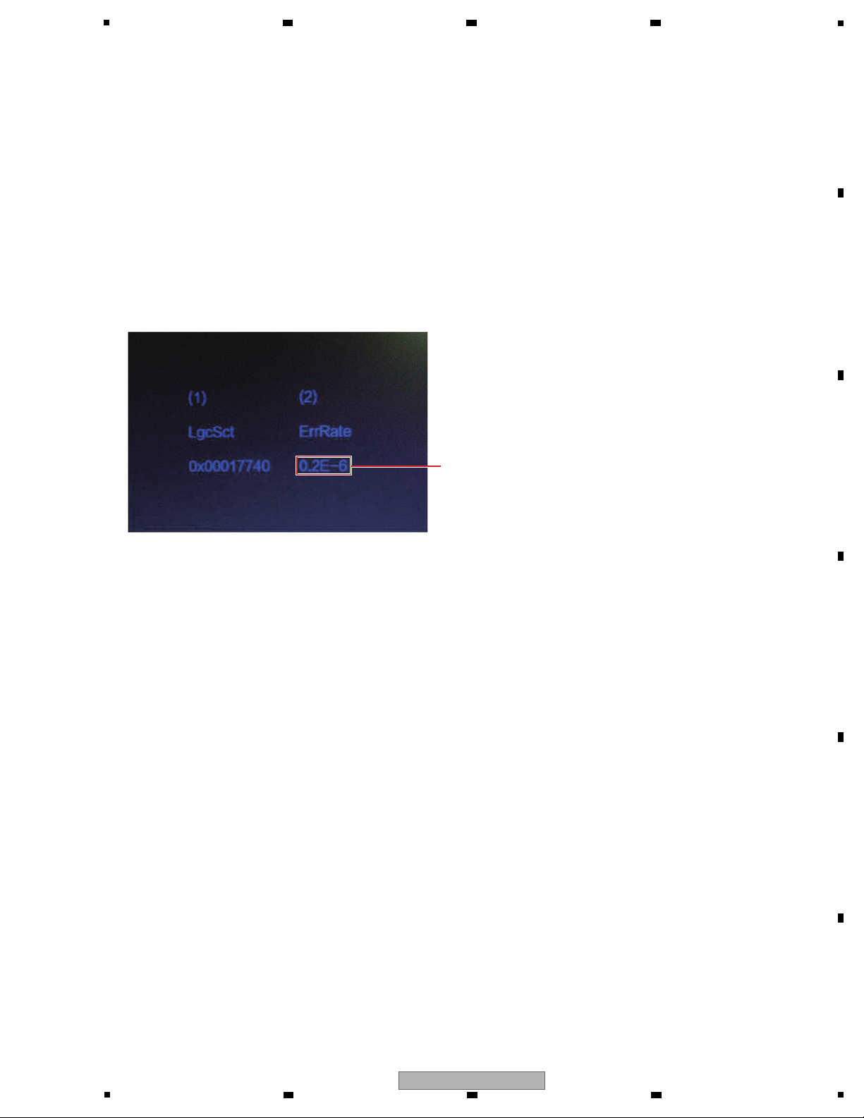
(1) Physical address of the disc
(2) Error rate of the disc
The indication "x.xE-X" denotes the error rate.
Example: 3.5E-5 = 3.5 x 10
-5
6 7 8
A
B
C
D
BDP-LX58-K
5
6 7 8
E
F
25
A
[ Effective indications ]
Failure in the playback system (block noise, interrupted sound, jumpiness of images, playback stopped in mid-course,
frozen image, etc.)
Failure judgment of the pickup, by comparing the error rates before and after cleaning of the lens
Notes:
1. Even if the values surpass 1.0 x 10
-3
immediately after measurement starts, if they fall to be around the reference level
several tens of seconds after, the pickup is probably OK.
2. Even with a normal pickup, the values may surpass 1.0 x 10
-3
during short-time measurement (around 30 seconds),
depending on the disc to be measured.
3. In rare cases, "0.0E-0" may be displayed for a moment. This is not a problem of the pickup.
4. If the measured error rates of a particular disc frequently surpass the reference value, that disc may have a problem.
Compare the error-rate values of such a disc with those of another disc without any scratches or dirt for judgment.
The examples of measured error rates when a test disc (GGV1368) is used are shown in the table below.
(As there are more than a few variations in values across discs or BD players used, the results measured using the
GGV1368 will not be completely the same. Use these values just for reference.)
For error-rate measurement of an entire DL disc (including that of the second layer), it is recommended to measure the
error rate using a PC.
When a PC is used for measurement, measured error-rate values will be graphed, which makes this method suitable for
error-rate measurement of an entire DL disc.
(For details on measurement, refer to the SKH14001 manual.)
[OK/NG judgment]
Disc Reference value
BD 1.0 x 10
-3
LgcSct Error rate
0x0001FC80
DVD
4.72E-4
0X00020DC 0.6E-6
0X00021F00 0.1E-6
0X000227A0 0.3E-6
0X000238E0 0.1E-6
0X00025B60 0.6E-6
0X00026400 0.2E-6
0X00027540 0.4E-6
0X00028F20 0.0E-0
0X0002A060 9.9E-5
0X0002B1A0 3.62E-4
0X0002C2E0 0.3E-6
0X0002D860 1.1E-5
0X0002E9A0 0.5E-6
0X0002FAE0 0.6E-6
0X00030380 0.0E-0
0X000314C0 0.1E-6
0X00032600 0.1E-6
LgcSct Error rate
0X00032EA0
0.1E-6
0X00033FE0 0.2E-6
0X00035120 0.3E-6
0X00036260 0.0E-0
0X00036B00 0.4E-6
0X00037C40 1.4E-5
0X00038D80 0.3E-6
0X00039EC0 5.7E-5
0X0003A760 0.1E-6
0X0003B000 0.7E-6
0X0003C560 0.4E-6
0X0003CE00 1.3E-5
0X0003DF40 0.0E-0
0X0003F080 0.2E-6
0X000401C0 0.3E-6
0X00040A60 0.6E-6
0X00041BA0 0.0E-0
0X00042CE0 0.4E-6
1.0 x 10
-3
CD Error rate measurement not available
1
2 3 4
B
C
D
E
F
26
1
2 3 4
BDP-LX58-K
5
[1] Top cover
(1) Remove the 5 screws.
(IBZ30P060FCC)
(2) Remove the 6 HEX screws.
(Black model: 63-N40060-BF3)
(Silver model: 63-N40060-BF2)
(3) Separate the lower parts of both sides of the
top cover from the back chassis by wedging
your finger tips between them then lift the top
cover while spreading the lower parts of the
top cover. Then detach the top cover by pulling
it backward.
Note:
As the top cover is securely pressed into the front
panel, detaching it will require a strong pull.
When reattaching the top cover, be careful not to let it bulge beyond the level of the front panel.
1
-1
Top cover
NG: Top cover bulging out
Front panel (front, lower)
Top cover
• Rear view
• Rear view
×5
2
×3
2
3
-2
3
-3
3
-1
3
×3
Note on reassembly of the top cover
Note:
(1) Do NOT look directly into the pickup lens. The laser beam may cause eye injury.
(2) Even if the unit shown in the photos and illustrations in this manual may differ from your product, the
procedures described here are common.
6 7 8
7. DISASSEMBLY
A
B
C
D
E
F
BDP-LX58-K
5
6 7 8
27
1
Clearance between the front panel
and the top cover: 0.2 mm or less
Guide of clearances and level differences during top cover reassembly
Clearance between the front panel
and the top cover: 0.2 mm or less
Downward level difference from the
Panel Base Assy to the bonnet: 0–0.5 mm
Downward level difference from the
Panel Base Assy to the bonnet: 0–0.5 mm
Front
Top cover
Top cover
Panel base Assy
• Side view
Panel base Assy
[2] Tray cap Section
(1) Press the u STANDBY/ON button to turn on
the power.
(2) Press the h button to open the tray.
(3) Remove the Tray cap section by removing
the 4 hooks.
(4) Press the h button to close the tray.
(5) Press the u STANDBY/ON button to turn off
the power.
1 5
3
3 3
3
3
224
4
Tray cap section
Screwdriver
(3 mm in dia. or less)
• Bottom view
• How to open the tray when the unit cannot be turned ON
Forced ejection hole
Bottom plate
Insert a screwdriver or tweezers of 3 mm or less
in dia. into the forced ejection hole on the bottom
plate then slide it in the direction of the arrow, as
indicated in the figure.
When the tray pops out a little, pull it manually.
Tray opens.
A
2 3 4
B
C
D
E
F
28
1
2 3 4
BDP-LX58-K

[3] BD LOADER
• D Main shield top
(1) Remove the 1 screw.
(IBZ30P060FCC)
(2) Remove the 3 screws.
(BBZ30P080FTB)
(3) Remove the 1 rivet.
• BD LOADER
(1) Disconnect the 2 flexible cables and 1
connector.
(CN3004, 3005, 3007)
(2) Remove the 4 screws.
(BBZ30P080FTB)
(3) Remove the 2 rivets.
(4) Remove the Mecha shield top.
Mecha shield top
4
(4) Remove the D Main shield top.
MAIN BOARD Assy
BD LOADER
2
2
2
2
33
Front side
1
1
1
CN3007
CN3005
CN3004
• Remove the Top cover.
(See "[1] Top cover".)
• Remove the Tray cap section.
(See "[2] Tray cap section".)
D Main shield top
4
1
2 2
2
3
• Rear view
Front side
Front side
5
6 7 8
A
B
C
D
E
F
BDP-LX58-K
5
6 7 8
29

1
Side cushion F
Side cushion F
Side cushion R
Side cushion R
5
5
(5) Remove the 2 Side cushion F and
2 Side cushion R.
• Dressing Cables of the BD LOADER Assy
Mecha sheild top
1
1 Dress the cables of the 4P connector Assy so that they are located as far as possible from the FFC.
2 Be careful that the 4P connector Assy and FFC are not pinched by the Mechanical Shield top.
2
Bend the cables around the edge of the FFC spacer.
Fit the cables into the gap between the BD LOADER
and the Mecha shield bottom.
After replacing the BD LOADER, fit the cables of the
4P connector Assy into the gap between the BD LOADER
and the Mecha shield bottom, as shown in the photo above,
then dress the cables so that they are bent around the
edge of the FFC spacer.
After the BD LOADER is detached for replacement,
reattach the BD LOADER so that the FFC spacer can
be seen.
FFC spacer
A
2 3 4
B
C
D
E
F
30
BDP-LX58-K
1
2 3 4

Lens Cleaning and Replacement of the Rubber Belt
(1) Remove the 4 screws.
Front side
11
1
1
(7) Remove the BD LOADER.
7
BD LOADER
Top cover
(6) Remove the 4 screws.
(BBZ30P080FTB)
6
6
6
6
BD LOADER
5
6 7 8
A
B
C
D
E
F
BDP-LX58-K
5
6 7 8
31

1
Pickup lens
Top cover Top cover
Front side
(4) Unhook the hooks on the rear of the BD
LOADER, using a screwdriver or similar tool.
(Unhooking is not possible when the entire
surface of the rear-rubber tape is glued.)
(5) Unhook the two hooks, one on each side of
the BD LOADER, in the same manner then
remove the top cover.
(6) Cleaning of the pickup lens becomes possible
in this state.
4 4
55
• Rear view
Front side
Clean the pickup lenses when it is stained, using
the following cleaning materials:
Cleaning liquid : GEM1004
Cleaning paper: GED-008
(2) Peel off only the upper parts of the two
side-rubber tapes, one on each side of the
BD LOADER. (Don't peel off the entire
surface of a side-rubber tape. Only peel off
the parts that are glued to the top cover of the
BD LOADER.)
(3) Peel off only the upper part of the rear-rubber
tape that is glued to the rear of the BD LOADER.
Front side
2 2
3
Side rubber Side rubber
Rear rubber
• Rear view
A
2 3 4
B
C
D
E
F
32
BDP-LX58-K
1
2 3 4

5
(3) Remove the 2 screws.
(64-T30040-103)
(4) Remove the 1 screw.
(BBZ30P080FTB)
• Rear view
343
• Cable dressing between the FRONT CONTROL BOARD Assy/SWITCH BOARD Assy and the RELAY BOARD Assy
RELAY BOARD
Assy
FRONT CONTROL BOARD Assy,
SWITCH BOARD Assy
• The cables must not touch metallic parts.
• Secure sufficient distances between the cables
and metallic parts.
[4] RELAY and MAIN BOARD Assemblies
(1) Remove the 2 rivets.
(2) Remove the RELAY BOARD Assy by
disconnect the 3 connectors, 1 BtoB connector.
(XP1 to 4)
RELAY BOARD Assy
XP1
XP2
XP3
XP4
×3
1 1
2
2
• Remove the Top cover.
(See "[1] Top cover".)
• Remove the D Main shield top.
(See "[3] BD LOADER".)
Rubber belt
7
(7) Remove the tray to change the rubber belt.
(As the tray has no holddown in this state, it
can be pulled upward. When returning the tray
back, place it without changing the Loader
position.)
6 7 8
A
B
C
D
BDP-LX58-K
5
6 7 8
E
F
33

1
• POWER BOARD Assy
(1) Disconnect the 2 bridge connectors and
1 connector.
(CN501, 5000, 5001)
(2) Remove the 1 screw.
(64-W30060-105)
(3) Remove the POWER BOARD Assy by removing
the 5 screws.
(IBZ30P060FCC)
POWER BOARD Assy
2
3
3 3
3
3
×2
1
1
CN1509
CN1505
CN501
[5] AUDIO and POWER BOARD Assemblies
• AUDIO BOARD Assy
(1) Remove the 1 screw.
(IBZ30P060FCC)
(2) Remove the 2 screws.
(BBZ30P080FTB)
(3) Disconnect the 2 bridge connectors.
(CN5000, 5001)
(4) Remove the 1 screw.
(64-W30060-105)
(5) Remove the AUDIO BOARD Assy by removing
the 4 screws.
(IBZ30P060FCC)
AUDIO BOARD Assy
• Rear view
1
2 2
×2
3
CN5000
CN5001
4
5
5
5
5
• Remove the Top cover.
(See "[1] Top cover".)
• Remove the D Main shield top.
(See "[3] BD LOADER".)
(5) Disconnect the 4 bridge connectors, 3 flexible
cables and 1 connector.
(CN1505, 1509, 3004, 3005, 3007, 3023,
5000, 5001)
(6) Remove the MAIN BOARD Assy by removing
the 5 screws.
(IBZ30P060FCC)
AUDIO BOARD AssyPOWER BOARD Assy
MAIN BOARD AssyRS BOARD Assy
×3
6 6
6
6
6
5
×2
5
×2
5
5
CN3007
CN5000
CN5001
CN3023
CN1509
CN1505
CN3005
CN3004
A
2 3 4
B
C
D
E
F
34
1
BDP-LX58-K
2 3 4

5
[6] Front panel Section
(2) Disconnect the 3 connectors.
(CN501, 5000, 5001)
(3) Remove the Front panel Section.
(1) Remove the 6 screws.
(Black model: BBZ30P080FTB)
(Silver model: BBZ30P080FNI)
• Bottom view
1
1
1 1 1
1
3
Front panel Section
RELAY BOARD Assy
XP2
XP3
XP4
×3
2
• Remove the Top cover.
(See "[1] Top cover".)
• Remove the Tray cap section.
(See "[2] Tray cap section".)
• Note on replacement of the AC inlet (on the Power Connection Assy)
Turn the AC inlet clockwise 360° to twist
the cables.
6 7 8
A
B
C
D
E
BDP-LX58-K
5
6 7 8
F
35

1
[How to read and write the barcode data to the unit]
In addition to the two conventional methods of reading/writing barcode data, a new method using a USB memory device has been added.
It is recommended to use the new method if you have a USB memory device, because with this method setting is easier and input errors
will be less likely to be generated.
For details on the conventional methods (with the aid of the remote control unit or a combination of a PC and a special tool for servicing),
refer to the Service Manual of the BDP-160.
Please perform either method when replacing MAIN BOARD Assy or BD LOADER.
USB memory device (one that can be
recognized in Normal Operation mode)
3 It is easy to read and write the barcode data. It is necessary to prepare a USB memory device.
Note:
• Change the Destination setting after MAIN BOARD Assy is replaced. After that, update the latest firmware.
• Please confirm that the USB memory device is recognized after inserting the USB memory device to the USB port.
(Due to protect wrong connection)
Note: Be sure to update the firmware before starting adjustments or settings.
——————————
This time Adjustment Points
Adjustment Points
[1] When replace the BD LOADER
Mechanical
point
Write barcode data for pickup adjustment
Electric
point
When replace
the BD LOADER
——————————
This time
[2] When replace the MAIN BOARD Assy
Mechanical
point
• Read out barcode data for pickup adjustment
(Before replacing MAIN BOARD Assy)
• Write barcode data for pickup adjustment
(After replacing MAIN BOARD Assy)
Electric
point
When replace
the MAIN BOARD Assy
[About barcode data for pickup adjustment]
A new BD LOADER is installed in this model and it has 64 bit barcode data for pickup adjustment.
Therefore when replacing a new BD LOADER, it is necessary to write barcode data of the new BD LOADER.
The barcode data is stored in a MAIN BOARD Assy. Therefore when replacing the MAIN BOARD Assy, it is necessary to
read out the original barcode data before replacing it and write the data to a new MAIN BOARD Assy after installing it.
Necessary tools Good Point Bad Point
Remote control unit1 It is not necessary to prepare other tools such as
Service jig and PC.
Need to enter 64 letters barcode data by using
a Remote control unit.
Service jig (GGF1676), PC,
Driver and Read/Write program
2 It is very easy to read and write the barcode data. It is necessary to prepare other tools such as
Service jig and PC.
(But Service Jig is very cheap.)
[Attention point when replacing MAIN BOARD Assy]
When the unit is no power condition due to defective of a MAIN BOARD Assy, original barcode data is not able to read
out from it. In such a case, read out the data of the barcode label attached to the BD LOADER, referring to the SKH15002
Service Knowhow manual.
2 3 4
8. EACH SETTING AND ADJUSTMENT
8.1 NECESSARY ITEMS FOR ADJUSTMENTS
A
B
C
D
E
F
36
BDP-LX58-K
1
2 3 4

5
The procedure for firmware updating is described below.
1. Before performing updating, check the version of the current firmware installed in the unit.
To display the current firmware version, press the [HOME MENU] button to enter the menu, select "Home Menu,"
"Initial Setup," "Options," "System Information," then "Next Screen," using the i/j/k/l buttons, then press the [ENTER]
button.
The firmware version for the AVX controller will be displayed at the same time for the BDP-LX58/BDP-LX88.
2. Download the DLdiscidentifier.txt, DVD.bin, AVX15I_xxxx.FW, and BDP-LX88_Vxx.xx.bin updater files from the Web site to
store them in the root directory of the USB memory device plugged into the PC.
Note: The same updater files are used for the BDP-LX58 and BDP-LX88.
3. After storage is completed, unplug the USB memory device from the PC then plug it into the unit. While a message that
a USB memory device is connected is displayed on the screen, press the [HOME MENU] button to enter the menu, then
select "Home Menu," "Initial Setup," "Options," "Update," then "USB Storage."
After you press the [ENTER] button, the system will search for the updater files. After the updater files are found, press the
[ENTER] button again to start updating.
Note: As the updating process of the AVX Controller is skipped when no updating is required for it, the time required for
updating varies greatly, as follows:
Time required for normal updating: 13 to 20 min.
Time required without updating of the AVX Controller: 30 sec. to 1 min.
4. After updating is completed, the unit will automatically restart.
Be sure to confirm the firmware version after restart. Updating is completed when the firmware version has been updated to
the appropriate one.
If the firmware version is not updated to the appropriate one, check the updater files then perform the updating procedure again.
Not to be used
DSP version
Note: As no DSP is mounted in the BDP-LX58, "###" will be displayed in this place.
Event Controller version
AVX Controller version
1. Plug a USB memory device into this unit in Normal mode.
(Make sure that the USB memory device is recognized.)
2. Enter Service mode.
(See "HOW TO ENTER SERVICE MODE .")
3. Select "[6] Repair Service" then press the [ENTER] button.
4. Select "Readout 480 2D barcode to USB memory"
then press the [ENTER] button.
5. The message "OK" will be displayed on the screen when
copying of the barcode data to the USB memory device
is finished.
At that moment, a "2D_barcode_data.txt" file, in which
64-bit barcode data have been written, is stored in the
USB memory device.
6. Quit Service mode by pressing the [STOP] button.
6 7 8
8.2 UPDATING OF THE FIRMWARE
A
B
8.3 HOW TO READ OUT BARCODE DATA USING A USB MEMORY DEVICE
C
D
E
5
6 7 8
BDP-LX58-K
F
37

1
• If the BD LOADER is replaced, follow the procedure from
Step 1 below.
• If the MAIN BOARD Assy is replaced, follow the procedure
from Step 5 below.
1. Open Notepad from Accessories on your PC.
Plug the USB memory device into the PC.
2. Type the 64-digit barcode that is attached to the back of
the BD LOADER for service into a Notepad file.
(Be careful of input errors, because the barcode data are
adjustment data for the new part.)
3. Store the Notepad file as "2D_barcode_data.txt " in the
root directory of the USB memory device.
After storage, remove the USB memory device from the
PC.
4. Plug the USB memory device in which the
"2D_barcode_data.txt" file is stored into the BDP unit
whose BD LOADER has been replaced.
(Make sure that the USB memory device is recognized.)
5. Enter Service mode.
(See "HOW TO ENTER SERVICE MODE.")
6. Select "[6] Repair Service" then press the [ENTER] button.
7. Select "Write 2D barcode from USB memory" then press
the [ENTER] button.
8. The message "OK" will be displayed on the screen when
copying of the barcode data from the USB memory device
is finished.
9. Quit Service mode by pressing the [STOP] button.
Note:
To prevent a future possible writing error, delete the
"2D_barcode_data.txt" file from the USB memory device on
the PC.
• If the MAIN BOARD Assy is replaced, the procedure is
completed at Step 9.
• If the BD LO
ADER is replaced, continue the remaining
Steps below.
10. Enter Service mode again.
11. Select "[6] Repair Service" then press the [ENTER]
button.
12. Select "Show 480 2D barcode" then press the
[ENTER] button.
13. Check that the 64-digit barcode being displayed is the
same as that attached to the BD LOADER.
If the barcode is not the same, perform the procedure
from Step 1 again.
2 3 4
8.4 HOW TO WRITE BARCODE DATA USING A USB MEMORY DEVICE
A
B
C
D
E
F
38
1
2 3 4
BDP-LX58-K

5
6 7 8
A
B
C
D
E
F
BDP-LX58-K
5
6 7 8
39

1
NOTES: - Parts marked by “NSP” are generally unavailable because they are not in our Master Spare Parts List.
-
The > mark found on some component parts indicates the importance of the safety factor of the part.
Therefore, when replacing, be sure to use parts of identical designation.
-
Screws adjacent to b mark on product are used for disassembly.
-
For the applying amount of lubricants or glue, follow the instructions in this manual.
(In the case of no amount instructions, apply as you think it appropriate.)
AAA 700 size manganese batteries
YXE8, AXQ5
only
or or
FXE
only
2 3 4
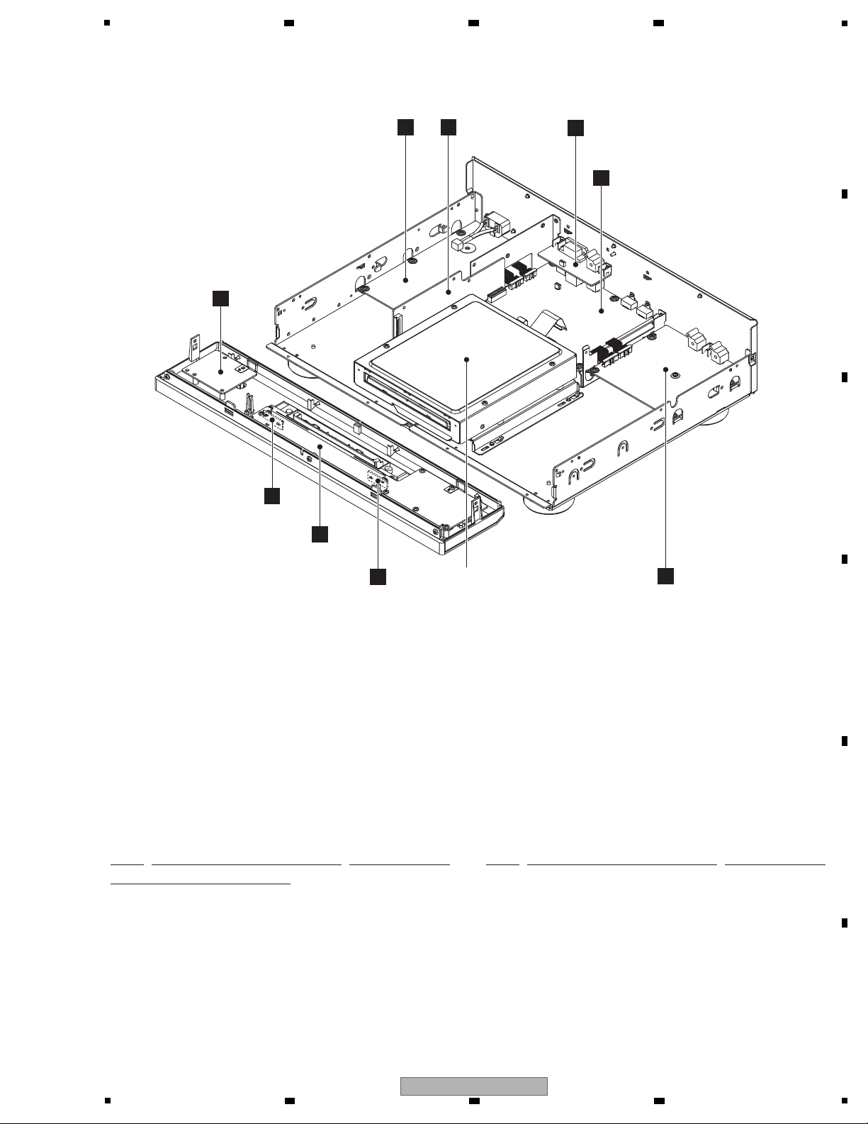
9. EXPLODED VIEWS AND PARTS LIST
A
9.1 PACKING SECTION
B
C
D
E
F
40
1
2 3 4
BDP-LX58-K

5
6 7 8
(1) PACKING SECTION PARTS LIST
Mark No. Description Part No.
1 1..Remote Control See Contrast table (2)
2 2..Battery Cover AZN8047
> 3 Power Cord See Contrast table (2)
4 Software License Notice See Contrast table (2)
5 Operating Instructions See Contrast table (2)
6 Operating Instructions See Contrast table (2)
7 Operating Instructions See Contrast table (2)
8 Operating Instructions See Contrast table (2)
9 Software Update Notice See Contrast table (2)
10 One Blue Label 71-BLURAY-EXTB1
A
NSP 11 Warranty Card See Contrast table (2)
12 Poly Bag See Contrast table (2)
13 Pad R 75-LX58R1-EA0
14 Pad L 75-LX58L1-EA0
15 Packing Sheet 74-150085-50GB1
16 Packing Case See Contrast table (2)
NSP 17 Corrugated Board 76-184810-0AP
18 Taiwan Label See Contrast table (2)
(2) CONTRAST TABLE
BDP-LX58-K/YXE8, BDP-LX58-S/YXE8, BDP-LX58/LXE, FXE and AXQ5 are constructed the same except for the following:
Mark No. Symbol and Description
1 Remote Control VXX3392 VXX3392 VXX3392 VXX3392 VXX3393
> 3 Power Cord ADG7123 ADG7123 ADG7123 ADG7120 ADG7122
4 Software License Notice 70-PONEER-LCSB4 70-PONEER-LCSB4 70-PONEER-LCSB4 70-PONEER-LCSB4 70-PONEER-LCSB5
5 Operating Instructions (En) 72-BDPL88-GBRB1 72-BDPL88-GBRB1 72-BDPL88-GBRB1 Not used Not used
6
Operating Instructions
(Fr, De, It, Nl, Es)
7 Operating Instructions (Zhtw) Not used Not used 72-BDPL58-TWNB1 72-BDPL58-TWNB1 Not used
8 Operating Instructions (Zhcn) Not used Not used Not used Not used 72-BDPL58-CHNB1
9 Software Update Notice 70-BDPX58-SHTB2 70-BDPX58-SHTB2 70-BDPX58-SHTB2 70-BDPX58-SHTB2 70-BDPX58-SHTB1
NSP 11 Warranty Card 70-PIONBD-WARD4 70-PIONBD-WARD4 Not used Not used 70-BDPL58-WARB2
12 Poly Bag 74-024035-50CD2 74-024035-50CD2 74-024035-50CD2 74-024035-50CD2 74-024035-50CD3
BDP-LX58-K
/YXE8
72-BDPL88-EURB1 72-BDPL88-EURB1 Not used Not used Not used
BDP-LX58-S
/YXE8
BDP-LX58
/LXE
BDP-LX58
/FXE
BDP-LX58
/AXQ5
B
C
D
18 Taiwan Label Not used Not used Not used 71-BDPL88-FXEB1 Not used
BDP-LX58-K
5
6 7 8
E
F
41

1
D
F
E
a
c
b
C
D
F
E
A
C
B
c
Cable tie
Refer to
“9.3 BD LOADER SECTION”.
9.2 EXTERIOR SECTION
A
B
2 3 4
C
D
E
F
42
1
BDP-LX58-K
2 3 4

5
D
F
C
G
G
H
I
I
H
B
A
E
a
b
K
K
J
J
L
L
CONTACT SIDE
NON-CONTACT
SIDE
A
B
G
H
I
A
C
B
.
6 7 8
A
B
C
D
E
F
BDP-LX58-K
5
6 7 8
43

1
2 3 4
(1) EXTERIOR SECTION PARTS LIST
Mark No. Description Part No.
1 MAIN BOARD Assy See Contrast table (2)
A
2 AUDIO BOARD Assy 08-BDLX58-AD1
FRONT CONTROL BOARD Assy
3
08-BDLX58-FV0
4SWITCH BOARD Assy 08-BDLX58-SW0
5 LED BOARD Assy 08-BDLX58-LE0
No. Description Part No.
Mark
26 ACC Screw 63-S26070-AB2
27 ACC Spring 67-LX88A1-0E2
28 AL Front Panel See Contrast table (2)
29 Pioneer Badge 67-104290-0A0B1
30 Ring See Contrast table (2)
6 LED BOARD Assy 08-BDLX58-LE1
7 RS BOARD Assy 08-BDLX58-RS0
8 RELAY BOARD Assy 08-BDLX58-RL0
9POWER BOARD Assy 08-BDLX58-PW0
> 10 Power Connection Assy 08-BDLX58-AC0
B
NSP 11 Bottom Plate 67-LX58W1-0E0B1
NSP 12 Main Chassis 67-LX58R1-0E0
NSP 13 D Main Shield Top 67-LX88V3-0E0
NSP 14 D Main Shield Bottom 67-LX88H5-0E0
15 Back Chassis See Contrast table (2)
NSP 16 Top Cover See Contrast table (2)
17 Mold Foot Assy 08-LX58E1-000
18 Rivet 57-168570-12G
19 Cushion 60*16 (Bonnet) 54-184490-000
C
20 CR Sheet (Bonnet) 59-184760-000
21 Cupper Sheet 58-188930-000
22 Window 57-LX58L1-0HHB1
23 Tray Cap See Contrast table (2)
24 Cushion 92*10 (ACC Mold) 54-184670-000
25 ACC Mold 55-LX88D2-0HAB1
31 Panel Base Assy See Contrast table (2)
32 Lens 55-LX88L1-0HM
33 Lens Holder 55-LX88W1-0HA
34 Power Button Assy See Contrast table (2)
35 Play Button See Contrast table (2)
NSP 36 Earth Plate 67-LX88Q1-0B0
37 Tape Cupper Sheet 54-151900-000
38 • • • • •
39 Screw IBZ30P060FCC
40 Screw BBZ30P100FTB
41 Screw 64-B40100-103
42 Screw BBZ30P080FTB
43 Screw See Contrast table (2)
44 Screw See Contrast table (2)
45 Screw 64-T30040-103
46 Screw CBZ30P080FTB
47 Screw 64-W30060-105
D
(2) CONTRAST TABLE
BDP-LX58-K/YXE8, BDP-LX58-S/YXE8, BDP-LX58/LXE, FXE and AXQ5 are constructed the same except for the following:
Mark No. Symbol and Description
1 MAIN BOARD Assy 08-BDLX58-MA1/Y 08-BDLX58-MA1/Y 08-BDLX58-MA2 08-BDLX58-MA2/F 08-BDLX58-MA4
15 Back Chassis 67-LX58B1-0E0B3 67-LX58B1-0E0B4 67-LX58B1-0E0B2 67-LX58B1-0E0B5 67-LX58B1-0E0B7
NSP 16 Top Cover 67-LX58T1-0E0B1 67-LX58T1-0E0B2 67-LX58T1-0E0B1 67-LX58T1-0E0B1 67-LX58T1-0E0B1
23 Tray Cap 55-LX88D1-0HMB4 55-LX88D1-0HMB5 55-LX88D1-0HMB4 55-LX88D1-0HMB4 55-LX88D1-0HMB4
28 AL Front Panel 67-LX58F1-0A3B2 67-LX58F1-0A3B3 67-LX58F1-0A3B2 67-LX58F1-0A3B2 67-LX58F1-0A3B2
30 Ring 56-BD44W2-0HAB1 56-BD44W2-0HAB2 56-BD44W2-0HAB1 56-BD44W2-0HAB1 56-BD44W2-0HAB1
E
F
31 Panel Base Assy 08-LX58F2-000 08-LX58F2-001 08-LX58F2-000 08-LX58F2-000 08-LX58F2-000
34 Power Button Assy 02-BD44K1-00XB1 02-BD44K1-00XB2 02-BD44K1-00XB1 02-BD44K1-00XB1 02-BD44K1-00XB1
35 Play Button 56-BD44K4-0HAB1 56-BD44K4-0HAB2 56-BD44K4-0HAB1 56-BD44K4-0HAB1 56-BD44K4-0HAB1
43 Screw BBZ30P080FTB BBZ30P080FNI BBZ30P080FTB BBZ30P080FTB BBZ30P080FTB
44 Screw 63-N40060-BF3 63-N40060-BF2 63-N40060-BF3 63-N40060-BF3 63-N40060-BF3
BDP-LX58-K
/YXE8
BDP-LX58-S
/YXE8
BDP-LX58
/LXE
BDP-LX58
/FXE
BDP-LX58
/AXQ5
44
BDP-LX58-K
1
2 3 4

5
BD LOADER SECTION PARTS LIST
Mark No. Description Part No.
1 1..BD LOADER 08-BDLX58-SH0
2 2..Rubber Belt 59-190010-000
NSP 3 2..Top Rubber 59-184850-000
NSP 4 2..Side Rubber 59-117420-000
NSP 5 2..Bottom Rubber B 59-182190-000
NSP 6 2..Bottom Rubber S 59-117470-000
NSP 7 2..Cushion 35*35 54-187860-000
NSP 8 Mecha Shield Top 67-LX88V4-0E0
9 Top Cushion 54-182230-000
10 Side Cushion R 54-182180-000
11 Side Cushion F 54-182170-000
12 Front Cover 58-182150-0HH
NSP 13 Mecha Shield Bottom 67-LX88H7-0E0B1
14 Float Rubber 59-976590-003
NSP 15 Rear Rubber 59-184880-000
16 Rear Cushion T 54-182240-000
17 Rear Cushion BR 54-184900-000
18 Rear Cushion BL
54-184910-000
19 FFC Cover 58-184930-0HH
20 FFC Sheet 54-184890-000
21 Wire Sheet 54-188070-000
NSP 22 Mecha Frame 67-LX58H1-0E0
23 PC Spacer 58-184970-0HH
24 Laser Caution Label 71-BD1100-LASB2
25 • • • • •
26 • • • • •
27 • • • • •
28 Rivet 57-184680-02G
29 • • • • •
30 Screw BBZ30P080FTB
31 FLOAT Screw 64-W30060-303
32 Screw 64-W30060-105
9.3 BD LOADER SECTION
6 7 8
A
B
C
D
E
F
BDP-LX58-K
5
6 7 8
45

1
EMAD3
EMAD2
EMAD1
EMAD5
EMAD6
EMAD7
EMDQ5
EMDQ15
EMDQ14
EMDQ12
EMDQ13
EMDQ14
EMDQ13
EMDQ12
EMDQ11
EMDQ10
EMDQ9
EMDQ8
EMDQ0
EMDQ1
EMDQ2
EMDQ3
EMDQ4
EMDQ5
EMDQ6
EMDQ7
EMDQ0
EMDQ1
EMDQ2
EMDQ3
EMDQ4
EMDQ7
EMDQ6
EMDQ10
EMDQ11
EMAD6
EMAD5
EMAD4
EMAD8
EMAD7
EMDQ15
XCSGA
EVSCK
EVREQI
EVREQO
EM232TX
EM232RX
HDSCL
EMDQ8
EMDQ9
EMAD1
EMAD2
EMAD3
EVSO
EVSI
XDSP1CS
DSPSI
DSPSCK
EXSO
EXSCK
XGARST
XEMRST
XINTGA
AUDIOSCL
AUDIOSDA
XDSP1IRQXHDOSDIRQ
DSPSO
EX2OE
EMDQ15
EX2ST
EMBA1
EMBA0
XEMSDCS
XEMRAS
XEMCAS
EMAD10
EMCKE
EMSDCLK
EMDQM1
EMDQM0
EMAD9
EMAD10
EMAD11
EMBA0
EMBA1
EMSDCLK
XEMSDCS
EMCKE
232XEMEV
EMAD4
EMAD9EMAD11
EMAD12
EMAD12
EMAD8
DIRPOW
HDSDA
XEMWE
VPPOW
VCH1234-A
C116
VCH1234-A
C104
VCH1234-A
C107
C217
NM
C175
C179
CCG1318-A
C207
CCG1318-A
C210
C127
C154
22p/50
C122
CCG1311-A
C178
NM
C208
NM
C138
0.01u/25
C193
10p/50
C216CCG1311-A
C218
NM
C194
22p/50
C158
CCG1318-A
C121
NM
C124
CCG1318-A
C147
CCG1318-A
C125
CCG1311-A
C205
CCG1318-A
C206
470p/50
C201
470p/50
C123
NM
C203
CCG1318-A
C119
C106
NM
C146
NM
C209
C186
7p/50
C109
NM
C187
7p/50
C211
C223
CCG1318-A
C120
C204
NM
C105
NM
C212
100p/50
C214
NM
C173
NM
C118
NM
C156
470p/50
C222
10p/50
C129
C180
7p/50
C144
10p/50
C126
C155
C152
CCG1311-A
C192
33p/50
C200
CCG1318-A
C221
NM
C142
NM
C219
NM
C140
CCG1311-A
C108
NM
C176
C157
C215 NM
C171
CCG1311-A
C148
470p/50
C153
100p/50
C117
330p/50
C220
CCG1311-A
C202
NM
C199
100p/50
C213
NM
C170
NM
GNDD
GNDD
GNDD
IC102
M12L128168A-5TG2N
VDD1
1
DQ0
2
VDDQ1
3
DQ1
4
5
DQ2
6
VSSQ1
7
DQ3
8
DQ4
9
VDDQ2
10
DQ5
11
DQ6
12
VSSQ2
13
DQ7
14
VDD2
15
LDQM
16
WE
17
CAS
18
RAS
19
CS
20
BA0
21
BA1
22
A10_AP
23
A0
24
A1
25
A2
26
A3
27
VDD328VSS1
29
A4
30
A5
31
A6
32
A7
33
A8
34
A9
35
A11
36
NC1
37
CKE
38
CLK
39
UDQM
40
NC2
41
VSS2
42
DQ8
43
VDDQ3
44
DQ9
45
DQ10
46
VSSQ3
47
DQ11
48
DQ12
49
VDDQ4
50
DQ13
51
DQ14
52
VSSQ4
53
DQ15
54
VSS3
R5S726B0D216FP
IC101
PD14/D14/SD_D3
1
PD15/D15/SD_D2
2
PVCC1
3
PB1/A1/SSISCK3
4
VSS1
5
PB2/A2/SSIWS3
6
PB3/A3/SSIDATA3
7
PB4/A4/CTS0
8
PJ6/SD_D3/CS4/RXD1/AUDATA2
9
PJ7/SD_D2/BS/TXD1/AUDATA3
10
PVCC2
11
PB5/A5/RTS0
12
VSS2
13
PB6/A6/SCK0/SSISCK2
14
VCC1
15
PB7/A7/RXD0
16
PB8/A8/TXD0
17
PB9/A9/SCK1/SSIWS2
18
PJ8/TIOC3A/A23/SCK2/SSISCK2/TEND0
19
PJ9/TIOC3B/A24/RXD2/SSIWS2/DREQ0
20
PJ10/TIOC3C/A25/TXD2/SSIDATA2/DACK0
21
PVCC3
22
PB10/A10/RXD1
23
VSS3
24
PB11/A11/TXD1
25
VCC2
26
PB12/A12/SCK2/SSIDATA2
27
PB13/A13/RXD2
28
PB14/A14/TXD2
29
PB15/A15/RSPCK0/TIOC0B
30
PB16/A16/SSL00/TIOC1B
31
PB17/A17/MOSI0/TIOC2B
32
PB18/A18/MISO0/TIOC3B
33
PVCC4
34
PB19/A19/SSISCK0/TIOC0C
35
VSS4
36
PB20/A20/SSIWS0/TIOC0D
37
PB21/A21/SSIRXD0/TIOC3C
38
PB22/A22/SSITXD0/TIOC3D
39
PK0/SCK3/RTC_X140PK1/TXD3/RTC_X2
41
PF6/IRQ2/RXD342PF7/IRQ3/RXD443PVCC544CKIO45VSS546RES
47
VSS648PLLVCC
49
NMI50VCC351EXTAL52XTAL53VSS7
54
PG2/DM1/PINT255PG3/DP1/PINT356VSS8
57
PVCC6
58
PG0/DM0/PINT059PG1/DP0/PINT160ASEMD61PH0/AN0/IRQ0/VBUS62PH1/AN1/IRQ1/RXD063PH2/AN2/IRQ2/WAIT
64
PH3/AN3/IRQ365PH4/AN4/PINT4/RXD1
66
PH5/AN5/PINT5/RXD2
67
AVSS68PH6/AN6/PINT6/RXD3
69
AVCC70PH7/AN7/PINT7/RXD4
71
AVREF
72
TRST
73
ASEBRKAK/ASEBRK
74
TDO
75
TDI
76
TMS
77
TCK
78
AUDIO_X2
79
AUDIO_X1
80
PVCC7
81
PF0/RSPCK0/SPBCLK
82
VSS9
83
PF1/SSL00/SPBSSL
84
PF2/MOSI0/SPBMO_0/SPBIO0_0
85
PF3/MISO0/SPBMI_0/SPBIO1_0
86
PJ11/TIOC3D/IRQ0/SCK4/CRX0/IERXD/RSPCK2
87
PJ12/SSISCK3/A0/TXD4/CTX0/IETXD/SSL20
88
PVCC8
89
PF4/SPBIO2_0
90
VSS10
91
PF5/SPBIO3_0
92
VCC4
93
PA0/MD_CLK
94
PA1/MD_BOOT
95
PJ13/SSIWS3/IRQ1/RXD4/CRX1/CRX0/CRX1/MOSI2
96
PJ14/SSIDATA3/WDTOVF/CTX1/CTX0&CTX1/MISO2
97
PJ0/SD_CD/IRQ4
98
PC0/CS0/TIOC4A/AUDIO_XOUT
99
PVCC9
100
PC1/RD/TIOC4B/SPDIF_IN
101
VSS11
102
PC2/RD/WR/TIOC4C/SPDIF_OUT
103
VCC5
104
PC3/WE0/DQML/TIOC4D
105
PC4/WE1/DQMU/WDTOVF
106
PC5/RAS/IRQ4/CRX0/IERXD
107
PC6/CAS/IRQ5/CTX0/IETXD
108
PE0/SCL0/IRQ0
109
PE1/SDA0/IRQ1
110
PE2/SCL1/AUDIO_CLK
111
PE3/SDA1/ADTRG
112
PE4/SCL2/TCLKA
113
PE5/SDA2/TCLKB
114
PE6/SCL3/TCLKC
115
PE7/SDA3/TCLKD
116
PC7/CKE/IRQ6/CRX1/CRX0/CRX1
117
VSS12
118
PVCC10
119
PC8/CS3/IRQ7/CTX1/CTX0&CTX1
120
PD0/D0/SSISCK1/SIOFSCK/SPBMO_1/SPBIO0_1
121
PD1/D1/SSIWS1/SIOFSYNC/SPBMI_1/SPBIO1_1
122
PD2/D2/SSIRXD1/SIOFRXD/SPBIO2_1
123
PJ1/SD_WP/CS2/IRQ5/AUDIO_XOUT
124
PJ2/SD_D1/IRQ6/AUDCK
125
PVCC11
126
PD3/D3/SSITXD1/SIOFTXD/SPBIO3_1
127
VSS13
128
PD4/D4/RSPCK1/SCK3/CTS1
129
VCC6
130
PD5/D5/SSL10/TXD3/RTS1
131
PD6/D6/MOSI1/SCK4/CTS2
132
PJ3/SD_D0/IRQ7/AUDSYNC
133
PJ4/SD_CLK/CS1/AUDATA0
134
PJ5/SD_CMD/SCK1/AUDATA1
135
PVCC12
136
PD7/D7/MISO1/TXD4/RTS2
137
VSS14
138
PD8/D8/SD_CD/TIOC0A
139
PD9/D9/SD_WP/TIOC1A
140
PD10/D10/SD_D1/TIOC2A
141
PD11/D11/SD_D0/TIOC3A
142
PD12/D12/SD_CLK/IRQ2
143
PD13/D13/SD_CMD/IRQ3
144
L102
VTL1129-A
L106
L103
VTL1129-A
R101
47
2
1
4
3
6
5
8
7
R102
100
2
1
4
3
6
5
8
7
R103
100
2
1
4
3
6
5
8
7
R108
150
2
1
4
3
6
5
8
7
R124
22k
214
3
658
7
R120
47
2
1
4
3
658
7
R104
100
2
1
4
3
6
5
8
7
R109
150
2
1
4
3
6
5
8
7
R110
150
2
1
4
3
6
5
8
7
R119
47
2
1
4
3
658
7
22k
R117
22
214
3
658
7
R118
22
2
1
4
3
658
7
R141
100k
R107
47k
R237
47k
R136
10k
R137
10
R231
10
R142
100k
R143
10k
R147
10k
R150
10k
R105
2.2
R106
47
R232
10
R151
100k
R152
47k
R111
150
R112
150
R216NMR210
NM
R126
47k
R164
10
R169
22
R204
22
R225
10
R226
10
R206
47k
R227
10
R228
10
R158
47k
R160
47k
R162
47k
R23510R239
10
R240
10
R241
47
R245
47
R127
47k
R140NMR128
NM
R131
NM
R144
22k
R146
22k
R167
22k
R149
NM
R125
10
R168
47k
R262
47k
R222
3.3k
R161
47k
R122
150
R223
1M
R123
150
R156
47k
R153
47k
R214
NM
R165
NM
R166
NM
R212
NM
R213
NM
R145
NM
R270NMR271
NM
R254NMR269
NM
R276
47k
R247
NM
R179
47k
R171
NM
V+3R3_PVCC
V+3R3_PVCC
V+3R3_PVCC
V+1R25_VCC
V+1R25_EM V+1R25_PLL
V+1R25_EM
X101
ASS7120-A
12MHz
X1
1
NC1
2
NC2
4
X2
3
V+3R3_HHH
NM
NM
CCG1311-A
100p/50
NM
NM
CCG1318-A
470p/50
330p/50
CCG1318-A
47p/50
10p/50
VTL1129-A
256Mbit
A
1/10
2 3 4
10. SCHEMATIC DIAGRAM
10.1 MAIN BOARD ASSY (1/10)
A
B
C
D
E
F
46
BDP-LX58-K
1
2 3 4

EVREQO
EVREQI
JTDI
JTMRST
EM232TX
EM232RX
JTDI
JTDO
JTMS
JTCL
JTMRST
HDSCL
EVSI
HDSCL
HDSDA
EVSO
EVSCK
AUDIOSCL
AUDIOSDA
SPBIO3_0
SPBIO2_0
SPBIO1_0
SPBIO0_0
SPBSSL
SPBCLK
ASEBRKAK/ASEBRK
SPBIO1_0
SPBCLK
ASEMD
EX2OE
EMDQ11
EMDQ10
EMDQ6
EMDQ7
EMDQ4
EMDQ9
EMDQ3
EMDQ8
EMDQ2
EMDQ1
EMDQ0
EMDQ13
EMDQ12
EMDQ14
EMDQ5
EMDQ15
EX2ST
XEMCAS
XEMRAS
JTRST
JTDO
JTMS
JTCL
ASEMD
ASEBRKAK/ASEBRK
SPBIO0_0
SPBIO3_0
SPBSSL
SPBIO2_0
XRDGA
RYAF
HDSDA
MPEGSO
MPEGSCK
XEMWE
EMDQM1
EMDQM0
EMDQM0
MPEGREQI
MPEGSI
XMPEGCS
VPPOW
0.5F-14P
CN101
1
2
3
4
5
6
7
8
9
10
11
12
13
14
C115
NM
C161
NM
C196
12p/50
C158
CCG1318-A
C130
C166
CCG1311-A
C135
330p/50
C162
100p/50
C159
C113
NM
C114
NM
C157
C171
CCG1311-A
C163
CCG1318-A
C165
15p/50
C167
NM
C136
CCG1311-A
C160
C133
CCG1318-A
C132
330p/50
C170
NM
GNDD
GNDD
GNDD
GNDD
GNDD
MX25L6435EM2I-10G
IC103
CS#
1
SO/SIO1
2
WP#
3
GND
45
SI/SIO0
6
SCLK
7
HOLD#
8
VCC
PH3/AN3/IRQ365PH4/AN4/PINT4/RXD1
66
PH5/AN5/PINT5/RXD2
67
AVSS68PH6/AN6/PINT6/RXD3
69
AVCC70PH7/AN7/PINT7/RXD4
71
AVREF
72
TRST
73
ASEBRKAK/ASEBRK
74
TDO
75
TDI
76
TMS
77
TCK
78
AUDIO_X2
79
AUDIO_X1
80
PVCC7
81
PF0/RSPCK0/SPBCLK
82
VSS9
83
PF1/SSL00/SPBSSL
84
85
PF3/MISO0/SPBMI_0/SPBIO1_0
86
87
88
PVCC8
89
PF4/SPBIO2_0
90
VSS10
91
PF5/SPBIO3_0
92
VCC4
93
PA0/MD_CLK
94
PA1/MD_BOOT
95
RXD4/CRX1/CRX0/CRX1/MOSI2
96
TOVF/CTX1/CTX0&CTX1/MISO2
97
PJ0/SD_CD/IRQ4
98
PC0/CS0/TIOC4A/AUDIO_XOUT
99
PVCC9
100
PC1/RD/TIOC4B/SPDIF_IN
101
VSS11
102
103
VCC5
104
PC3/WE0/DQML/TIOC4D
105
PC4/WE1/DQMU/WDTOVF
106
PC5/RAS/IRQ4/CRX0/IERXD
107
PC6/CAS/IRQ5/CTX0/IETXD
108
PE0/SCL0/IRQ0
109
PE1/SDA0/IRQ1
110
PE2/SCL1/AUDIO_CLK
111
PE3/SDA1/ADTRG
112
PE4/SCL2/TCLKA
113
PE5/SDA2/TCLKB
114
PE6/SCL3/TCLKC
115
PE7/SDA3/TCLKD
116
L105
VTL1129-A
R135
22k
214
3
658
7
R134
22k
214
3
658
7
R189
22k
214
3
6
5
8
7
R132
22k
214
3
658
7
R133
22k
214
3
658
7
R208
NM
R255
100
R260
10
R141
100k
R107
47k
R138
NM
R224
NM
R139
NM
R211
51
R259
10
R258
10
R257
10
R209
51
R142
100k
R148
4.7k
R151
100k
R152
47k
R113
150
R217
10
R129
0
R216NMR210
NM
47k
R207
100
R205
51
R203
51
R227
10
R228
10
R154
47k
R155
10k
R157
10k
R158
47k
R162
47k
R184
10k
R183
10k
R182
10k
R181
2.2k
R180
2.2k
R177
22
R178
22
R238
10
R176
22
R172
22
R173
22
R175
22
R114
150
R170
22
R242
51
R115
150
R188
22k
R244
NM
R246
51
R174
22
R193
10k
R116
150
R127
47k
R140NMR128
NM
R131
NM
NM
R262
47k
R190
1k
R194
10k
R121
150
R261
10
R163
0
R191
NM
R130
47
R221
51
R278
10k
R192
51
R281
100
R282
120
R283
100
R284
100
R215
NM
R218
4.7k
R285
NM
R256
10
V+3R3_PVCC
V+3R3_PVCC
V+3R3_AVCC
V+3R3_PVCC
CONT_EMMA
CONT_GA
R219
4.7k
R233
NM
R234
NM
R248
NM
R249
100
R220
47k
R229
NM
NM
C111
NM
C112
Orange
V+3R3_HHH
L107
NM
CCG1318-A
CCG1311-A
10p/50
27p/50
RST
ASEMD
TRST
NC
EJTAG
GND
V+3
TDI
GND
TDO
ASEBRKAK/ASEBRK
TMS
GND
TCK
GND
AYW****- /J
CCG1328-A is 0.47u/16V(1608).
ACG7114-A is 4.7u/16V(2125).
CCG1311-A is 0.1u/50V(2125).
ACG7113-A is 1u/50V(2125).
CCG1318-A is 0.01u/50V(1608).
A
1/10
MAIN BOARD ASSY
(YXE8: 08-BDLX58-MA1/Y)
(LXE: 08-BDLX58-MA2)
(FXE: 08-BDLX58-MA2/F)
(AXQ5: 08-BDLX58-MA4)
A
1/10
-
When ordering service parts, be sure to refer to "EXPLODED VIEWS and PARTS LIST" or "PCB PARTS LIST".
-
The > mark found on some component parts indicates the impor tance of the safety factor of the part.
Therefore, when replacing, be sure to use parts of identical designation.
-
: The power supply is shown with the marked box.
5
6 7 8
A
B
C
5
BDP-LX58-K
6 7 8
D
E
F
47

1
EMDQ6
EMDQ2
EMDQ0
EMDQ3
EMDQ5
EMDQ1
EMDQ4
EMDQ7
EMDQ8
EMDQ9
EMDQ10
EMDQ12
EMDQ13
EMDQ15
EMDQ14
EMDQ11 XGARST
DSPSCK
DSPSO
EMAD1
EMAD2
EMAD3
EMAD4
EMAD5
EMAD6
EMAD7
EMAD8
DSPSI
EX2ST
XVPRST
XDSP1RST
EX2OE
DIRPOW
XAMUTE
HDSCL
HDSDA
DSPPASS
EVRE
HDSCSI
HDSCSO
HDSCSCK
XHDSCCS
EXSO
EXSCK
HPD_1
XHDSCRST
PQLS
AUDIOSDA
AUDIOSCL
AUDIOSCL
AUDIOSDA
XDSP1CS
XRDGA
EMDQM0
XCSGA
XINTGA
FANCTLL
RYAF
POW
232EM
VCH1234-A
C601
VCH1234-A
C602
C619
C621
22p/50
C624
47p/50
C633
C641
CCG1311-A
C631
NM
C635
NM
C647
150p/50
C649
330p/50
C650
100p/50
C642
CCG1311-A
C615
NM
C622
NM
C640
10p/50
C632
CCG1318-A
C634
10p/50
C618
330p/50
C637
CCG1311-A
C626
0.1u/16
C639
100p/50
C617
CCG1311-A
C629
NM
C651
NM
C611
NM
C616
C654
NM
C614
CCG1318-A
C644
CCG1318-A
C610
NM
C648
47p/50
C608
10p/50
C656
68p/50
C613
NM
C623
56p/50
C609
NM
(2125)
10u
C655
NM
10u
(2125)
C627
470p/50
C625
CCG1311-A
C666
6p/50
C665
6p/50
C645
CCG1311-A
C653
CCG1318-A
C628
CCG1318-A
C643
NM
C657
NM
C620
C612 CCG1318-A
C763
NM
C638
CCG1311-A
C630
NM
C652
NM
C636
100p/50
GNDD
GNDD
GNDD
TC7WHU04FK
IC604
1
2
3
4
GND
5
6
7
8VCC
PE7008A-K
IC603
GPIO81
1
GPIO82
2
GPIO52
3
GPIO53
4
VCCCORE1
5
GND1
6
CPU_DT0
7
CPU_DT1
8
CPU_DT2
9
CPU_DT3
10
CPU_DT4
11
CPU_DT5
12
CPU_DT6
13
CPU_DT7
14
CPU_DT8
15
CPU_DT9
16
CPU_DT10
17
VCC_IO1
18
CLK_IN
19
GND_IO1
20
SCAN1
21
VCC_IO2
22
CPU_DT11
23
CPU_DT12
24
CPU_DT13
25
CPU_DT14
26
CPU_DT15
27
CPU_ADDR0
28
CPU_ADDR1
29
CPU_ADDR2
30
GND3
31
VCCCORE3
32
CPU_ADDR3
33
CPU_ADDR4
34
CPU_ADDR5
35
CPU_ADDR6
36
CPU_ADDR737XRD38XWR39XCS40XINT41XWAIT
42
GPIO5543GPIO5444GPIO5645GPIO57
46
VCCIO147GND_IO248GPIO5849GPIO59
50
GPIO051GPIO152GPIO253GPIO354GND555VCC_CORE1
56
GPIO457GPIO558GPIO659GPIO760GPIO861GPIO962GPIO1163GPIO1064GPIO60
65
GPIO6166GND_IO367VCCIO368GPIO6269GPIO6370GPIO1271GPIO13
72
GPIO14
73
GPIO15
74
GPIO16
75
GPIO17
76
VCC_CORE2
77
GND7
78
GPIO18
79
GPIO19
80
GPIO20
81
GPIO21
82
GPIO22
83
GPIO23
84
GPIO24
85
GPIO25
86
GPIO26
87
VCC_IO3
88
GND_IO4
89
GND_IO5
90
XRESET
91
VCC_IO4
92
GPIO27
93
GPIO28
94
GPIO29
95
GPIO30
96
GPIO31
97
GPIO32
98
GPIO33
99
GPIO34
100
GPIO35
101
GPIO36
102
GND_IO6
103
VCCIO5
104
GPIO37
105
GPIO38
106
GPIO39
107
GPIO40
108
GPIO41
109
GPIO42
110
GPIO43
111
GPIO44
112
GPIO45
113
GPIO46
114
GPIO47
115
VCCIO6
116
GND_IO7
117
GPIO79
118
GPIO78
119
GPIO77
120
GPIO76
121
VCC_CORE3
122
GPIO75
123
GPIO74
124
GPIO73
125
GPIO72
126
GND_IO8
127
TEST
128
VCCIO7
129
GPIO71
130
GPIO70
131
GPIO69
132
GPIO68
133
GPIO67
134
GPIO66
135
GPIO65
136
GPIO64
137
VCCIO8
138
GND_IO9
139
GPIO51
140
GPIO50
141
GPIO49
142
GPIO48
143
GPIO80
144
L603
VTL1129-A
L606
VTL1129-A
L604
VTL1129-A
R614
100
2
1
4
3
6
5
8
7
R609
10
2
1
4
3
6
5
8
7
R612
100
2
1
4
3
6
5
8
7
R611
100
2
1
4
3
6
5
8
7
R613
100
2
1
4
3
6
5
8
7
R608
10
2
1
4
3
6
5
8
7
R826
100
R825
56
R82256R82110R82010R624
10
R818
100
R819
100
R635
100
R625
100
R620
47k
R714
100
R669
10k
R639
100
R642
100
R699
100
R616
1k
R636
NM
R617
1M
R675
120
R673
10k
R618
47k
R637
10k
R607
47k
R623
47k
R643
100
R678
47k
R688
NM
R836
100
R709
100
R716
10
R862NMR861
NM
R668
47k
R634
NM
R853
47k
R864
10
R892
47k
R685
470
R663
47
R655
100
R621
47k
R676
NM
R791NMR801
10k
R873
10k
R802
NM
R857
100
R858
100
R859
100
R852
100
R629
NM
R626
100
R628
NM
R891
100
R842
47k
R824
56
R883
47k
R884
47k
R888
10
R854
0
R855
33
R856
33
R648
10k
R603
120
R865
47k
R654
NM
V+3R3_HHH
V+2R5_EM
V+3R3_HHH
X602
ASS7126-A
36.864MHz
CL=6pF
X1
1
GND1
2
GND2
4
X2
3
CONT_EMMA
CONT_GA
100p/50
NM
CCG1318-A
NM
74
1
2
107
108
106
3
35
34
36
75
73
A
2/10
10.2 MAIN BOARD ASSY (2/10)
A
B
C
D
E
2 3 4
F
48
BDP-LX58-K
1
2 3 4

5
EM232TX
EVREQI
EVSI
XGARST
XEMRST
JTRST
XVPRST
XAMUTE
HDSCL
HDSDA
EM232RX
EVREQO
XHDSCRST
232XEMEV
XEMRST5
EVSI5
EVREQI5
EV232RX5
EVREQO5POWKEY
POWKEY5
232EV5
232EM
EV232RX5
MT232RX
MT232TX
EV232TX5
1.0A-07PB
CN601
1
2
3
4
5
6
7
C664
CCG1318-A
C660
100p/50
C682
100p/50
C685
CCG1318-A
C681
NM
C701
330p/50
C722
NM
C657
NM
C661
NM
C675
NM
C674
330p/50
C662
NM
C659
330p/50
C646
NM
C658
330p/50
D601
RB501VM-40
GNDD
GNDD
GNDD
GNDD
GNDD
GNDD
GNDD
GNDD
GNDD
GNDD
GNDD
IC613
(4/4)
11
12
13
14
7
IC613
(3/4)
8
9
10
14
7
IC613
(2/4)
6
4
5
14
7
IC613
TC74VHC08FTS1
(1/4)
3
1
2
14
7
IC614
TC7SH08FUS1
4
2
5
3
1
IC615
TC7SH126FU
G
1
IN_A
2
GND3OUT_Y
4
5
VCC
IC612
TC7SH126FU
G
1
IN_A
2
GND3OUT_Y
4
5
VCC
IC611
TC74VHCT126AFTS1
1G
1
1A
2
1Y
3
2G
4
5
2A
6
2Y
7
GND
8
3Y
9
3A
10
3G
11
4Y
12
4A
13
4G
14
VCC
IC608
TC74VHCT541AFTS1
G1
1
A1
2
A2
3
A3
4
5
A4
6
A5
7
A6
8
A7
9
A8
10
GND11Y8
12
Y7
13
Y6
14
Y5
15
Y4
16
Y3
17
Y2
18
Y1
19
G2
20
VCC
DTC124EUA
Q601
R756
100
R767
100
R871
10
R758
100
R681
10
R682
10
R711
0
R719
NM
R766
47k
R652
10
R753
560
R755
100k
R704
100
R629
NM
R628
NM
R842
47k
R683
10
R665
10
R664
10
R662
10
R725
100
R724
10
R723
10
R747
100
R722
10
R721
100
R720
10
R718
10k
R717
NM
R715
10
R713
10
R712
NM
R867
12k
R759
100
R768
100k
R748
100
R667
NM
R680
10k
R706
100
R656
10
R640
NM
R641NMR638
10k
R870
10
R765
100k
R632
22
R631
22
R654
NM
V+5_EV
V+3R3_BD
V+5_EV
V+5_EV
V+3R3_HHH
V+5_EV
V+5_EV
V+3R3_HHH
V+3R3_HHH
CONT_EV
R644
100k
C683
NM
C684
NM
C686
NM
C687
NM
C688
NM
BUSY(CTS)
V+5
232RX5
232TX5
GND
NC
NC
CCG1328-A is 0.47u/16V(1608).
ACG7114-A is 4.7u/16V(2125).
CCG1311-A is 0.1u/50V(2125).
ACG7113-A is 1u/50V(2125).
CCG1318-A is 0.01u/50V(1608).
A
2/10
MAIN BOARD ASSY
(YXE8: 08-BDLX58-MA1/Y)
(LXE: 08-BDLX58-MA2)
(FXE: 08-BDLX58-MA2/F)
(AXQ5: 08-BDLX58-MA4)
A
2/10
6 7 8
A
B
C
D
E
F
BDP-LX58-K
5
6 7 8
49

1
EVSI5
EVREQI5
EV232RX5
XSMUTE
XEMRST5
232EV5
EVREQO5
EVSCK
EVSO
DVCPOW
EV232TX5
VCH1311-A
C4020
PX 100uF/6.3V
C4006
100p/50
C4002
100p/50
C4005
ACG7113-A
C4001
ACG7113-A
C4021
NM
C4014
CCG1318-A-T
C4003
NM
C4007
10p/50
C4012
CCG1328-A
0.47u
C4011
CCG1318-A
C4004
NM
C4023
C4013
470p/50
YB
C4009
NM
D4003
1SS355
GNDD
GNDD
GNDD
IC4002
NM
OUT
1
VDD
2
VSS3NC1
4
5
NC2
IC4003
S-80848CNMC-B89
OUT
1
VDD
2
VSS3NC1
4
5
NC2
IC4001
R5F100MHAFA
1NC2
232CDET
3
FLREQO
4
FLSO
5NC6
FLSCK
7
JOGA
8
JOGB
9
TOOL1
10
XRESET
11
TEMPL
12
XPROTECT
13
XOLERR
14
CT1
15
CT2
16
REGC
17
VSS
18
EVSS
19
VDD
20
EVDD
XDCERR
XVDDERR
NC
TEMPER
IR_I
XWUSBE
XFANER
CNT1LE
NETW
ZONEPOWERK
POWERK
MHLW
VO
VO
DIMCTL
POWLED
SR_IN
41
42
ACWP5
43
EVREQI5
44
IPODLED
45
HDLED
46
RYAC
47
HOTPLUG
48
CECIO
49
EVSCK
50
EVSO
51
EVSI5
52
NC
53
NC
54
232POW
55
XEMRST5
56
DVCPOW
57
NETPOW
58
XNETRST
59
WUSBPOW
60
NC
61
LOWPOW
62
XSMUTE
63
AREA_MODEL_ON
64
AMPTEMP
65
PROJECT
66
KEY4
67
KEY3
68
KEY2
69
KEY1
70
MODEL
71
AREA
72
232EV
73
NC
74
NC
75
XBERR
76
FLOFFLED
77
MCACCLED
78
EV232RX
79
EV232TX
80
XFLRST
L4001
ATL7002-A
Q4002
2SC3052-12(FG)
R4005
10k
R4014
10k
R4006
220k
R4043
22
R4042
100k
R4001
10
R4052
47k
R4007
220k
R4048
100k
R4041
100
R4046
100k
R4013
47k
R4008
470k
R4076
10
R4075
10
R4003
100k
R4074
100
R4026
33k
R4073
47k
R4072
47k
R4071
47k
R4039
100
R4070
47k
R4069
47k
R4012
R4068
47k
R4035
220
R4049
100k
R4033
220
R4067
47k
R4040
100
R4020
10
R4066
47k
*R4045
47k
R4034
47k
R4044
47k
R4019
10
R4032
470
R4036
47k
R4058
47k
R4055
10
R4051
NM
R4027
22k
R4028
47k
R4057
47k
R4077
NM
R4056
47k
R4017
680k
R4018
100
R4025
10
R4029
47k
R4011
10
R4002
10
NM
TH4001
V+5R6_EV
V+5_EV
V+5_EV
R4004
0
*R4085
NM
10p/50
Project
A
3/10
10.3 MAIN BOARD ASSY (3/10)
A
2 3 4
B
C
D
E
F
50
BDP-LX58-K
1
2 3 4

5
EVREQI5
EVREQO5
POWKEY5
POWLED
REBOOTEV
FANCTLH
CN4001
1.0A-05PB
1
GNDD
2
TOOL1
3
XRESET
4
V+5_EVDD
5
V+5V_VDD
C4016
CCG1311-A
C4019
NM
YB
C4014
CCG1318-A-T
C4017
CCG1318-A
C4018
ACG7120-A
0.047uF
C4022
10p/50
CH
C4012
CCG1328-A
0.47u
C4015
100p/50
CH
C4013
470p/50
YB
NC1
4
5
NC2
14
CT1
15
CT2
16
REGC
17
VSS
18
EVSS
19
VDD
20
EVDD
21
XDCERR
22
XVDDERR
23
NC
24
TEMPERR5
25
IR_IN
26
NC
27
XWUSBERR
28
XFANERR
29
CNT1LED
30
NETWOL
31
ZONEPOWERKEY
32
POWERKEY
33
MHLWUP
34
NC
35
NC
36
VOLA
37
VOLB
38
DIMCTL
39
POWLED
40
SR_IN
41
EVREQO
42
ACWP5
43
EVREQI5
44
IPODLED
45
HDLED
46
RYAC
47
HOTPLUG
DTC114EUA
Q4003
R4016
47k
R4048
100k
R4015
100
R4041
100
R4031
47k
R4030
47k
R4047
33k
R4012
0
R4067
47k
R4066
47k
R4065
47k
R4064
47k
R4063
47k
R4037
100k
R4062
47k
R4061
47k
R4060
47k
R4050
100k
R4059
47k
R4058
R4054
0
R4053
0
R4057
47k
R4056
47k
R4038
100k
R4024
10k
R4023
22
R4022
22
R4021
47
CONT_EV
CONT_GA
for DBEUG&D.L.
CCG1328-A is 0.47u/16V(1608).
ACG7114-A is 4.7u/16V(2125).
CCG1311-A is 0.1u/50V(2125).
ACG7113-A is 1u/50V(2125).
CCG1318-A is 0.01u/50V(1608).
63pin AREA MODEL ON : 5V
65pin PROJECT : 5V
70pin MODEL : LX58 0V, LX88 5V
71pin AREA : 0V
BDP-LX Model Select
A
3/10
MAIN BOARD ASSY
(YXE8: 08-BDLX58-MA1/Y)
(LXE: 08-BDLX58-MA2)
(FXE: 08-BDLX58-MA2/F)
(AXQ5: 08-BDLX58-MA4)
A
3/10
6 7 8
A
B
C
D
BDP-LX58-K
5
6 7 8
E
F
51

1
HDSDA
HDSCSO
HDSCSI
HDSCSCK
XHDSCCS
D1BCK
D1FDT
XHDOSDIRQ
P1_SPDIF/DSDFR
P1_LRCK/DSDSL
P1_HFDT/DSDFL
HOTPLUGZ
HDSCL
HDSDA
P1_BCK
D1LRCK
P1_CDTI/DSDLFE
P1_SDTI/DSDC
HDSCL
XHDSCRST
HOTPLUGM
R1X2+
R1X2-
R1X1+
R1X1-
R1X0+
R1X0-
R1XC+
R1XC-
SCL_1
SDA_1
ADVDE
ADVVSYNC
ADVHSYNC
ADVCLK
ADV9
ADV8
ADV7
ADV6
ADV5
ADV4
ADV3
ADV2
ADV19
ADV18
ADV17
ADV16
ADV15
ADV14
ADV13
ADV12
D1B_BCK
D1B_BCK
D1B_FDT
D1B_FDT
D1B_LRCK
VCH1234-A
C1601
VCH1234-A
C1660
VCH1234-A
C1610
C1739
ACE7113-A
C1745
10p/50
C1616
NM
*C1677
NM
*C1673
NM
*C1675
NM
C1731
47p/50
C1664
33p/50
C1662
CCG1311-A
C1663
47p/50
C1661
NM
(2125)
4.7u/25
C1678NMC1679
CCG1311-A
C1729NMC1728
ACG7113-A
C1726
NM
C1727
ACG7113-A
C1723
NM
C1725 NM
C1722
NM
C1721
NM
C1707
100p/50
C1671NMC1669 NM
C1642
NM
C1643
470p/50
C1487
10p/50
C1486
CCG1318-A
C1485
270p/50
C1615
NM
C1484
CCG1311-A
C1474
100p/50
C1602
100p/50
C1631
15p/50
C1620
33p/50
C1624
CCG1318-A
C1625 NM
C1627
CCG1311-A
C1479
7p/50
CH
C1478
7p/50
CH
C1477
CCG1318-A
C1469
NM
C1476
NM
C1688
CCG1318-A
C1614
7p/50
C1613NMC1612
NM
C1611
NM
(2125)
C1689
NM
C1609
4p/50
C1605NMC1608
NM
C1603
NM
(2125)
C1470
0.01u/25
C1681 CCG1318-A
C1472
NM
C1471
100p/50
C1457
CCG1318-A
C1458
NM
C1735
NM
C1467
CCG1311-A
C1468
12p/50
C1464
470p/50
C1466
0.01u/25
C1459NMC1460 100p/50
C1456
100p/50
C1682
100p/50
C1683 NM
C1667
NM
C1750 NM
C1705
CCG1318-A
C1706
7p/50
C1749
CCG1318-A
C1668
NM
C1670
470p/50
C1475
0.01u/25
D1603
NM
D1604
NM
F1614
DTL1106-A
1
2
3
F1603
DTL1106-A
1
2
3
F1601
DTL1106-A
1
2
3
GNDD
GNDD
GNDD
GNDD
GNDD
GNDD
*IC1601
NM
1A
1
1B
2
1Y
3
2A
4
5
2B
6
2Y
7
GND
8
3Y
9
3A
10
3B
11
4Y
12
4A
13
4B
14
VCC
IC1602
CH0ASD262CH0ASD163CH0ASD0
64
CH0ALRCLK
65
VDD33_1
66
VSS_5
67
CH0ABCLK
68
HSCL169HSDA1
70
TX1HPD71TX0HPD
72
VDD11_5
73
NTEST
74
PVDD33
75
VSS_6
76
AVDDH33_1
77
P3RXCM78P3RXCP
79
AVDD11_5
80
P3RX0M81P3RX0P
82
AVDD11_6
83
P3RX1M
84
P3RX1P
85
AVDD11_7
86
P3RX2M
87
P3RX2P
88
VSS_7
89
P2RXCM90P2RXCP
91
AVDD11_8
92
P2RX0M93P2RX0P
94
AVDD11_9
95
P2RX1M96P2RX1P
97
AVDD11_10
98
P2RX2M99P2RX2P
100
AVDDH33_2
101
VDD33_2
102
VDD11_6
103
VSS_8
104
CH0ASPDIF
105
RX2P5V
106
RX1P5V
107
RX0P5V
108
RX3SCL
109
RX3SDA
110
RX2SCL
111
RX2SDA
112
RX1SDA
113
RX1SCL
114
RX0SDA
115
RX0SCL
116
NIRQ0
117
NIRQA1
118
NIRQA0
119
CEC0
120
NOSDIRQ
121
VDD11_7
122
VSS_9
123
AVDDH33_3
124
P1RXCM
125
P1RXCP
126
AVDD11_11
127
P1RX0M
128
P1RX0P
129
AVDD11_12
130
P1RX1M
131
P1RX1P
132
AVDD11_13
133
P1RX2M
134
P1RX2P
135
VSS_10
136
P0RXCM
137
P0RXCP
138
AVDD11_14
139
P0RX0M
140
P0RX0P
141
AVDD11_15
142
P0RX1M
143
P0RX1P
144
145
AVDD11_16
146
P0RX2M
147
P0RX2P
148
AVDDH33_4
149
VSS_11
150
VDD11_8
151
SCLK
152
MOSI
153
MISO
154
NCS
155
CH1ASD0
156
CH1ALRCLK
157
CH1ABCLK
158
VDD33_3
159
VSS_12
160
TX1ARCIN
161
VDD11_9
162
TX0ARCIN
163
CH1ASPDIF
164
NIRQ1
165
HSCL0
166
NRESET
167
HSDA0
168
SYSCLK/XI
169
VDD33_4
170
NC/XO
171
VSS_13
172
RX3P5V
173
DEOUT
174
VSYNCOUT
175
HSYNCOUT
176
PCLKOUT
177
VDD33IO_1
178
Q23
179
Q22
180
Q21
181
VSS_14
182
Q20
183
VDD33IO_2
184
Q19
185
Q18
186
VDD11_10
187
Q17
188
Q16
189
Q15
190
VSS_15
191
Q14
192
Q13
193
Q12
194
VDD33IO_3
195
Q11
196
Q10
197Q9198Q8199Q7200Q6201
VSS_16
202Q5203Q4204
VDD33IO_4
205Q3206Q2207Q1208Q0209
VDD11_11
GND
217
*L1602
NM
L1614
NM
R1680
33
214
3
658
7
R1677
33
214
3
658
7
R1690
33
214
3
658
7
R1679
33
214
3
658
7
R1687
33
214
3
658
7
R1672
47k
R1686
150
R1693
47k
R1710
NM
R1650
150
R1639
150
R1659
150
47k
R1665
47k
R1670
47k
R1671
47k
R1736
47k
R170347R1638
47
R1737
47k
R1685
22
R1711
NM
R1684
22
R1676
10
R1691
47
R1624
10
R1695
47k
R1697
47k
R1716
47k
R1738
47k
R1699
NM
R1702
47k
R1701
100
R1739
47k
R1740
47k
R1742
47k
*R1603
NM
*R1755
NM
R1757
0
R1714
100
R1713
NM
R1712
NM
R1636
120
R1640
100
R1642
100
R1649
150
R1678
47
R1743
47
R1744
47
R1628
NM
R1627
NM
R1651
NM
*R1637 NM
*R1641
NM
*R1644 NM
*R1647 NM
*R1653
NM
*R1655
NM
R1656
NM
R1657
NM
R1660
NM
R1623
NM
R1700
47k
R1689
1M
R1605
47
R1604 NM
R1688
680
R1683
47k
R1626
150
R1745
47k
*R1682
NM
*R1673
47k
*R1667
47k
*R1666
47k
R1643
100
V+3R3_HHH
V+3R3_HHH
V+3R3_HHH
V+1R1_HD
V+5_HD
X1602
ASS7123-A
27MHz
CL=6pF
X1
1
GND1
2
GND2
4
X2
3
from HDMI IN
from DSP
CONT_EMMA
V+5_HD
R1721
47k
R1722
47k
R1723
47k
R1724
47k
C1752
NM
C1753
NM
C1754
NM
C1713
NM
C1755
NM
C1666
100p/50
/LPSA1
/LPSA0
MN8647771
The > mark found on some component parts
indicates the importance of the safety factor of the part.
Therefore, when replacing, be sure to use parts
of identical designation.
A
4/10
(DATA)
2
3
10.4 MAIN BOARD ASSY (4/10)
A
B
C
D
E
F
52
1
2 3 4
BDP-LX58-K
2 3 4

!
!
HOTPLUGZ
PVIDE
TXT0X0-
TXT0X1-
TXT0X2-
DDCSCLM
DDCSDAM
DDCSCLM
DDCSDAZ
PVI3
PVI6
PVI8
PVI10
PVI13
PVI15
PVI17
PVI19
PVI21
PVI23
PVICLK
PVIHSYNC
PVIVSYNC
PVI11
PVI9
PVI14
PVI12
PVI16
PVI7
PVI2
PVI18
PVI20
PVI22
P1_BDTI/DSDSR
DDCSDAM
P1_LRCK/DSDSL
P1_HFDT/DSDFL
TXT0X2+
TXT0X1+
TXT0X0+
TXT0XC+
TXT0XC-
DDCSDAZ
DDCSCLZ
PP1T0XC-
PP1T0XC+
PP1T0X0-
PP1T0X0+
PP1T0X1-
PP1T0X1+
PP1T0X2-
PP1T0X2+
HOTPLUGZ
HDSCL
HDSDA
P1_BCK
P1_CDTI/DSDLFE
P1_SDTI/DSDC
HOTPLUGM
DDCSCLZ
PP1T0X0-
PP1T0XC-
PP1T0XC+
PP1T0X2+
PP1T0X2-
PP1T0X1+
PP1T0X1-
PP1T0X0+
TXT0X0-
TXT0XC-
TXT0XC+
TXT0X2+
TXT0X2-
TXT0X1+
TXT0X1-
TXT0X0+
HOTPLUGM
D1B_BCK
D1B_LRCK
D1B_FDT
P1MCLK
ADV12
VCH1234-A
C1638
VCH1234-A
C1630
VCH1234-A
C1655
NM
*C1632
(OrangeCon)
ACH7306-A
C1654
(OrangeCon)
C1739
ACE7113-A
C1622
C1745
10p/50
C1616
NM
C1623
C1607
CCG1318-A
(1608)
C1621
CCG1318-A
(1608)
C1678NMC1679
CCG1311-A
C1714 ACG7113-A
C1716
CCG1318-A
C1633
ACG7113-A
C1720 22p/50
C1710 0.01u/25
C1709
33p/50
C1708
CCG1311-A
C1707
100p/50
C1680
NM
C1615
NM
C1691
0.01u/25
C1697
C1696
ACG7113-A
C1704
NM
(2125)
C1686
CCG1318-A
(1608)
C1693
CCG1318-A
(1608)
C1659
15p/50
C1657NMC1658NMC1656
NM
(2125)
C1606
NM
(2125)
C1634
NM
(2125)
C1639
NM
(2125)
C1617
C1644
22p/50
C1641
NM
C1637
33p/50
C1636
NM
C1640
NM
C1635
NM
C1685
NM
C1681 CCG1318-A
C1702 CCG1311-A
C1694
220p/50
C1690 CCG1311-A
C1699 15p/50
C1705
CCG1318-A
C1684
10p/50
C1802
CCG1311-A
C1801
10p/50
C1806
10p/50
C1805
10p/50
C1803
27p/50
C1804
27p/50
D1603
NM
D1604
NM
F1606
DTL1106-A
1
2
3
F1613
DTL1106-A
1
2
3
F1605
DTL1106-A
1
2
3
GNDD
GNDD
GNDD
GNDD
GNDD
GNDD
GNDD
GNDD
GNDD
GNDD
IC1615
AAT4610BIGV-1
OUT
1
GND
2
SET
3
ON
4
5
IN
IC1605
AAT4610BIGV-1
OUT
1
GND
2
SET3ON
4
5
IN
IC1801
TS5A3157DBVR
NO
1
GND
2
NC3COM
4
5
V+
6
IN
D0
1
D1
2
D2
3
D3
4
D4
5
D5
6
D6
7
VSS_1
8
D7
9
VDD11_1
10
D8
11
D9
12
D10
13
D11
14
D12
15
D13
16
D14
17
D15
18
D16
19
VDD11_2
20
VSS_2
21
P1TX2P
22
VDD11_3
23
P1TX2M
24
P1TX1P
25
AVDD11_1
26
P1TX1M
27
P1TX0P
28
AVDD33_1
29
P1TX0M
30
P1TXCP
31
AVDD11_2
32
P1TXCM
33
P1EXT_SWING
34
VSS_3
35
P0TX2P
36
VDD11_4
37
P0TX2M
38
P0TX1P
39
AVDD11_3
40
P0TX1M
41
P0TX0P
42
AVDD33_2
43
P0TX0M
44
P0TXCP
45
AVDD11_4
46
P0TXCM
47
P0EXT_SWING
48
VSS_4
49
D17
50
D18
51
D19
52
D20
53
D21
54
D2255D23
56
VSYNCIN57HSYNCIN
58
DEIN
59
CH0AMCLK
60
CH0ASD361CH0ASD262CH0ASD163CH0ASD0
64
CH0ALRCLK
65
VDD33_1
66
VSS_5
67
CH0ABCLK
68
HSCL169HSDA1
70
TX1HPD71TX0HPD
72
VDD11_5
Q8
199Q7200Q6201
VSS_16
202Q5203Q4204
VDD33IO_4
205Q3206Q2207Q1208Q0209
VDD11_11
210
VDD33_5
211
PCLKIN
212
VSS_17
213
TX1SDA
214
TX1SCL
215
TX0SCL
216
TX0SDA
A111989-8-15
JA1601
1
2
3
4
5
6
7
8
9
10
11
12
13
14
15
16
17
18
19
RT1
RT2
RT3
RT4
A111989-8-15
JA1603
1
2
3
4
5
6
7
8
9
10
11
12
13
14
15
16
17
18
19
RT1
RT2
RT3
RT4
L1611
ATH7099-A
1
1
2
2
3
3
4
4
L1641
ATH7099-A
1
1
2
2
3
3
4
4
L1612
ATH7099-A
1
1
2
2
3
3
4
4
L1639
ATH7099-A
1
1
2
2
3
3
4
4
L1640
ATH7099-A
1
1
2
2
3
3
4
4
L1610
ATH7099-A
1
1
2
2
3
3
4
4
L1609
ATH7099-A
1
1
2
2
3
3
4
4
L1638
ATH7099-A
1
1
2
2
3
3
4
4
L1613
NM
L1618
L1642
L1801
NM
L1605
NM
R1608
68
2
1
4
3
6
5
8
7
R1615
68
2
1
4
3
6
5
8
7
33
4
5
R1611
68
2
1
4
3
6
5
8
7
R1622
68
2
1
4
3
6
5
8
7
R1663
47k
R1672
47k
R1646
68
R1648
150
R1710
NM
R1650
150
R1639
150
R1659
150
R1664
47k
R1665
47k
R1670
47k
R1671
47k
R1736
47k
R1658
NM
R1669
47k
R1737
47k
R1711
NM
R1635
68
R169822R1692
22
R1676
10
R1634
68
R1668
56
R1632
68
R1624
10
R1631
68
R1625
68
R1629
22
R1616
68
R1630
22
R1675 0
R1607
68
R1674 0
R1606
68
R1633
68
R1662
39k
R1661
1.2k
R1652 1.8k
R1620
33
R1614
39k
R1786
10
R1612
NM
R1609
1.8k
R1649
150
R1768
0
R1769
0
R1613
1.2k
R1610
1.8k
R1617
47k
R1704
510
(F)
R1705
510
(F)
R1719 33
R1717 33
R1718 33
R178910R1790
10
R1621
33
R1619
0
R1618
0
R1785
10
R1715
0
R1654 1.8k
R1683
47k
R1801
0
R1802
0
R1804
0
R1803
0
R1626
150
VA1609
NM
VA1802
NM
VA1801
NM
VA1602
NM
VA1603
NM
VA1608
NM
VA1601
NM
VA1607
NM
V+5_HD
V+3R3_HHH
V+3R3_HHH
V+1R1_HD
V+5_HD
V+5_HD
CECSW
CEC_IO
from SCALER
CONT_GA
ADV
to DSP
V+5_VCC
V+5_HD
C1751
NM
C1754
NM
*C1711
NM
C1712
NM
D1801
1SS355
R1805
10k
C1692
NM
C1715
NM
R1806
0
C1701
NM
220p/50
NM
NM
CTF1528-A
CTF1528-A
180p/50
(ZONE OUT)
HDMI OUT 2
HDMI OUT 1
CCG1328-A is 0.47u/16V(1608).
ACG7114-A is 4.7u/16V(2125).
CCG1311-A is 0.1u/50V(2125).
ACG7113-A is 1u/50V(2125).
CCG1318-A is 0.01u/50V(1608).
A
4/10
MAIN BOARD ASSY
(YXE8: 08-BDLX58-MA1/Y)
(LXE: 08-BDLX58-MA2)
(FXE: 08-BDLX58-MA2/F)
(AXQ5: 08-BDLX58-MA4)
A
4/10
: Audio Data (I2S) Signal
(DATA)
(DATA)
5
6 7 8
A
B
C
D
E
F
BDP-LX58-K
5
6 7 8
53

1
MV_DQ12
MV_ADR3
MV_ADR11
MV_DQ13
MV_ADR2
MV_DQS0
MV_DQSB0
MV_ADR1
MV_ADR9
MV_ADR8
MV_DQ4
MV_ADR7
MV_DQ5
MV_ADR6
MV_ADR4
MV_DQ14
MV_DQ6
MV_ADR5
MV_DQ3
MV_DQ11
MV_DQ2
MV_DQ1
MV_DQ0
MV_WEZ
MV_DQ15
MV_BA1
MV_DQS1
MV_ODT
MV_BA0
MV_ADR0
MV_CASZ
MV_CKE
MV_RASZ
MV_CSZ
MV_ADR10
MV_DQSB1
MV_DQ8
MV_DQ7
MV_DQ9
MV_ADR12
MV_DQ10
HDSCL
XVPRST
HDSDA
ADVCLK
ADVHSYNC
ADVVSYNC
ADVDE
ADV5
ADV4
ADV3
ADV2
ADV6
ADV7
ADV8
ADV9
ADV12
ADV13
ADV14
ADV15
ADVDE
ADVVSYNC
ADVHSYNC
ADV2
ADV4
ADV5
ADV3
ADV8
ADV7
ADV9
ADV6
ADV14
ADV12
ADV15
ADV13
ADV18
ADV17
PVI19
PVI18
PVI17
PVI16
PVI7
PVI6
ADVCLK
ADV16
ADV19
ADV16
ADV17
ADV18
ADV19
MV_CLK
MV_CLKZ
VCH1234-A
C1355
VCH1234-A
C1207
VCH1234-A
C1357
VCH1234-A
C1358
C1342
NM
C1272
NM
C1267
CCG1318-A
C1248
22p/50
C1297
CCG1311-A
C1215
100p/50
C1299
220p/50
C1339
100p/50
C1236
CCG1318-A
C1224
CCG1318-A
C1294
NM
C1359
5p/50
C1226
NM
C1254
CCG1311-A
C1319
CCG1318-A
C1278
22p/50
C1214
ACG7113-A
C1351
NM
C1305
CCG1318-A
C1211
NM
(2125)
C1213
CCG1311-A
C1326
15p/50
C1333
7p/50
C1318
NM
C1276
CCG1318-A
C1322
100p/50
C1311
330p/50
C1285
CCG1318-A
C1334
CCG1318-A
C1231
100p/50
C1268
100p/50
C1252
1000p/50
C1289
CCG1311-A
C1313
15p/50
C1324
220p/50
NM
C1260
NM
C1343
CCG1311-A
C1286
10p/50
C1258
NM
C1349
NM
C1204
15p/50
C1244
220p/50
C1352
ACG7115-A
(2125)
C1274
27p/50
C1243
NM
C1229
NM
C1323
330p/50
C1251
330p/50
C1350
NM
C1325
CCG1318-A
C1347
NM
C1256
100p/50
C1270
CCG1318-A
C1240
CCG1311-A
C1328
NM
C1354
NM
(2125)
C1246
10p/50
C1346
330p/50
C1238
CCG1318-A
GNDD
GNDD
GNDD
GNDD
IC1204
88DE2750
SCALER
A1
VSS1
A2
DATA_IN(13)A3DATA_IN(14)A4DATA_IN(16)A5DATA_IN(19)A6DATA_IN(23)A7DATA_IN(26)
A8
CLK_IN2
A9
RESETZ
A10
EXT_IN
A11
TDI
A12
DATA_OUT(33)
A13
IOVDD1
A14
DATA_OUT(27)
A15
DATA_OUT(25)
A16
IOVDD2
B1
DATA_IN(12)
B2
VSS2
B3
DATA_IN(15)B4DATA_IN(17)B5DATA_IN(20)
B6
IOVDD3
B7
DATA_IN(27)
B8
FD_SEL
B9
SDA
B10
TCK
B11
TDO
B12
DATA_OUT(32)
B13
DATA_OUT(29)
B14
DATA_OUT(26)
B15
IOVDD4
B16
DATA_OUT(24)
C1
DATA_IN(10)
C2
DATA_IN(11)
C3
VSS3
C4
DATA_IN(18)
C5
DATA_IN(21)
C6
DATA_IN(24)
C7
DATA_IN(28)
C8
TEST
C9
SCL
C10
TMS
C11
DATA_OUT(35)
C12
DATA_OUT(31)
C13
DATA_OUT(28)
C14
IOVDD5
C15
DATA_OUT(22)
C16
DATA_OUT(23)
D1
DATA_IN(7)
D2
DATA_IN(8)
D3
DATA_IN(9)
D4
VSS4
D5
DATA_IN(22)D6DATA_IN(25)
D7
DATA_IN(29)
D8
DVDD1
D9
IOVDD6
D10
TRST
D11
DATA_OUT(34)
D12
DATA_OUT(30)
D13
IOVDD7
D14
DATA_OUT(19)
D15
DATA_OUT(20)
D16
DATA_OUT(21)
E1
DATA_IN(3)E2DATA_IN(4)E3DATA_IN(5)E4DATA_IN(6)
E5
VSS5
E6
VSS6E7VSS7
E8
DVDD2E9DVDD3
E10
IOVDD8
E11
IOVDD9
E12
IOVDD10
E13
DATA_OUT(16)
E14
VSS8
E15
DATA_OUT(17)
E16
DATA_OUT(18)
F1
CLK_IN1F2IOVDD11
F3
DATA_IN(1)F4DATA_IN(2)
F5
DVDD4
F6
VSS9
F7
VSS10F8VSS11F9VSS12
F10
VSS13
F11
VSS14
F12
IOVDD12
F13
DATA_OUT(13)
F14
DATA_OUT(14)
F15
IOVDD13
F16
DATA_OUT(15)
G1
FD_ING2VS_IN
G3
HS_IN
G4
DATA_IN(0)
G5
DVDD5G6VSS15
G7
VSS16
G8
VSS17
G9
VSS18
G10
VSS19
G11
VSS20
G12
IOVDD14
G13
DATA_OUT(9)
G14
DATA_OUT(10)
G15
DATA_OUT(11)
G16
DATA_OUT(12)
H1
DDRREF
H2
CAL
H3
MVDD1H4DVDD6
H5
DVDD7
H6
VSS21
H7
VSS22
H8
VSS23
H9
VSS24
H10
VSS25
H11
VSS26
H12
IOVDD15
H13
DATA_OUT(6)
H14
DATA_OUT(7)
H15
VSS27
H16
DATA_OUT(8)
J1
VSS28
J2
MD0J3MD1J4MD2
J5
MVDD2J6VSS29
J7
VSS30
J8
VSS31J9VSS32
J10
VSS33
J11
VSS34
J12
IOVDD16
J13
DATA_OUT(3)
J14
IOVDD17
J15
DATA_OUT(4)
J16
DATA_OUT(5)
K1
DQSB0
K2
MVDD3
K3
MD3
K4
MD4
K5
MVDD4
K6
VSS35
K7
VSS36
K8
VSS37
K9
VSS38
K10
VSS39
K11
VSS40
K12
DVDD8
K13
DATA_OUT(0)
K14
DATA_OUT(1)
K15
DATA_OUT(2)
K16
IOVDD18
L1
DQS0
L2
VSS41
L3
MD5L4MD6
L5
MVDD5
L6
VSS42
L7
VSS43
L8
VSS44
L9
VSS45
L10
VSS46
L11
VSS47
L12
DVDD9
L13
FD_OUT1
L14
VS_OUT1
L15
HS_OUT1
L16
CLK_OUT1
M1
MVDD6
M2
MD7M3CSZM4CKE
M5
MVDD7M6MVDD8
M7
MVDD9
M8
MVDD10
M9
DVDD10
M10
DVDD11
M11
DVDD12
M12
DVDD13
M13
VSS48
M14
DVDD14
M15
VSS49
M16
IOVDD19
N1
MAD0N2MAD1N3MAD2
N4
MVDD11
N5
MAD8
N6
RASZ
N7
WEZN8MD9
N9
MD11
N10
MD13
N11
VSS50
N12
PVDDA
N13
DVDD15
N14
VS_OUT2
N15
HS_OUT2
N16
CLK_OUT2
P1
MAD3P2MAD4
P3
MVDD12
P4
MAD7
P5
MAD12
P6
CASZ
P7
BA0
P8
MD8
P9
MD10
P10
MD12
P11
MD15
P12
PVSSA
P13
ATEST
P14
DVDD16
P15
FD_OUT2
P16
IOVDD20
R1
VSS51
R2
MVDD13
R3
MAD6
R4
MAD11R5VSS52
R6
ODTR7BA1
R8
VSS53
R9
MVDD14
R10
VSS54
R11
MD14
R12
MVDD15
R13
XTVSS
R14
VSS55
R15
DVDD17
R16
DVDD18
T1
MVDD16
T2
MAD5T3MAD9
T4
DDR_AVDD
T5
MAD10
T6
CLK
T7
CLKZ
T8
MVDD17
T9
DQSB1
T10
DQS1
T11
MVDD18
T12
VSS56
T13
XTAL1
T14
XTAL2
T15
DVDD19
T16
DVDD20
L1209
VTL1129-A
L1208
VTL1129-A
L12
ATL70
R1365
33
214
3
658
7
R1207
33
2
1
4
3
6
5
8
7
R1347
47k
214
3
658
7
R1235
4.7k
214
3
658
7
R1346
47k
214
3
658
7
R1248
33
2
1
4
3
6
5
8
7
R1345
47k
214
3
658
7
R1342
33
2
1
4
3
6
5
8
7
R1245
33
2
1
4
3
6
5
8
7
R1242
33
2
1
4
3
6
5
8
7
R1205
33
214
3
658
7
R1339
33
214
3
658
7
R1249
33
2
1
4
3
6
5
8
7
R1348
47k
214
3
658
7
R1215
33
214
3
658
7
R1343
47k
214
3
658
7
R1230
4.7k
R1241
4.7k
R1224
4.7k
R1355
1M
R1237
1M
R1327
0
R1247
NM
R1371
R1229
100
R1323
0
R1329
0
R1324
0
R1330
0
R1357
12
R1358
33
R1361
33
R1362
33
R1363
33
R1364
33
R1227
100
R1304
47
R1226
120
R1233
4.7k
R1239
0
R1219
220
R1337
33
R1225
4.7k
R1335
NM
R1220
220
R1328
0
R1211
300
R1344
47k
R1338
33
V+1R8_SC
V+3R3_MV
V+3R3_MV
V+1R8_
V+1R0_MV
V+3R
V+1R8_MV_PLA
V+3R3_MV
V+REF_MV_DDR
X1201
ASS7114-A
20MHz
X1
1
GND1
2
GND2
4
X2
3
CONT_GA
ADV
C1255
NM
C1277
NM
C1287
NM
C1335
NM
C1269
NM
C1259
A
5/10
10.5 MAIN BOARD ASSY (5/10)
A
2 3 4
B
C
D
E
F
54
BDP-LX58-K
1
2 3 4

5
MV_CASZ
MV_ADR0
MV_ADR11
MV_DQ7
MV_ADR2
MV_ADR6
MV_ADR4
MV_ADR2
MV_CKE
MV_DQ12
MV_ADR7
MV_ODT
MV_DQ5
MV_WEZ
MV_ADR9
MV_DQ11
MV_ADR8
MV_ADR12
MV_ADR3
MV_ADR4
MV_DQ2
MV_DQ9
MV_ADR0
MV_DQ4
MV_CSZ
MV_CSZ
MV_ADR5
MV_ADR1
MV_CASZ
MV_BA1
MV_ODT
MV_WEZ
MV_ADR1
MV_DQ13
MV_RASZ
MV_DQ10
MV_BA0
MV_ADR10
MV_ADR5
MV_DQ8
MV_BA1
MV_ADR9
MV_DQ14
MV_DQS0
MV_DQ3
MV_RASZ
MV_DQSB0
MV_DQ15
MV_DQ1
MV_DQS1
MV_ADR12
MV_DQSB1
MV_ADR7
MV_CKE
MV_DQ6
MV_BA0
MV_ADR10
MV_DQ0
MV_ADR6
MV_ADR8
MV_ADR11
MV_ADR3
PVI20
PVI21
PVI22
PVI23
PVI8
PVI9
PVI10
PVI11
PVI12
PVI13
PVI14
PVI15
PVIHSYNC
PVIVSYNC
PVIDE
PVICLK
PVI3
PVI2
PVI2
PVI3
PVI6
PVI7
PVI8
PVI9
PVI10
PVI11
PVI16
PVI17
PVI18
PVI19
PVI20
PVI21
PVI22
PVI23
PVIDE
PVICLK
PVIVSYNC
PVIHSYNC
V+1R8_SC
PVI15
PVI14
PVI13
PVI12
MV_CLK
MV_CLKZ
VCH1234-A
C1427
VCH1234-A
C1355
VCH1234-A
C1208
NM
C1372
(OrangeCon)
NM
C1371
(OrangeCon)
VCH1234-A
C1357
VCH1234-A
C1358
NM
*C1373
(OrangeCon)
C1381
330p/50
C1222
NM
(1608)
C1220
22p/50
C1425
100p/50
C1424
NM
C1380
CCG1318-A
C1394
NM
C1223
NM
C1426
CCG1318-A
C1360
22p/50
C1359
5p/50
C1388
100p/50
C1428
NM
(2125)
C1395
15p/50
C1411
10p/50
C1225
NM
C1392
NM
C1361
10p/50
C1228
ACG7113-A
C1351
NM
C1384
CCG1311-A
C1391
NM
C1390
27p/50
C1408
NM
C1409
CCG1311-A
C1410
10p/50
C1206
22p/50
C1393
22p/50
C1349NMC1352
ACG7115-A
(2125)
C1350
NM
C1347
NM
C1379
56p/50
C1378
NM
C1221
CCG1318-A
C1212
NM
C1230
ACG7113-A
C1205
(2125)
C1433
NM
(2125)
C1203
ACG7113-A
C1227
NM
C1354
NM
(2125)
C1346
330p/50
C1401
NM
C1398
330p/50
GNDD
GNDD
GNDD
GNDD
GNDD
IC1212
NT5TU32M16DG-AC
A1
VDD1
A2
NC1
A3
VSS1
A7
VSSQ1
A8
UDQS
A9
VDDQ1
B1
DQ14
B2
VSSQ2
B3
UDM
B7
UDQS
B8
VSSQ3
B9
DQ15
C1
VDDQ2
C2
DQ9
C3
VDDQ3
C7
VDDQ4
C8
DQ8
C9
VDDQ5
D1
DQ12
D2
VSSQ4
D3
DQ11
D7
DQ10
D8
VSSQ5
D9
DQ13
E1
VDD2
E2
NC2
E3
VSS2
E7
VSSQ6
E8
LDQS
E9
VDDQ6
F1
DQ6
F2
VSSQ7
F3
LDM
F7
LDQS
F8
VSSQ8
F9
DQ7
G1
VDDQ7
G2
DQ1
G3
VDDQ8
G7
VDDQ9
G8
DQ0
G9
VDDQ10
H1
DQ4
H2
VSSQ9
H3
DQ3
H7
DQ2
H8
VSSQ10
H9
DQ5
J1
VDDL
J2
VREF
J3
VSS3
J7
VSSDL
J8
CK
J9
VDD3
K2
CKE
K3
WE
K7
RAS
K8
CK
K9
ODT
L1
NC3
L2
BA0
L3
BA1
L7
CAS
L8
CS
M2
A10/AP
M3
A1
M7
A2
M8
A0
M9
VDD4
N1
VSS4
N2
A3
N3
A5
N7
A6
N8
A4
P2
A7
P3
A9
P7
A11
P8
A8
P9
VSS5
R1
VDD5
R2
A12
R3
NC4
R7
NC5
R8
NC6
BD3539NUX
IC1216
VTT_IN
1
VTT
2
GND
3
EN
45
VTTS
6
VREF
7
VDDQ
8
VCC
9
FIN
L1209
VTL1129-A
L1208
VTL1129-A
L1210
ATL7010-A
R1291
150
214
3
658
7
R1248
33
2
1
4
3
6
5
8
7
R1245
33
2
1
4
3
6
5
8
7
R1284
150
214
3
658
7
R1242
33
2
1
4
3
6
5
8
7
R1277
150
214
3
658
7
R1249
33
2
1
4
3
6
5
8
7
R1289
150
214
3
658
7
R1288
150
214
3
658
7
R1244
47k
2
1
4
3
6
5
8
7
R1243
47k
2
1
4
3
6
5
8
7
R1202
47k
2
1
4
3
6
5
8
7
R1201
47k
2
1
4
3
6
5
8
7
R1208
47k
2
1
4
3
6
5
8
7
R1241
4.7k
R1206
47k
R1204
47k
R1355
1M
R1209
47k
R133122R1332
22
R1247
NM
R1290
4.7k
R1371
NM
R1210
220
R1372
0
R1280
4.7k
R1292
NM
(2125)
R1212
0
R1333
22
R1359
47k
R1360
47k
R1361
33
R1362
33
R1304
47
R1312
150
R1334
22
V+3R3_MV
V+3R3_MV
V+1R8_SC
V+REF_MV_DDR
V+REF_MV_DDR
V+1R0_MV
VTT_MV
V+3R3_HHH_MV
V+3R3_HHH
V+1_SC
V+1R8_SC
V+1R8_MV_PLA
V+1R8_SC
to MN864777
R1213
0
V+3R3_HHH_MV
ACG7115-A
CCG1328-A is 0.47u/16V(1608).
ACG7114-A is 4.7u/16V(2125).
CCG1311-A is 0.1u/50V(2125).
ACG7113-A is 1u/50V(2125).
CCG1318-A is 0.01u/50V(1608).
A
5/10
MAIN BOARD ASSY
(YXE8: 08-BDLX58-MA1/Y)
(LXE: 08-BDLX58-MA2)
(FXE: 08-BDLX58-MA2/F)
(AXQ5: 08-BDLX58-MA4)
A
5/10
6 7 8
A
B
C
D
E
F
BDP-LX58-K
5
6 7 8
55

1
EX2OE
EX2ST
EXSO
EXSCK
MTI2SDSD
MTDATA3/MTDSDFR
MTLRCK/MTDSDLFE
XAMUTE
XDARSTDSPXMTK
22PQLS
DAZDB
24PQLS
FANCTLL
PQLS
XSMUTEFANCTLH
MTBCK/MTDSDCLK
MTDATA4/MTDSDSR
MTDATA0/MTDSDFL
XDSDMUTE
MTDATA3/MTDSDFR
MTI2SDSD
AMUTE1
C1537
22p/50
C1535
CCG1318-A
C1501
33p/50
C1504
CCG1311-A
C1503
NM
C1512
CCG1318-A
C1511
22p/50
C1536
220p/50
C1507
220p/50
C1506
CCG1318-A
C1513
220p/50
GNDD
GNDD
GNDD
GNDD
IC1503
TC7SH08FUS1
1
2
GND
34
5
VCC
IC1502
TC7SH04FUS1
NC
1
INA
2
GND3OUTY
4
5
VCC
BU4094BCFV
IC1509
STB
1
DATA
2
CLOCK
3
Q1
4
5
Q2
6
Q3
7
Q4
8
VSS9QS
10
QS'
11
Q8
12
Q7
13
Q6
14
Q5
15
OE
16
VDD
TC74VHC157FTS1
IC1501
SELECTOR
SELECT
1
1A
2
LRCK
1B
3
1Y
4
5
2A
BCK
6
2B
7
2Y
8
GND93Y
10
3B
11
3A
DATA
12
4Y
13
4B
14
4A
LRCK
15
XST
16
VCC
L1505
33
L1509
33
L1511
VTL1129-A
V
R1901
100k
*R1594
NM
*R1596
NM
R1902
100k
R1590
100
R1592
100
R1903
100
R1591
100
R1584
10
R1582
100
R1581
47
R1580
10
R1966
NM
R1967
NM
R1968
NM
R1579
100
R1578
47
R1577
10
R1576
100
*R1545
10
*R1546
10
R1575
47
R1574
10
R1598
100k
R1911
100k
R1905
100k
*R1595
NM
R1539
100
R1538
47
R1537
47
R1904
100
R1907
100
R1908
100
*R1909
NM
R1593
100
*R1597
NM
R1969
NM
R1583
10
R1589
110
R1912
100k
R1588
47
R1599
100k
R1906
100k
R1586
NM
R1585
0
R1540
NM
EXSOB
CONT_SoC
NM
*IC1506
A
1
B
2
Y
3
GND
45
Y
6
SELECT
7
ST
8
VCC
GNDD
*L1512
NM
*C1568
NM
*C1570
NM
*C1569
NM
*R1979
NM
*R1980
NM
*R1981
NM
*R1982
NM
V+3R3_AUD
V+3R3_AUD
V+3R3_AUD
V+3R3_AUD
A SoC I2S
B SoC DSD
A SoC I2S
B SoC DSD
A
6/10
(DATA)
(DATA)
10.6 MAIN BOARD ASSY (6/10)
A
B
2 3 4
C
D
E
F
56
BDP-LX58-K
1
2 3 4

P1_SPDIF/DSDFR
P1_BDTI/DSDSR
P1_SDTI/DSDC
P1_CDTI/DSDLFE
DSPSCK
DSPSO
DSPSI
XDSP1CS
XDSP1IRQ
XDSP1RST
AUDIOSDA
PQLS
22PQLS
24PQLS
DAZDB
P1_HFDT/DSDFL
P1_BCK
P1_LRCK/DSDSL
DSPPASS
XAUDIOMUTE
XAMUTE
RYAF
AUDIOSCL
RYAF
AUDIOSDA
AUDIOSCL
XDARST
XAUDIOMUTE
XDARST
MTBCK/MTDSDCLK
MTDATA0/MTDSDFL
MTDATA3/MTDSDFR
MTDATA4/MTDSDSR
MTLRCK/MTDSDLFE
P1MCLK
D1FDT
D1BCK
D1LRCK
DSPXMTK
XSMUTEFANCTLH
DIRPOW
DSPXMTK2
MTDATA2/MTDSDC
MTDATA1/MTDSDSL
DVCPOW
XAUDIOMUTE
*CN1501
NM
1
2
3
4
5
6
7
8
9
10
11
12
14
15
16
17
18
19
13
20
*CN1502
NM
1
2
3
4
5
6
7
8
9
10
11
12
14
15
16
17
18
19
13
20
NM
CN1599
1
2
3
4
5
6
7
8
9
10
11
12
13
14
15
16
17
18
19
20
NM
*C1547
NM
*C1548
22p/50
C1553
100p/50
C1552
100p/50
*C1502
10p/50
*C1508
ACG7113-A
C1561
NM
C1551
NM
C1546
NM
C1545
NM
*C1544
NM
C1562
NM
*C1543
NM
C1565
NM
*C1542
NM
C1541
NM
C1540
NM
C1539
NM
*C1538
NM
C1556
NM
C1532
NM
C1531
NM
C1530
NM
C1529
NM
C1528
NM
C1554
NM
C1555
NM
C1527
100p/50
C1526
100p/50
C1525
100p/50
C1524
NM
C1523
NM
C1522
NM
C1521
NM
C1520
NM
C1519
NM
C1518
NM
C1517
NM
C1516
NM
C1515
NM
C1559
NM
C1514
NM
C1564
NM
C1510
NM
*C1534
NM
*C1533
NM
*C1549
NM
*C1550
NM
C1563
NM
C1571
NM
C1509
NM
C1560
NM
1
0
C1558
NM
C1557
NM
C1566
NM
C1507
220p/50
C1506
CCG1318-A
C1505
22p/50
GNDD
GNDD
GNDD
GNDD
GNDD
GNDD
GNDD
*IC1510
TC7SH08FUS1
1
2
GND
34
5
VCC
IC1502
TC7SH04FUS1
NC
1
INA
2
GND3OUTY
4
5
VCC
NM
*IC1504
SELECTOR
SELECT
1
1A
2
LRCK
1B
3
1Y
4
5
2A
BCK
6
2B
7
2Y
8
GND93Y
10
3B
11
3A
DATA
12
4Y
13
4B
14
4A
15
XST
DATA
16
VCC
NM
*IC1505
SELECTOR
SELECT
1
1A
2
LRCK
1B
3
1Y
4
5
2A
BCK
6
2B
7
2Y
8
GND93Y
10
3B
11
3A
DATA
12
4Y
13
4B
14
4A
15
XST
16
VCC
*L1503
NM
*L1502
33
1
L1506
VTL1129-A
*R1933
NM
*R1920
NM
R1525
NM
*R1922
NM
R1520
NM
*R1943
NM
*R1934
NM
*R1935
NM
*R1936
NM
*R1937
NM
*R1938
NM
*R1939
NM
*R1940
NM
*R1941
NM
R1927
10
R1944
10
R1945
10
R1946
10
*R1919
NM
*R1953
NM
*R1954
NM
*R1955
NM
*R1918
NM
*R1917
NM
*R1921
NM
R1526
NM
R1522
NM
R1527
NM
*R1956
NM
*R1947
NM
*R1948
NM
*R1949
NM
*R1950
NM
*R1951
NM
*R1957
NM
*R1958
NM
*R1959
NM
R1960
NM
R1961
NM
R1962
NM
R1519
NM
*R1963
0
*R1964
0
*R1965
0
R1966
NM
R1970
NM
R1971
NM
*R1932
NM
R1973
NM
*R1915
NM
*R1914
NM
*R1503
100k
*R1510
22
*R1913
NM
R1974
10
*R1542
100
*R1543
100
*R1544
22
*R1541
NM
R1518
NM
*R1545
10
*R1546
10
*R1975
NM
R1511
NM
R1528
NM
R1512
NM
*R1916
NM
R1513
NM
R1514
NM
*R1952
NM
R1515
NM
R1523
NM
R1516
NM
R1524
NM
R1517
NM
R1521
NM
R1926
10
*R1931
NM
*R1925
NM
*R1531
NM
*R1532
NM
*R1533
NM
*R1534
NM
*R1535
NM
*R1536
NM
*R1924
NM
*R1923
NM
R1910
NM
*R1930
NM
R1969
NM
R1583
10
*R1976
NM
R1587
100
*R1929
NM
R1972
NM
R1928
10
*R1942
NM
V+5R6_DDD
V+1R8_HHH
V+5_EV
CONT_EMMA
CONT_GA
CONT_EV
to DSP
*R1547
NM
GNDD
R1977
NM
BKP1165-A
CN1506
1
2
3
4
5
6
7
8
9
10
11
12
13
*R1978
NM
C1567
NM
*L1512
NM
NM
NM
NM
*R1983
NM
*R1984
NM
*R1985
NM
R1986
NM
R1548
NM
GNDD
*R1987
47
V+3R3_HHH
*IC1511
TC7SH08FUS1
1
2
GND
34
5
VCC
*C1581
ACG7113-A
*C1582
10p/50
GNDD
V+5_EV
C1572
NM
C1573
NM
V+3R3_AUD
V+3R3_AUD
V+3R3_AUD
_AUD
V+3R3_AUD
V+3R3_AUD
FL/FR
FR
SR
HDMI PCM DATA
HSPDIF
HDMI DSD DATA
SBL/SBR
SL/SR
C/SW
CSDTI
HDLRCK
SW
FL
BDTI
BDTI
CDTI
HFDT
SDTI
HFDT
SL
CDTI
To DSP Board
Front side
Rear side
DIRPOW
PQLS
HDMCK
DAZDB
24PQLS
22PQLS
GNDD
XDSP1IRQ
XDSP1RST
XDSP1CS
GNDD
GNDD
P1MCLK
GNDD
P1BCK
GNDD
CDTI/DSDLFE
SDTI/DSDC
BDTI/DSDSR
LRCK/DSDSL
SPDIF/DSDFR
HFDT/DSDFL
GNDD
GNDD
GNDD
GNDD
V+5.6
V+5.6
V+1.8
V+1.8
from/to DSP Board
Front side
Rear side
I2CSCL
I2CSDA
AMUTE
RY/3.3V
LRCK/DSDFR
GNDD
BCK
GNDD
DATA/DSDFL
GNDD
DACRST
DSPSCK
DSPSI
DSPSO
GNDD
D1LRCK in
D1BCK in
D1FDT in
GNDD
GNDD
GNDD
Rear side
A DSP
B HDMI IC
A DSP/HDMI IC
B Direct(SoC)
GNDD
GNDD
DACRST
RY
AMUTE
GNDD
GNDD
I2CSCL
I2CSDA
DSDSL
DSDC
DSDFR
DSDFL
GNDD
DSDCLK
GNDD
DSDLFE
DSDSR
GNDD
GNDD
CCG1328-A is 0.47u/16V(1608).
ACG7114-A is 4.7u/16V(2125).
CCG1311-A is 0.1u/50V(2125).
ACG7113-A is 1u/50V(2125).
CCG1318-A is 0.01u/50V(1608).
DATA/DSDFR
GNDD
A
6/10
B
CN5000
MAIN BOARD ASSY
(YXE8: 08-BDLX58-MA1/Y)
(LXE: 08-BDLX58-MA2)
(FXE: 08-BDLX58-MA2/F)
(AXQ5: 08-BDLX58-MA4)
A
6/10
: Audio Data (I2S) Signal
(DATA)
(DATA)
(DATA)
(DATA)
(DATA)
9
10
11
5
6 7 8
A
5
BDP-LX58-K
6 7 8
B
C
D
E
F
57

1
RDQ6_B
RDQ7_B
RDQ14_B
RDQ12_B
RDQ13_B
RDQ15_B
RDQS1_B
RDQS1__B
RDQS0__B
RDQS0_B
RDQ9_B
RDQM0_B
RDQ8_B
RDQ10_B
RDQM1_B
RDQ11_B
RDQ3_B
RDQ2_B
RDQ1_B
RDQ0_B
RWE_B
RCAS_B
RA11_B
RRAS_B
RBA2_B
RA13_B
RCS_B
RODT_B
RA0_B
RA3_B
RA4_B
RA1_B
RA8_B
RA2_B
RA7_B
RA5_B
RBA0_B
RA6_B
RA12_B
RBA1_B
RRESET_B
RA9_B
RA10_B
RCKE_B
RFO-
RFO+
R1X2+
R1X1-
R1X1+
R1X0-
R1XC-
R1X0+
R1XC+
SDA_1
R1X2-
TXVP_0
TXVN_0
TXVP_1
TXVN_1
INB
FPDODVD
INA
INC
IND
INH
ING
HAVC
INE
INF
AUX1
LDD_CLK
LDD_SDIO
LDD_SEN
FEGAINSW1
FEGIO7
FEGIO5
TPIC_FMO2
TPIC_FMO1
TPIC_TYPWM
TPIC_GIO4
TPIC_MUTE1
TPIC_FG
TPIC_TRAYIN#
USB_OC2#
USB_EN2
USB_OC1#
USB_EN1
SPDIFO
MTDATA2/MTDSDC
MTDATA4/MTDSDSR
MTDATA3/MTDSDFR
MTDATA1/MTDSDSL
MTDATA0/MTDSDFL
MTLRCK/MTDSDLFE
MTBCK/MTDSDCLK
MTI2SDSD
NFD5
NFD3
NFD7
NFD4
NFD2
NFD1
NFD6
NFD0
NFRBN
NFCEN
NFREN
NFCLE
NFALE
NFWEN
AMUTE1
XDSDMUTE
USBP2
USBM2
C3112
33p/50
C3110
10p/50
C3130
10p/50
C3108
100p/50
C3104
ACE7113-A
C3103
CCG1311-A
C3137
CCG1311-A
C3136
CCG1311-A
C3100
NM
C3098
100p/50
C3097
NM
C3032
100p/50
C3147
ACG7114-A
4.7u
C3502
CCG1322-A
2.2u
C3148
CCG1322-A
2.2u
C3146
CCG1311-A
C3089
10p/50
C3088
CCG1318-A
C3084
0.01u/25
C3079
10p/50
C3078
NM
C3077
NM
C3076
NM
C3072
100p/50
C3122
10p/50
C3123
100p/50
C3043
100p/50
C3035
CCG1311-A
C3034
CCG1318-A
C3033
CCG1311-A
C3031
CCG1311-A
C3029
220p/50
C3028
0.1u/16
C3026
0.01u/25
C3024
10p/50
C3021
CCG1311-A
C3124
CCG1311-A
C3096NMC3095
NM
C3126
7p/50
C3127
1000p/50
C3115
CCG1318-A
C3044
100p/50
C3080
NM
C3007
CCG1311-A
GNDD
GNDD
GNDD
GNDD
GNDD
GNDD
IC3001
MT8560
A1
TRINCA2TRINA
A3
FPDOCDA4VWDC3OA5TXVN_0A6TXVN_1
A7
SPDIF
A10
AL0
A11
NS_XTALI
A13
CH2_M
A14
CH1_M
A15
CH0_M
A16
CLK_M
A18
VDACB_OUT
A19
CEC
B1
INB
B2
TRINDB3TRINB
B4
FVREF
B5
TXVP_0B6TXVP_1
B7
REXT
B10
AR0
B11
NS_XTALO
B13
CH2_P
B14
CH1_P
B15
CH0_P
B16
CLK_P
B18
VDACX_OUT
B19
HDMISD
HDMISCK
C1
INDC2INCC3INA
C4
FPDODVD
C6
VWDC2O
C7
AOSDATA4
C8
AOSDATA2
C9
AOSDATA1
C10
AOLRCK
C12
AVDD33_PLLGP
C13
AVSS33_PLLGP
C15
AVDD12_HDMI_D
C16
AVDD12_HDMI_C
C17
VDACR_OUT
C18
VDACG_OUT
HTPLG
D1
ING
D2
INH
D7
AOSDATA3
D10
AOSDATA0
D12
AVDD33_DAC
D14
AVDD33_HDMI
D16
AVDD33_VDAC_R
GPIO0
E1
INFE2INE
E3
AVDD33_1
E4
HAVC
E5
VDAC0
E6
RSTI
E9
AVSS33_PLL
E11
AVSS33_DAC
E14
AVSS33_HDMI
E16
AVDD33_VDAC
E18
GPIO1
UARTD
F1
MPXOUT3F2MPXOUT2
F4
MPXOUT1
F5
AUX1
F6
AGND33_1
F7
AGND33_3
F9
AVDD33_COM
F11
AVSS12_REC
F13
AVSS33_LD
F14
AVSS33_VDAC_R
F17
AVDD33_LDO
F19
UARXD
G1
RFIPG2RFIN
G9
AVDD33_LD
G11
AVDD12_REC
G14
AVSS33_VDAC
G16
AVSS33_LDO
DVCC12_K28
H1
RFIP2
H2
RFIN2
H3
V14H4FOO
H5
AGND12_1
H7
AGND12_2
H14
DGND12_K1
H16
AVDD12_LDO
J2
TROJ3TLO
J4
AVDD12_2
J6
AVDD33_3
J9
DVCC12_K29
J11
DVCC12_K30
DDRVCCIO1
K3
FEOSCEN
K5
AVDD12_1
K7
AGND33_2
K8
DVCC12_K31
K9
DVCC12_K6
K11
DVCC12_K1
K12
DVCC12_K2
K15
DVCC12_K3
K17
DVCC12_K4
K18
DVCC12_K5
K19
DDRVCCIO2
L1
FEGAINSW3L2FEGAINSW1
L3
FECMOD
L4
FECFREQ
L5
DGND12_K15L6DGND12_K16L7DGND12_K17L8DVCC12_K32
L9
DVCC12_K11
L10
DGND12_K7
L11
DGND12_K8
L12
DGND12_K5
L13
DGND12_K9
L14
DGND12_K10
L15
DGND12_K11
L16
DGND12_K12
L17
DVCC12_K7
L18
DVCC12_K8
L19
DDRVCCIO3
DDRVCCIO4
M2
FEGAINSW2
M3
FEFMO4
M10
DGND12_K18
M12
DGND12_K19
M14
DGND12_K20
M16
DGND12_K21
N1
FEFMO
N2
FEFMO2N3FEFMO3
N4
DGND12_K32
N5
FEGIO5N6FEGIO7N7FEGIO6
N10
DGND12_K22
N11
DGND12_K23
N13
DGND12_K24
N15
DGND12_K13
N16
DGND12_K14
N17
DVCC12_K9
N18
DVCC12_K10
N19
DDRVCCIO5
DDRVCCIO6
P2
FETRAYPWM
P3
FEDMO
P9
DVCC12_K12
P10
DGND12_K33
P12
DGND12_K34
P14
DGND12_K26
P16
DGND12_K35
P18
DVCC12_K13
P19
DDRVCCIO7
R1
FEFG
R2
FEGIO0R3FEGIO1
R4
DGND12_K39
R5
FEGIO9R6FEGIO4
R10
DGND12_K27
R11
DGND12_K28
R12
DGND12_K29
R13
DGND12_K30
R14
DGND12_K36
R15
DGND12_K38
R17
DVCC12_K14
DDRVCCIO9
T1
FEEJECT_
T2
FETRAYIN_
T3
FEGIO10
T9
DVCC12_K20
T11
DVCC12_K15
T12
DVCC12_K16
T14
DVCC12_K17
T16
DVCC12_K18
T17
DVCC12_K19
T18
DDRVCCIO8
T19
RVREF0
U1
FEGIO11
U2
FEGIO3
U3
USB_VRT
U4
FETRAYOUT_
U5
AMUTE
U6
DGND12_K41
U9
DVCC12_K26
U11
DVCC12_K21
U12
DVCC12_K22
U14
DVCC12_K23
U15
DVCC12_K24
U16
DVCC12_K25
V1
USB_DP_P2
V2
USB_DM_P2
V5
DGND12_K45
V14
DDRVCCIO10
V16
DDRVCCIO11
V17
DDRVCCIO12
V18
DDRVCCIO13
W1
USB_DP_P0W2USB_DM_P0
W4
AVSS33_USB
W7
EFPWRQW8RBA1_B
W10
RA8_B
W12
RA11_B
W15
DDRVCCIO15
W16
DDRVCCIO16
W18
DDRVCCIO17
RA8
Y1
USB_DP_P1Y2USB_DM_P1
Y6
GPIO7
Y8
RA12_B
Y10
RA1_B
Y12
RCAS_B
Y13
DGND12_K42
Y14
DDRVCCIO14
Y15
DGND12_K43
Y17
DGND12_K44
Y18
RVREF0_B
Y19
DGND12_K46
AA1
SCL
AA2
SDA
AA3
AVDD33_USB
AA4
GPIO4
AA5
GPIO3
AA6
RCKE_B
AA8
RA6_B
AA10
RA4_B
AA12
RWE_B
AA15
RDQM1_B
AA19
DGND12_K47
RA12
AB1
GPIO5
AB2
GPIO6
AB3
NFD6
AB4
DVCC12_K33
AB6
RA10_B
AB8
RBA0_B
AB10
RA3_B
AB11
RA13_B
AB13
DGND12_K48
AB14
RDQ11_B
AB15
RDQ10_B
AB16
RDQM0_B
AB19
AVSS33_MEMPLL
AC1
NFD7
AC2
NFD4
AC3
NFD0
AC5
DVCC12_K34
AC6
NFALE
AC8
RA5_B
AC10
RA0_B
AC11
RBA2_B
AC12
RDQ0_B
AC13
RDQ1_B
AC15
RDQ8_B
AC16
RDQ9_B
AC17
RDQS1__B
AC18
DGND12_K49
AC19
RDQ12_B
RDQ7_B
AD1
NFD5
AD2
NFD2
AD3
NFRBN
AD4
NFCEN
AD5
NFCLE
AD6
NFWEN
AD7
RA9_B
AD8
RA7_B
AD10
RODT_B
AD13
RDQ2_B
AD16
RDQS0_B
AD17
RDQS1_B
AD18
RDQ15_B
RDQ6_B
AE1
NFD3
AE2
NFD1
AE3
NFRBN2
AE4
NFREN
AE5
NFCEN2
AE7
RRESET_B
AE8
RA2_B
AE10
RCS_B
AE11
RRAS_B
AE13
RDQ3_B
AE16
RDQS0__B
AE18
RDQ13_B
AE19
RDQ14_B
L3008
VTL1129-A
L3007
VTL1129-A
NM
Q3003
DUMMY
R3440
0
R3439
0
R3473
22
R3472
22
R3441
22
R3438
0
R3442
0
R34370R3436
0
R3444
0
R3445
0
R3471
22
R3447
22
R3448
0
R3449
0
R3469
22
R3042
1.8k
R3045
1.8k
R3185
33
R3187
33
R3450
0
R3419
10
R3420
10
R3418NMR3417
NM
R3468
22
R3467
22
R3466
22
R3002
0
R3003
0
R3455
22
R3451
22
R3443
0
R3065
10k
R3452
0
R3453
0
R3456
22
R3457
22
R3458
22
R3137
22
R3138
22
R3464
22
R3001
100
R3463
22
R3446
0
R3067
10k
R3066
10k
R3064
10k
R3062NMR3063
10k
R3060NMR3059NMR3058NMR3057
NM
R3055
10k
R3056
NM
R3151
10k
R3454
22
R3462
22
R3147
NM
R3148
2k
R3072
4.7k
R3071
4.7k
R3459
22
R3461
22
R3460
22
R3470
22
R3069
5.1k
1%
R3070
24k
1%
R3093
22
R3013
22
R302222R3078
22
R3077
22
R3076
22
R3075
22
R307422R3073
100
R3054
100
R3053
100
R3052
100
R3049
100
R3046
100
R3043
100
R3041
100
R3465
22
R301122R3010
100
R3009
100
R3008
100
R3007
100
R3006
100
R3005
100
R3004
110
V+3R3_BD
V+5_VCC
V+3R3_BD
V+3R3_EV
V+3R3_BD
BD_EN
XTALI BD_EN
USB
ETHER
SoC_Flash
CONT_SoC
DRV
USBP0
USBM0
R3403
NM
GNDD
R3094NMR3095
NM
V+3R3_BD
V+5_HD
CN3013
A2001WV-S-4P
1
2
3
4
C3093
NM
C3009
NM
C3025
150p/50
C3030
NM
R3475
0
R3476
0
R34770R3478
0
UTXD
GND
+3.3V
URXD
FE RS232 port
RSTI
Boot Strap
A
7/10
(DATA)
5
10.7 MAIN BOARD ASSY (7/10)
A
2 3 4
B
C
D
E
F
58
1
2 3 4
BDP-LX58-K

5
RDQ13
RDQ14
RDQ12
RDQ15
RDQS1
RDQS1_
RDQS0_
RDQS0
RDQM0
RDQM1
RDQ11
RDQ8
RDQ9
RDQ2
RDQ3
RDQ0
RDQ1
RRAS_
RODT
RA11
RBA0
RCS
RA0
RA5
RA3
RA2
RA7
RRESET
RA9
RCAS
RA13
RBA2
RA10
RWE_
RBA1
RCKE
RA1
RA12
RA6
RA4
RA8
RDQ7
RDQ5
RDQ6
RDQ4
RDQ10
RDQ4_B
RDQ5_B
RDQ6_B
RDQ7_B
RDQ14_B
RDQ12_B
RDQ13_B
RDQ15_B
RDQS1_B
RCLK0_B
RCLK0__B
HPD_1
SDA_1
SCL_1
RCLK0
RCLK0_
MTPOWLED
VSTB
VDATA
IR
OPEN
VCLK
VCLK
VDATA
VSTB
OPEN
POWER
UARXDBE
UATXDBE
UARXDBE
UATXDBE
WAKEUP_LAN
VCXO_CTL
VCXO_PWM
RESET_
WAKEUP_LAN
VCXO_CTL
VCXO_PWM
232CRXB
232CTXB
232CRXB
232CTXB
MPEGSCK
MPEGSO
MPEGSI
MPEGREQI
XMPEGCS
MTPOWLED
POWLED
POWER
POWKEY
REBOOTEV
REBOOTEV
MT232RX
MT232TX
IR
DSPXMTK2
RESET_
CN3003
AKM7171-A
1
2
3
4
5
6
7
8
9
10
11
12
14
15
16
17
18
19
13
20
CN3023
1.0A-04PB
1
GND
2
232C_TXD
3
232C_RXD
4
EV.5V
VCH1234-A
C3062
100u/4
C3349
VCH1234-A
C3008
NM
C3057
VCH1234-A
C3114
VCH1234-A
C3065
C3104
ACE7113-A
C3129
0.01u/25
C3102
100p/50
C3101
NM
C3120
0.01u/25
C3098
100p/50
C3092
NM
C3091
10p/50
C3090
NM
C3088
CCG1318-A
C3086
CCG1311-A
C3078
NM
C3122
10p/50
C3031
CCG1311-A
C3023
100p/50
C3022
CCG1311-A
C3017
CCG1311-A
C3503
NM
C3171
NM
C3012
CCG1311-A
C3119
ACE7113-A
C3011
CCG1311-A
C3124
CCG1311-A
C3096NMC3095
NM
C3300
NM
C3317
CCG1311-A
C3128
15p/50
C3314
CCG1311-A
C3302
NM
C3200
NM
C3339
CCG1322-A
2.2u
C3401
NM
C3214
NM
C3340NMC3342
33p/50
C3343
CCG1311-A
C3126
7p/50
C3127
1000p/50
C3060
CCG1311-A
C3118
ACE7100-A
C3117
CCG1311-A
C3228
NM
C3227
NM
C3059
ACE7113-A
C3201
33p/50
C3203
33p/50
C3223
33p/50
C3199
33p/50
C3044
100p/50
C3229
NM
C3018
CCG1311-A
GNDD
GNDD
GNDD
GNDD
GNDD
GNDD
GNDD
GNDD
GNDD
GNDD
GNDD
A18
VDACB_OUT
A19
CEC
A21
RESET_
A22
VCLK
A23
VDATA
A24
VOUTD14
A25
VOUTD12
B18
VDACX_OUT
B19
HDMISD
B20
HDMISCK
B21
OPWRSB
B22IRB23
VSTB
B24
VOUTD13
B25
VOUTD10
C17
VDACR_OUT
C18
VDACG_OUT
C20
HTPLG
C22
GPIO2
C24
VOUTD11
C25
VOUTD8
D20
GPIO0
D21
DVCC33_IO_STB1
D22
LCDRD
D24
VOUTD9
D25
VOUTD6
E18
GPIO1
E20
UARTD
E22
DVCC33_IO_STB2
E23
VOUTD15
E24
VOUTD7
E25
VOUTD4
F17
AVDD33_LDO
F19
UARXD
F21
DVCC12_K27
F22
VOUTCLK
F24
VOUTD5
F25
VOUTD2
G20
DVCC12_K28
G21
VOUTVSYNC
G23
VOUTD3
G24
VOUTD1
G25
VOUTD0
H21
DGND12_K2
H22
VOUTHSYNC
H24
RCLK0
H25
RCLK0_
J20
DDRVCCIO1
J22
DGND12_K3
J23
RDQ5
J24
RDQ7
K17
DVCC12_K4
K18
DVCC12_K5
K19
DDRVCCIO2
K21
DGND12_K4
K22
RDQ4
K23
RDQ6
L17
DVCC12_K7
L18
DVCC12_K8
L19
DDRVCCIO3
L20
DDRVCCIO4
L21
DGND12_K6
L22
RDQ14
L23
RDQ13
M23
RDQ15
M24
RDQ12
N17
DVCC12_K9
N18
DVCC12_K10
N19
DDRVCCIO5
N20
DDRVCCIO6
N22
DGND12_K25
N23
DGND12_K31
N24
RDQS1_
N25
RDQS1
P18
DVCC12_K13
P19
DDRVCCIO7
P24
RDQS0
P25
RDQS0_
R17
DVCC12_K14
R20
DDRVCCIO9
R22
RDQM1
R23
RDQM0
R24
RDQ10
T17
DVCC12_K19
T18
DDRVCCIO8
T19
RVREF0
T21
DGND12_K37
T22
RDQ9
T23
RDQ8
T24
RDQ11
U21
RA1
U22
DGND12_K40
U23
RDQ3
U25
RDQ2
V17
DDRVCCIO12
V18
DDRVCCIO13
V22
RA11
V23
RDQ1
V24
RDQ0
W18
DDRVCCIO17
W20
RA8
W21
RA4
W22
RA6
W24
RODT
W25
RRAS_
Y17
DGND12_K44
Y18
RVREF0_B
Y19
DGND12_K46
Y23
RCS_
Y24
RBA0
AA19
DGND12_K47
AA20
RA12
AA21
AVDD33_MEMPLL
AA22
TN_MEMPLL
AA23
RA3
AA24
RA5
AA25
RA0
AB19
AVSS33_MEMPLL
AB23
TP_MEMPLL
AB24
RA7
AB25
RA2
AC17
RDQS1__B
AC18
DGND12_K49
AC19
RDQ12_B
AC20
RDQ7_B
AC21
RDQ5_B
AC22
RCAS_
AC24
RA9
AC25
RRESET
AD17
RDQS1_B
AD18
RDQ15_B
AD20
RDQ6_B
AD21
RDQ4_B
AD22
RCLK0_B
AD23
RA10
AD24
RBA2
AD25
RA13
AE18
RDQ13_B
AE19
RDQ14_B
AE22
RCLK0__B
AE23
RCKE
AE24
RBA1
AE25
RWE_
IC3401
S-80927CNNB-G8X
VSS
1
VDD
2
CD
3
OUT
4
L3003
NM
L3004
VTL1129-A
L3001
ATL7010-A
L3002
ATL7010-A
L3005
VTL1129-A
DTC114YUA
Q3031
DTC124EUA
Q3032
Q3100
DUMMY
ASM4953
S1
1
G1
2
S2
3
G2
4
D2-2
5
D2-1
6
D1-2
7
D1-1
8
Q3212
2SC2412K(QR)
DUMMY
Q3004
2SC2412K(QR)
DUMMY
Q3002
2SC2412K(QR)
DUMMY
Q3001
NM
DUMMY
Q3005
2SC2412K(QR)
DUMMY
2SA1037K(RS)
Q3026
DUMMY
R3402
100k
R3396
10k
R3397
10k
R3087
0
R3301
100
R3020
4.7k
R3019
4.7k
R3105
10k
R3169
47
R3297
10k
R3409
1k
R3181
NM
R3176
NM
R3298
1k
R3179
10k
R3018
0
R3115
47
R3401
100k
R3435
22
R3434
22
R3433
22
R3047
NM
R3104
47
R3398
20k
R3102
47
R3421
0
R3027
1k
R34231kR3424
10k
R3081
10
R3422
33
R3432
22
R3050
22
R3431
22
R3399
20k
R3042
1.8k
R3045
1.8k
R3185
33
R3187
33
R3415
20k
R3412
20k
R3430
22
R3419
10
R3420
10
R3418NMR3417
NM
R3429
22
R3428
22
R3427
22
R3426
22
R3002
0
R3003
0
R3300
20k
R3425
22
R3103
47
R3416
47
R3171
NM
R3089
100
R3101
10k
R3096
10k
R3131
22
R3132
22
R3088
NM
R3084
NM
R3079
22
R3024
10k
R3177
NM
R3083
1
R3082
1
R3182
NM
R3133
10k
R3134
10k
R3080
NM
R3172
100
R3130
0
R3032
NM
R3031
NM
R3129
22
R3128
22
R3127
22
R3126
22
R3125
22
R3124
22
R3123
22
R3122
22
R3121
22
R3120
22
R3119
22
R3118
220
R3117
22
R3029
10k
R3116
NM
R3021
NM
R3299
100k
V+3R3_EV_1
V+3R3_EV_1
V+3R3_EV_1
V+3R3_EV_1
V+1R5_BD
V+3R3_EV
V+3R3_BD
V+5_VCC
V+12V_D
V+5_VCC_DV+5_VCC
V+12V
V+1R2_BD
V+3R3_EV_1
V+3R3_EV_1
V+12V_D
V+5_VCC
V+3R3_EV_1
V+5_VCC
V+5_EV
V+5_VCC
V+3R3_EV
V+5_USBFR
DDR_VREF_SoC
V+1R2_BD
X3001
VSS1231-A
VCONT
1
GND
2
OUTPUT
3
VDD
4
USBP0
USBM0
CONT_EMMA
CONT_EV
CONT_GA
SoC_DDR1
SoC_DDR2
BD_EN
CECSW
CEC_IO
to HDMI OUT
XTALI
C3402
CCG1318-A
V+3R3_EV
R3048
27k
D3006
1SS355
R3097
10M
C3094
NM
GNDD
R3094NMR3095
NM
V+3R3_BD
V+5_HD
V+5_HD
R3173
10k
NM
C3010
7p/50
C3053
7p/50
C3054
4p/50
C3055
7p/50
V+5_VCC
D3008
NM
R3404
NM
GNDD
R3311
100
C3311
NM
PCON
R3106
0
R3107
0
C3138
NM
C3139
NM
R3193
15k
(1%)
R3194
2.7k
(1%)
GNDD
R3195
100
Q3191
2SC2412K(QR)
DUMMY
R3196
3.3k
V+5_VCC
R3197
10k
Q3192
2SC2412K(QR)
DUMMY
R3198
4.7k
V+3R3_EV_1
V+1R5_BD_1
R3051
0
+12V
GND
EV.+5V
GND
USB D+
GND
VCC
USB D-
VCLK
GND
VSTB
VDATA
IR
GND
POWER
PowerON LED
OPEN
GND
GND
+12V
ACG7114-A is 4.7u/16V(2125).
CCG1311-A is 0.1u/50V(2125).
ACG7113-A is 1u/50V(2125).
CCG1318-A is 0.01u/50V(1608).
CCG1328-A is 0.47u/16V(1608).
BE RS232 port
VCXO circuit
A
7/10
H
XP1
G
XP6
MAIN BOARD ASSY
(YXE8: 08-BDLX58-MA1/Y)
(LXE: 08-BDLX58-MA2)
(FXE: 08-BDLX58-MA2/F)
(AXQ5: 08-BDLX58-MA4)
A
7/10
: Audio Data (I2S) Signal
(DATA)
1
6 7 8
A
5
BDP-LX58-K
6 7 8
B
C
D
E
F
59

1
RA8
RA11
RA6
RA1
RA4
RA12
RBA1
RA10
RA13
RA9
RA7
RA2
RA5
RA0
RA3
RBA2
RBA0
RCKE
RWE_
RCS
RCAS
RODT
RRAS_
RDQM1
RDQ2
RDQS0
RDQS0_
RDQS1_
RDQS1
RDQM0
RDQ12
RDQ14
RDQ13
RDQ15
RDQ6
RDQ4
RDQ5
RDQ7
RDQ11
RDQ8
RDQ10
RDQ9
RDQ3
RDQ1
RDQ0
RRESET
NFREN
NFCEN
NFCLE
NFALE
NFWEN
NFD0
NFD1
NFD2
NFD3
NFD4
NFD5
NFD6
NFD7
NFRBN
RCLK0
RCLK0_
VCH1234-A
C3002
22u/6.3
C3005
VCH1234-A
C3004
C3006
NM
C3014
NM
C3105
CCG1311-A
C3106
CCG1318-A
C3061
NM
C3058
NM
C3037
CCG1311-A
C3039
CCG1318-A
C3041
47p/50
C3042
CCG1318-A
C3047
CCG1311-A
C3050
100p/50
C3052
CCG1311-A
C3049
CCG1318-A
C3064
CCG1311-A
C3081
CCG1318-A
C3045NMC3046
CCG1311-A
C3116
1000p/50
GNDD
GNDD
GNDD
IC3003
NT5CB128M16FP-
IC3002
NT5CB128M16FP-DI
A1
VDDQ1
A2
DQU5
A3
DQU7
A7
DQU4
A8
VDDQ2
A9
VSS1
B1
VSSQ1
B2
VDD1
B3
VSS2
B7
DQSU
B8
DQU6
B9
VSSQ2
C1
VDDQ3
C2
DQU3
C3
DQU1
C7
DQSU
C8
DQU2
C9
VDDQ4
D1
VSSQ3
D2
VDDQ5
D3
DMU
D7
DQU0
D8
VSSQ4
D9
VDD2
E1
VSS3
E2
VSSQ5
E3
DQL0
E7
DML
E8
VSSQ6
E9
VDDQ6
F1
VDDQ7
F2
DQL2
F3
DQSL
F7
DQL1
F8
DQL3
F9
VSSQ7
G1
VSSQ8
G2
DQL6
G3
DQSL
G7
VDD3
G8
VSS4
G9
VSSQ9
H1
VREFDQ
H2
VDDQ8
H3
DQL4
H7
DQL7
H8
DQL5
H9
VDDQ9
J1
NC1
J2
VSS5
J3
RAS
J7
CK
J8
VSS6
J9
NC2
K1
ODT
K2
VDD4
K3
CAS
K7
CK
K8
VDD5
K9
CKE
L1
NC3
L2
CS
L3
WE
L7
A10/AP
L8
ZQ
L9
NC4
M1
VSS7
M2
BA0
M3
BA2
M7
NC5
M8
VREFCA
M9
VSS8
N1
VDD6
N2
A3
N3
A0
N7
A12/BC
N8
BA1
N9
VDD7
P1
VSS9
P2
A5
P3
A2
P7
A1
P8
A4
P9
VSS10
R1
VDD8
R2
A7
R3
A9
R7
A11
R8
A6
R9
VDD9
T1
VSS11
T2
RESET
T3
A13
T7
NC6
T8
A8
T9
VSS12
IC3008
MT29F2G08ABAEAWP
NC1
1
NC2
2
NC3
3
NC4
4
5
NC5
6
NC6
7
R/B
8
RE
9
CE
10
NC7
11
NC8
12
VCC1
13
VSS1
14
NC9
15
NC10
16
CLE
17
ALE
18
WE
19
WP
20
NC11
21
NC12
22
NC13
23
NC14
24
NC15
25
VSS2
26
NC16
27
NC17
28
NC18
29
I/O0
30
I/O1
31
I/O2
32
I/O3
33
NC19
34
VCC2
35
NC20
36
VSS3
37
VCC3
38
DNU1
39
VCC4
40
NC21
41
I/O4
42
I/O5
43
I/O6
44
I/O7
45
NC22
46
NC23
47
DNU2
48
VSS4
L3006
VTL1129-A
R3035
100
(1%)
R3034
240
R3036
1k
(1%)
R3061
4.7k
R3068
10k
R3037
1k
(1%)
R3086
22
R3085
22
V+3R3_BD
DDR_VREF_SoC
DDR_VREF_SoC
SoC_DDR1
SoC_Flash
C3107
CCG1311-A
C3019
NM
V+1R5_BD_1
V+1R5_BD_1
DDR3_1 2Gb
NAND Flash 2Gb
A
8/10
10.8 MAIN BOARD ASSY (8/10)
A
B
2 3 4
C
D
E
F
60
1
BDP-LX58-K
2 3 4

5
ACG7114-A is 4.7u/16V(2125).
CCG1311-A is 0.1u/50V(2125).
ACG7113-A is 1u/50V(2125).
CCG1318-A is 0.01u/50V(1608).
CCG1328-A is 0.47u/16V(1608).
RA12_B
RA6_B
RBA1_B
RA11_B
RA9_B
RA8_B
RCKE_B
RA1_B
RDQ12_B
RWE_B
RRAS_B
RCS_B
RRESET_B
RDQ0_B
RDQ1_B
RDQ2_B
RDQ8_B
RDQ9_B
RDQ11_B
RDQ10_B
RDQ5_B
RDQ4_B
RDQ6_B
RDQ7_B
RDQ13_B
RDQS1__B
RDQ14_B
RDQS0__B
RBA0_B
RDQ3_B
RDQS0_B
RDQM1_B
RDQS1_B
RDQ15_B
RDQM0_B
RBA2_B
RA0_B
RA3_B
RA5_B
RA13_B
RODT_B
RA7_B
RA2_B
RA10_B
RCAS_B
RA4_B
RCLK0_B
RCLK0__B
VCH1234-A
C3002
VCH1234-A
C3003
C3036
CCG1311-A
C3082
47p/50
C3069
CCG1311-A
C3045NMC3046
CCG1311-A
C3071
CCG1318-A
C3070
CCG1318-A
C3051
1000p/50
C3075
CCG1311-A
C3074
470p/50
C3048
CCG1318-A
C3067
CCG1311-A
C3066
NM
C3038
CCG1311-A
C3063
NM
GNDD
IC3003
NT5CB128M16FP-DI
A1
VDDQ1
A2
DQU5
A3
DQU7
A7
DQU4
A8
VDDQ2
A9
VSS1
B1
VSSQ1
B2
VDD1
B3
VSS2
B7
DQSU
B8
DQU6
B9
VSSQ2
C1
VDDQ3
C2
DQU3
C3
DQU1
C7
DQSU
C8
DQU2
C9
VDDQ4
D1
VSSQ3
D2
VDDQ5
D3
DMU
D7
DQU0
D8
VSSQ4
D9
VDD2
E1
VSS3
E2
VSSQ5
E3
DQL0
E7
DML
E8
VSSQ6
E9
VDDQ6
F1
VDDQ7
F2
DQL2
F3
DQSL
F7
DQL1
F8
DQL3
F9
VSSQ7
G1
VSSQ8
G2
DQL6
G3
DQSL
G7
VDD3
G8
VSS4
G9
VSSQ9
H1
VREFDQ
H2
VDDQ8
H3
DQL4
H7
DQL7
H8
DQL5
H9
VDDQ9
J1
NC1
J2
VSS5
J3
RAS
J7
CK
J8
VSS6
J9
NC2
K1
ODT
K2
VDD4
K3
CAS
K7
CK
K8
VDD5
K9
CKE
L1
NC3
L2
CS
L3
WE
L7
A10/AP
L8
ZQ
L9
NC4
M1
VSS7
M2
BA0
M3
BA2
M7
NC5
M8
VREFCA
M9
VSS8
N1
VDD6
N2
A3
N3
A0
N7
A12/BC
N8
BA1
N9
VDD7
P1
VSS9
P2
A5
P3
A2
P7
A1
P8
A4
P9
VSS10
R1
VDD8
R2
A7
R3
A9
R7
A11
R8
A6
R9
VDD9
T1
VSS11
T2
RESET
T3
A13
T7
NC6
T8
A8
T9
VSS12
R3039
100
(1%)
R3038
240
R309122R3092
22
DDR_VREF_SoCDDR_VREF_SoC
SoC_DDR2
DDR3_2 1Gb
A
8/10
MAIN BOARD ASSY
(YXE8: 08-BDLX58-MA1/Y)
(LXE: 08-BDLX58-MA2)
(FXE: 08-BDLX58-MA2/F)
(AXQ5: 08-BDLX58-MA4)
A
8/10
6 7 8
A
B
C
D
5
BDP-LX58-K
6 7 8
E
F
61

1
TPIC_V
TPIC_W
MGND
TPIC_B+
TPIC_B-
TPIC_A+
TPIC_A-
TPIC_COMMON
TPIC_U
MGND
TPIC_TRAYIN
TPIC_LOAD-
TPIC_LOAD+
TPIC_CO_A+
TPIC_CO_A-
TPIC_CO_B+
TPIC_CO_B-
HAVC
AUX1
GND
INC
INA
IND
INF
INH
ING
VCC_PDIC
INE
INB
GND
GND
RFO-
FEGIO5
FEGAINSW1
RFO+
LDD_CLK
LDD_SDIO
FEGIO7
LDD_SEN
GND
VCC_LD
VCC_LD
VCC_BDLD
VCC_BDLD
GND
GND
TPIC_FR+
TPIC_FR-
TPIC_TR+
TPIC_TR-
TPIC_TL+
TPIC_TL-
FPDODVD
GND
GND
GND
GND
GND
ACG7114-A is 4.7u/16V(2125).
CCG1311-A is 0.1u/50V(2125).
ACG7113-A is 1u/50V(2125).
CCG1318-A is 0.01u/50V(1608).
CCG1328-A is 0.47u/16V(1608).
RFO+
RFO-
TPIC_FR+
TPIC_FR-
TPIC_TR+
TPIC_TR-
TPIC_TL+
TPIC_TL-
TPIC_CO_A-
TPIC_CO_A+
TPIC_CO_B-
TPIC_CO_B+
TPIC_A+
TPIC_A-
TPIC_GIO4
TPIC_MUTE1
TP
TPIC_B+
TPIC_B- TP
TP
TP
TP
TPI
TP
TPIC_LOAD-
TPIC_LOAD+
TPIC_TRAYIN#
TPIC_A-
TPIC_A+
TPIC_B-
TPIC_B+
TPIC_W
TPIC_V
TPIC_U
TPIC_COMMON
TPIC_FG
TPIC_TYPWM
TPIC_FMO1
TPIC_FMO2
FEGAINSW1
LDD_SDIO
LDD_CLK
LDD_SEN
INE
INB
IND
INF
INH
INC
INA
ING
HAVC
AUX1
FEGIO5
FPDODVD
FEGIO7
1.0A-09PB
CN3005
1
2
3
4
5
6
7
8
9
0.5FB-45PIN
CN3007
1
2
3
4
5
6
7
8
9
10
11
12
13
14
15
16
17
18
19
20
21
22
23
24
25
26
27
28
29
30
31
32
33
34
35
36
37
38
39
40
41
42
43
44
45
100u/16
C3155
VCH1234-A
C3167
C3773
PXA39uF/16V VCH1314-
DUMMY
VCH1311-A
C3013
PXA100uF/6.3V
C3208
ACE7113-A
C3150
CCG1311-A
C3729
NM
C3728
NM
C3727
NM
C3207
ACE7101-A
C3231
NM
C3221
100p/50
C3213
100p/50
C3218
100p/50
C3224
100p/50
C3222
100p/50
C3220
100p/50
C3206
100p/50
C3726
NM
C3725
NM
C3724
NM
C3723
NM
C3722
NM
C3721
NM
C3719
NM
C3718
NM
C3717
NM
C3715
NM
C3714
NM
C3713
NM
C3712
NM
C3710
NM
C3709
NM
C3708
NM
C3707
NM
C3706
NM
C3705
NM
C3704
NM
C3703
NM
C3702
NM
C3701
NM
C3603
CCG1311-A
C3602
NM
C3601
NM
C3001
CCG1318-A
C3016
CCG1318-A
C3152NMC3172
CCG1318-A
C3154
ACE7107-A
C3720
NM
C3757
CCG1311-A
C3755
CCG1311-A
C3756
ACE7100-A
C3759
ACE7100-A
C3763
CCG1311-A
C3767
CCG1311-A
C3768
ACE7100-A
C3764
ACE7101-A
C3015
NM
C3762
ACG7113-A
C3760
ACE7100-A
C3761
ACE7101-A
C3765
ACE7100-A
C3270
NM
C3716
NM
C3711
NM
GND_MGNDD
GND_M
GND_M
GND_M
GNDD
IC3409
TPIC2050
SLED1_P
1
SLED1_N
2
P12V_3
3
SLED2_P
4
5
SLED2_N
6
PGND_2
7
C10V
8
CP1
9
CP2
10
CP3
11
GPOUT
12
XFG
13
RDY
14
SSZ
15
SCLK
16
SIMO
17
SOMI
18
SIOV
19
XRSTIN
20
PULL_CTL
21
VLDDIN
22
CV3P3
23
AGND/DGND
24
A9P5V
25
ILDD_BD
26
ILDD_DVD
27
ILDD_CD
28
CP5V29LOAD_P
30
LOAD_N
31
P5V12L
32
ICTL
33
CHG
34
P5V_1
35
TLT_N
36
TLT_P
37
TRK_P
38
TRK_N
39
FCS_P
40
FCS_N
41
PGND_1
42
P12V_1
43
U
44
ICOM1
45
V
46
P12V_2
47
W
48
ICOM2
49
MCOM
50
ISENSE
51
AGND
52
STP1_P
53
STP1_N
54
STP2_P
55
STP2_N
56
P5V_2
L3032
ATL7010-A
L3602
ATL7010-A
L3603
VTL1129-A
L3601
ATL7010-A
R3833
0
R3835
0
R3731
NM
R3836
0
R3730
NM
R3837
0
R3838
0
R3732
NM
R3840
0
R3841
0
R3030
33k
R3813
0
R3842
0
R3814
0
R3817
0
R3819
0
R3818
0
R3820
0
R30281R30261R3025
1
R3832
0
R3023
1
R30171R3012
1
R3822
0
R3823
0
R3824
0
R3825
0
R3602
0
R3603
0
R3604
0
R3605
22
R3606
22
R3607
22
R3608
22
R3609
22
R3610
22
R3611
0
R3612
0
R3613
0
R3614
0
R3615
0
R3616
0
R3617
0
R3618
0
R3619
0
R3620
0
R3621
0
R3622
0
R3623
0
R3624
0
R3625
0
R3626
0
R3627
NM
R3628
0
R3629
0
R3630
0
R3826
0
R3827
0
R3631
0
R3632
0
R3633
0
R3634
0
R3635
0
R3636
0
R3637
0
R3638
0
R3828
0
R3829
0
R3830
0
R3834
0
R3815
0
R3161
10k
R3033
1k
R3040
1k
R3734
NM
R3736
NM
R3737
NM
R3044
1k
R3831
0
R3601
0
R3821
0
R3839
0
V+5_VCC_LD
V+3R3_BD
V+3R3_BD
V+5
V+5_VCC_D
V+12M_T
V+5_MVCC_T
V+12V_D
VCC_BD_LD
DRV
R3413
0
R3414
NM
C3766
CCG1311-A
CN3004
A2001WV-S-4P
1
2
3
4
ACH7396-A
C3173
Orange
ACH7396-A
C3153
Orange
C3156
NM
C3604
C3605
NM
C3606
NM
C3731
330p/50
C3769
ACE7106-A
C3770
ACE7101-A
C3771
NM
C3772
NM
C3774
NM
Driver
A
9/10
BD LOADER
10.9 MAIN BOARD ASSY (9/10)
A
2 3 4
B
C
D
E
F
62
1
BDP-LX58-K
2 3 4

5
D+
GND
VCC
D-
USB_EN2
USB_OC2#
USB_OC1#
USB_EN1
TPIC_LOAD+
TPIC_CO_A-
TPIC_CO_A+
TPIC_CO_B-
TPIC_CO_B+
TPIC_COMMON
TPIC_W
TPIC_V
TPIC_U
TPIC_FR-
TPIC_FR+
TPIC_TR-
TPIC_TR+
TPIC_TL+
TPIC_TL-
TPIC_LOAD-
SPDIFO
TXVN_1
TXVP_1
TXVN_0
TXVP_0
USBM2
USBP2
100u/16
C3134
100u/4
C3905
VCH1234-A
C3913
VCH1311-A
C3013
PXA100uF/6.3V
C3902
CCG1318-A
C3801
NM
C3906
NM
C3907
NM
C3908
ACE7107-A
C3909
NM
C3910
100p/50
C3911
NM
C3912
CCG1311-A
C3807
0.022u/16
C3808
NM
C3803
NM
C3001
C3806
22p/50
C3111
NM
C3113
CCG1311-A
C3135
NM
C3802
NM
C3903
NM
C3810
NM
C3916
NM
C3915
NM
C3901
NM
C3757
CCG1311-A
-A
C3015
NM
*C3914
NM
C3809
NM
C3805
NM
(2125)
C3804
NM
(2125)
*C3904
NM
GNDD
GNDD
GNDD
GNDD
GNDD
GNDD
GND_COAX GNDD
GNDD
G556B1-P1U
IC3011
EN1
1
OC1
2
OC2
3
EN2
45
OUT2
6
GND
7
IN
8
OUT1
IC3901
DUMMY
SN74AHCU04PWR
1
2
3
4
5
6
7
GND
8
9
10
11
12
13
14
Vcc
JA3901
H-AV-8.4-8
3
2
1
USB-20F
JA3002
1
2
3
4
RT1
RT2
JA3801
LAN Connector
59T1-Q-S-K6
1
TD+
2
TD-
3
TCT
4
GNDC
5
GNDC
6
RCT
7
RD+
8
RD-
RT1
GNDS
RT2
GNDS
*JA3902
NM
1
GND
2
VCC
3
INPUT
L3803
NM
1
1
2
2
3
3
4
4
L3802
NM
1
1
2
2
3
3
4
4
L3901
VTL1129-A
*L3902
NM
L3011
ATL7010-A
L3801
NM
L3601
ATL7010-A
R3906
75
R3186
10k
R3184
10k
R3188
10k
R3901
0
R3902
NM
R3801
NM
*R3903
NM
R3907
0
R3905
22
R3911
82
R3805
NM
(F)
R30281R30261R3025
1
R3023
1
R3017
1
R3804
NM
R3012
1
R3812
0
R3811
0
R3810
0
R3809
0
R3807
NM
(F)
R3909
150
R3611
0
R3612
0
R3613
0
R3614
0
R3615
0
R3616
0
R3617
0
R3618
0
R3619
0
R3620
0
R3621
0
R3622
0
R3623
0
R3624
0
R3625
0
R3626
0
R3808
NM
(F)
R3806
NM
(F)
R3803
NM
R3189
10k
R3908
47
R3910
150
R3802
NM
V+3R3_BD
V+3R3_BD
V+5_VCC
V+5_VCC_D
V+5_USBFR
V+5_VCC_D
V+5_MVCC_T
VL3901
VTL1172-A
1
2
34
5
CONT_SoC
ETHER
USB
C3811
10p/50
C3812
10p/50
C3813
10p/50
C3814
10p/50
C3815
0.022u/16
R3816
NM
413
0
A
R3912
NM
R3913
NM
C3917
NM
C3604
NM
C3131
NM
C3132
NM
*C3918
NM
C3770
ACE7101-A
C3771
NM
L3009
NM
1
1
2
2
3
3
4
4
R3191
0
R3192
0
V+3R3_AUD
V+3R3_AUD
R3914
NM
Digital Audio Out
Opt Out
USB (Rear)
ETHERNET
A
9/10
MAIN BOARD ASSY
(YXE8: 08-BDLX58-MA1/Y)
(LXE: 08-BDLX58-MA2)
(FXE: 08-BDLX58-MA2/F)
(AXQ5: 08-BDLX58-MA4)
A
9/10
4
6
6 7 8
A
B
C
D
E
F
63
BDP-LX58-K
5
6 7 8

1
!
!
!
!
!
!
!
!
DVCPOW
AKP7274-1
CN1505
1
2
3
4
5
6
7
8
9
AKP7275-1
*CN1509
1
2
3
4
5
6
7
8
9
10
11
VCH1234-A
C9104
NM
C9103
VCH1234-A
C9450
NM
C9507
VCH1234-A
C9105
VCH1311-A
C9545
VCH1311-A
C9413
100u/16
C9741
100u/16
C9866
VCH1311-A
C9546
100uF/6.3V
C9790NMC9791
100p/50
HXSQ
C9800
NM
C9793
NM
C9796
CCG1311-A
C9795
470p/50
C9794
CCG1311-A
C9798
CCG1332-A
C9801
NM
C9067
15p/50
C9412
ACG7114-A
C9799
10p/50
C9792
CCG1332-A
C9803
NM
C9797
100p/50
C9802
NM
C9805
NM
(2125)
C9804
12p/50
C9815
10p/50
C9812
CCG1311-A
C9819
NM
C9415
NM
C9495
10p/50
C9112
NM
C9125
NM
C9106
15p/50
(2125)
C9447
NM
C9551
NM
C9494
NM
C9560
NM
C9117
NM
C9442
0.015u/16
C9585
NM
C9418
NM
(2125)
C9128
NM
C9101
NM
C9446
NM
C9127
NM
C9107
NM
C9451
CCG1332-A
C9113
NM
C9542
NM
C9496
ACG7114-A
(2125)
C9118
NM
C9443
100p/50
C9119
NM
C9108
NM
C9417
NM
C9416
NM
(2125)
C9116
NM
C9592
NM
C9419
NM
C9109
NM
C9114
NM
C9445
10p/50
C9123
NM
C9492
10p/50
C9129
NM
C9549
NM
C9430
CCG1311-A
C9126
NM
C9414
NM
C9111
NM
C9448
NM
C9581
100p/50
C9130
NM
C9120
NM
C9124
NM
C9543
NM
(1608)
C9115
NM
C9493
NM
C9102
NM
C9541
NM
C9122
NM
C9429
CCG1332-A
C9449
NM
C9110
NM
C9459
ACG7114-A
(2125)
C9441
470p/50
(1608)
C9544
NM
(1608)
C9121
NM
C9444
CCG1332-A
C9743
NM
C9816
NM
C9811
820p/50
C9742
NM
C9817
NM
C9809
NM
C9814
CCG1332-A
C9818
NM
C9810
CCG1311-A
C9820
NM
*C9740
ACE7100-A
*C9739
ACE7100-A
C9813
NM
C9870
NM
C9869
ACG7114-A
(2125)
C9871
ACG7114-A
(2125)
C9867
NM
C9868
NM
C9420
33p/50
*C9744
ACE7100-A
C9808
CCG1332-A
GNDD
GNDD
G
GNDD
GNDD
GNDD
GNDD
GNDD
GNDD
GNDD
GNDD
GNDD
GNDD
GNDD
GNDD
GNDD
GNDD
GNDD
GNDD
GNDD
GNDD
GNDD
GNDD
IC9406
S-1170B50UC-OUJ
ON/OFF
1
VSS
2
NC3VIN
4
5
VOUT
IC9531
S-1170B50UC-OUJ
ON/OFF
1
VSS
2
NC3VIN
4
5
VOUT
BD9328EFJ
IC9527
BST
1
VIN
2
SW
3
GND
45
FB
6
COMP
7
EN
8
SS
9
FIN
MM3543BH
IC9403
BS
1
VIN
2
SW
3
GND
45
FB
6
COMP
7
CE
8
SS
9
EP
BD9329EFJ
IC9528
BST
1
VIN
2
SW
3
GND
45
FB
6
COMP
7
EN
8
SS
9
FIN
L9555
ATL7010-A
(2125)
L9546
ATL7010-A
L9408
ATL7010-A
L9536
ATL7010-A
(2125)
L9406
ATL7010-A
(2125)
L9539
ATL7010-A
L9543
L9402
ATL7010-A
(2125)
R9412
NM
R9437
2.4k
(F)
R9408
82k
(F)
R9118
NM
(2125)
R9125
8.2k
(D)
R9443
1.2k
(F)
R9121
56k
(D)
R9120
3.3k
(D)
R9117
NM
(2125)
R9128
120
R9126
820
(D)
R9127
NM
R9122
NM
R9515
NM
(2125)
R9514
NM
(2125)
R9525
NM
(3216)
R9124
NM
R9406
NM
R9133
NM
R9405
NM
(2125)
R9137
820
(D)
R9130
120
R9433
10
R9132
27k
(D)
R9139
NM
(2125)
R9135
NM
R9134
NM
R9565
NM
(2125)
R9547
NM
R9546
10
R9131
10k
(D)
R9138
NM
R9136
10k
(D)
R9440
NM
(2125)
R9116
NM
R9414
100
R9432
NM
(2125)
R9410
NM
R9444
120
(F)
R9585
NM
R9123
NM
R9553
22
V+3R3_HHH
V+3R3_HHH
V
V+1R8_HHH
V+5R6_DDD
V+3R3_HHH
V+5R6_DDD
V+14_A
V+1R8_HHH
V-14_A
V+5R6_EV
V+5_EV
V+5R6_DDD
V+1R25_EM
V+5R6_DDD
V+3R3_HHH
V+1R8_HHH
V+1_SC
V+5_HD
V+5R6_DDD
V
V+5R6_DDD
V+5R6_AU
V+5R6_EV
V+12V
BD_EN
GND_M
IC9515
MIC94325YMT
VOUT
1
VOUT/ADJ
2
GND
3
EN
4
5
VIN1
6
VIN2
7
EP
R9404
10
R9428
100k
(F)
C9497
CCG1318-A
R9429
12k
(F)
R9430
1.8k
(F)
C9499
NM
QHX
R9434
NM
IC9508
MIC94325YMT
VOUT
1
VOUT/ADJ
2
GND
3
EN
4
5
VIN1
6
VIN2
7
EP
C9586
NM
QHX
C9587
CCG1318-A
R9445
100k
(F)
R9446
100k
(F)
R9447
27k
(F)
R9119
NM
L9537
ATH7103- 10uH
L9544
ATH7102- 6.8uH
L9407
ATH7101- 4.7uH
GNDD
*R9456
NM
*R9457
NM
*R9455
NM
PCON
R9129
22
R9994
NM
(2125)
R9995
10
C9877
NM
C9876
10p/50
C9873
10p/50
C9874
NM
C9872
100p/50
GNDD
IC9532
S-1172B33-E6
VOUT
1
VSS1
2
ON/OFF3NC
4
5
VSS2
6
VIN
R9996
NM
R9997
NM
V+5_EV
L9561
NM
1
1
2
2
3
3
4
4
5
5
L9562
NM
1
1
2
2
3
3
4
4
5
5
L9563
NM
11223
3
445
5
NM
C9879
Orange
ATL7010-A
(2125)
GNDD
+14V
+14V
GNDD
-14V
-14V
Front side
Rear side
GNDD
V+5.6_EV
PCON
GND
GNDD
+12V
GNDD
V+5.6_EV
V+5.6_EV
GND_M
GNDD
GNDD
V+5.6_EV
V+5.6_EV
GA POWER BLOCK
EMMA Power Block
HDMI POWER BLOCK
Pana CORE
Eve-Com, LOGIC 5V
A
10/10
I
CN504
I
CN503
MAIN BOARD ASSY
(YXE8: 08-BDLX58-MA1/Y)
(LXE: 08-BDLX58-MA2)
(FXE: 08-BDLX58-MA2/F)
(AXQ5: 08-BDLX58-MA4)
A
10/10
2 3 4
10.10 MAIN BOARD ASSY (10/10)
A
B
C
D
E
F
64
1
BDP-LX58-K
2 3 4

5
!
!
!
!
!
!
!
!
!
!
BD_EN
VPPOW
*CN1511
AKN7166-1
1
2
3
4
5
6
7
8
9
10
11
VCH1234-A
C9821
NM
C9103
VCH1234-A
C9754
VCH1234-A
C9450
VCH1234-A
C9837
VCH1234-A
C9768
VCH1234-A
C9458
100u/16
C9774
100u/4
C9761
VCH1311-A
C9781
PXA100uF/6.3V
VCH1234-A
C9460
VCH1234-A
C9401
C9829
CCG1311-A
C9779NMC9780
ACG7114-A
(2125)
C9826
NM
C9776
100p/50
C9833
NM
C9838
15p/50
(2125)
C9777
NM
(2125)
C9775
NM
C9844
1200p/50
C9773
ACG7113-A
(2125)
C9772
10p/50
C9771
NM
QHX
C9851
NM
C9770
ACG7113-A
(2125)
C9769
100p/50
C9828
1000p/50
C9131
NM
C9767
NM
(2125)
C9766
10p/50
C9765
NM
QHX
C9843
CCG1311-A
C9763
10p/50
C9846
100p/50
C9764
ACG7114-A
C9762
100p/50
C9827
CCG1311-A
C9847
CCG1332-A
C9831
CCG1332-A
C9756
10p/50
C9757
NM
(2125)
C9755
100p/50
C9760
ACG7113-A
(2125)
C9759
10p/50
C9850
NM
C9848
10p/50
C9758
NM
QHX
C9753
NM
(2125)
C9824
NM
(2125)
C9823
5p/50
C9752
10p/50
C9841
CCG1332-A
C9751
NM
QHX
C9852
NM
C9834
NM
C9749
10p/50
C9822
15p/50
(2125)
C9750
ACG7114-A
C9748
100p/50
C9835
NM
C9472
33p/50
(1608)
C9839
NM
C9410
10p/50
C9849
NM
C9408
NM
(2125)
C9494
NM
C9585
NM
C9597
100p/50
C9101
NM
C9454
100p/50
C9446
NM
C9451
CCG1332-A
C9590
NM
(2125)
C9455
ACG7114-A
(2125)
C9421
CCG1311-A
C9419
NM
C9457
NM
(2125)
C9406
NM
C9492
10p/50
C9456
100p/50
C9411
ACG7114-A
C9493
NM
(2125)
C9102
NM
C9429
CCG1332-A
C9425
NM
(2125)
C9407
150p/50
C9423
NM
(2125)
C9832
10p/50
C9830
100p/50
C9836
NM
*C9735
ACE7100-A
*C9736
ACE7100-A
C9825
CCG1332-A
C9845
CCG1311-A
C9840
100p/50
HXSQ
C9842
NM
*C9475
ACE7100-A
NDD
GNDD
GNDD
GNDD
GNDD
GNDD
GNDD
GNDD
GNDD
GNDD
GNDD
GNDD
GNDD
GNDD
GNDD
GNDD
GNDD
BA00DD0WHFP
IC9104
1
CTL2Vcc3GND
4
Vout
5
ADJ
IC9103
NJM2830U1-08
CONT1GND2NC
3
VOUT
4
5
VIN
IC9101
S-1112B33MC-L6S
VIN
1
VSS
2
ON/OFF3NC
4
5
VOUT
IC9402
S-1172B10-U5
ON/OFF1VSS2NC
3
VIN
4
5
VOUT
IC9102
S-1172B33-E6
VOUT
1
VSS1
2
ON/OFF3NC
4
5
VSS2
6
VIN
IC9525
S-1172B33-E6
VOUT
1
VSS1
2
ON/OFF3NC
4
5
VSS2
6
VIN
BD9328EFJ
IC9529
BST
1
VIN
2
SW
3
GND
45
FB
6
COMP
7
EN
8
SS
9
FIN
BD9328EFJ
IC9530
BST
1
VIN
2
SW
3
GND
45
FB
6
COMP
7
EN
8
SS
9
FIN
L9547
ATL7010-A
(2125)
L9550
ATL7010-A
L9510
NM
L9551
ATL7010-A
(2125)
L9406
ATL7010-A
(2125)
L9554
ATL7010-A
R9106
NM
(2125)
R9163
NM
(2125)
R9102
NM
(2125)
R9159
10k
(D)
R9436
22k
R9104
1.2k
R9103
2k
R9423
NM
R9993
NM
R9155
22k
(D)
R9438
NM
R9439
NM
(2125)
R9154
33k
(D)
R9147
10k
(D)
R9112
10
R9162
NM
(2125)
R9153
120
R9151
NM
(2125)
R9989
10k
R9990
NM
R9157
NM
1.2k
(F)
R9160
3.3k
(D)
R9161
NM
R9156
NM
R9105
NM
R9426
NM
(2125)
R9158
NM
R9406
NM
R9109
NM
R9991
NM
(2125)
R9992
NM
(2125)
R9144
NM
R9427
NM
(2125)
R9110
NM
R9403
NM
(2125)
R9407
10
R9549
NM
(2125)
R9547
NM
R9546
10
R9416
NM
R9422
NM
R9421
NM
R9440
NM
(2125)
R9141
120
R9146
NM
R9113
10
R9143
27k
(D)
R9432
NM
(2125)
R9148
470
(D)
R9107
NM
(2125)
R9111
NM
(2125)
R9142
15k
(D)
R9150
1M
(2125)
R9145
NM
R9108
10
R9149
NM
120
(F)
R9115
2.2k
(D)
R9114
6.8k
(D)
V+3R3_HHH
V+1R25_EM
V+5R6_DDD
V+5_VCC
V+5R6_DDD
V+2R5_EM
VCC_BD_LD
V+12V_D
V+1R2_BD
V+3R3_BD
V+14_A
V+3R3_HHH
V+5R6_DDD
V+1R1_HD
V+1R5_BD
V+5R6_DDD
V+5R6_EV
V+3R3_EV
V-14_A
V+1R8_SC
V+5R6_AU
V+3R3_HHH_MV
V+1R8_HHH
V+1_SC
V+5R6_DDD
BD_EN
CONT_EV
R9424
10k
515
EN
4
5
VIN1
6
VIN2
7
R9404
10
VCH1234-A
C9498
C9499
NM
QHX
R9434
NM
508
EN
4
5
VIN1
6
VIN2
7
C9586
NM
QHX
IC9404
MIC94325YMT
VOUT
1
VOUT/ADJ
2
GND
3
EN
4
5
VIN1
6
VIN2
7
EP
C9453
NM
QHX
C9452
CCG1318-A
R9461
100k
(F)
R9462
62k
(F)
R9463
1.8k
(F)
GNDD
L9552
ATH7103- 10uH
L9548
ATH7103- 10uH
R9510
0
*R9458
NM
*R9459
NM
*R9460
NM
R9998
NM
(2125)
C9877
NM
(2125)
C9876
10p/50
C9875
NM
QHX
GNDD
IC9532
S-1172B33-E6
VOUT
1
VSS1
2
ON/OFF3NC
4
5
VSS2
6
VIN
NM
R9997
NM
VCH1234-A
C9878
V+3R3_AUD
L9564
NM
1
1
2
2
3
3
4
4
5
5
L9565
NM
1
1
2
2
3
3
4
4
5
5
ACG7113-A is 1u/50V(2125).
GNDD
+14V
+14V
GNDD
-14V
-14V
Front side
Rear side
GNDD
ACG7114-A is 4.7u/16V(2125).
CCG1311-A is 0.1u/50V(2125).
GNDD
GNDD
V+5.6_EV
V+5.6_EV
CCG1318-A is 0.01u/50V(1608).
CCG1328-A is 0.47u/16V(1608).
ACE7100-A is 35MU104KZ22012 (Film Capacitor).
ACG7118-A is 0.01u/50V(2125).
SCALER POWER BLOCK
SoC u-com Block
OPU 8V Block
SoC 5V Block
SoC Block
The > mark found on some component parts
indicates the importance of the safety factor of the part.
Therefore, when replacing, be sure to use parts
of identical designation.
A
10/10
B
CN5001
6 7 8
A
5
BDP-LX58-K
6 7 8
B
C
D
E
F
65

1
!
!
!
AKP7275-1
CN5001
1
2
3
4
5
6
7
8
9
10
11
AKP7276-1
CN5000
1
2
3
4
5
6
7
8
9
10
11
12
13
C5088
C5043
C5041
ZL
C5037
C5038
C5055
100u/35
C5024
100u/35
C5022
100u/35
C5023
100u/35
C5016
100u/35
C5014
C5010
ZL
C5058C5091
1.0u/50
C5003
470u/16
C5077
NM
C5076
10u/50
C5006
ZL
NM
C5103
NM
C5072
C5004
NM
C5012
C5090
C5013
470u/16
C5104
C5057
C5053
0.1u/16
HX
C5074
330p/50
C5075
NM
QHX
C5005
NM
VCG1072-A-T
C5009
NM
C5008
NM
VCG1072-A-T
C5002
0.01u/16
C5001
0.1u/16
HX
C5060
ACE7101-A
100p 63V
C5061
ACE7106-A
470p 63V
C5051
NM
HX
C5073
0.01u/16
QHX
C5017
470p/50
QHX
C5042
0.01u/16
C5059
NM
C5040
0.01u/16
C5036
0.01u/16
C5056
NM
C5021
NM
C5011
0.1u/16
HX
C5020
NM
C5050
0.01u/16
QHX
C5018
0.01u/50
C5019
0.01u/50
C5046
0.01u/16
QHX
C5054
0.01u/16
QHX
C5048
330p/50
QHX
C5039
NM
QHX
C5025
470p/50
QHX
C5052
0.01u/16
QHX
C5049
0.01u/16
QHX
C5047
0.01u/16
QHX
C5044
0.01u/16
QHX
C5045
NM
QHX
C5089
NM
C5092
NM
C5007
0.01u/16
QHX
C5105
0.01u/16
QHX
C5107
0.01u/50
C5108
0.01u/50
C5113
DUMMY
C5114
DUMMY
C5115
0DUMMY
C5116
0DUMMY
C5117
100p/50
QHX
C5118
470p/50
QHX
C5106
NM
C5122
330p/50
QHX
C5121
100p/50
QHX
C5120
470p/50
QHX
C5119
100p/50
QHX
C5111
NM
C5110
NM
C5015
470p/50
QHX
C5112
0.01u/16
QHX
C5109
NM
QHX
C5125
100p/50
QHX
C5126
100p/50
QHX
C5127
100p/50
QHX
C5129
100p/50
QHX
C5130
100p/50
QHX
C5131
100p/50
QHX
D5002
RB501V-40
D5001
RB501V-40
GND_A
GND_DL
GND_DD
GND_D
GND_A2
GND_DD
GND_A
GND_D
GND_DD
GND_AA
GND_DR
IC5002
NJM2872BF33
REGULATOR 3.3V
VIN
1
GND
2
CONTROL3NB
4
5
VOUT
IC5000
NJM2880U1-33
CONTROL
1
GND2NB
3
VOUT
4
5
VIN
IC5001
S-1172B12-E6
VOUT
1
VSS1
2
ON/OFF3NC
4
5
VSS2
6
VIN
IC5010
NJM5532MD
(2/2)
5
4
V-
6
7
8
V+
IC5007
NJM5532MD
(2/2)
5
4
V-
6
7
8
V+
IC5010
NJM5532MD
3
4
V-
2
1
8
V+
IC5007
NJM5532MD
3
4
V-
2
1
8
V+
ES9011S
IC5006
DAC1
1
DAC1B2GND1
3
GND2
4
GND35AVCC_L16RESET7GND48GND5
9
GND610GND711GND8
12
VDD1
13
AVCC_L2
14
GND9
15
SDA
16
SCL
17
XO
18
XI
19
DVCC_B
20
VDD2
21
GND10
22
GND11
23
AVCC_R1
24
VDD3
25
GND1226GND13
27
GND1428GND15
29
AUTOMUTE
30
AVCC_R2
31
GND1632GND1733GND1834DAC2B
35
DAC2
36
GND19
37
GND20
38
GND21
39
GND22
40
GND23
41
GND24
42
GND25
43
DATA2
44
DATA1
45
DATA_CLK
46
VDD
47
DVCC_T
48
NJM7912FA
IC5004
1
COMMON
2
IN
3
OUT
NJM78M56FA
IC5012
1
OUT
2
COM
3
IN
NJM7812FA
IC5003
1
IN
2
GND
3
OUT
JA5002
1 LIVE
JA5003
1 LIVE
67-372290-OP4
KN5001
1
L5000
VTL1129-A
DTC114EUA
Q5006
DTC114EUA
Q5008
DTA124EUA
Q5009
Q5007
RSQ045N03
D11D2
2
G
3
S
4
5
D36D4
RSQ035P03
Q5005
D11D2
2G3
S
4
5D36
D4
R50870R5084
0
R5114
10k
F%
R5062
100
R5021
0
R5028
2.2
R5014
NM
R5017
10M
R5116
10k
F%
R5091
10k
R5092
0
R5090
1
R5112
NM
R5094NMR5093
NM
R5022
NM
R5095
0
R5018
220k
R5065
100
R5012
1
R5013
NM
R5032
NM
R5085
0
R5061
100
R5060
150
R5096
10
F%
R5007
1k
R5066
10k
F%
R5002 10
R5003 10
R5113
100
R5004 10
R5020
10
R5127
0
R5005 10
R5055
220
R5097
10
F%
R5049
0
R5051
0
R5151NMR5150NMR5149
NM
R5067
10k
F%
R5111
1k
R5069
68
R5053
1
R5064
NM
R5147
0
R5063
1k
R5115
10k
F%
R5145
0
R5144
NM
R5143
NM
R5131
180k
R5132
10k
33
R5056
R5033
NM
R5058
22
R5016
1
R5152
NM
R5155
10k
R5059
100
R5153
10k
33
R5057
R5015 10
R5070
10k
R5050
NM
R5019
NM
R5034
10
F%
R5052
NM
R5024
NM
R5029
2.2
R5031
2.2
R5054
NM
R5156
10k
R5154
10k
R5030
2.2
R5035
10
F%
R5025
NM
R5068
10k
F%
R5023
180k
R5000 10
R5006 10
R5001 220
R5083
0
V+3R3_A
V+3R3_D
V+3R3_D
V+3R3_D
V+3R3_D
V+3R3_A
V+3R3_A
V+3R3_A
V+1R2_D
V+3R3_D
V_REF_L
V+3R3
V-12_AR
V_REF_R
V+3R3
V-12_AL
V+12_AL
V+12_AR
V-12_AR
V+12_AR
V+12_AL
V+1R2_D
V+5V
V-12_AL
V+14V
V-14V
V+3R3
X5000
ASS7124-A
NZ2520SA 80.000MHz(NDK)
STANBY
1
GND
2
OUTPUT
3
VDD
4
C5128
100p/50
R5026
NM
R5027
NM
R5157
NM
R5158
NM
R5159
NM
R5160
NM
R5161
NM
R5162
NM
R5163
NM
R5164
NM
GND_CH1
47u/25
47u/25
220u/10
220u/25
47u/25
47u/25
100u/10
100u/35100u/35
47u/25
100u/35
47u/25
100u/35
Rear side
Front side
DAC Analog
DAC Digital
DAC core
Rear side
Front side
HEATSINK HEATSINK
Vref:Lch 1.1V
Vref:Rch 1.1V
I/V LPF
3.3V
XMUTE
SDA
SCL
RESET
GND_DD
DATA/DSD_L
GND_DD
NC
GND_DD
BCK
GND_DD
LRCK/DSD_R
+14V
+14V
GND_A
GND_A
GND_A
-14V
-14V
GND_AA
GND_AA
+5.5V
+5.6V
DAC
B
A
6/10
CN1506
A
10/10
CN1511
(DATA)
(DATA)
(DATA)
(DATA)
12
10.11 AUDIO BOARD ASSY
A
2 3 4
B
C
D
E
F
66
BDP-LX58-K
1
2 3 4

220u/25
C5028
VCH1288-A
C5034
VCH1288-A
C5086
NM
C5062
NM
C5000
220u/25
C5080
220u/25
C5081
NM
C5093
NM
C5094
470u/16
C5077
NM
C5076
NM
C5103
470u/16
C5104
NM
C5063
220u/25
C5029
C5070
100p/50
QHX
C5071
470p/50
QHX
C5069
470p/50
QHX
C5068
100p/50
QHX
C5067
100p/50
QHX
C5066
0.01u/50
C5065
0.01u/50
C5098
100p/50
QHX
C5102
470p/50
QHX
C5101
100p/50
QHX
C5100
470p/50
QHX
C5033
330p/50
QHX
C5099
100p/50
QHX
C5078
0.01u/50
C5031
QHX
1200p/50
C5059
NM
C5030
QHX
1200p/50
C5084
330p/50
QHX
C5079
0.01u/50
C5082
QHX
1200p/50
C5097
0.01u/50
C5064
100p/50
QHX
C5096
0.01u/50
C5027
0.01u/50
C5026
0.01u/50
C5092
NM
C5083
QHX
1200p/50
C5095
100p/50
QHX
C5085
330p/50
QHX
C5032
330p/50
QHX
C5124
NM
QHX
C5123
NM
QHX
D5000
DAP202U
GND_A
GND_CH2
GND_CH2
GND_A
GND_CH2
GND_AA
GND_D
GND_AA
GND_A
IC5009
NJM4585
3
4
V-
2
1
8
V+
IC5011
NJM4585
3
4
V-
2
1
8
V+
IC5005
NJM4585
5
4
V-
6
7
8
V+
IC5009
NJM4585
5
4
V-
6
7
8
V+
IC5010
NJM5532MD
3
4
V-
2
1
8
V+
IC5008
NJM4585
3
4
V-
2
1
8
V+
IC5005
NJM4585
3
4
V-
2
1
8
V+
IC5011
NJM4585
5
4
V-
6
7
8
V+
IC5007
NJM5532MD
3
4
V-
2
1
8
V+
IC5008
NJM4585
5
4
V-
6
7
8
V+
JA5001
47-RCA306-XX3
3
2
1
JA5000
47-RCA306-XX3
3
2
1
KN5000
67-DB17Z3-0E0
GND1
1
GND2
2
GND3
3
GND4
4
DTC114EUA
Q5001
DTC114EUA
Q5000
Q5004
2SD2704K
Q5003
2SD2704K
2SA1576A(QRS)
Q5002
R5114
10k
F%
R5044
100
R5116
10k
F%
R5046
51
R5045
470k
R5074
10
R5103
2.7k
F%
R5042
1.5k
F%
R5098
3.9k
F%
R5101
1.2k
F%
R5100
1.2k
F%
R5007
1k
R5066
10k
F%
R5080
2.7k F%
R5117
10
R5038
1.2k
F%
R5123
100
F%
R5121
2.7k F%
R5043
1.5k
F%
R5079
2.7k F%
R5102
2.7k
F%
R5120
NM
R5039
1.2k
F%
R5010
2.2k
R5008
1k
R5009
15k
R5106
100
R5040
2.7k
F%
R5099
3.9k
F%
R5011
10k
R5036
3.9k
F%
R5067
10k
F%
R5109
10k
R5115
10k
F%
R5110
51
R5119
NM
R5118
10
R5037
3.9k
F%
R5041
2.7k
F%
R5105
1.5k
F%
R5122
2.7k F%
R5108
51
R5075
10
R5048
51
R5047
10k
R5124
100
F%
R5104
1.5k
F%
R5076
NM
R5071
270k
DUMMY
R5073
0
R5072
0
R5077
NM
R5068
10k
F%
R5082
100
F%
R5081
100
F%
R5107
470k
V+12_AR
V+12_AL
V+12_AL
V_REF_L
V_REF_R
V-12_AL
V-12_AR
V-12_AR
V+12_AR
V+14V
V-14V
V+5V
V-12_AL
1. RESISTORS
Unit: k-k
, M-M or unless otherwise noted.
Rated Power: 1/16w or NETWORKS-1/32w unless otherwise noted.
Toleranee: (J)5% unless otherwise noted.
2. CAPACITORS
Unit: p-pF or u-uF unless otherwise noted.
Ratings: Capacity(F)/Voltage(V) unless otherwise noted.
YB:CKSRYB, QYB:CKSQYB, SYB:CKSSYB, CH:CCSRCH, SCH:CCSSCH
AT:CEAT, ZL:CEHAZL, QHX:CFHXSQ
3. NM: No Mount
UNBAL-L OUT
Vref:Lch 1.1V
LPF
Vref:Rch 1.1V
LPF
UNBAL-R OUT
I/V
I/V
NOTE
B
B
AUDIO BOARD ASSY
(08-BDLX58-AD1)
The > mark found on some component parts
indicates the importance of the safety factor of the part.
Therefore, when replacing, be sure to use parts
of identical designation.
: Audio Data Signal (L ch)
: Audio Data (I2S) Signal
(DATA)
13
16
18
14
17
15
5
6 7 8
A
B
C
D
E
BDP-LX58-K
5
6 7 8
F
67

1
IR OUT
MCU FOR KEY×6 SCAN
KEY × 6
FL_EN: CONTROL FILAMENT VOLTAGE SWITCH
H: ON
L: OFF
C1 C3 C4 C5 C6 NC FOR AUDIO PERFORMANCE
-24V Circuit
BDP-LX58
BDP-LX88
C54 C4
NC/100pF/50V NC/100pF/50V
ACE7119 ACE7119
VDATA
VSTB
VCC
+12V_D
VCLK
IR
-24V
KEY_1
KEY_3
KEY_5
OPEN_K
EN_-24V
KEY_2
KEY_4
IN
IR
MCU_RST
LED1 LED2
OUT
IR
VCC
LED2
FL_EN
EN_-24V
VCC
VCC
+12V_D +12V_D
VCC
VCC
VCC
R50
10K
R50
10K
R54
NC/10K
R54
NC/10K
SW5
DIRECT
SW5
DIRECT
D3
LL4148D3LL4148
R32 4.7KR32 4.7K
C64 NC/47pF/50V/NP0C64 NC/47pF/50V/NP0
R40 100R40 100
C62 NC/47pF/50V/NP0C62 NC/47pF/50V/NP0
SW3FFSW3
FF
XS1
12PIN/2.0mm/400mm12PIN/2.0mm/400mm
1
1
2
2
3
3
4
4
5
5
6
6
7
7
8
8
9
9
10
10
11
11
12
12
C57
NC/100pF/50V/NP0
C57
NC/100pF/50V/NP0
R18 330R18 330
+
CE6
ZL 10UF/50V
+
CE6
ZL 10UF/50V
C26 47pF/50V/NP0C26 47pF/50V/NP0
C54
NC/100pF/50V/NP0
C54
NC/100pF/50V/NP0
C51
1UF/16V/X7R
C51
1UF/16V/X7R
C33 47pF/50V/NP0C33 47pF/50V/NP0
DD
C41
47pF/50V/NP0
C41
47pF/50V/NP0
C53
NC/0.1uF/50V/X7R
C53
NC/0.1uF/50V/X7R
R38 2KR38 2K
C52
1800pF/50V/Pioneer
C52
1800pF/50V/Pioneer
C42
47pF/50V/NP0
C42
47pF/50V/NP0
C20
100pF/50V/NP0
C20
100pF/50V/NP0
C7
NC/1800pF/50V/X7RC7NC/1800pF/50V/X7R
R1R
1
3PIN/2.0mm
XP2
1
1
2
2
3
3
R4 470R4 470
C63
NC/47pF/50V/NP0
C63
NC/47pF/50V/NP0
C13
47pF/50V/NP0
C13
47pF/50V/NP0
R5
2.4KR52.4K
Q3
NPN_3DG3904M
Q3
NPN_3DG3904M
R14 100R14 100
R35
10K
R35
10K
R3
22KR322K
R75 10R75 10
C66
NC/1000pF/50V/X7R
C66
NC/1000pF/50V/X7R
Q2
NPN_3DG3904M
Q2
NPN_3DG3904M
R73 10R73 10
C29 47pF/50V/NP0C29 47pF/50V/NP0
C9
0.1uF/50V/X7RC90.1uF/50V/X7R
R34
10K
R34
10K
Q6
NPN_3DG3904M
Q6
NPN_3DG3904M
R17 2.2KR17 2.2K
C1
NC/100pF/50V/NP0C1NC/100pF/50V/NP0
R39 100R39 100
Q15
NPN_3DG3904M
Q15
NPN_3DG3904M
R47
10K
R47
10K
DD
XP1
3PIN/2.0mm
1
1
2
2
3
3
C30 47pF/50V/NP0C30 47pF/50V/NP0
U2
STM8S003F3
U2
STM8S003F3
UART1_CK/TIM2_CH1/BEEP/(HS)PD4
1
UART1_TX/AIN5/(HS) PD5
2
UART1_RX/AIN6/(HS) PD6
3
NRST
4
OSCIN/PA1
5
OSCOUT/PA2
6
VSS
7
VCAP
8
VDD
9
[SPI_NSS] TIM2_CH3/(HS) PA3
10
PB5 (T)/I2C_SDA [TIM1_BKIN]
PB4 (T)/I2C_SCL [ADC_ETR]
PC3 (HS)/TIM1_CH3 [TLI] [TIM1_CH1N]
PC4 (HS)/TIM1_CH4/CLK_CCO/AIN2/[TIM1_CH2N]
PC5 (HS)/SPI_SCK [TIM2_CH1]
PC6 (HS)/SPI_MOSI [TIM1_CH1]
PD3 (HS)/AIN4/TIM2_CH2/ADC_ETR
PD2 (HS)/AIN3/[TIM2_CH3]
PD1(HS)/SWIM
PC7 (HS)/SPI_MISO [TIM1_CH2]
R53
2.4K
R53
2.4K
R13
1.2K
R13
1.2K
C32
47pF/50V/NP0
C32
47pF/50V/NP0
C11
0.1uF/50V/X7R
C11
0.1uF/50V/X7R
C25 47pF/50V/NP0C25 47pF/50V/NP0
FB4
100/2.5A/Pioneer
FB4
100/2.5A/Pioneer
R44 100R44 100
C28 NC/47pF/50V/NP0C28 NC/47pF/50V/NP0
C10
1UF/16V/X7R
C10
1UF/16V/X7R
C18
NC/100pF/50V/NP0
C18
NC/100pF/50V/NP0
L1
680uH/0.3AL1680uH/0.3A
R67R67
Q7
PNP_3CA8550D
Q7
PNP_3CA8550D
C21
100pF/50V/NP0
C21
100pF/50V/NP0
C59
NC/0.01uF/50V/X7R
C59
NC/0.01uF/50V/X7R
C4
NC/100pF/50V/NP0C4NC/100pF/50V/NP0
R45
10K
R45
10K
R120R12
0
R43 100R43 100
C31
0.1uF/50V/X7R
C31
0.1uF/50V/X7R
C58
NC/1000pF/50V/X7R
C58
NC/1000pF/50V/X7R
C37 1µ FC37 1µ F
Q8
NPN_3DG3904M
Q8
NPN_3DG3904M
Q5
PNP_3CA8550C
Q5
PNP_3CA8550C
C56
NC/0.01uF/50V/X7R
C56
NC/0.01uF/50V/X7R
R101KR10
1K
SW6
OPEN/CLOSE
SW6
OPEN/CLOSE
R66 100R66 100
R57 NC/1KR57 NC/1K
C2
NC/1000pF/50V/X7RC2NC/1000pF/50V/X7R
R6 470R6 470
R5633R56
33
R11
10K
R11
10K
R70
4.7K
R70
4.7K
C55
10uF/16V/X5R
C55
10uF/16V/X5R
+
CE1
ZL 10UF/50V
+
CE1
ZL 10UF/50V
R76 10R76 10
C6
NC/0.01uF/50V/X7RC6NC/0.01uF/50V/X7R
C60
NC/47pF/50V/NP0
C60
NC/47pF/50V/NP0
R46
10K
R46
10K
R7 2KR7 2K
SW2FRSW2
FR
R8 10KR8 10K
C17
47pF/50V/NP0
C17
47pF/50V/NP0
R69R69
Q1
NPN_S8050C
Q1
NPN_S8050C
R74 10R74 10
R11KR1
1K
R68R68
R36
10K
R36
10K
R41 200R41 200
+
CE7
ZL 10UF/50V
+
CE7
ZL 10UF/50V
FB3 100/2.5A/PioneerFB3 100/2.5A/Pioneer
Q4
NPN_3DG3904M
Q4
NPN_3DG3904M
C5
NC/1000pF/50V/X7RC5NC/1000pF/50V/X7R
Q11
NC/P_AP9561
Q11
NC/P_AP9561
4
1
2
3
8
7
6
5
C16
47pF/50V/NP0
C16
47pF/50V/NP0
IR1
IRM_14mm
IR1
IRM_14mm
IR
1
GND
2
VCC
3
GND
4
GND
5
C43
10uF/16V/X5R
C43
10uF/16V/X5R
+
CE3
ZL 10UF/50V
+
CE3
ZL 10UF/50V
C8
47pF/50V/NP0C847pF/50V/NP0
C3
NC/0.01uF/50V/X7RC3NC/0.01uF/50V/X7R
SW4
PLAY/PAUSE
SW4
PLAY/PAUSE
C61
NC/47pF/50V/NP0
C61
NC/47pF/50V/NP0
SW1
STOP
SW1
STOP
R9 4.7KR9 4.7K
R15
2.2
R15
2.2
R72 10R72 10
C40
330pF/50V/C0G
C40
330pF/50V/C0G
R2
22/2WR222/2W
R71
10K
R71
10K
R42 100R42 100
D4LL4148 D4LL4148
R16 10R16 10
R37 100R37 100
C
H
XP2
E
XP3
F
XP4
1
2 3 4
10.12 FRONT CONTROL BOARD ASSY
A
B
C
D
E
F
68
1
BDP-LX58-K
2 3 4

5
FL LED ON/OFF
DIRECT LED ON/OFF
FV DISPLAY
FL OFF ... LED ON
DIRECT ON ... LED ON
XTAL RESERVE
DEBUG PORT
LED1 --- DIRECT LED
LED2 --- FL LED
FOR QUICK DISCHARGE VDD
C27 FOR AUDIO PERFORMANCE
BDP-LX58
BDP-LX88
100pF/50VNCNC/47K
C23 R84
100pF/50V
F+
RSTB
-24V_D
LED1
LED2
F-
F+
F-
INOUT
KEY_2
KEY_3
KEY_4
KEY_5
KEY_1
SWIM
MCU_RST
SWIM
OPEN_K
VCLK
VDATA
VSTB
-24V_D
RSTB
-24V_D
VDD
VDD
+12V_D
+12V_D
+12V_D
VCC
VCC
VCC
VDD
R65 NC/0R65 NC/0
R84
NC/47K
R84
NC/47K
D3
LL4148D3LL4148
ZD1
BZV55C24V/24V
ZD1
BZV55C24V/24V
R25
4.7K
R25
4.7K
Q13
N_2SK3018
Q13
N_2SK3018
G
DS
C36
NC/1 µF
C36
NC/1 µF
C22
100pF/50V/NP0
C22
100pF/50V/NP0
R87
NC/5.6K
R87
NC/5.6K
Q10
NPN_3DG3904M
Q10
NPN_3DG3904M
+
CE4
ZL 10UF/50V
+
CE4
ZL 10UF/50V
C51
1UF/16V/X7R
C51
1UF/16V/X7R
D2 LL4148D2 LL4148
Q12
N_2SK3018
Q12
N_2SK3018
G
DS
R49
4.7K
R49
4.7K
R19
10K
R19
10K
R26
10K
R26
10K
U1
PT6302U1PT6302
SG51SG62SG73SG84SG9
5
SG106SG117SG128SG139SG14
10
SG15
11
SG16
12
SG17
13
SG18
14
SG19
15
SG20
16
SG21
17
SG22
18
SG23
19
SG24
20
SG25
21
SG26
22
SG27
23
SG28
24
SG29
25
SG30
26
SG3127SG3228SG3329SG3430SG35
31
GR1
32
GR2
33
GR3
34
GR4
35
GR5
36
GR6
37
GR7
38
GR8
39
GR9
40
GR10
41
GR11
42
GR12
43
GR13
44
GR14
45
GR15
46
GR16
47
VEE
48
VSS49OSCI50OSCO51RSTB52CSB53CLKB54DIN55VDD56P157P258AD2
59
AD1
60
SG161SG262SG363SG4
64
C27
0.01uF/50V/X7R
C27
0.01uF/50V/X7R
Q3
Q3
R24
4.7K
R24
4.7K
C35
NC/1 µF
C35
NC/1 µF
C15
1UF/16V/X7R
C15
1UF/16V/X7R
Q18
NPN_3DG3904M
Q18
NPN_3DG3904M
R29 100R29 100
R81 100R81 100
C14 47pF/50V/NP0C14 47pF/50V/NP0
R33
10K
R33
10K
R28 100R28 100
C38
NC/33pF/50V/NP0
C38
NC/33pF/50V/NP0
R80 100R80 100
ZD4
BZX79C2V7
ZD4
BZX79C2V7
R52 0R52 0
D1 LL4148D1 LL4148
R48
10K
R48
10K
PB5 (T)/I2C_SDA [TIM1_BKIN]
11
PB4 (T)/I2C_SCL [ADC_ETR]
12
13
14
PC5 (HS)/SPI_SCK [TIM2_CH1]
15
PC6 (HS)/SPI_MOSI [TIM1_CH1]
16
20
PD2 (HS)/AIN3/[TIM2_CH3]
19
PD1(HS)/SWIM
18
PC7 (HS)/SPI_MISO [TIM1_CH2]
17
R53
2.4K
R53
2.4K
R78 100R78 100
R88
NC/2.2K
R88
NC/2.2K
R51 NC/1MR51 NC/1M
R22
10K
R22
10K
XP5
4PIN/2.0mm
XP5
4PIN/2.0mm
1
1
2
2
3
3
4
4
C34
NC/1 µF
C34
NC/1 µF
L1
680uH/0.3AL1680uH/0.3A
R67 100R67 100
R120R12
0
C50
NC/1uF
C50
NC/1uF
Q9
NPN_3DG3904M
Q9
NPN_3DG3904M
Q17
P_AP2305
Q17
P_AP2305
G
DS
R21
10K
R21
10K
VFD1
VFD-54
VFD1
VFD-54
F-1NX211G510G69G78G87G96G105G114G123G
13
P2527P2428P2329P2230P2131P20
32
P2626P2725P2824P2923P3022P31
21
1G152G
14
NP312G
4
P3616P3517P3418P3319P32
20
P1933P1834P1735P1636P1537P1438P1339P1240P1141P1042P943P844P745P646P547P448P349P250P151NP52NX53F+
54
Q5
PNP_3CA8550C
Q5
PNP_3CA8550C
C39
NC/33pF/50V/NP0
C39
NC/33pF/50V/NP0
C49
NC/1uF
C49
NC/1uF
Y1
NC/12MHz/20PPM
Y1
NC/12MHz/20PPM
C67
NC/0.1uF/50V/X7R
C67
NC/0.1uF/50V/X7R
R70
4.7K
R70
4.7K
R83
NC/100
R83
NC/100
+
CE1
ZL 10UF/50V
+
CE1
ZL 10UF/50V
C23
100pF/50V/NP0
C23
100pF/50V/NP0
C19
100pF/50V/NP0
C19
100pF/50V/NP0
R23
2.2K
R23
2.2K
R82 100R82 100
R85
5.6K
R85
5.6K
R30 1KR30 1K
Q14
N_2SK3018
Q14
N_2SK3018
G
D
S
R69 100R69 100
Q1
NPN_S8050C
Q1
NPN_S8050C
R63 NC/0R63 NC/0
R68 100R68 100
R27 100R27 100
C12NC/0.1uF/50V/X7R C12NC/0.1uF/50V/ X7R
Q19
NPN_3DG3904M
Q19
NPN_3DG3904M
+
CE3
ZL 10UF/50V
+
CE3
ZL 10UF/50V
R20
3.3K
R20
3.3K
Q16
NPN_3DG3904M
Q16
NPN_3DG3904M
+
CE2
47uF/16V/SMD
+
CE2
47uF/16V/SMD
C65
NC/0.1uF/50V/X7R
C65
NC/0.1uF/50V/X7R
R79 100R79 100
R64 NC/0R64 NC/0
R2
22/2WR222/2W
R71
10K
R71
10K
R31 1KR31 1K
R55 100KR55 100K
R77 100R77 100
R86
3.3K
R86
3.3K
R16 10R16 10
C
C
FRONT CONTROL BOARD ASSY
(08-BDLX58-FV0)
6 7 8
A
B
C
D
E
F
BDP-LX58-K
5
6 7 8
69

1
POWER LED ON/OFF
USB CIRCUIT
FL OFF ... LED OFF
MU CAP ACE7107
R7 FOR LAYOUT JUMPER
VCC_USB
USB_P
USB_P
USBM0
GND
USBP0
GND
POWER_K
VCC
USBM0
USBP0
POWLED
VCC_USB
R7 0R7 0
C4
100pF/50V/X7R
C4
100pF/50V/X7R
R1 0R1 0
SW1
POWER
SW1
POWER
+
220uF/16V
CE1
+
220uF/16V
CE1
R6 NC/0603R6 NC/0603
R3
10KR310K
C2
47pF/50V/NP0
C2
47pF/50V/NP0
C3
0.1uF/50V/X5R
C3
0.1uF/50V/X5R
R4
4.7KR44.7K
5PIN/2.0mm/160mm
XS1
1
1
2
2
3
3
4
4
5
5
P1
USB-A/WTP1USB-A/WT
VCC
1
D-
2
D+
3
GND
4
Shell B
6
Shell A
5
C1
47pF/50V/NP0
C1
47pF/50V/NP0
R5 180R5 180
Q1
NPN_3DG3904M
Q1
NPN_3DG3904M
LED1
LED_BLUE
LED1
LED_BLUE
4pin/2.0mm/160mm
XS2
1
1
2
2
3
3
4
4
DIRECT LED BLUE
LED2
LED_BLUE
LED2
LED_BLUE
XP4
3PIN/2.0mm
1
1
2
2
3
3
FL LED BLUE
XP3
3PIN/2.0mm
1
1
2
2
3
3
LED1
LED_BLUE
LED1
LED_BLUE
BRACKET BRACKET
TX
RX
TXD
TX
RXD
RX
TXD
RXD
5V
5V
5V
5V
C46 1uF/16V/X7RC46 1uF/16V/X7R
FB2 120/200mAFB2 120/200mA
R61 100R61 100
ESD1NC/ESD0603 ESD1NC/ESD0603
C45
1uF/16V/X7R
C45
1uF/16V/X7R
FB1 120/200mAFB1 120/200mA
BK2
M3-SITE
BK2
M3-SITE
3
1
2
4
C48
1uF/16V/X7R
C48
1uF/16V/X7R
P2
CONNECTOR DB9
P2
CONNECTOR DB9
5
9
4
8
3
7
2
6
1
ESD2NC/ESD0603 ESD2NC/ESD0603
R58
10K
R58
10K
R60NC/0 R60NC/0
R62 100R62 100
U3
MAX232EU3MAX232E
C1+
1
Vs+
2
C1-
3
C2+
4
C2-
5
Vs-
6
DOUT2
7
RIN28ROUT2
9
DIN2
10
DIN1
11
ROUT1
12
VCC
16
GND
15
DOUT1
14
RIN1
13
+
CE5
1uF/50V
+
CE5
1uF/50V
C47
1uF/16V/X7R
C47
1uF/16V/X7R
C440.1uF/25V/X7R C440.1uF/25V/X7R
R59
10K
R59
10K
RCA/1HP1RCA/1H
P1
3
2
1
BK1
M3-SITE
BK1
M3-SITE
3
1
2
4
XP6
4PIN/1.0mm
1
1
2
2
3
3
4
4
D E F G
D
SWITCH BOARD ASSY (08-BDLX58-SW0)
E
LED BOARD ASSY
(08-BDLX58-LE0)
G
RS BOARD ASSY (08-BDLX58-RS0)
F
LED BOARD ASSY
(08-BDLX58-LE1)
H
XP3
H
XP4
C
XP2
C
XP1
A
7/10
CN3023
2 3 4
10.13 SWITCH, LED and RS BOARD ASSYS
A
B
C
D
E
F
70
1
BDP-LX58-K
2 3 4

5
LAYOUT CLOSE XP1 RESERVED
LAYOUT CLOSE XP2 RESERVED
LAYOUT CLOSE XP3 RESERVED
+12V_D
VDATA
VCLK
POWLED
USBM0
USBP0
VCC
+12V_D
VSTB
VDATA
VCLK
IR
POWLED
POWER_K
VCC_USB
USBP0
USBM0
VSTB
IR
VCC_USB
POWER_K
VCC
VCC
VCC VCC
+12V_D +12V_D
VSTBVSTB
VDATA
VDATA
VCLK
VCLK
IRIR
POWLEDPOWLED
POWER_KPOWER_K
VCC VCC
+12V_D +12V_D
VSTBVSTB
VDATAVDATA
VCLKVCLK
IR
IR
VCC VCC
POWLED
POWLED
POWER_K
POWER_K
FB3
NC/100/2.5A
FB3
NC/100/2.5A
R7
NC/0R7NC/0
R11
NC/0
R11
NC/0
C12
NC/0805
C12
NC/0805
R8
NC/0R8NC/0
R12
NC/0
R12
NC/0
R2
NC/0R2NC/0
C6
NC/0805C6NC/0805
XP4
4PIN/2.0mm4PIN/2.0mm
1
1
2
2
3
3
4
4
C15 NC/0805C15 NC/0805
R4
NC/0R4NC/0
C7
NC/0805C7NC/0805
R9
NC/0R9NC/0
C3
NC/0805C3NC/0805
C2
NC/0805C2NC/0805
C16 NC/0805C16 NC/0805
R10
NC/0
R10
NC/0
FB4
NC/100/2.5A
FB4
NC/100/2.5A
XP3
5PIN/2.0mm5PIN/2.0mm
1
1
2
2
3
3
4
4
5
5
FB2
NC/100/2.5A
FB2
NC/100/2.5A
R6
NC/0R6NC/0
FB5
NC/100/2.5A
FB5
NC/100/2.5A
R1
NC/0R1NC/0
FB1
NC/100/2.5A
FB1
NC/100/2.5A
C13
NC/0805
C13
NC/0805
C8
NC/0805C8NC/0805
C4
NC/0805C4NC/0805
XP1
20PIN B TO B20PIN B TO B
1
1
2
2
3
3
4
4
5
5
6
6
7
7
8
8
9
9
10
10
11
11
12
12
13
13
14
14
15
15
16
16
17
17
18
18
19
19
20
20
C10 NC/0805C10 NC/0805
XP2
12PIN/2.0mm12PIN/2.0mm
1
1
2
2
3
3
4
4
5
5
6
6
7
7
8
8
9
9
10
10
11
11
12
12
R3
NC/0R3NC/0
C14
NC/0805
C14
NC/0805
C1
NC/0805C1NC/0805
R5
NC/0R5NC/0
C9 NC/0805C9 NC/0805
C5
NC/0805C5NC/0805
C11 NC/0805C11 NC/0805
H
H
RELAY BOARD ASSY (08-BDLX58-RL0)
C
XS1
D
XS1
D
XS2
A
7/10
CN3003
10.14 RELAY BOARD ASSY
6 7 8
A
B
C
D
E
F
BDP-LX58-K
5
6 7 8
71

1
VSB Line filter
+12V
G
VCC
PIN-V
PIN-V
VCC
D502 FR107/1A/1000VD502 FR107/1A/1000V
JP530
0(NC)
JP530
0(NC)
NC
CY505
NC
T501
0.82mH
T501
0.82mH
9
5
3
1
10
12
6
2
13
8
7
11
14
CX502 0.1uF/275VACCX502 0.1uF/275VAC
R504 2MR504 2M
JP522JP522
22002200
C549
100pF/2KV
C549
100pF/2KV
D501
FR207/2A/1000V
D501
FR207/2A/1000V
R503 2MR503 2M
+
470uF/25VCE503+470uF/25VCE503
R513
220
R513
220
CX501 0.1uF/250VACCX501 0.1uF/250VAC
R502 2MR502 2M
R5120R512
0
-+
BD501
KBP306
-+
BD501
KBP306
2
1
3
4
U504
LTV -817 S-B
U504
LTV -817 S-B
1
2
4
3
CN501
2PIN/7.92mm2PIN/7.92mm
1
1
2
2
JP504JP504
R501 2MR501 2M
C528
100pF/63V
C528
100pF/63V
R526
270K
R526
270K
C501
3300pF/630V(NC)
C501
3300pF/630V(NC)
R50722R507
22
TR501
NTC/3ohm/5A
TR501
NTC/3ohm/5A
JP505JP505
CN502
2PIN/7.92mm2PIN/7.92mm
1
1
2
2
ZD501
P6KE200A
ZD501
P6KE200A
F501
FUSE _3.15 AH /250 V
F501
FUSE _3.15 AH /250 V
+
CE501+CE501
LF501LF501
LIF4-22-15
R528R528
JP502JP502
JP520JP520
R508
100
R508
100
R527
270K
R527
270K
JP503JP503
JP521JP521
R5062MR506
2M
D504
FR107/1A/1000V
D504
FR107/1A/1000V
RE501
DC12V-10A250Vac
RE501
DC12V-10A250Vac
3
3
4
4
2
2
1
1
R5090R509
0: BDP-LX58
470uF/250V: BDP-LX88/JXE
220uF/450V: Others
470uF/250V: BDP-LX88/JX
1000pF/250VAC: Others
10: BDP-LX88
0: BDP-LX58
10: BDP-LX88
0
R517 100R517 100
R5052MR505
2M
U502
LTV -817 S-B
U502
LTV -817 S-B
12
43
C
S
D
V
F
CONTROL
X
U501
TOP 267 EN
C
S
D
V
F
CONTROL
X
U501
TOP 267 EN
CX503
0.01uF/250VAC(NC)
CX503
0.01uF/250VAC(NC)
CY504CY504
ZD503
BZX79C9V1
ZD503
BZX79C9V1
R5R5
+
47uF/25V
CE520
+
47uF/25V
CE520
LF502LF502
LIF4-22-15
CY502
470pF/250VAC
CY502
470pF/250VAC
+
56uF/50V
CE502
+
56uF/50V
CE502
C503
0.1uF/35V
C503
0.1uF/35V
CY503
NC
JP523JP523
C502
0.0022 uF (222 )400 V
C502
0.0022 uF (222 )400 V
R511
5.6
R511
5.6
CY501
470pF/250VAC
CY501
470pF/250VAC
R510
100
R510
100
RV501 VDR/560VRV501 VDR/560V
BDP-LX88 ONLY
I
• NOTE FOR FUSE REPLACEMENT
CAUTION -
FOR CONTINUED PROTECTION AGAINST RISK OF FIRE,
REPLACE WITH SAME TYPE AND RATINGS OF FUSE.
AC IN
10.15 POWER BOARD ASSY
A
B
C
D
2 3 4
E
F
72
1
2 3 4
BDP-LX58-K

5
Grounding shrapnel
GND
PCON
V+5
V+5
V+5
GND
GND
V+12
GND
V+5.6
V+5.6
GNDA
GNDA
V+14
V+14
GNDA
GNDA
GNDA
V-14A
V-14A
C526 BOTH FOR 58&88
+12V
GNDA
+14V
-14V
+5.6V
+5.6V
-14V
+5.6V
GNDA
PCON
+14V
+14V
-14V
-14V
GNDAGNDA
+5.6V
+5.6V
GND_EARTH
+5.6V
GND_EARTH
+12V
GND_EARTH
GND_EARTH
GNDA
GNDA
+5.6V
GNDA
GNDA
GNDA
PCON
GNDA
C518NCC518
NC
+
470UF/25V
CE508
+
470UF/25V
CE508
C525C525
JP534 0(NC)JP534 0(NC)
R536
33K
R536
33K
C522C522
R522
12K/1%
R522
12K/1%
T501
0.82mH
T501
0.82mH
9
10
12
13
8
7
11
14
C513
0.1uF/35V
C513
0.1uF/35V
JDP504JDP504
C511
2200pF/63V
C511
2200pF/63V
C514
0.1uF/35V
C514
0.1uF/35V
D505
SB2060LFCT
D505
SB2060LFCT
1
2
3
JDP506JDP506
R5161KR516
1K
R534
33K
R534
33K
R53710R537
10
+
470uF/25V
CE513
+
470uF/25V
CE513
C515
0.1uF/35V
C515
0.1uF/35V
R521 10KR521 10K
R513
220
R513
220
D506 SR3100/3A/100VD506 SR3100/3A/100V
+
470UF/25V
CE510
+
470UF/25V
CE510
+
470UF/25V
CE507
+
470UF/25V
CE507
JDP502JDP502
+
2200uF/16V
CE504
+
2200uF/16V
CE504
D508
HER203G/2A/200V
D508
HER203G/2A/200V
+
470uF/25V
CE512
+
470uF/25V
CE512
R520
2.2K
R520
2.2K
U504
LTV -817 S-B
U504
LTV -817 S-B
1
2
4
3
C505
0.1uF/35V
C505
0.1uF/35V
R524
270K
R524
270K
C516
220pF/63V
C516
220pF/63V
C507
4700pF/50V/X7R
C507
4700pF/50V/X7R
C508
0.1uF/35V
C508
0.1uF/35V
+
470uF/25V
CE506
+
470uF/25V
CE506
R52522R525
22
R523
10K/1%
R523
10K/1%
L503 3.3uH/3AL503 3.3uH/3A
C519
220pF/63V
C519
220pF/63V
U503U503
3
1
2
C509
2200pF/63V
C509
2200pF/63V
C530C530
D507
HER203G/2A/200V
D507
HER203G/2A/200V
L505
3.3uH/3A
L505
3.3uH/3A
U505 BAJ2DD0WTU505 BAJ2DD0WT
VCC
2
CTL
1
OUT
4
GND
3
NC
5
FIN
6
JDP501JDP501
JP532 0(NC)JP532 0(NC)
R51922R519
22
+
470 uF /25V
CE514
+
470 uF /25V
CE514
C521
220pF/63V
C521
220pF/63V
C510
4700pF/50V/X7R
C510
4700pF/50V/X7R
C517
220pF/63V
C517
220pF/63V
JDP503JDP503
JP533 0(NC)JP533 0(NC)
C526C526
ZD502
BZX79C8V2
ZD502
BZX79C8V2
L501 2.9uHL501 2.9uH
C520
100pF/63V
C520
100pF/63V
470uF/250V: BDP-LX88/JXE
1000pF/250VAC: Others
C529
0.1uF/35V
C529
0.1uF/35V
+
2200uF/16V
CE505
+
2200uF/16V
CE505
U502
LTV -817 S-B
U502
LTV -817 S-B
12
43
JP5010JP501
0
CY504CY504
R518 100R518 100
L504 3.3uH/3AL504 3.3uH/3A
JDP505JDP505
CN503
TWG-P09P-A1 BLK ST
1
1
2
2
3
3
4
4
5
5
6
6
7
7
8
8
9
9
+
470UF/25V
CE511
+
470UF/25V
CE511
C506 220 pC506 220 p
JP531
0(NC)
JP531
0(NC)
TWG-P11P-A1 BLK ST
CN504
1
1
2
2
3
3
4
4
5
5
6
6
7
7
8
8
9
9
10
10
11
11
R535
33K
R535
33K
BDP-LX88 ONLY
BDP-LX58 ONLY
470P/63V
470P/63V
470P/63V
470P/63V
I
I
POWER BOARD ASSY
(08-BDLX58-PW0)
A
10/10
CN1509
A
10/10
CN1505
6 7 8
A
B
C
D
E
F
BDP-LX58-K
5
6 7 8
73

1
XS1 - pin 10 (IR)
CN3003 - pin 10 (IR)
V: 2 V/div. H: 20 msec/div.
1
X1602 - pin 1 (X1)
V: 1 V/div. H: 20 nsec/div.
2
X1602 - pin 3 (X2)
V: 1 V/div. H: 20 nsec/div.
3
IC3901 - pin 8 (SPDIFO)
V: 1 V/div. H: 400 nsec/div.
4
R3004 (SPDIFO)
V: 1 V/div. H: 400 nsec/div.
5
R3906 (SPDIFO)
V: 500 mV/div. H: 400 nsec/div.
6
CN1506 - pin 7 (DATA/DSDFL)
V: 1 V/div. H: 400 nsec/div.
(1 kHz/0 dB playback)
9
CN1506 - pin 11 (BCK)
V: 1 V/div. H: 200 nsec/div.
(1 kHz/0 dB playback)
10
CN1506 - pin 13 (LRCK/DSDFR)
V: 1 V/div. H: 4 μsec/div.
(1 kHz/0 dB playback)
11
X5000 - pin 3 (OUTPUT)(80 MHz)
V: 1 V/div. H: 4 nsec/div.
(1 kHz/0 dB playback)
12
IC5005 - pin 1
V: 5 V/div. H: 400 μsec/div.
(1 kHz/0 dB playback)
13
IC5005 - pin 7
V: 5 V/div. H: 400 μsec/div.
(1 kHz/0 dB playback)
14
IC5008 - pin 7
V: 5 V/div. H: 400 μsec/div.
(1 kHz/0 dB playback)
15
IC5009 - pin 1
V: 5 V/div. H: 400 μsec/div.
(1 kHz/0 dB playback)
16
IC5009 - pin 7
V: 5 V/div. H: 400 μsec/div.
(1 kHz/0 dB playback)
17
IC5011 - pin 1
V: 5 V/div. H: 400 μsec/div.
(1 kHz/0 dB playback)
18
NOTE: The encircled numbers denote measuring point in the schematic diagram.
2 3 4
10.16 WAVEFORMS
A
B
C
D
E
F
74
BDP-LX58-K
1
2 3 4

5
6 7 8
A
B
C
D
E
F
BDP-LX58-K
5
6 7 8
75

1
A
A
MAIN BOARD ASSY
SIDE A
BD LOADER
CN3007
BD LOADER
CN3005
BD
C
I
CN503
CN1505
G
XP6
CN3023
I
CN504
CN1509
H
XP1
CN3003
IC3901IC3001
IC3003
IC9530 IC9529
IC9528 IC101
IC103 IC613
IC608 IC604 IC3409 IC1
Q3100 IC9527
2 3 4
11. PCB CONNECTION DIAGRAM
11.1 MAIN BOARD ASSY
A
B
C
D
E
F
76
1
2 3 4
BDP-LX58-K

5
A
SIDE A
B
CN5001
CN1511
B
CN5000
CN1506
R BD LOADER
CN3004
NOTE FOR PCB DIAGRAMS :
1. The parts mounted on this PCB include all
necessary parts for several destinations.
For fu rther information for respective
destinations, be sure to check with the
schematic diagram.
CapacitorConnector
P.C.Board Chip Part
SIDE A
SIDE B
2. View point of PCB diagrams.
IC1801 IC1505
IC1509
IC1511
IC1510
IC9532
IC1204IC1212
IC1601
6 7 8
A
B
C
D
E
5
6 7 8
BDP-LX58-K
F
77

A
A
A
MAIN BOARD ASSY
SIDE B
CN1511CN1506
CN3004
IC9531 IC9404
IC1216
IC1502
IC1501
IC1504
IC1506 IC4003
Q4002
IC4001
IC4002
IC1503
IC9525
Q3001 IC3401
Q3004
Q3192
Q3Q3032
Q3191
B
1
2 3 4
C
D
E
F
78
BDP-LX58-K
1
2 3 4

5
A
SIDE B
CN3007 CN30054
CN1505 CN3023CN1509CN3003
IC1216IC4001
Q4003
IC603
IC611
IC614
IC612
IC9508
IC102
IC9515
IC3008
IC9403
IC9102
IC9101
IC9406
IC3011
Q601
Q3001 IC3401
Q3004
Q3192
Q3212
Q3002
Q3031Q3032
Q3003
Q3026
6 7 8
A
B
C
D
E
5
6 7 8
BDP-LX58-K
F
79

1
B
B
AUDIO BOARD ASSY
SIDE A SIDE A
A
CN1511
CN5001
A
CN1506
CN5000
Q5000-Q5003Q5005-Q5009 IC5012
IC5003
IC5001 IC5000
IC5006 IC5009
IC5010IC5005
IC5008 IC5011Q5004
IC5007
IC5004
2 3 4
11.2 AUDIO BOARD ASSY
A
B
C
D
E
F
80
1
2 3 4
BDP-LX58-K

5
B
B
AUDIO BOARD ASSY
SIDE B SIDE B
CN5001CN5000
6 7 8
A
B
C
D
E
F
BDP-LX58-K
5
6 7 8
81

1
C D F
C
FRONT CONTROL BOARD ASSY
D
SWITCH BOARD ASSY
F
LED BOARD ASSY
E
SIDE A
H
XP4
XS2
H
XP3
XS1
XP1
XP4
U1
Q10 Q9
Q19
Q17
Q18
Q16
2 3 4
11.3 FRONT CONTROL, SWITCH, LED and RS BOARD ASSYS
A
B
C
D
E
F
82
BDP-LX58-K
1
2 3 4

5
C E G
G
RS BOARD ASSY
E
LED BOARD ASSY
SIDE A
A
CN3023
XP6
H
XP2
XS1
XP2
XP3
U3
Q5
Q1
Q14 Q12
Q7
Q3
Q4 Q8
Q6 U2Q15
Q11 Q13
6 7 8
A
B
C
D
E
BDP-LX58-K
5
6 7 8
F
83

A
C E G
G
RS BOARD ASSY
E
LED BOARD ASSY
SIDE B
XP6
XS1
XP2
XP3
B
1
2 3 4
C
D
E
F
84
BDP-LX58-K
1
2 3 4

5
C D F
C
FRONT CONTROL BOARD ASSY
D
SWITCH BOARD ASSY
F
LED BOARD ASSYD ASSY
SIDE B
XS2
XS1
XP1
XP4
6 7 8
A
B
C
D
E
F
BDP-LX58-K
5
6 7 8
85

1
H
H
RELAY BOARD ASSY
SIDE A SIDE A
A
CN3003
C
XS1
XP2
D
XS1
XP3
D
XS2
XP4
XP1
2 3 4
11.4 RELAY BOARD ASSY
A
B
C
D
E
F
86
1
2 3 4
BDP-LX58-K

5
H
H
RELAY BOARD ASSY
SIDE B SIDE B
XP2XP3XP4
XP1
6 7 8
A
B
C
D
E
BDP-LX58-K
5
6 7 8
F
87

1
I
I
POWER BOARD ASSY
A
CN1505
CN503
A
CN1509
CN504
AC IN
CN501
SIDE A SIDE A
2 3 4
11.5 POWER BOARD ASSY
A
B
C
D
E
F
88
1
2 3 4
BDP-LX58-K

5
I
I
POWER BOARD ASSY
CN503CN504
CN501
SIDE B SIDE B
U505
U503
U504 U502
6 7 8
A
B
C
D
E
F
BDP-LX58-K
5
6 7 8
89

1
5 6 2 1
1 R 0
R 5 0
5 6 1
4 7 3
NOTES: - Parts marked by “NSP” are generally unavailable because they are not in our Master Spare Parts List.
-
The > mark found on some component parts indicates the importance of the safety factor of the part.
Therefore, when replacing, be sure to use parts of identical designation.
-
When ordering resistors, first convert resistance values into code form as shown in the following examples.
Ex.1 When there are 2 effective digits (any digit apart from 0), such as 560 ohm and 47 k ohm (tolerance is shown by J = 5%,
and K = 10%).
560 Ω → 56 × 101 → 561
...................................................................
RD1/4PU J
47 kΩ → 47 × 10
3
→ 473
...................................................................
RD1/4PU J
0.5 Ω → R50
.................................................................................................
RN2H K
1 Ω → 1R0
.................................................................................................
RS1P K
Ex.2 When there are 3 effective digits (such as in high precision metal film resistors).
5.62 kΩ → 562 × 101 → 5621
.................................................................
RN1/4PC F
12. PCB PARTS LIST
A
2 3 4
Mark No. Description Part No.
B
LIST OF ASSEMBLIES
1..MAIN BOARD ASSY (YXE8) 08-BDLX58-MA1/Y
1..MAIN BOARD ASSY (LXE) 08-BDLX58-MA2
1..MAIN BOARD ASSY (FXE) 08-BDLX58-MA2/Y
1..MAIN BOARD ASSY (AXQ5) 08-BDLX58-MA4
1..AUDIO BOARD ASSY 08-BDLX58-AD1
1..FRONT CONTROL BOARD ASSY 08-BDLX58-FV0
1..SWITCH BOARD ASSY 08-BDLX58-SW0
1..LED BOARD ASSY 08-BDLX58-LE0
1..LED BOARD ASSY 08-BDLX58-LE1
C
1..RS BOARD ASSY 08-BDLX58-RS0
1..RELAY BOARD ASSY 08-BDLX58-RL0
1..POWER BOARD ASSY 08-BDLX58-PW0
Mark No. Description Part No.
MAIN BOARD ASSY
A
SEMICONDUCTORS
>
D
E
IC 9404,9508,9515 MIC94325YMT
IC 1216 BD3539NUX
>
IC 9101 S-1112B33MC-L6S
>
IC 9406,9531 S-1170B50UC-OUJ
>
IC 9402 S-1172B10-U5
>
IC 9102,9525,9532 S-1172B33-E6
>
IC 9104 BA00DD0WHFP
>
IC 9103 NJM2830U1-08
>
IC 9403 MM3543BH
>
IC 9527,9529,9530 BD9328EFJ
>
IC 9528 BD9329EFJ
IC 3004 S-80927CNNB-G8X
IC 4003 S-80848CNMC-B89
Mark No. Description Part No.
JA 1601,1603 HDMI JACK 47-HDI014-XX0
JA 3002 USB JACK 47-USB015-XX0
JA 3801 RJ45 JACK 47-RJ4501-XX0
4PIN FFC CABLE 46-FF008C-04AV
AUDIO BOARD ASSY
B
SEMICONDUCTORS
>
IC 5001 S-1172B12-E6
>
IC 5002 NJM2872BF33
>
IC 5000 NJM2880U1-33
IC 5003 NJM7812FA
IC 5004 NJM7912FA
IC 5012 NJM78M56FA
IC 5007,5010 NJM5532MD
IC 5005,5008,5009,5011 NJM4585M
IC 5006 ES9011S
Q 5005 RSQ035P03
Q 5007 RSQ045N03
MISCELLANEOUS
CN 5001 B to B Connector 11pin AKP7275
CN 5000 B to B Connector 13pin AKP7276
X 5000 Xtal 80 MHz ASS7124
JA 5000,5001 RCA Jack 1P Black 47-RCA306-XX3
CAPACITORS
C 5034,5086 VCH1288
FRONT CONTROL BOARD ASSY
C
MISCELLANEOUS
XS 1 12PIN CABLE 46-FH040T-12SF
SW1-6 SWITCH TACT 48-TAC041-XX0
MISCELLANEOUS
CN 1509 B to B Connector 11pin AKP7275
CN 1505 DIP 9PIN AKP7274
CN 1506 DIP 13PIN BKP1165
CN 3003 DIP 20PIN AKM7171
F
X 3001 VCXO 27 MHz VSS1231
X 1602 27 MHz ASS7123
X 602 36.864 MHz ASS7126
X 1201 20 MHz ASS7114
X 101 12 MHz ASS7120
X 3001 VCXO 27 MHz VSS1231
JA 3901 RCA Jack 1P Black 47-RCA337-XX3
90
1
BDP-LX58-K
2 3 4
SWITCH BOARD ASSY
D
MISCELLANEOUS
SW1 SWITCH TACT 48-TAC041-XX0
XS 2 USB 4PIN CABLE 46-FH016F-04SX
XS 1 5PIN CABLE 46-FH016T-05I
P1 USB JACK 47-USB013-XX2
LED BOARD ASSY
E
There is no service parts.

5
Mark No. Description Part No.
LED BOARD ASSY
F
There is no service parts.
RS BOARD ASSY
G
MISCELLANEOUS
P 1 RCA Jack 1P Black 47-RCA306-XX3
RELAY BOARD ASSY
H
There is no service parts.
POWER BOARD ASSY
I
There is no service parts.
6 7 8
A
B
C
D
E
F
BDP-LX58-K
5
6 7 8
91
 Loading...