

Pioneer BDP-51FD Service manual
BDP-05FD
For details, refer to "Important Check Points for good servicing".
Blu-ray Disc PLAYER
BDP-05FD
BDP-51FD
THIS MANUAL IS APPLICABLE TO THE FOLLOWING MODEL(S) AND TYPE(S).
ORDER NO.
RRV3753
Model Type Power Requirement
BDP-05FD KU/CA AC 120 V 1 A
BDP-51FD KU/CA AC 120 V 1 A
DVD
Region No.
BD
Region No.
Remarks
1
This service manual is intended for qualified service technicians; it is not meant for the casual
do-it-yourselfer. Qualified technicians have the necessary test equipment and tools, and have been
trained to properly and safely repair complex products such as those covered by this manual.
Improperly performed repairs can adversely affect the safety and reliability of the product and may
void the warranty. If you are not qualified to perform the repair of this product properly and safely, you
should not risk trying to do so and refer the repair to a qualified service technician.
WARNING
This product contains certain electrical parts contain chemicals which are known to the State of California to
cause cancer, birth defects or other reproductive harm.
Health & Safety Code Section 25249.6 – Proposition 65
ANY MEASUREMENTS NOT WITHIN THE
LIMITS OUTLINED ABOVE ARE INDICATIVE
OF A POTENTIAL SHOCK HAZARD AND
MUST BE CORRECTED BEFORE RETURNING THE APPLIANCE TO THE CUSTOMER.
2. PRODUCT SAFETY NOTICE
Many electrical and mechanical parts in the appliance
have special safety related characteristics. These are
often not evident from visual inspection nor the
protection afforded by them necessarily can be obtained
by using replacement components rated for voltage,
wattage, etc. Replacement parts which have these
special safety characteristics are identified in this
Service Manual.
Electrical components having such features are
identified by marking with a
on the schematics and
on the parts list in this Service Manual.
The use of a substitute replacement component which
does not have the same safety characteristics as the
PIONEER recommended replacement one, shown in the
parts list in this Service Manual, may create shock, fire,
or other hazards.
Product Safety is continuously under review and new
instructions are issued from time to time. For the latest
information, always consult the current PIONEER
Service Manual. A subscription to, or additional copies
of, PIONEER Service Manual may be obtained at a
nominal charge from PIONEER.
(FOR USA MODEL ONLY)
1. SAFETY PRECAUTIONS
The following check should be performed for the
continued protection of the customer and service
technician.
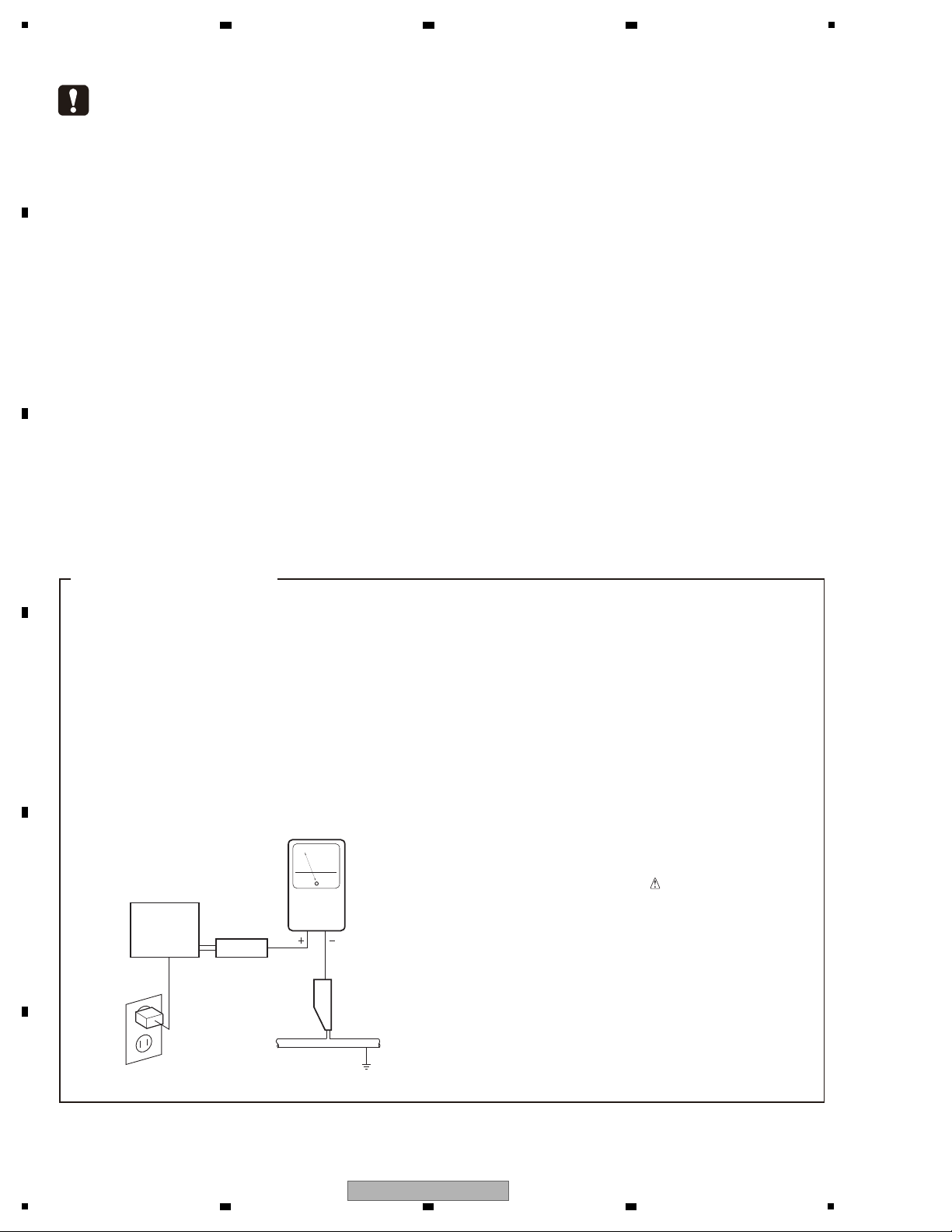
LEAKAGE CURRENT CHECK
Measure leakage current to a known earth ground
(water pipe, conduit, etc.) by connecting a leakage
current tester such as Simpson Model 229-2 or
equivalent between the earth ground and all exposed
metal parts of the appliance (input/output terminals,
screwheads, metal overlays, control shaft, etc.). Plug
the AC line cord of the appliance directly into a 120V
AC 60 Hz outlet and turn the AC power switch on. Any
current measured must not exceed 0.5 mA.
Device
under
test
Leakage
current
tester
Earth
ground
Reading should
not be above
0.5 mA
Also test with
plug reversed
(Using AC adapter
plug as required)
Test all
exposed metal
surfaces
AC Leakage Test
2 3 4
SAFETY INFORMATION
A
B
C
D
E
F
2
1
2 3 4
BDP-05FD
5
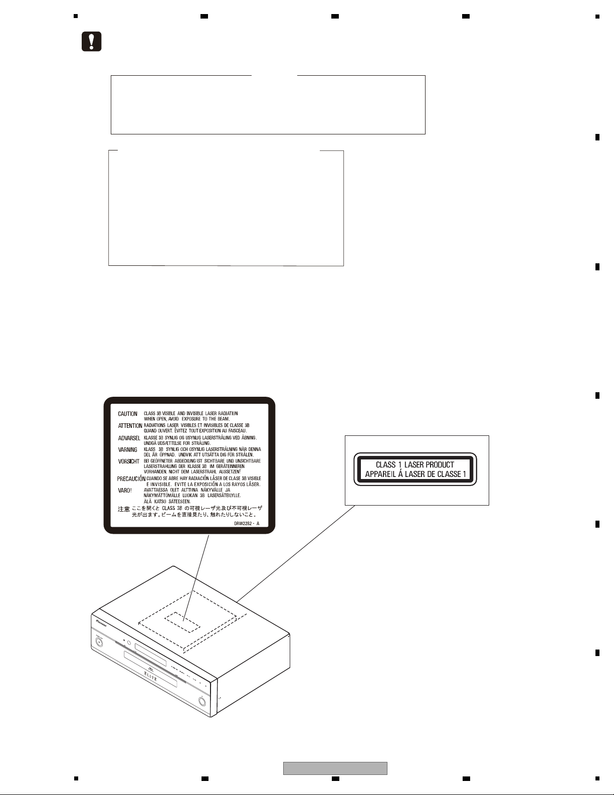
LABEL CHECK
WARNING !
THE LASER COMPONENT IS CAPABLE OF EMITTING RADIATION EXCEEDING THE LIMIT
FOR CLASS 1.
A SPECIALLY INSTRUCTED PERSON SHOULD DO SERVICING OPERATION OF THE
APPARATUS.
(Printed on the Rear Panel)
The following caution label appears on your unit.
Location: inside of the unit
---Laser Pickup specifications and Laser characteristics---
For BD
Wave length : 405 nm
Operating output : 0.95 mW CW, Class 1M
Maximum output : Class 2 (under fault condition)
For DVD
Wave length : 660nm
Operating output : 1.06 mW CW, Class 1M
Maximum output : Class 2M (under fault condition)
For CD
Wave length : 785 nm
Operating output : 1.34 mW CW, Class 1M
Maximum output : Class 1M (under fault condition)
6 7 8
A
B
C
D
E
F
BDP-05FD
5
6 7 8
3
1
2 3 4
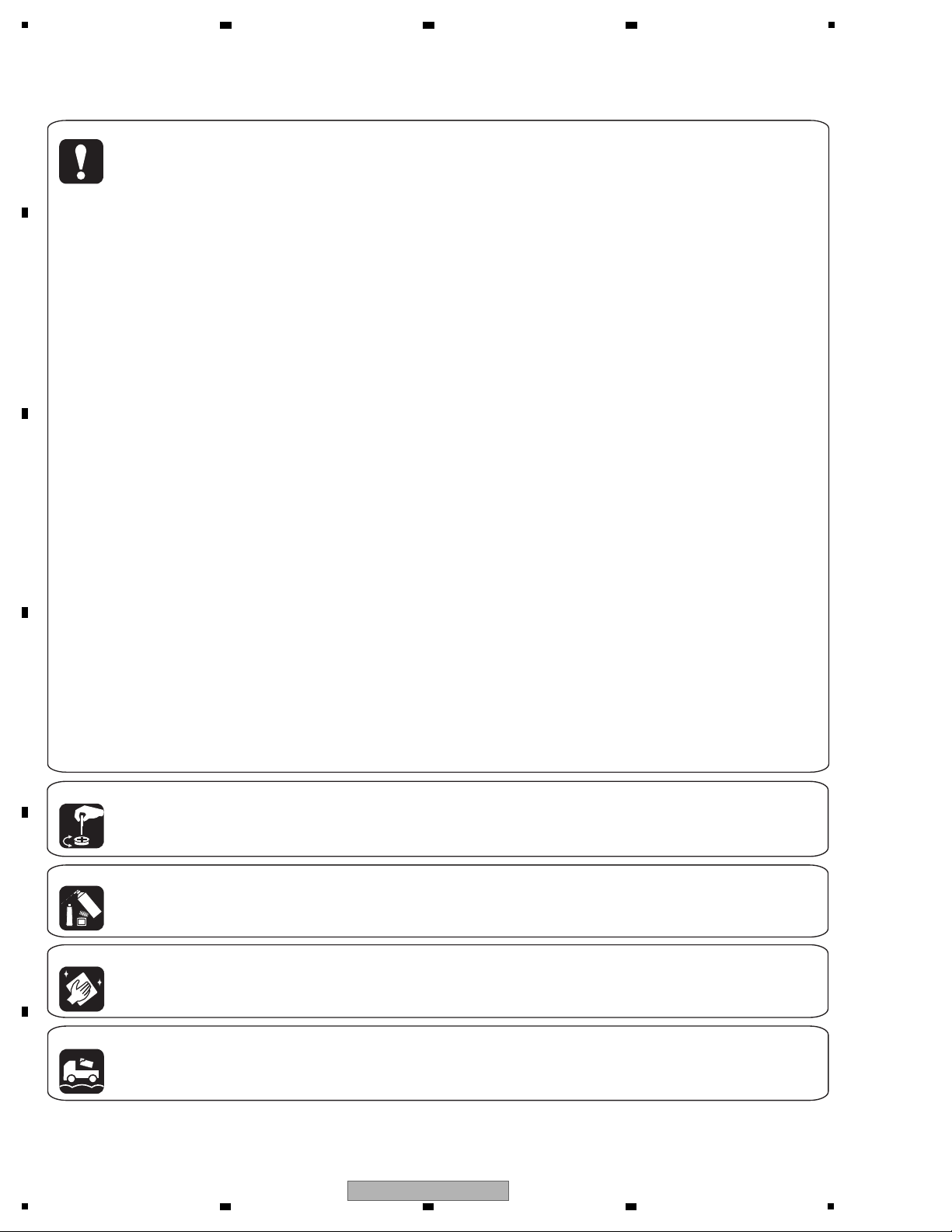
[Important Check Points for Good Servicing]
In this manual, procedures that must be performed during repairs are marked with the below symbol.
Please be sure to confirm and follow these procedures.
A
1. Product safety
Please conform to product regulations (such as safety and radiation regulations), and maintain a safe servicing environment by
following the safety instructions described in this manual.
1 Use specified parts for repair.
Use genuine parts. Be sure to use important parts for safety.
2 Do not perform modifications without proper instructions.
Please follow the specified safety methods when modification(addition/change of parts) is required due to interferences such as
radio/TV interference and foreign noise.
B
C
D
3 Make sure the soldering of repaired locations is properly performed.
When you solder while repairing, please be sure that there are no cold solder and other debris.
Soldering should be finished with the proper quantity. (Refer to the example)
4 Make sure the screws are tightly fastened.
Please be sure that all screws are fastened, and that there are no loose screws.
5 Make sure each connectors are correctly inserted.
Please be sure that all connectors are inserted, and that there are no imperfect insertion.
6 Make sure the wiring cables are set to their original state.
Please replace the wiring and cables to the original state after repairs.
In addition, be sure that there are no pinched wires, etc.
7 Make sure screws and soldering scraps do not remain inside the product.
Please check that neither solder debris nor screws remain inside the product.
8 There should be no semi-broken wires, scratches, melting, etc. on the coating of the power cord.
Damaged power cords may lead to fire accidents, so please be sure that there are no damages.
If you find a damaged power cord, please exchange it with a suitable one.
9 There should be no spark traces or similar marks on the power plug.
When spark traces or similar marks are found on the power supply plug, please check the connection and advise on secure
connections and suitable usage. Please exchange the power cord if necessary.
a Safe environment should be secured during servicing.
When you perform repairs, please pay attention to static electricity, furniture, household articles, etc. in order to prevent injuries.
Please pay attention to your surroundings and repair safely.
2. Adjustments
To keep the original performance of the products, optimum adjustments and confirmation of characteristics within specification.
Adjustments should be performed in accordance with the procedures/instructions described in this manual.
3. Lubricants, Glues, and Replacement parts
Use grease and adhesives that are equal to the specified substance.
E
Make sure the proper amount is applied.
4. Cleaning
For parts that require cleaning, such as optical pickups, tape deck heads, lenses and mirrors used in projection monitors, proper
cleaning should be performed to restore their performances.
5. Shipping mode and Shipping screws
To protect products from damages or failures during transit, the shipping mode should be set or the shipping screws should be
installed before shipment. Please be sure to follow this method especially if it is specified in this manual.
F
4
1
BDP-05FD
2 3 4

5
6 7 8
CONTENTS
SAFETY INFORMATION.......................................................................................................................................................... 2
1. SERVICE PRECAUTIONS....................................................................................................................................................6
1.1 NOTES ON SOLDERING...............................................................................................................................................6
2. SPECIFICATIONS................................................................................................................................................................. 7
2.1 ACCESSORIES.............................................................................................................................................................. 7
2.2 SPECIFICATIONS .......................................................................................................................................................... 8
2.3 DISC/CONTENT FORMAT ...........................................................................................................................................10
2.4 PANEL FACILITIES....................................................................................................................................................... 13
3. BASIC ITEMS FOR SERVICE ............................................................................................................................................ 16
3.1 CHECK POINTS AFTER SERVICING .........................................................................................................................16
3.2 PCB LOCATIONS.........................................................................................................................................................17
3.3 JIGS LIST ..................................................................................................................................................................... 18
4. BLOCK DIAGRAM ..............................................................................................................................................................20
4.1 OVERALL WIRING DIAGRAM .....................................................................................................................................20
4.2 BLOCK DIAGRAM........................................................................................................................................................22
4.3 POWER BLOCK DIAGRAM ......................................................................................................................................... 23
5. DIAGNOSIS ........................................................................................................................................................................ 25
5.1 POWER ON SEQUENCE.............................................................................................................................................25
5.2 RESET ON SEQUENCE ..............................................................................................................................................26
6. SERVICE MODE................................................................................................................................................................. 28
6.1 OSD .............................................................................................................................................................................. 28
7. DISASSEMBLY ................................................................................................................................................................... 44
8. EACH SETTING AND ADJUSTMENT................................................................................................................................51
8.1 NECESSARY ADJUSTMENT POINTS ........................................................................................................................51
8.2 MODEL SETTING ........................................................................................................................................................ 52
8.3 CPRM ID NUMBER AND DATA SETTING ................................................................................................................... 54
8.4 FIRMWARE UPDATE ................................................................................................................................................... 57
9. EXPLODED
9.1 PACKING SECTION .....................................................................................................................................................58
9.2 EXTERIOR SECTION .................................................................................................................................................. 60
9.3 FRONT PANEL SECTION ............................................................................................................................................62
10. SCHEMATIC DIAGRAM.................................................................................................................................................... 64
10.1 MAIN ASSY (1/10)......................................................................................................................................................64
10.2 MAIN ASSY (2/10)......................................................................................................................................................68
10.3 MAIN ASSY (3/10)......................................................................................................................................................72
10.4 MAIN ASSY (4/10)......................................................................................................................................................74
10.5 MAIN ASSY (5/10)......................................................................................................................................................76
10.6 MAIN ASSY (6/10)......................................................................................................................................................78
10.7 MAIN ASSY (7/10)......................................................................................................................................................80
10.8 MAIN ASSY (8/10)......................................................................................................................................................84
10.9 MAIN ASSY (9/10)......................................................................................................................................................86
10.10 MAIN ASSY (10/10).................................................................................................................................................. 88
10.11 FLKY ASSY (BDP-05FD) ......................................................................................................................................... 92
10.12 FLKY ASSY (BDP-51FD) ......................................................................................................................................... 94
10.13 PSWB ASSY.............................................................................................................................................................96
10.15 AUJB ASSY (1/2)......................................................................................................................................................98
10.16 AUJB ASSY (2/2)....................................................................................................................................................100
10.14 CAPK ASSY .............................................................................................................................................................97
10.17 SYPS ASSY............................................................................................................................................................102
10.18 W
11. PCB CONNECTION DIAGRAM ......................................................................................................................................107
11.1 MAIN ASSY ..............................................................................................................................................................108
11.2 FLKY, CAPK and PSWB ASSYS.............................................................................................................................. 112
11.3 AUJB ASSY .............................................................................................................................................................. 116
11.4 SYPS ASSY..............................................................................................................................................................118
12. PCB PARTS LIST............................................................................................................................................................120
VIEWS AND PARTS LIST............................................................................................................................... 58
A
VEFORMS......................................................................................................................................................... 104
A
B
C
D
E
F
BDP-05FD
5
6 7 8
5

1
Be sure to use lead-free solder and a soldering iron that can meet specifications for use with lead-free solders for repairs
accompanied by reworking of soldering.
Therefore, for lead-free soldering, the tip temperature of a soldering iron must be set to around 373 ºC in general, although
the temperature depends on the heat capacity of the PC board on which reworking is required and the weight of the tip of
the soldering iron.
GYP1006 1.0 in dia.
GYP1007 0.6 in dia.
GYP1008 0.3 in dia.
2 3 4
1. SERVICE PRECAUTIONS
1.1 NOTES ON SOLDERING
A
B
C
D
E
F
6
1
BDP-05FD
2 3 4
5
STANDBY/ON
OPEN/CLOSE
AUDIO
SUBTITLE
ANGLE
FL DIMMER
CLEAR
ENTER
VIDEO SELECT
PLAY MODE
HOME MEDIA
GALLERY
MENU
DISPLAY POPUP MENU
TOP MENU
TOOLS
HOME
MENU
RETURN
BD PLAYER
PLAY
PREV
PAUSE
STOP
NEXT
RED
GREEN
YELLOWBLUE
VIDEO ADJUST
INPUT
SELECT
TV CON TROL
CH
VOL
AUDIO
VIDEO
SECONDARY
OUTPUT
RESOLUTION
ENTER
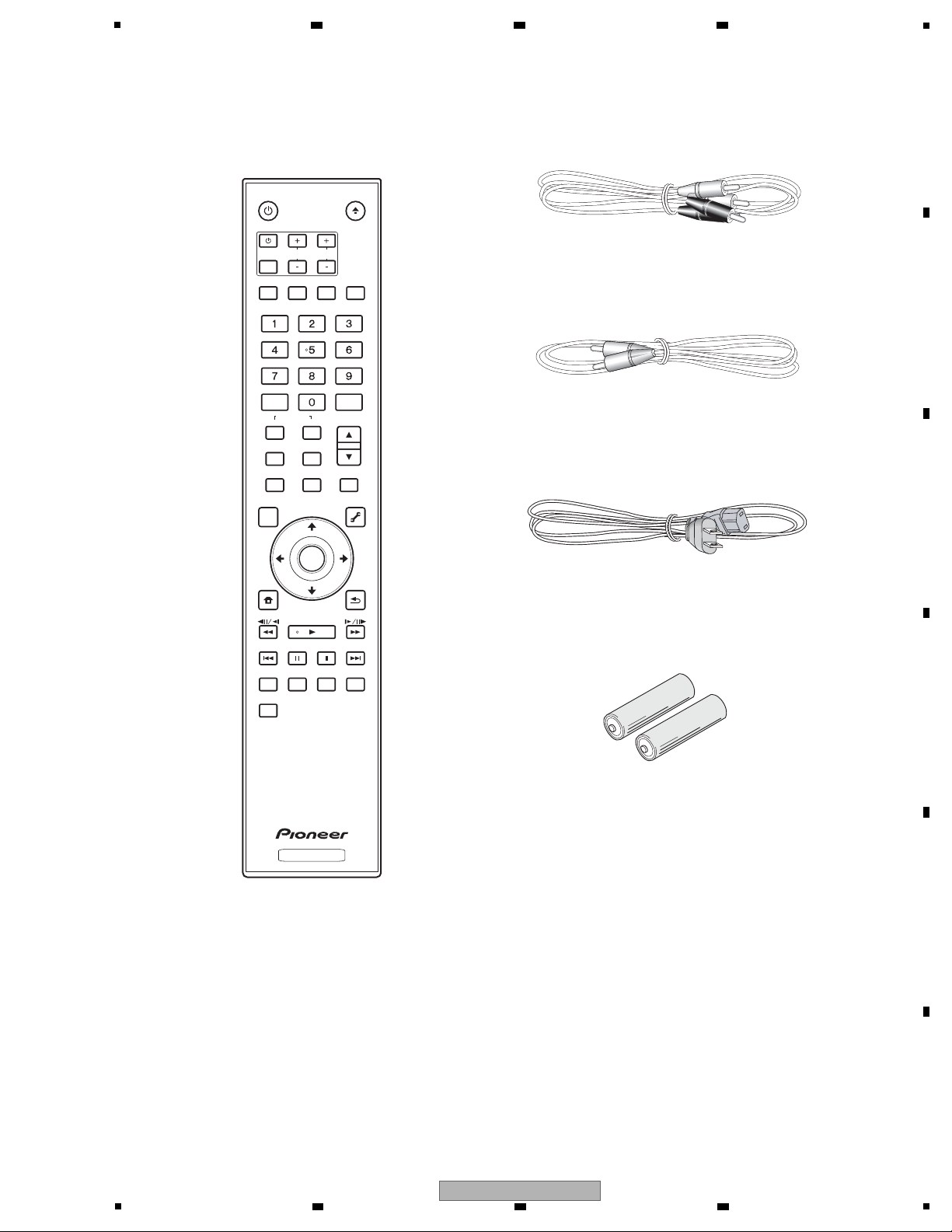
(VDE1064) L=1.5m
(VDE1065) L=1.5m
( ADG7061 )
( BDP-05FD : VRB1502 )
( BDP-51FD : VRB1505 )
Remote Control
( BDP-05FD : VXX3313)
( BDP-51FD : VXX3333)
AA/R6 dry cell batteries
Warranty Card
Operating Instructions
Audio cable (white/red) x 1
Video cable (yellow) x 1
Power cable x 1
2. SPECIFICATIONS
2.1 ACCESSORIES
6 7 8
A
B
C
D
E
F
BDP-05FD
5
6 7 8
7

1
Note
• The specifications and design of this product are subject to
change without notice.
• This product includes FontAvenue
®
fonts licensed by NEC
Corporation. FontAvenue is a registered trademark of NEC
Corporation.
Model BDP-05FD
Type Blu-ray Disc PLAYER
Rated voltage AC 120 V
Rated frequency 60 Hz
Power consumption 37 W
Power consumption (standby) 0.5 W
Weight 5.7 kg (12 lb 10 oz)
External dimensions (including projecting parts) 420 mm (W) x 124 mm (H) x 360 mm (D)
(16
9
/16 in. (W) x 4 15/16 in. (H) x 14 3/16 in. (D))
Tolerable operating temperature +5 °C to +35 °C (+41 °F to +95 °F)
Tolerable operating humidity 5 % to 85 % (no condensation)
Output terminals
Video outputs Video 1 set, RCA jack (1.0 Vp-p (75 Ω))
S-Video 1 set, S-Video jack:
Y (luminance): 1.0 Vp-p (75 Ω)
C (color): 0.286 Vp-p (75 Ω)
Component video 1 set, pin-plug jacks:
Y: 1.0 Vp-p (75 Ω)
P
B, PR: 0.7 Vp-p (75 Ω)
HDMI 1 set, 19-pin (5V, 150 mA)
Audio outputs 2-channel (stereo) Number of channels: 2, RCA jacks
7.1-channel (multi-channel: front left/
right, surround left/right, center,
surround back left/right, subwoofer)
Number of channels: 8, RCA jacks
Audio output level 200 mVrms (1 kHz, –20 dB)
Frequency response 4 Hz to 88 kHz (192 kHz sampling)
S/N ratio 115 dB
Dynamic range 103 dB
Total harmonic distortion 0.0015 %
Wow & flutter Below measurable limits (±0.001 % W. PEAK)
Digital audio outputs Optical 1 set, Optical digital jack
Coaxial 1 set, RCA jack
Control Input 1 set, Minijack (3.5 ø)
2.2 SPECIFICATIONS
A
B
C
D
2 3 4
E
F
8
1
2 3 4
BDP-05FD

5
Note
• The specifications and design of this product are subject to
change without notice.
• This product includes FontAvenue
®
fonts licensed by NEC
Corporation. FontAvenue is a registered trademark of NEC
Corporation.
Model BDP-51FD
Type Blu-ray Disc PLAYER
Rated voltage AC 120 V
Rated frequency 60 Hz
Power consumption 34 W
Power consumption (standby) 0.5 W
Weight 5.6 kg (12 lb 6 oz)
External dimensions (including projecting parts) 420 mm (W) x 124 mm (H) x 361 mm (D)
(16
9
/16 in. (W) x 4 15/16 in. (H) x 14 1/4 in. (D))
Tolerable operating temperature +5 °C to +35 °C (+41 °F to +95 °F)
Tolerable operating humidity 5 % to 85 % (no condensation)
Output terminals
Video outputs Video 1 set, RCA jack (1.0 Vp-p (75 Ω))
S-Video 1 set, S-Video jack:
Y (luminance): 1.0 Vp-p (75 Ω)
C (color): 0.286 Vp-p (75 Ω)
Component video 1 set, pin-plug jacks:
Y: 1.0 Vp-p (75 Ω)
PB, PR: 0.7 Vp-p (75 Ω)
HDMI 1 set, 19-pin (5V, 150 mA)
Audio outputs 2-channel (stereo) Number of channels: 2, RCA jacks
7.1-channel (multi-channel: front left/
right, surround left/right, center,
surround back left/right, subwoofer)
Number of channels: 8, RCA jacks
Audio output level 200 mVrms (1 kHz, –20 dB)
Frequency response 4 Hz to 88 kHz (192 kHz sampling)
S/N ratio 115 dB
Dynamic range 103 dB
Total harmonic distortion 0.0015 %
Wow & flutter Below measurable limits (±0.001 % W. PEAK)
Digital audio outputs Optical 1 set, Optical digital jack
Coaxial 1 set, RCA jack
Control Input 1 set, Minijack (3.5 ø)
6 7 8
A
B
C
D
5
BDP-05FD
6 7 8
E
F
9
1
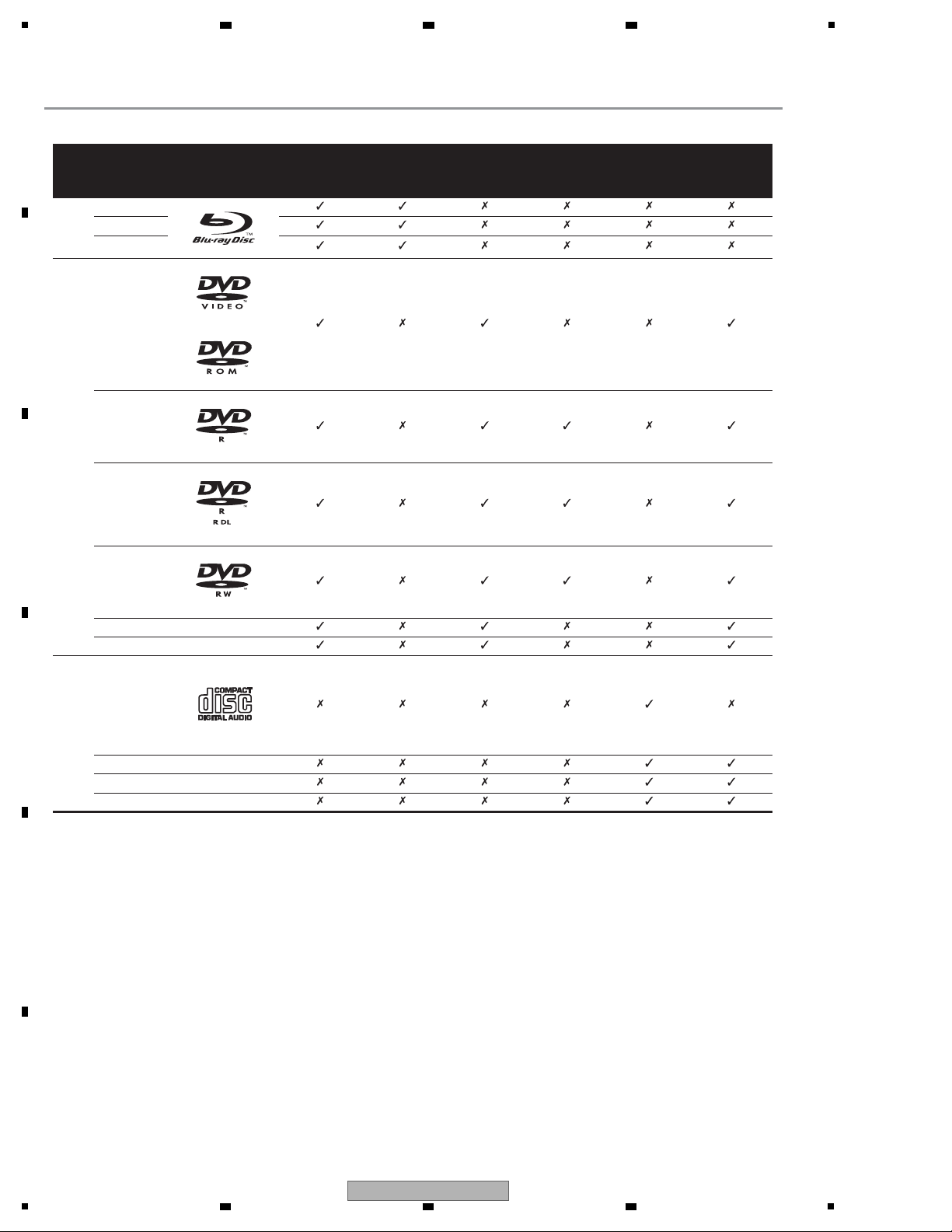
Disc type
Logo Application format
BDMV
1
1. Including the AVCHD format.
BDAV DVD-Video DVD VR
CD-DA
DTS-CD
DATA-DISC
2
2. Discs on which music files are recorded
BD
BD-ROM
BD-R
BD-RE
DVD
DVD-ROM
DVD-R
DVD-R DL
(Dual Layer)
DVD-RW
DVD+R
DVD+RW
CD
CD-DA
(Music CD)
CD-R
CD-RW
CD-ROM
2.3 DISC/CONTENT FORMAT
A
B
2 3 4
C
D
E
F
10
1
2 3 4
BDP-05FD
5
Discs that cannot be played
•HD DVDs
•DVD Audio discs
•DVD-RAM discs
• Non-finalized DVD-R/DVD-RW/DVD+R/DVD+RW discs in the
DVD-Video format and AVCHD format
• Non-finalized Dual Layer DVD-R discs in the DVD VR format
•SACDs
• Video CDs
•SVCDs
This player conforms to NTSC standards. Discs for which “NTSC” is
indicated on the disc label, package or jacket can be played.
“Blu-ray Disc” and are trademarks.
is a trademark of DVD Form at/Logo Licensing Corporation.
Note
• Some discs cannot be played, even if one of the above logo
marks is indicated.
• To play 8 cm discs, set the disc in the 8 cm disc depression in
the center of the disc tray. No adapter is necessary. 8 cm BDROMs cannot be played.
About audio formats
The following audio formats are supported on this player:
•Dolby TrueHD
• Dolby Digital Plus
•Dolby Digital
• DTS-HD Master Audio
• DTS-HD High Resolution Audio
• DTS Digital Surround
•MPEG
• MPEG-2 AAC
• Linear PCM
To enjoy the surround sound of Dolby TrueHD, Dolby Digital Plus,
DTS-HD Master Audio and DTS-HDHigh Resolution Audio, it is
recommended to connect the player to an AV receiver or amplifier
compatible with these audio formats using an HDMI cable. After
loading a BD containing sound in one of these audio formats, select
the audio format on the menu screen.
Manufactured under license from Dolby Laboratories. Dolby and the
double-D symbol are trademarks of Dolby Laboratories.
Manufactured under license under U.S. Patent #: 5,451,942;
5,956,674; 5,974,380; 5,978,762; 6,487,535 & other U.S. and worldwide
patents issued & pending. DTS isa registered trademark and the DTS
logos, Symbol, DTS-HD and DTS-HD Advanced Digital Out are
trademarks of DTS, Inc. © 1996-2007 DTS, Inc. All Rights Reserved.
Playing BDs
•BDs (BDMV) compatible with th e formats below can be played.
– Blu-ray Disc Read-Only (ROM) Format Version 2
– Blu-ray Disc Recordable (R) Format Version 2
– Blu-ray Disc Rewritable (RE) Format Version 3
This player supports BD-ROM Profile 1 Version 1.1.
BONUSVIEW Functions such as playback of secondary video
(Picture-in-Picture) and secondary audio can be used. For
details on secondary video and secondary audio playback, refer
to the disc’s instructions.
“BONUSVIEW” is trademark of Blu-ray Disc Association.
When a BD-ROM is played, additional data may be stored in the
player’s memory area (local storage). If the message indicating
low memory (local storage) appears, erase the BDMV data.
• BDs (BDAV) compatible with the formats below can be played.
– Blu-ray Disc Recordable (R) Format Version 1
– Blu-ray Disc Rewritable (RE) Format Version 2
• Dual Layer BDs can be played.
• Music files recorded on BDs cannot be played.
• 8 cm BD-ROMs cannot be played.
6 7 8
A
B
C
D
E
F
BDP-05FD
5
6 7 8
11
1
Playing DVDs
•DVD-Video can be played.
•DVD-R/-RW/+R/+RW discs recorded in the DVD-Video format
can be played (finalize them before playing them on this player).
•DVD-R/-RW discs recorded in the VR format (Video Recording
format) can be played.
• This label indicates playback compatibility with DVD-RW discs
recorded in VR format (VideoRecording format). However, for
discs recorded with a record-only-once encrypted program,
playback can only be achieved using a CPRM compatible
device.
•DVDs recorded in the AVCHD format can be played (finalize
them before playing them on this player).
“AVCHD” and the “AVCHD” logo are trademarks of Matsushita
Electric Industrial Co., Ltd. and Sony Corporation.
• Music files recorded on DVD-R/-RW/+R/+RW discs can be
played.
• Dual Layer DVDs can be played. However, Non-finalized Dual
Layer DVD-R discs recorded in the VR format cannot be played
(finalize them before playing them on this player).
•HD DVD, DVD Audio and DVD-RAM discs cannot be played.
About region numbers
Blu-ray Disc Player and BD-ROM or DVD-Video discs are assigned
region numbers according to the region in which they are sold.
This player’s region numbers are:
•BD-ROM: A
•DVD-Video: 1
Discs not including these numbers cannot be played. Discs
playable on this player are as shown below.
• BDs: A (including A) and ALL
•DVDs: 1 (including 1) and ALL
Playing CDs
• Music CDs (CD-DAs and DTS-CDs) can be played.
• Music files recorded on CDs can be played.
• SACD, Video CD and Super VCD discs cannot be played.
• Regarding copy protected CDs: This player is designed to
conform to the specifications of the Audio CD format. This
player does not support the playback or function of discs that do
not conform to these specifications.
DualDisc playback
A DualDisc is a new two-sided disc, one side of which contains DVD
content — video, audio, etc. — while the other side contains nonDVD content such as digital audio material.
The DVD side of a DualDisc will be played on this player (excluding
any DVD-Audio content).
The non-DVD, audio side of the disc is not compatible with this
player.
It is possible that when loading or ejecting a DualDisc, the opposite
side to that being played will be scratched. Scratched discs may not
be playable.
For more detailed information on the DualDisc specification, please
refer to the disc manufacturer or disc retailer.
Playing discs created on computers
• It may not be possible to play DVD-R/-RW or CD-R/-RW discs
recorded using a personal recorder or computer. (This can be
due to various reasons, including disc properties, scratches, dirt
on the disc, dirt on the player’s lens, condensation and so on.)
• It may not be possible to play discs recorded using a computer
due to the application settings or environment. Record discs in
the proper format. For details, contact the dealer.
Playable files
Music files recorded on DVDs and CDs can be played.
Caution
•In DVD, only the one recorded by the ISO 9660 file system can be
played.
• Some files may not be playable.
• For some files, it may not bepossible to use certain functions
during playback.
• It may not be possible to play some files, even if they have the
extension of a file playable on this player.
• Files protected by DRM (Digital Rights Management) cannot be
played.
Supported music file formats
• Windows Media™ Audio 9 (WMA9)
Bit rate: Up to 192 kbps
Sampling frequencies: 22.05 kHz, 32 kHz, 44.1 kHz and 48 kHz
• MPEG-1 Audio Layer 3 (MP3)
Bit rate: Up to 320 kbps
Sampling frequencies: 8 kHz, 11.025 kHz, 12 kHz, 16 kHz,
22.05 kHz, 24 kHz, 32 kHz, 44.1 kHz and 48 kHz
Playable file extensions
• Music files
.wma and .mp3
• Windows Media is either a registered trademark or trademark of
Microsoft Corporation in the United States and/or other countries.
• This product includes technology owned by Microsoft Corporation
and cannot be used or distributed without a license from
Microsoft Licensing, Inc.
A
2 3 4
B
C
D
E
F
12
1
2 3 4
BDP-05FD
2.4 PANEL FACILITIES
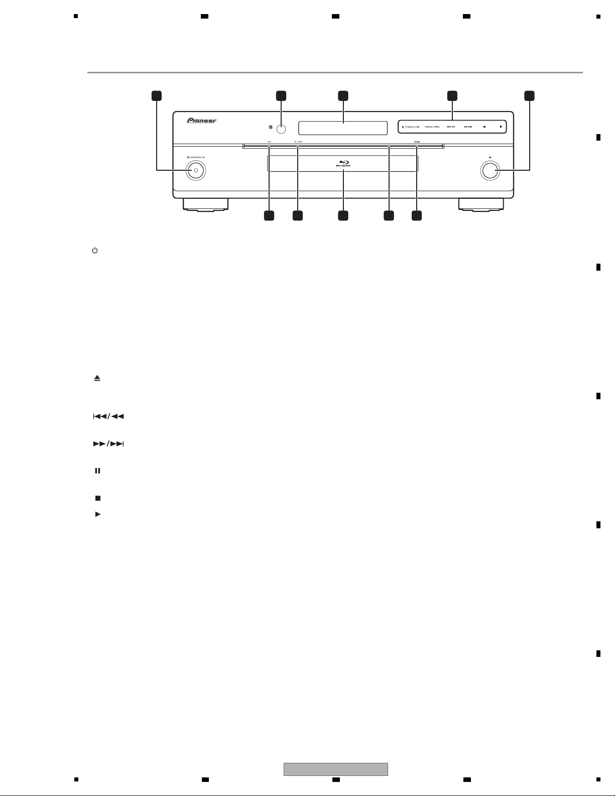
Front Panel
1 STANDBY/ON
Press to turn the power on and off.
2 Remote control sensor
Point the remote control to this, then operate it within approximately
23 feet.
The player may have trouble capturing remote control signals if
there is a fluorescent light nearby. If this happens, move the player
away from the fluorescent light.
3 Front panel display
4 Touch sensor – Touch the center of the words or marks lightly
to operate.
OPEN/CLOSE – Press to open and close the disc tray.
RESOLUTION – Press to switch the output video resolution from
the HDMI output or component video output terminals.
– Press to skip to the beginning of the previous title/
chapter/track/file. Press and hold to start reverse scanning.
– Press to skip to the beginning of the next title/
chapter/track/file. Press and hold to start forward scanning.
– Press during playback to pause. Press again to restrart
playback.
– Press to stop playback.
5
Press to start playback.
6 HDMI indicator
This lights when an HDMI-compatible device is connected.
7 Touch sensor indicator
This lights when the touch sensor is touched.
8 Disc tray
9 FL OFF indicator
This lights when Off is selected with FL DIMMER.
10 HD indicator
This lights when an HDMI cable is connected and video signals are
being output with a resolution of 1080/60i, 1080/60p, 1080/24p or
720/60p. It also lights when a component video cable is connected
and video signals are being output with a resolution of 1080/60i or
720/60p.
1 5
2 3 4
68 7910
(BDP-05FD)
5
6 7 8
A
B
C
D
E
BDP-05FD
5
6 7 8
F
13
1
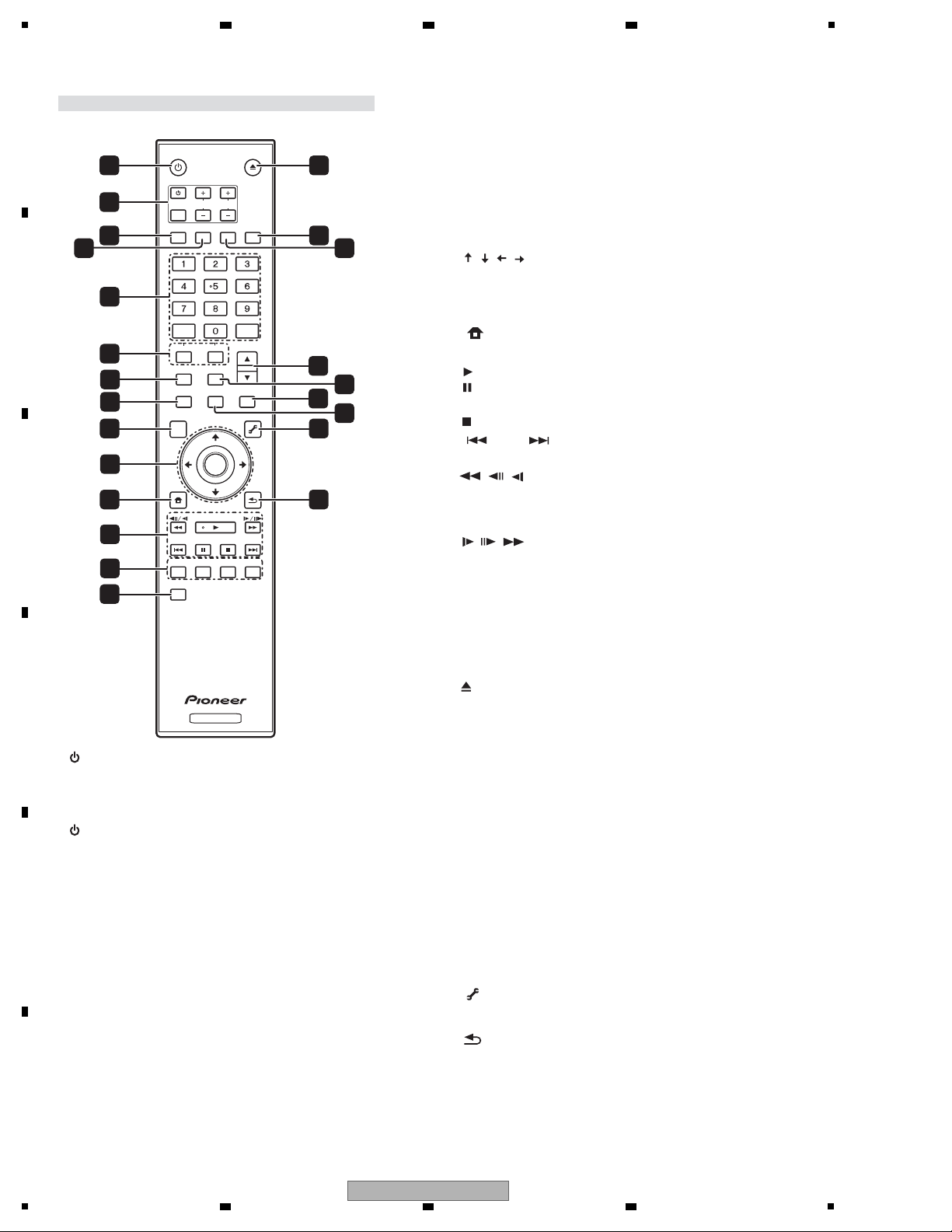
1 STANDBY/ON
Press to turn the power on and off.
2 TV CONTROL
Your TV can be controlled using the player’s remote control.
– Press to turn the TV’s power on and off.
INPUT SELECT – Press to switch the TV’s input.
CH +/– – Press to select the TV channel.
VOL +/– – Press to adjust the volume.
3 AUDIO
Press to switch the audio streams/channels.
4 SUBTITLE
Press to switch the subtitles.
5 Number buttons – Use these to select and play the title/
chapter/track you want to watch or listen to and to select items
from menus.
CLEAR – Press to clear the numeric number, etc.
ENTER – Press to execute the selected item or enter a setting
that has been changed, etc.
6 SECONDARY AUDIO – When playing a BD-ROM on which
secondary audio is recorded, press to switch to the secondary
audio.
SECONDARY VIDEO – When playing a BD-ROM on which
secondary video (Picture-in-Picture) is recorded, press to switch
to the secondary video.
7 VIDEO SELECT
Press to switch the terminal from which the video signals are
output. Use to switch between digital output (HDMI output) and
analog output (Component Video output, S-Video output or Video
output) (the signals are only output from the selected video
output terminal).
8 HOME MEDIA GALLERY
Press to display/hide the HomeMedia Gallery screen.
9TOP MENU
Press to display the top menu of the BD-ROM or DVD-Video.
10 / / / – Use to select items, change settings and move
the cursor.
ENTER – Press to execute the selected item or enter a setting
that has been changed, etc.
11 HOME MENU
Press to display/hide the Home Menu.
12 PLAY – Press to start playback.
PAUSE – Press to pause playback. Press again to restart
playback.
STOP – Press to stop playback.
PREV/ NEXT – Press to skip to the beginning of the
previous/next title/chapter/track/file.
// – Press during playback to start reverse scanning.
While playback is paused, press for step reverse playback. Press
and hold while playback is paused for reverse slow motion
playback.
// – Press during playback to start forward scanning.
While playback is paused, press for step forward playback.
Press and hold while playback is paused for forward slow
motion playback.
13 RED/GREEN/BLUE/YELLOW
Use these to navigate BD-ROM menus.
14 VIDEO ADJUST
Press to display/hide the Video Adjust menu.
15
OPEN/CLOSE
Press to open and close the disc tray.
16
FL DIMMER
Press to switch the brightness of the front panel display. The FL OFF
indicator lights when Off is selected.
17 ANGLE
Press to switch the BD-ROM or DVD-Video camera angles.
18 OUTPUT RESOLUTION
Use these to switch the output video resolution from the HDMI OUT
or COMPONENT VIDEO output terminals.
19 PLAY MODE
Press to display/hide the Play Mode screen.
20 POP UP MENU/MENU
Press to display the BD-ROM or DVD-Video menus.
21 DISPLAY
Press to display disc information.
22 TOOLS
Press to display/hide the TOOLS menu.
23 RETURN
Press to return to the previous screen.
Remote control unit
STANDBY/ON
OPEN/CLOSE
AUDIO
SUBTITLE
ANGLE
FL DIMMER
CLEAR
ENTER
VIDEO SELECT
PLAY MODE
HOME MEDIA
GALLERY
MENU
DISPLAY POPUP MENU
TOP MENU
TOOLS
HOME
MENU
RETURN
BD PLAYER
PLAY
PREV
PAUSE
STOP
NEXT
RED
GREEN
YELLOWBLUE
VIDEO ADJUST
INPUT
SELECT
TV CONTROL
CH
VOL
AUDIO
VIDEO
SECONDARY
OUTPUT
RESOLUTION
ENTER
10
7
8
4
12
13
1
2
3
5
6
9
11
14
18
20
17
19
21
15
16
22
23
A
2 3 4
B
C
D
E
F
14
1
2 3 4
BDP-05FD
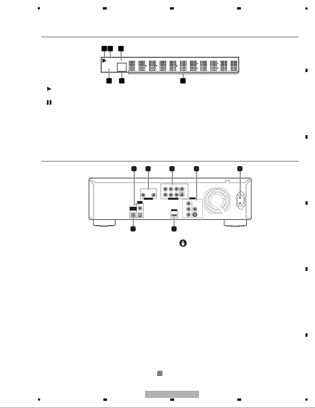
Front Panel Display
1
Lights during playback.
2
Lights when the pause mode is set.
3PQLS
Lights when the PQLS function is activated.
4 Counter display
Displays the title/chapter/track number, elapsed time, etc.
5 24HZ/50HZ/60HZ
The frequency of the video frame or field being output lights.
6CONTROL
Lights when the “HDMI Control” function is activated.
Rear Panel
PQLS
24HZ
50HZ
60HZ
CONTROL
4
1 2563
R
R
AUDIO OUT (2 ch) AUDIO OUT (7.1 ch)
VIDEO OUT
HDMI OUT
DIGITAL
OUT
CONTROL
IN
L
L
Y
P
B
PR
FRONT
COAXIAL
OPTICAL
COMPONENT VIDEO
AC IN
SURROUND
CENTER
VIDEO
S-VIDEO
SUB WOOFER
SURROUND
BACK
1 2 3 4 5
67
1 DIGITAL OUT (COAXIAL/OPTICAL)
Connect with the digital audio input terminal on an AV receiver or
amplifier, etc.
2 AUDIO OUT (2 ch) terminals
Connect with the audio input terminals on a TV, AV receiver or
amplifier, etc.
3 AUDIO OUT (7.1 ch) terminals
Connect with the multi-channel (7.1- or 5.1-channel) audio input
terminals on an AV receiver or amplifier, etc.
4 VIDEO OUT terminals
VIDEO – Connect with the video input terminal on a TV, AV
receiver or amplifier, etc.
S-VIDEO – Connect with the S-Video input terminal on a TV, AV
receiver or amplifier, etc.
COMPONENT VIDEO – Connect with the component video
input terminals on a TV, AV receiver or amplifier, etc.
5 AC IN
Connect the power cord here.
6 HDMI OUT terminal
Connect with an HDMI-compatible TV, AV receiver or amplifier, etc.
7 CONTROL IN terminal
Use to control this player from the remote sensor of another Pioneer
component with a CONTROL OUT terminal and bearing the
mark. Connect the CONTROL OUT of the other component to the
CONTROL IN of this player using a mini-plug cord.
Caution
• Be sure to connect cables for outputting the audio and video
signals.
• When connected via System Control, point the remote control
toward the connected component (such as an AV receiver or
amplifier). The remote will not work correctly when pointed at
this player.
• You cannot use System Control with components that do not
have a System Control terminal or with components
manufactured by companies other than Pioneer.
5
6 7 8
A
B
C
D
5
BDP-05FD
6 7 8
E
F
15
1
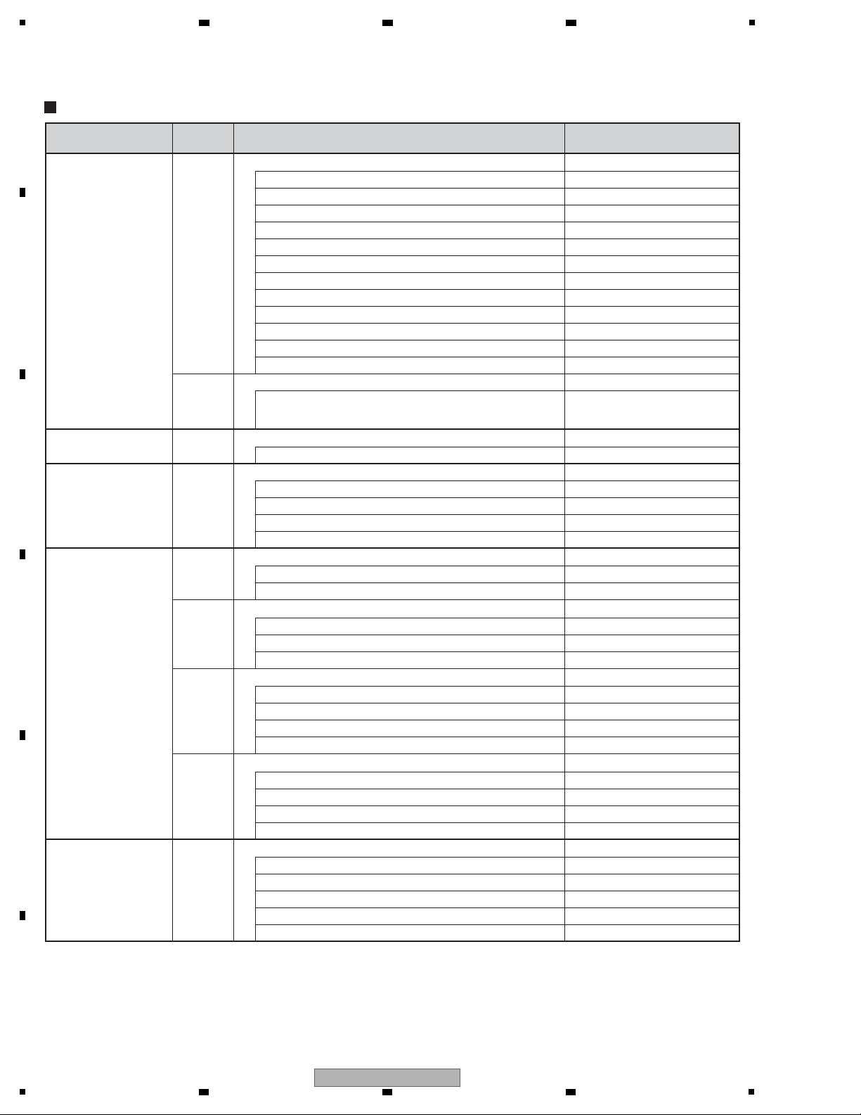
Items to be checked after repair (BD players)
To ensure the quality of the product after repair, check the recommended items shown below:
See the table below for the items to be checked regarding video and audio:
Item to be checked regarding video Item to be checked regarding audio
Block noise Distortion
Horizontal noise Noise
Dot noise Volume too low
Disturbed image (video jumpiness) Volume too high
Too dark Volume fluctuating
Too bright Sound interrupted
Mottled color
Color disappearance
No. Procedures Item to be checked
1 Check the version of the firmware in Service mode.
The version must be the latest.
If the version is not the latest, update the firmware.
2
Check if all the symptoms pointed out by the customer have been
addressed. If a symptom pointed out by the customer is
attributable to a particular disc, that disc must be played back.
The symptoms in question must not be reproduced.
Video, audio, and operations must be normal.
3
Measure playback error rates at the innermost and outermost
tracks, by playing back the following discs:
BD-ROM test disc (GGV1308)
DVD test disc (GGV1025)
The error rates must be 1.0e-3 or less.
This procedure can determine if the drive is degraded.
4 Check playback of a CD disc (track search). Audio and operations, such as a search, must be normal.
5
Check playback of a DVD disc (menu operations, title/chapter
search).
Video, audio, and operations, such as a search, must be normal.
6
Check playback of a BD disc (menu operations, title/chapter
search).
Video, audio, and operations, such as a search, must be normal.
7 Check the cabinet.
Check for any scratches or dirt that have been made or attached
on the cabinet after receiving the product for repair.
Before shipping out the product, be sure to clean the following positions by using the prescribed cleaning tools:
Position to be cleaned Cleaning tools
Pickup lenses Cleaning liquid : GEM1004
Cleaning paper : GED-008
Position to be cleaned Cleaning tools
Fans Cleaning paper : GED-008
Cleaning
2 3 4
3. BASIC ITEMS FOR SERVICE
3.1 CHECK POINTS AFTER SERVICING
A
B
C
D
E
F
16
1
2 3 4
BDP-05FD
5
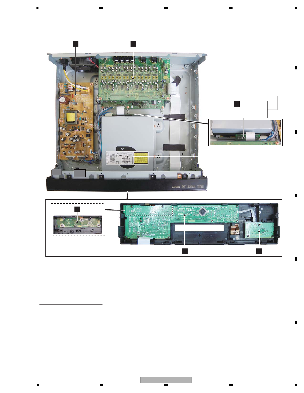
3.2 PCB LOCATIONS
SYPS ASSY
G
6 7 8
AUJB ASSY
D
A
F
BDP-05FD ONLY
CAPK ASSY
SERVICE MAIN ASSY
MAIN ASSY
A
ATAB ASSY
DRIVE ASSY BDV-103
B
C
D
FLKY ASSY
B
PSWB ASSY
C
NOTES: - Parts marked by “NSP” are generally unavailable because they are not in our Master Spare Parts List.
-
The > mark found on some component parts indicates the importance of the safety factor of the part.
Therefore, when replacing, be sure to use parts of identical designation.
Mark No. Description Part No. Mark No. Description Part No.
LIST OF ASSEMBLIES
1..CAPK ASSY (BDP-05FD only) VWG2614
NSP 1..AUJB ASSY (BDP-05FD) VWG2615
NSP 1..AUJB ASSY (BDP-51FD) VWG2632
NSP 1..FLKB ASSY (BDP-05FD) VWM2463
NSP 1..FLKB ASSY (BDP-51FD) VWM2481
2..FLKY ASSY (BDP-05FD) VWG2612
2..FLKY ASSY (BDP-51FD) VWG2625
2..PSWB ASSY VWG2613
5
6 7 8
1..SERVICE MAIN ASSY
1..SERVICE MAIN ASSY
NSP 2..MAIN ASSY (BDP2.0)
NSP 2..MAIN ASSY (BDP2.0)
2..ATAB ASSY (BDP2.0) VWV2360
> 1..SYPS ASSY VWR1415
1..DRIVE ASSY BDV-103 VXX3325
BDP-05FD
(BDP-05FD)
(BDP-51FD)
(BDP-05FD)
(BDP-51FD)
VXX3326
VXX3328
VWV2315
VWV2375
E
F
17

1
Service Remote Control Unit GGF1067
DVD Test Disc (DVD-Video)
BD-ROM Test Disc
GGV1324
Adjustment, diagnosis
Name Jig No. Remarks
Check of DVD-Video
Check of BD-ROM
ID Data Disc for Blu-ray player Type 2 Vol 1.0
GGV1025
GGV1308
Diagnosis (ID data setting)
Jigs List
Disc Ejection Rod
GGF1529 Emergency Disc Ejection
3.3 JIGS LIST
A
B
2 3 4
C
D
E
F
18
1
2 3 4
BDP-05FD

5
6 7 8
A
B
C
D
E
F
BDP-05FD
5
6 7 8
19
1
RESET#
GND
DD7
DD8
DD6
DD9
DD5
DD10
DD4
DD11
DD3
DD12
DD2
DD13
DD1
DD14
DD0
DD15
GND
KEYPIN
DMARQ
GND
DIOW#
GND
DIOR#
GND
IORDY
CSEL
DMACK#
GND
INTRQ
RESERVED
DA1
PDIAG#
DA0
DA2
CS0#
CS1#
DASP#
GND
SW+5V_W
GND
GND
SW+12V_W
GND
SW-23V
GND
SW+12V
GND
P_ON
EV+6V
SW+2.5V
GND
GND
SW+1.5V
SW+1.5V
GND
GND
GNDA
SW+12A
SW+2.5V
GND
GND
SW+5V
SW+5V
GND
GNDA
SW-12A
GND
DASP#
CS1#
CS0#
DA2
DA0
PDIAG#
DA1
RESERVED
INTRQ
GND
DMACK#
CSEL
IORDY
GND
DIOR#
GND
DIOW#
GND
DMARQ
KEYPIN
GND
DD15
DD0
DD14
DD1
DD13
DD2
DD12
DD3
DD11
DD4
DD10
DD5
DD9
DD6
DD8
DD7
GND
RESET#
CN203
B4B-EH
-A
1
2
3
4
CN401(3/3)
1
2
3
4
VKN2050-A
CN1501
12345
678
9
10
11
12
13
14
151617
181920
21
222324
25
26
27
28
29
30
31
32
33
34
35
36
37
38
39
40
AKM1284-A
CN7001
1
2
3
4
5
6
7
8
9
10
11
12
13
AKM1282-A
CN7002
1
2
3
4
5
6
7
8
9
10
11
B13B-PH-K-S
CN201
1
2
3
4
5
6
7
8
9
10
11
12
13
CN202
B11B-PH-K-S
1
2
3
4
5
6
7
8
9
10
11
RKN1052-A
CN1601
123456789
10
11
VKN1818-ACN9001
123
4
5
678
9
10
11121314151617
18
19
2021222324
25
26272829303132
33
34
35
36
37
383940
CN9003
VKN1816-A
1234567
8
9
10
11
12
13
14
15
16
17
18
19
20
21
222324
25
26
27
282930
31
32
33
34
35
36
37
383940
CN401(1/3)
DKN1285-A
123
4
5
6
7
8
9
10
11
12
13
14
151617
181920
21
222324
252627
282930
31
32
33
34
35
36
37
383940
BD/DVD/CD DRIVE
L N
AC POWER CORD
CN101
GND
SH_UART1TXD
M32_UARTTXD
NC
V+3E
SCIFRXD
SCIFTXD
RS232C
ATA P I C O NNECTOR
BDV-103-XP/5
DKN1285-A
3-176976-4
AC INLET ASSY
ADX7723-A
/KU/CA:ADG7061-B
PF13PP-D32
PF11PP6D25
VKP2408-A
VDA2182-A
SH_UART1RXD
SH_UART1CTS
SH_UART1RTS
M32_UARTRXD
ATA B
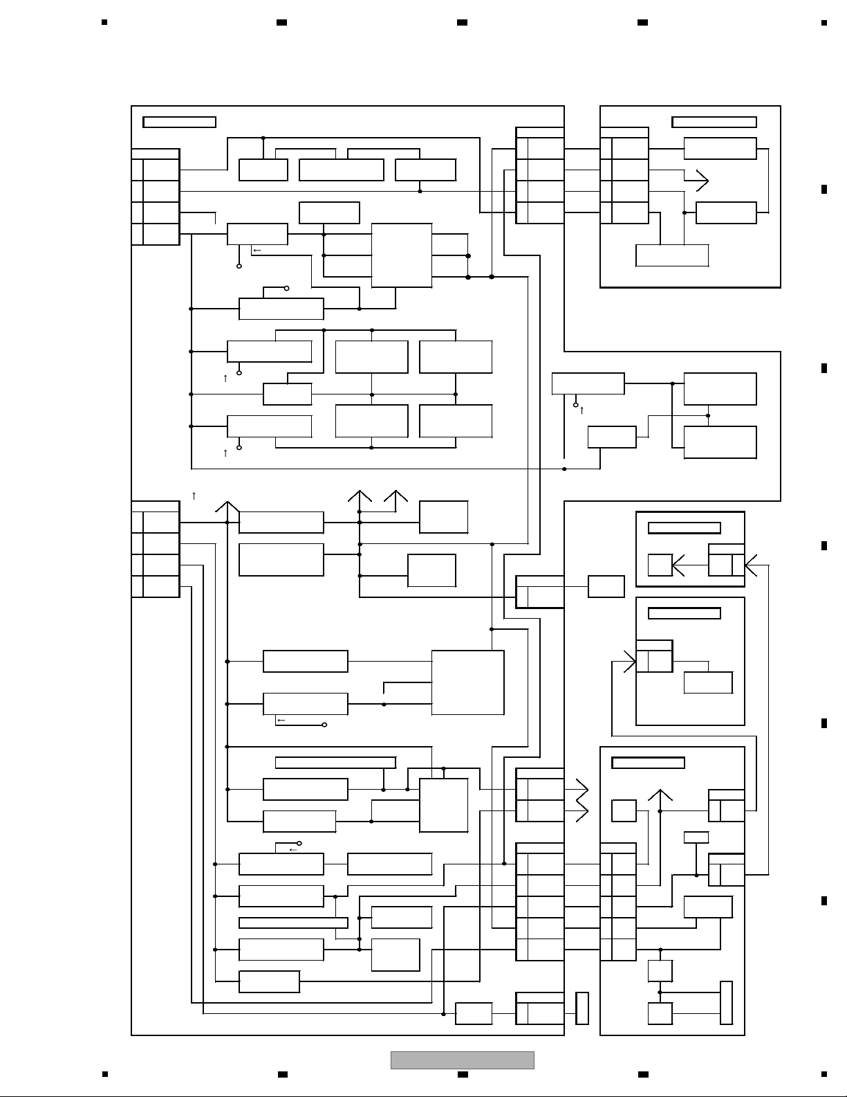
VWV2360
G
SYPS
ASSY
(VWR1415)
MAIN ASSY
(VXX3326 : BDP-05FD)
(VXX3328 : BDP-51FD)
A
1/10 -
A 10/10
A
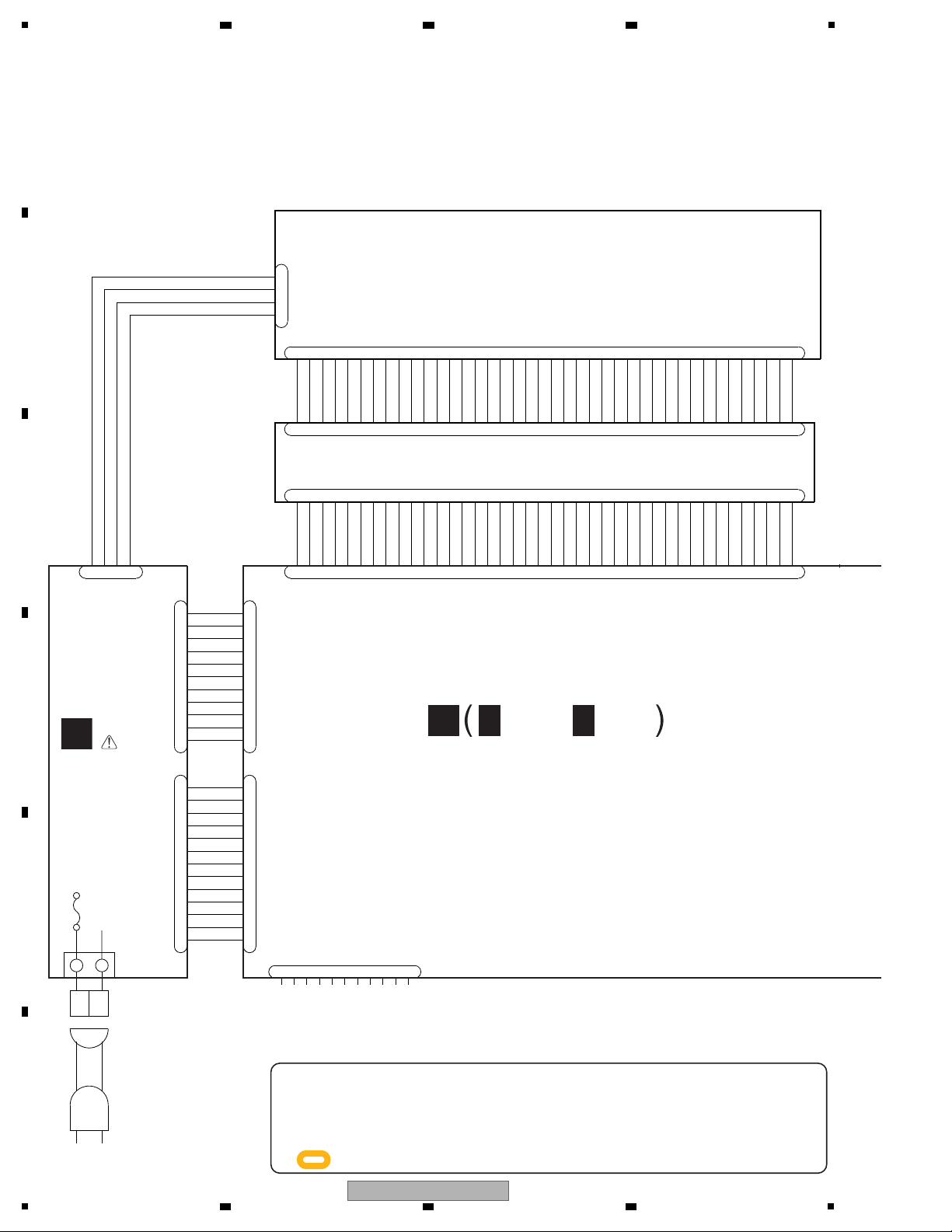
When ordering service parts, be sure to refer to "EXPLODED VIEWS and PARTS
LIST" or "PCB PARTS LIST".
The > mark found on some component parts indicates the importance of the safety
factor of the part. Therefore, when replacing, be sure to use parts of identical
designation.
: The power supply is shown with the marked box.
2 3 4
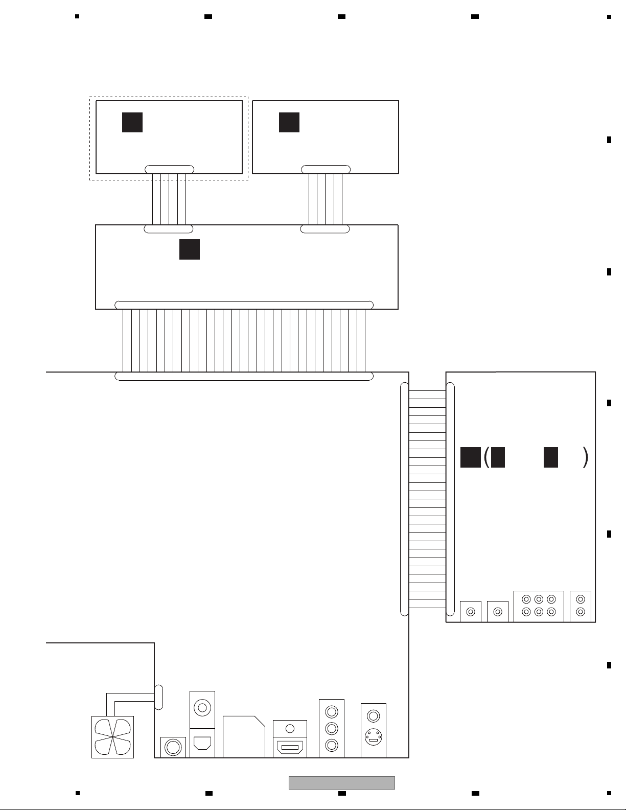
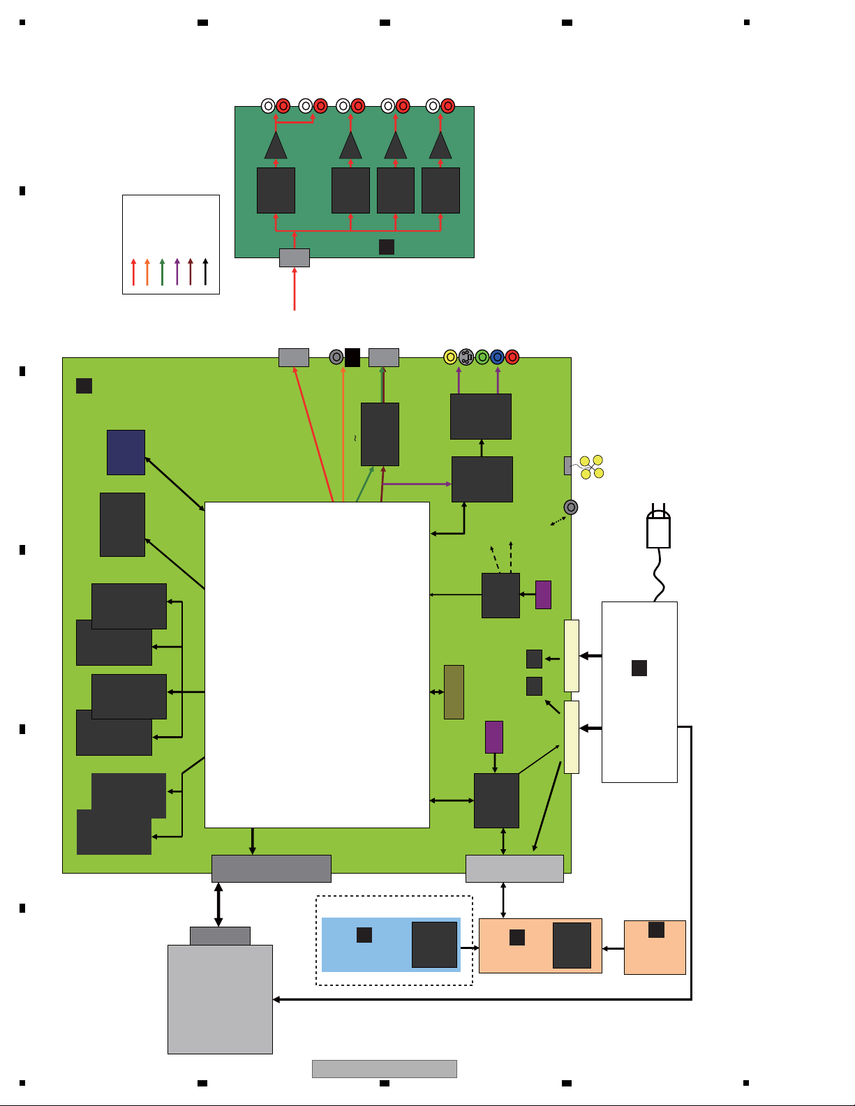
4. BLOCK DIAGRAM
4.1 OVERALL WIRING DIAGRAM
A
B
C
D
20
E
F
2 3 4
BDP-05FD
1
5
V-12A
V-12A
GNDA
V+12A
GND
GNDA
XAMUTE
V+5E
ADATA0
GND
ADATA2
GND
ADATA3
GND
ADATA1
GND
BCLK
GND
LRCK
GND
AMCLK
DAC_ML2
DAC_MDO
DAC_MC
DAC_ML
GND
V+3D
V+12A
LED_PON
GND
KEY0
V+12SW
FAN_DRIVE
GND
V+12SW
GND
GND
GND
V+5E
FLSTB
V-23SW
LED_PON
LED_FLOFF
LED_BLUE
GND
GND
V+3E
KEY0
GND
LED_HDMI
GND
GND
GND
GND
FLDATA
GND
GND
V+3D
FLCLK
IR
KEY1
GND
GND
V3EV
KEY_SENSE
GND
KEY1
GND
CN3
VKN1236-A
1
2
3
4
5
CN991
VKN1236-A
1
2
345
CN8801
AKM1273-A
1
2
VKN1617-A
CN8901
1
2
3
4
5
6
7
8
9
10
11
12
13
14
15
16
17
18
19
20
21
22
23
24
25
26
27
VKN1617-A
CN1
1
2
3
4
5
6
7
8
9
10
11
12
13
14
15
16
17
18
19
20
21
22
23
24
25
26
27
VKN1620-A
CN4401
12345
6
789
10
11
121314
15
1617181920
21
22
23
24
25
26
27
28
29
30
VKN1290-A
CN1
1
23456
789
10
111213
14
15
16
17
1819202122
23
24
2526272829
30
CN2
VKN1236-A
1
2
345
CN1
VKN1374-A
1
2
345
JA4
LR
JA3
SLSRFL
FR
Lfe
Center
7.1ch
optical
Co-Axial
2ch
AUDIO OUT
JA4351
JA8001
DIGITAL AUDIO OUT
JA6002
JA6001
JA5001
Y
Pb
Pr
COMPOSITE
S-VIDEO
VIDEO OUT
COMPONENT
SR
HDMI OUT
FAN MOTOR
AKP7220
AKB7159VKB1198
VKX1023
RKN1004
VKB1129 VKB1138
VXM1122
VDA2185-A
VDA2186-A
SBL
SBR
JA1JA2
VKB1160 VKB1130
(VWG2615)
(VWG2632)
(VWG2615)
VKB1265
(VWG2632)
VKB1159 VKB1159
(VWG2615)
(VWG2632)(VWG2632)
(VWG2615)
VKB1160
AKB7145
(VWV2375)
VKB1165
(VWV2375)
VKX1024
(VWV2375)
BDP-05FD Only
SD CARD
DKP3748
JA3701
VDA2186-A
VDA2183-A
LED_HD/DOOR_OPEN
C
PSWB ASSY
(VWG2613)
F
CAPK ASSY
(VWG2614)
B
FLKY ASSY
(VWG2612 : BDP-05FD)
(VWG2625 : BDP-51FD)
AUJB ASSY
(VWG2615 : BDP-05FD)
(VWG2632 : BDP-51FD)
D
1/2 -
D 2/2
D
6 7 8
A
B
C
D
E
5
6 7 8
BDP-05FD
F
21
1
CN
1501
PATA
IC2101
DDR2 - 0
EDE5108AJ
BG
512Mb
IC2201
DDR2 - 0
EDE5108AJ
BG
512Mb
IC2301
DDR2 - 0
EDE5108AJ
BG
512Mb
IC2401
DDR2 - 0
EDE5108AJ
BG
512Mb
IC3501
NOR FLASH
S29GL512P11TFI020
512Mb
IC3101
DDR2 - 1
EDE5116AJ
BG
512Mb
IC3202
DDR2 - 1
EDE5116AJ
BG
512Mb
JA8001
Digital Audio output
IC5001
HDMI
IC
SII9134CTU
JA5001
HDMI out put
JA6001
Composite/ S
Video out
JA6002
Component
Video out
CN8901
AUDIO
to BOARD
BD
DRIVE
CN
4401
I2C
Regul at or
AUJB ASSY
JA8401
Lsb,Rsb
JA8301
C,LFE
JA8101
Lch,Rch
JA8201
Ls,Rs
IC8101
audio DAC
WM8740
IC8201
audio DAC
WM8740
IC8401
audio DAC
WM8740
IC8301
audio DAC
WM8740
JA8102
FL,FR
SPDIF
AMCLK, ABCLK, ALRCK
ADATA0 ,ADATA1
ADATA2, ADATA3
SPDIF,SHGPIO0
5
Audio
Out
32b
32b
JA3701
SD card
connect or
SH BUS
SYPS
ASSY
CN7002CN7001
CN1301
SH+M32 JTAG
for ICE
VMCLK
27MHz
AMCLK1
36MHz
AMCLK2
33MHz
AMCLK for DAC
33/36MHz
JA4351
SR
SR
PSWB
ASSY
CAPK ASSY
FLKY ASSY
IC2
FL Dr iver
PDC182A
IC1
Touch key
CY8C20434-
12LKXI
ATAB
CN8801
FAN
IC4001
Sub
microc omputer
PDC178A8
IC1001
MAIN LSI
R8A34019BG
IC3801
PLL
PDJ015A
A
MCLK for HDMI
33/36MHz
I2C
27MHz
X'tal
12MHz
CERALOCK
PXDATA
PXDATA, SDPXDATA
VIDEO
Y,C,
Yp.Cb,Cr OUT
Analog Audio
Digit al Audio
HDMI Aud io
Analog Video
HDMI Video
Others
IC6001
Video AMP
NJM2566A
IC6301
Video ENC
ADV7340
G
BD DRIVE
A
B
F
C
D
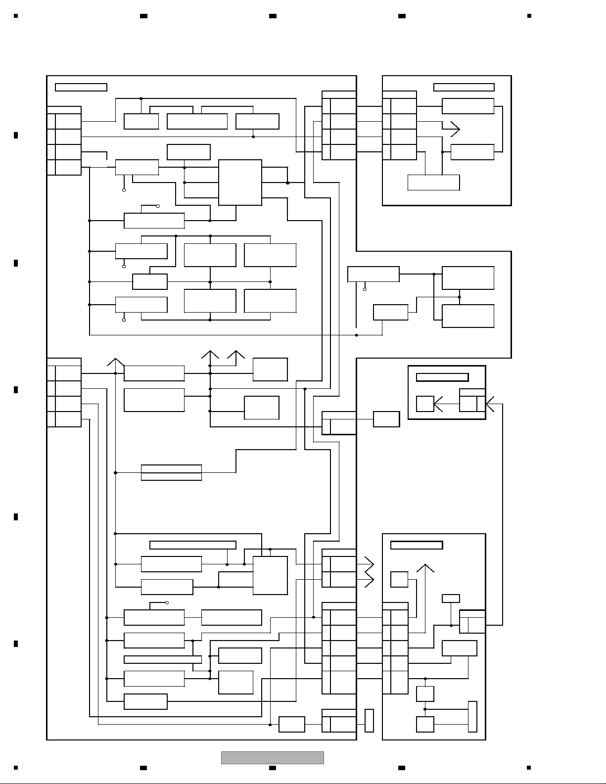
MAIN ASSY
BDP-05FD and
BDP-51FD
BDP-05FD Only
4.2 BLOCK DIAGRAM
A
2 3 4
B
C
D
E
F
22
1
BDP-05FD
2 3 4
5
MA I N to AUJB from MAIN AU JB
CN8901 CN001
from SYPS 27 V+3D V+3D 1 V+3D V+3D IC6, IC7, IC14, IC15
CN7001
VDD3R3
AUDIO DAC
13 SW-12A
V-12ASW
TR:Q8181 AUDIO Digital:IC8101 TR:Q8171 8V+5E V+5E 20 V+5E V+5E
MUTE
11 SW+12A
V+12ASW
5 V+12A
V+12A
23 V+12A
V+12A
424
7 SW+1.5V
V+1R5SW
RESET:IC4201 2 V-12A
V-12A
26 V-12A
V-12A
5VREG:IC005
6 127
3 SW+2.5V
V+2R5SW
1.1VREG:IC7101
V+1R1D
V+1R1S IC1001 V+3S V+12 VCC5
2 SKY V-12
BIAS
ON/OFF
V+1R1PLL V+3PLL IC8~13, IC16~21
LPF
V+5SW V+1R1VS V+3VS
ON/OFF V+3D
V+2R5SW
1.8VREG:IC7201
V+1R8D
V+1R8S
V+1R8ch0-1
V+1R8CH0
V+2R5SW
1.8VREG:IC2151 DDR2 ch0:IC2101 DDR2 ch0:IC2201
ON/OFF
DDR_PSW
1.8VREG:IC3151 V+1R8ch1-1 DDR2 ch1:IC3101
V+2R5SW
IC2601 VTT-ch0 V+1R8CH1
ON/OFF
DDR2 ch0:IC2301 DDR2 ch0:IC2401
DDR_PSW
V+2R5SW
1.8VREG:IC2351
VTT-CH1
IC3301 DDR2 ch1:IC3201
ON/OFF
V+1R8ch0-2
DDR_PSW
V+1R8ch1-2
V+2R5SW
to IC7201 ON/OFF to DDR_PSW
from SYPS
to IC7101_6pin(BIAS)
CN7002 CLK GEN
10 SW+5VV+5SW 3.3V REG:IC7301 V+3D IC3801
9 V+3CG PWS B
7EV+6VV+6E from FLKY
FLASH MEMORY V+3FM CN91
4 SW+12VV+12SW IC3501
CLK BUFFER
SD card
LED V+12 V+12 5 V+12
V+3SPDIF IC8001
connetcor
2 SW-23V JA3701 SD
V+3SD 4 Card
V-23SW
CAPK
from FLKY
V+3DAD
CN1
V+5SW 3.3V REG:IC7311
V+3VA V+3AAD
VIDEO 1 V3EV
V3EV
DAC
V+1R8DAD
IC 1
SENCE IC
V+5SW 1.8V REG:IC7331 V+1R8VD
V+1R8DPD
IC6301
ON/OFF
V+3D
V+3E
V+5SW
CLK BUFFER:IC5401
HDMI
FLKY
V+3ICS
V+3HDMI
JA5001
V+5SW 3.3V REG:IC5311 H D M I 21 DUMMY2 (KEY0), (KEY1) to CAPK
V+3H
CN2
V+1R8HDMI
IC5001 18 +5V IC 1 1 V3E
V+5SW 1.8V REG:IC5301 IR
V+1R8H
V+1R8LHA
to FLKB from MAIN
LED
ON/OFF
V+5SW
CN4401 CN1 to PWSB
V+6E 5V REG:IC7421 V+5VVIDEO AMP:IC6001 28V+5E V+5E 3 V5EV CN3
V5EV
1 V+12
17 V+3E V+3E 14 V3EV
V3EV
V+6E 5V REG:IC7501 V+5E
13 V+12SW V+12SW 18V+12 V+12 IC 2
RESET:IC4002 FL DRIVER
SR IN:IC4351 11 V+3D V+3D 20 SW3 SW3R3
R3
V+6E 3.3V REG:IC4101 V+3E SUB-COM 1 V-23SW V-23SW 30 V-23 V-23V
IC4001 V
TR
V+6E 5V REG:IC5321 V+5HD Q1
FAN
FLDC-(-22V)
V-23SW CN8801 F
F-
F
V+12SW Q
8801 1 V+12SW A T R
F+
L
N Q 2 FLDC+(-18V)
BDP-05FD POWER BLOCK DIAGRAM
4.3 POWER BLOCK DIAGRAM
6 7 8
A
5
6 7 8
BDP-05FD
B
C
D
E
F
23
1
BDP-51FD POWER BLOCK DIAGRAM
A
MA I N to AUJB from MAIN AUJ B
from SYPS 27 V+3D
CN7001
13 SW-12A
11 SW+12A
7 SW+1.5V
6 127
3 SW+2.5V
2 SKY V-12
B
C
CN7002 CLK GEN
10 SW+5VV+5SW
9 V+3CG PWS B
7EV+6VV+6E from FLKY
4 SW+12VV+12SW IC3501
2 SW-23V JA3701 SD
from SYPS
V-23SW
V-12ASW
V+12ASW
V+1R5SW
V+2R5SW
BIAS
V+2R5SW
V+2R5SW
ON/OFF
V+2R5SW
V+2R5SW
/OFF
ON
to IC7101_6pin(BIAS)
TR: Q8181 AUDIO Digital: IC8101 TR:Q8171
RESET:IC4201
1.1vREG:IC7101
V+5SW V+1R1VS V+3VS
ON/OFF
1.8vREG : IC7201
1.8vREG:IC2151 DDR2 ch0:IC2101 DDR2 ch0:IC2201
DDR_PSW 1.8vREG:IC3151
1.8vREG:IC2351
DDR_PSW
3.3v REG : IC7301
FLASH MEMORY V+3FM CN91
V+1R1D
ON/OFF
V+3D
V+1R8CH0
IC2601 VTT-ch0 V+1R8CH1
V+1R8ch0-2
V+1R1PLL V+3PLL
V
+1R8D
V+1R8ch0-1
DDR2 ch0 : IC2301 DDR2 ch0 : IC2401 DDR_PSW
to IC7201 ON/OFF to DDR_PSW
V+3D IC3801
2 3 4
CN8901 CN001
8V+5E V+5E 20 V+5E V+5E
5 V+12A
424
2 V-12A
V+1R1S IC1001 V+3S V+12 VCC5
V+1R8S
V+2R5SW
V+3SPDIF IC8001
V+3SD 4 Card
CLK BUFFER
SD card
connetcor
+3D
V
V+12A
V-12A
ON/OFF
IC3301
1 V+3D
23 V+12A
26 V-12A
-CH1
VTT
IC6, IC7, IC14, IC15
+3D
V
AUDIO DAC
VDD3R3
V+12A
V-12A
IC8~13,
LPF
V+1R8ch1-1
V+1R8ch1-2
LED V+12 V+12 5 V+12
MUTE
5vREG:IC005
IC16~21
DDR2 ch1:IC3101
DDR2 ch1:IC3201
D
V+5SW
3.3v REG : IC7311
V+5SW
CLK BUFFER: IC5401
V+5SW
3.3v REG: IC5311
E
F
V-23SW CN8801 F
V+5SW
1.8v REG: IC5301
ON/OFF
V+6E
5v REG: IC7421
V+6E
5v REG: IC7501
SR IN: IC4351
V+6E
3.3v REG: IC4101
V+6E
5V REG: IC5321
V+12SW Q8801 1 V+12SW A T R
V+5SW
V+5HD Q1
V+3VA
V+3ICS
V+3H
V+1R8HDMI
V+1R8H
V+1R8LHA
V+5V
VIDEO AMP:IC6001
V+5E
RESET : IC4002
V+3E SUB-COM 1 V-23SW V-23SW 30 V-23 V-23V
IC4001 V
V+3HDMI
HDMI 21
IC5001 18 +5V IC 1
HDMI
JA5001
DUMMY2
to FLKB from MAIN
CN4401 CN1 to PWSB
28V+5E V+5E 3 V5EV CN3
17 V+3E V+3E
13 V+12SW V+12SW 18V+12 V+12 IC 2
11 V+3D V+3D 20 SW3 SW3R3
FAN
N Q 2 FLDC+(-18V)
IR
14 V3E
R3
FLKY
(KEY0), (KEY1)
V5EV
V3EV
V
TR
FLDC-(-22V)
LED
1 V+12
FL DRIVER
FF+
F
L
24
BDP-05FD
1
2 3 4

5
5. DIAGNOSIS
5.1 POWER ON SEQUENCE
6 7 8
Power On Sequence
Pressing of the POWER key is detected by the IC4001 Submicrocomputer on the MAIN Assy.
The IC4001 then outputs a POWER_ON signal to the SYPS Assy.
After receiving the POWER_ON signal, the SYPS Assy activates, secondary
Power[SW+12 V], setting it to ON.
The R8A34019BG (IC1001), the core LSI, starts up. {RS-232C connectorCN1601,
log it to ON}
Communication between the R8A34019BG and the DDR2 SDRAM starts.
Communication between the R8A34019BG and the FLASH_IC starts.
A
B
C
It takes about 1 minute to complete the startup process.
Troubleshooting
Are the pins at CN7001 and CN7002 supplied with voltages?
MAIN ASSY(1/8) V+3S, V+3PLL with 3.3 voltages?
MAIN ASSY(1/8) V+1R8S with 1.8 voltages?
MAIN ASSY(1/8) V+1R1S with 1.1 voltages?
Is the reset signal H? (R1161)
Is the 27 MHz CLK oscillating? (R1141)
Power ON, and log of R8A34019BG stops with [DRAM failed].
R8A34019BG and communication failure of DDR memory.
Power ON, and log of R8A34019BG stops with [zboot failed].
R8A34019BG and communication failure of FLASH memory.
D
E
F
BDP-05FD
5
6 7 8
25
1
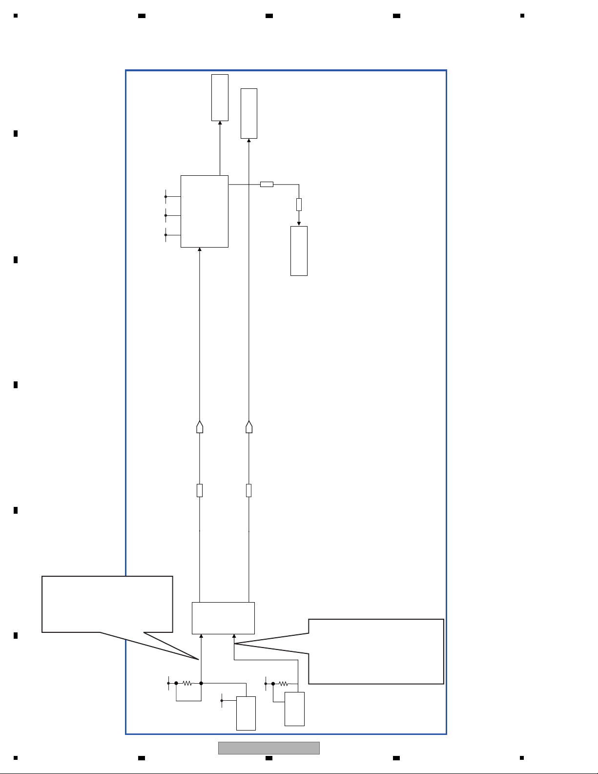
5.2 RESET ON SEQUENCE
A
B
3.3V 1.1V 1.8V
2 3 4
Drive
NOR FLASH
ATIRESET
Main_LSI
R8A34019BG
R1133
HDMI_RESET
R5034
HDMI
SiI9134
C
0 Ω
NOR FLASH
RESET2#
0 Ω
MAIN LSI
D
E
RESET_SKY#
[detect 1.1 V Reset]
After detecting 1.1 V ON/OFF,
Transit ResetG "L", then instantly
to ResetG "H".
IC4001
Subcon
SCON_XRESET
After detecting 3.3 V(E) ON/OFF,
hold 200ms SCON_XRESET "L"
and turn to SCON_XRESET "H".
By main reset release "H", Subcon
10k
3.3V
F
1.1V
1.1V
ResetIC
IC4201
3.3V(E)
22k
3.3V
IC4002
conducts operation.
ResetIC
26
BDP-05FD
1
2 3 4
5
6 7 8
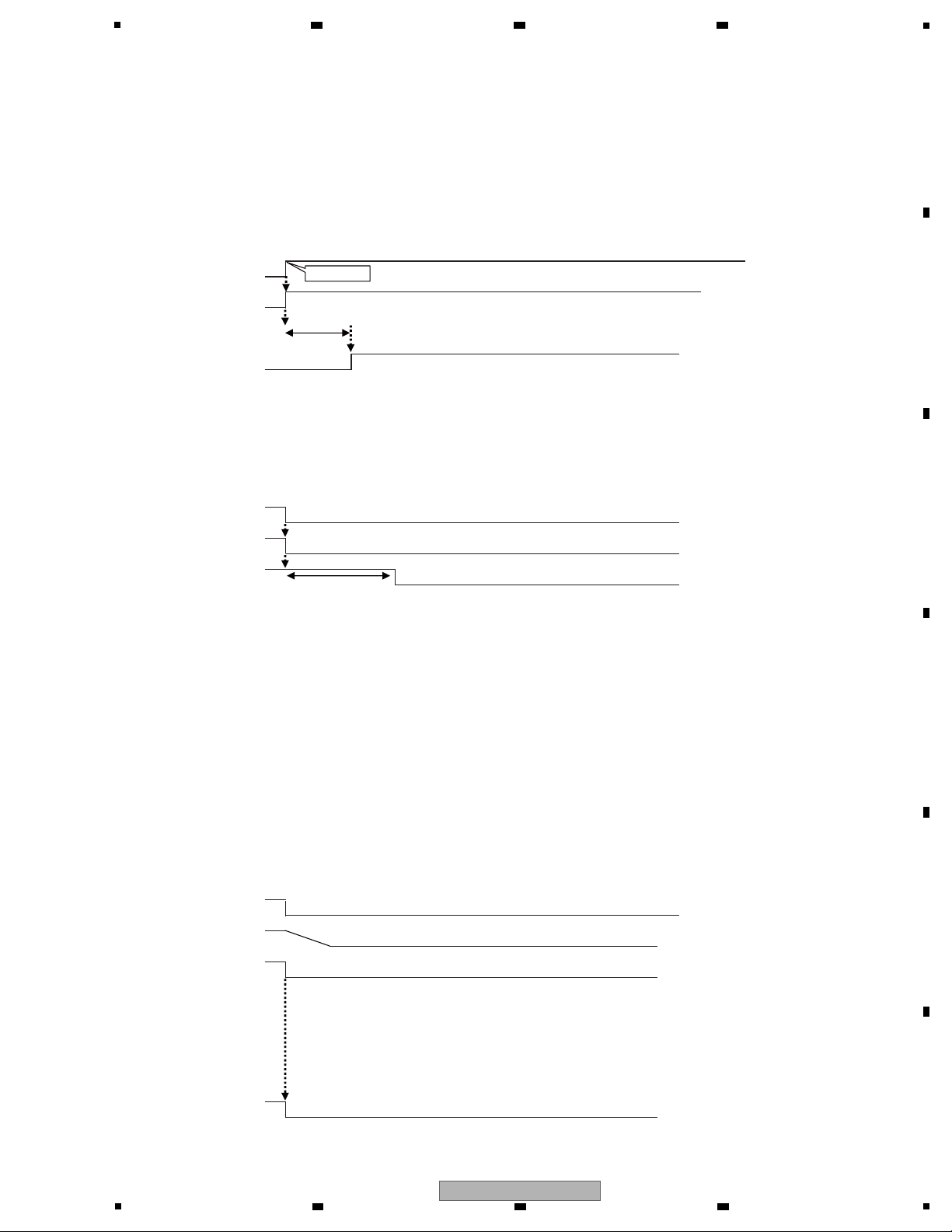
1.Reset specification
[On start-up]
Receiving Power ON key, sub-microcomputer turns Power_ON signal to ”H”.
Receiving Power ON signal, power turns each SW power to ”ON”.
1.1 V turns ON.
Sub-microcomputer is (after 200ms) to Reset_SKY#, Reset 2#, Reset 3# ”L” turn to ”H”.
Power_ON
I N
Reset_SKY#,2#,3#
[At normal end]
Sub-microcomputer detects the pushing of Power key, then notifies PowerOFF to R8A34019BG by I C.
Receiving PowerOFF notification, R8A34019BG conducts end processing.
R8A34019BG instructs PowerOFF to sub-microcomputer by I C.
Sub-microcomputer turns Reset_SKY#, Reset 2#,Reset 3#,to ”L”, and after 200msec, PowerON signal to ”L”.
After 50msec, power turns each SW power to OFF.
Reset_SKY#,2#,3#
PON key
200ms
2
2
A
B
C
Power_ON
200ms
[Power abnormality]
*Reset operation in the case of 1.1 V drop.
Determine if ResetG becomes ”L”, then turn Reset# - Reset3# to “L”.
[At abnormal end]
ACOFF
By turning V+1R1D to OFF, ResetG# turns to ”L” by ResetIC.
Power_ON
V+1R1D
Reset
(IC4201 OUT)
D
E
Reset_SKY#,
Reset 2#,
Reset 3#
F
BDP-05FD
5
6 7 8
27
1
6. SERVICE MODE
6.1 OSD
2 3 4
A
B
C
D
E
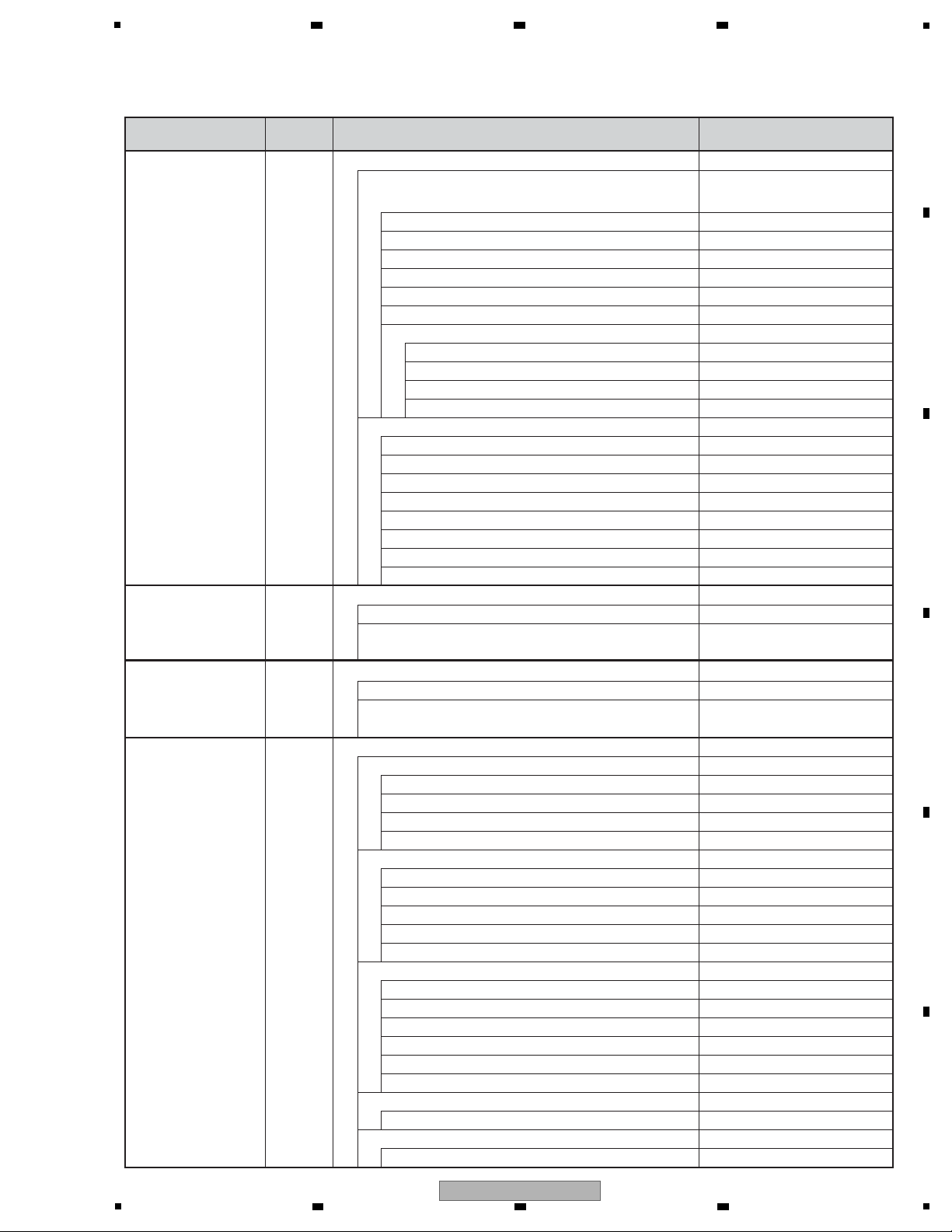
Indication items for the OSDs for debugging
Remote Control
Unit Command
[ESC]+[DISP] 1st screen Service Indication (software information)
[ESC]+[SIDE-B] 1st screen
[ESC]+[DISP]+[2] 1st screen
[ESC]+[DISP]+[3] 1st screen ATA/ATAPI DEBUG OSD-Command history (ALL)
[ESC]+[DISP]+[4] Results of self-diagnosis
Screen Indication Items for the OSDs Remarks
Product serial No./destination
Model No.
Released version No.
Revision No.
Submicrocomputer version data
Drive model No.
Drive version No.
Drive serial No.
DVD-Video region No.
BD-ROM region No.
CPRM ID
MAC address
2nd screen OSD Filter
Setup value of the OSD FILTER
Specifications 1 for error rate measurement (with OK/NG judgment)
Results of error rate measurement OK/NG
Specifications 2 for error rate measurement (for continuous playback)
Title/Chapter data
Playback duration data
LgcSct address data
Error rate data (error rate value)
Packet command from the host
Error data from the status register
2nd screen ATA/ATAPI DEBUG OSD-Command history (ERROR)
Packet command that has been failed
Error Code
Command-specific information
3rd screen ATA/ATAPI DEBUG OSD-Drive maintenance data
Power ON/accumulated power-on duration
LD read power-on duration for the BD
LD read power-on duration for the DVD
Serial No. of the PU
4th screen ATA/ATAPI DEBUG OSD-Judgment of LD degradation
Judgment of degradation of the LD for the BD (OK/NG)
Judgment of degradation of the LD for the DVD (OK/NG)
Judgment of degradation of the LD for the CD (OK/NG)
Temperature inside the writer
Version/Revision Nos. of the SKY chip
HDMI transmitter IC check
Communication check of the submicrocomputer
PLL synthesizer check
DRIVE check
The data must be displayed on
the subpage of the software
information screen.
To see the result, press ESC then SIDE-B.
F
28
1
2 3 4
BDP-05FD
5
6 7 8
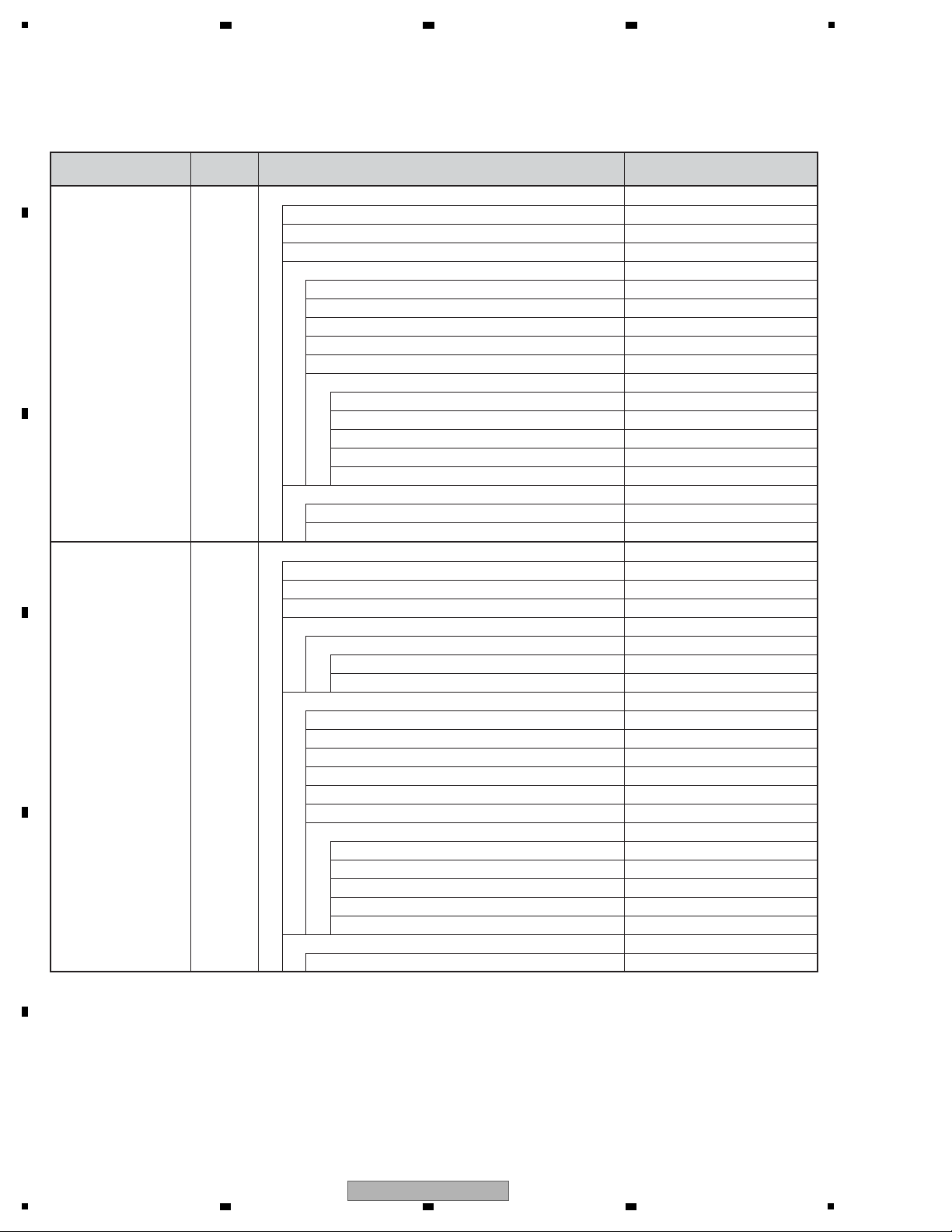
Remote Control
Unit Command
Screen Indication Items for the OSDs Remarks
[ESC]+[DISP]+[5] AV output data
Video data
Video encoder data
Component output resolution
HDMI output resolution
Frame rate
Content resolution
Content aspect ratio
Data on VBID and WSS
CGMS-A/Copyright
APS
MacroVision
Aspect
Audio data
Sampling frequency
Category code (Number of Bits & definition)
Word Length
C/L bit: Indications on number of bits & status (Free/Once/Disable)
Audio muting status
LPCM/BitStream output
Number of output channels
HDMI ACP Type
[ESC]+[DISP]+[6] HDMI data
[ESC]+[DISP]+[7] Connection status
* No data because screen specifications are to be designed by
engineers for the HDMI modules.
[ESC]+[DISP]+[8] User Interface data
Logs for received keys
* No data because screen specifications are to be designed by
engineers for the UI modules.
[ESC]+[DISP]+[9] Contents data
BD-ROM
HDMV
BD-J
Authoring maker
Total number of titles
BD-R/RE
BDMV
BDAV
AVC HD
Authoring maker
Total number of titles
DVD
BDMV
AVC HD
DVD-Video
DVD VR
Authoring maker
Total number of titles
CD
Total number of titles
PC-FILES
Total number of files
A
*These data are to be used merely as
a guide, as they were designed to be
used for product development.
B
C
* Two screens are to be used for HDMI data.
D
E
F
BDP-05FD
5
6 7 8
29
1
A
2 3 4
Remote Control
Unit Command
Screen Indication Items for the OSDs Remarks
[ESC]+[DISP]+[10] Playback data (BD-ROM)
Title No.
Chapter No.
Elapsed time within a title
Video data
B
Audio data
C
[ESC]+[DISP]+[11] Playback data (BD-R/RE)
Title No.
Chapter No.
Elapsed time within a title
Navigation data
D
E
Video data
Audio data
Primary Video Stream
Secondary Video Stream
Resolution
Source video aspect ratio
Frame rate
AACS data
CPI
CCI
APS
ICT
DOT
Primary Audio Stream
Secondary Audio Stream
Playback stream format
SESF
ISDB
Video stream data
Playlist data (Virtual/Real-PlayList)
Playlist No.
Resolution
Source video aspect ratio
Frame rate
AACS data
CPI
CCI
APS
ICT
DOT
Audio Stream data
F
30
1
2 3 4
BDP-05FD
 Loading...