

Page 1

Operation Manual
AUDIO MASTER UNIT
AXM-P90RS
English
Page 2
Contents
Thank you for buying this Pioneer product.
Please read through these operating instructions so you will know how to operate
your model properly. After you have finished reading the instructions, keep this man-
ual in a safe place for future reference.
Before You Start
About this unit 3
Visit our website 3
In case of trouble 4
Use and care of the remote control 4
Resetting the microprocessor 5
What’s What
Display unit 6
Card remote control 6
Steering remote control 7
Basic Operations
Turning the unit on 8
Selecting a source 8
Adjusting the volume 8
Turning the unit off 8
Initial Settings
Adjusting initial settings 9
Setting the clock 9
Setting the display appearance 10
Configure the general settings 11
Setting the menu lock 11
Setting the audio processor 11
Available accessories
Playing songs on iPod 13
Multi-CD Player 15
DVD Player 18
TV tuner 21
Auxiliary (AUX) devices 22
Connections
Connecting the power cable 27
Connecting the audio processor 28
Connecting the Pioneer IP-BUS devices 29
Connecting the AUX devices 30
Selecting the input setting switch 31
Using the speaker-RCA conversion cable 31
Installation
Installing the hide-away unit 32
Installing the display unit 33
Installing the steering remote control 37
Additional Information
Troubleshooting 39
Specifications 40
Audio unit control
Controlling the audio processor 24
Differentia of the audio function 24
Other Functions
Other Functions 25
2
En
Page 3
Before You Start
If you want to dispose this product, do not mix
it with general household waste. There is a separate collection system for used electronic
products in accordance with legislation that requires proper treatment, recovery and recycling.
Private households in the member states of
the EU, in Switzerland and Norway may return
their used electronic products free of charge
to designated collection facilities or to a retailer (if you purchase a similar new one).
For countries not mentioned above, please
contact your local authorities for the correct
method of disposal.
By doing so you will ensure that your disposed
product undergoes the necessary treatment,
recovery and recycling and thus prevent potential negative effects on the environment
and human health.
About this unit
This unit is designed to control the Pioneer
Audio Processor (e.g. RS-A9 or DEQ-P90).
Using this unit converts the sound from your
car audio into the high quality sound of the
Pioneer audio processor without combining
the Pioneer ODR series CD Player or Pioneer
Reference series CD Player.
Also, the supplied remote control can control
the separately sold Pioneer DVD player (e.g.
XDV-P6), Pioneer Multi-CD player, Pioneer
iPod adaptor (e.g. CD-IB100B) and Pioneer TV
tuner.
! This unit can control five devices as AUX
sources. The following devices can be connected to this unit.
Section
01
Before You Start
— Devices with RCA output; This unit con-
trols them as AUX1 Main or
AUX2 AUX.
— Devices with digital output; This unit
controls it as AUX3 Digital.
— Devices with 3.5 mm mini plug; This
unit controls it as AUX4 MiniPlug.
— Devices with Pioneer IP-BUS; This unit
controls it as AUX5 IP-BUS.
! If the equipment you want to connect as an
AUX unit does not have an RCA output, the
supplied speaker-RCA conversion cable
can be used. For details, refer to Using the
speaker-RCA conversion cable on page 31.
CAUTION
! Do not allow this unit to come into contact
with liquids. Electrical shock could result.
Also, damage to this unit, smoke, and overheating could result from contact with liquids.
! Keep this manual handy as a reference for op-
erating procedures and precautions.
! Always keep the volume low enough so that
you can hear sounds from outside the vehicle.
! Protect this unit from moisture.
! If the battery is disconnected or discharged,
the preset memory will be erased and must be
reprogrammed.
Visit our website
Visit us at the following site:
! Register your product. We will keep the de-
tails of your purchase on file to help you
refer to this information in the event of an
insurance claim such as loss or theft.
! We offer the latest information about
Pioneer Corporation on our website.
En
3
Page 4
Section
01
Before You Start
In case of trouble
Should this product fail to operate properly,
contact your dealer or nearest authorized
Pioneer Service Station.
Use and care of the remote
control
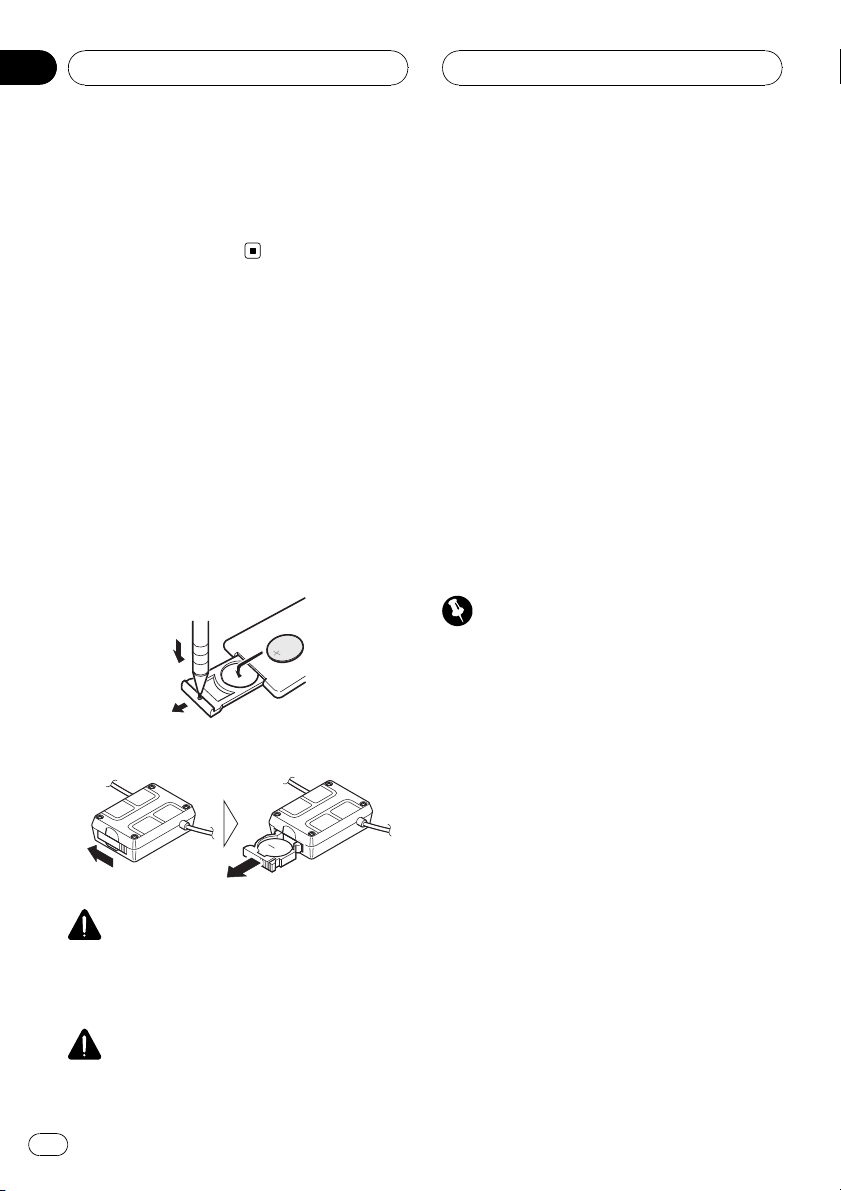
Installing the battery
Slide the tray on the back of the remote control out and insert the battery with the plus (+)
and minus (–) poles pointing in the proper direction.
! When using for the first time, pull out the
film protruding from the tray.
Card remote control
Steering remote control
WARNING
Keep the battery out of the reach of children.
Should the battery be swallowed, consult a doctor immediately.
CAUTION
! Use one CR2025 (3 V) lithium battery.
! Remove the battery if the remote control is not
used for a month or longer.
! There is a danger of explosion if the battery is
incorrectly replaced. Replace only with the
same or equivalent type.
! Do not handle the battery with metallic tools.
! Do not store the battery with metallic objects.
! In the event of battery leakage, wipe the re-
mote control completely clean and install a
new battery.
! When disposing of used batteries, please
comply with governmental regulations or environmental public institutions’ rules that
apply in your country/area.
! Always check carefully that you are loading
the battery with its plus (+) and minus (–)
poles facing the proper directions.
Using the remote control
Important
! Do not store the remote control in high tem-
peratures or direct sunlight.
! Do not let the remote control fall onto the
floor, where it may become jammed under the
brake or accelerator pedal.
! If any of the following problems occur, imme-
diately stop using the unit and consult the
dealer from whom you purchased it.
— Smoke is coming from the unit.
— Abnormal odor is coming from the unit.
— A foreign object has entered the unit.
— Liquid has been spilled on or into the unit.
If you continue to use this unit without finding
a remedy, the unit may be damaged badly, resulting in a serious accident or fire.
! Do not disassemble or modify this unit. To do
so may cause a malfunction.
! Do not operate this unit while manipulating
the steering wheel as it might result in a traffic
accident.
4
En
Page 5
4
8
Before You Start
Section
01
Before You Start
! If you need to operate this unit while driving,
look ahead carefully to avoid being involved in
a traffic accident.
! Do not leave this steering remote control free
(unattached). When stopping the car or turning, the unit might drop on the floor. If the unit
rolls under the brake pedal, it might prevent
the driver from braking properly, causing serious problems. Be sure to fix the steering remote control to the steering wheel.
Card remote control
! Point the remote control in the direction of
the remote control sensor to operate.
! The remote control may not function prop-
erly in direct sunlight.
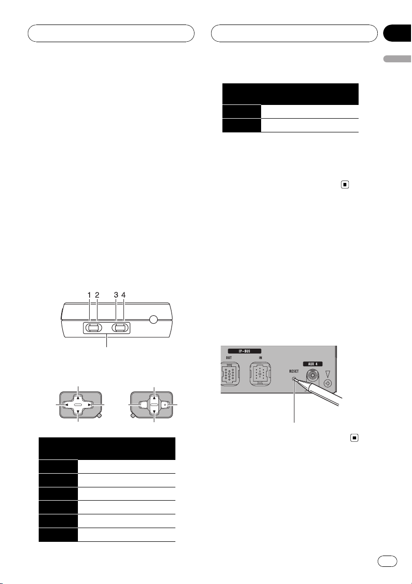
Steering remote control
! Key assignment can be changed by select-
ing the DIP switch.
DIP switch
! Key assignment conversion chart
2
6
DIP
switch
7 SOURCE SOURCE
8 VOLUME (+) VOLUME (–)
1-3
1-4
2-3
2-4
! If DIP switch is selected to 1-3 or 2-3, the
steering remote control controls this unit.
! If DIP switch is selected to 1-4 or 2-4, this
steering remote control can be used as a
general purpose for Pioneer unit.
Resetting the microprocessor
The microprocessor must be reset under the
following conditions:
! Prior to using this unit for the first time
after installation
! If the unit fails to operate properly
! When strange or incorrect messages ap-
pear on the display
% Press RESET with a pen tip or other
pointed instrument.
1
DIP
switch
1 cd
2 ba
3 da
4 ab
5 ATT ATT
6 VOLUME (–) VOLUME (+)
1-3
1-4
5
3
2-3
2-4
7
RESET button
5
En
Page 6
21
1
234
5
6
7
8
9
a
b
c
d
e
f
Section
02
What’s What
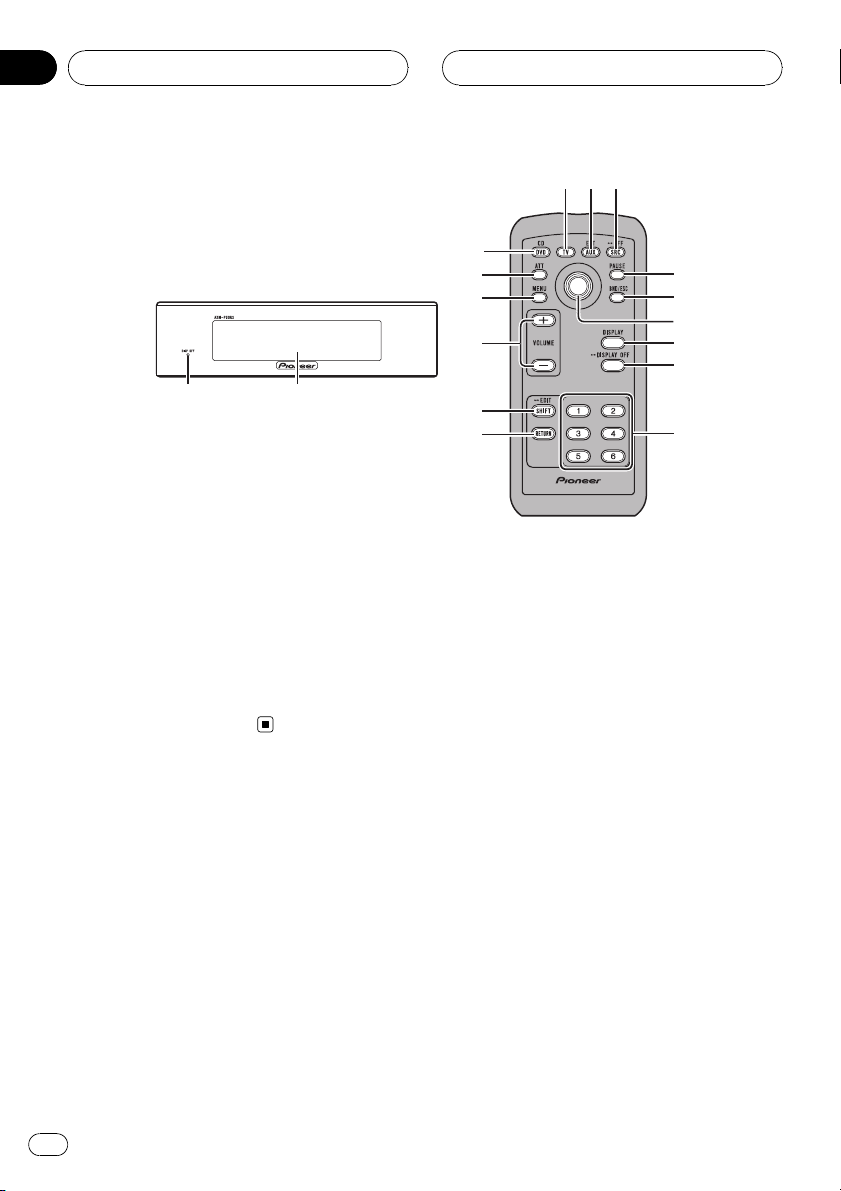
Display unit
1 Display off indicator
Lights up when the display indication is
turned off.
2 Information display
Display information for each connectedsource and its settings.
Card remote control
1 CD/DVD button
Press to select a iPod (iPod), Multi CD (CD
player) or DVD (DVD player) source .
2 TV button
Press to select a TV (TV) source.
3 AUX/EXT button
Press to select an AUX (AUX) or External
(external) source.
4 SOURCE button
Press to cycle through all the available
sources. Press and hold to turn the source
off.
5 PAUSE button
Press to turn pause on or off.
6 BAND button
Press to select among two TV bands and to
cancel the control mode of functions.
7 Thumb pad
Move to perform manual seek tuning, fast
forward, reverse and track search controls.
Also used for controlling functions.
Click and hold to change between normal
playback display and menu setting display.
! Clicking and holding thumb pad corre-
sponds to the opening or closing operation of the remote control cover
described in the audio processor’s manual. For details, refer to audio processor ’s
owner’s manual.
6
En
Page 7

g df 4
What’s What
Section
02
8 DISPLAY button
Press to display different information on the
selected channel. Press and hold to switch
the scroll setting.
9 DISPLAY OFF button
Press and hold to turn the display indication
off or on to reduce noise.
a FUNC 1 to FUNC 6 buttons
Press to select and control functions.
b RETURN button
Press to change to the menu setting display
from the detail setting display.
c SHIFT button
Press to change to the detail setting display
from the menu setting display.
d VOLUME buttons
Press to increase or decrease the volume.
Steering remote control
g a/b/c/d buttons
Press to perform manual seek tuning, fast
forward, reverse and track search controls.
Also used for controlling functions.
What’s What
e MENU button
Press to cycle through audio menus; Main
(main menu), Equalizer (equalizer menu) or
Network (network menu).
f ATT button
Press to quickly lower the volume level by
about 90%. Press once more to return to the
original volume level.
En
7
Page 8
Section
03
Basic Operations
Turning the unit on
% Press SOURCE to turn the unit on.
When you select a source, the unit is turned
on.
Selecting a source
% Press SOURCE to select a source.
Press SOURCE repeatedly to switch between
the following sources:
TV (television)—S-DVD (DVD player/multiDVD player)—Multi CD (multi-CD player)—
iPod (iPod)—External (external unit 1)—
External (external unit 2)—AUX1 Main
(AUX1)—AUX2 AUX (AUX2)—AUX3 Digital
(AUX3)—AUX4 MiniPlug (AUX4)—
AUX5 IP-BUS (AUX5)
% Press CD/DVD, TV or AUX/EXT to select
a source.
Press each button repeatedly to switch between the following sources:
! CD/DVD:
S-DVD (DVD player/multi-DVD player)—
Multi CD (multi-CD player)—iPod (iPod)—
Sources off
! TV:
Television (television)—Sources off
! AUX/EXT:
External (external unit 1)—External (exter-
nal unit 2)—AUX1 Main (AUX1)—
AUX2 AUX (AUX2)—AUX3 Digital (AUX3)
—AUX4 MiniPlug (AUX4)—AUX5 IP-BUS
(AUX5)—Source off
— When there is no magazine in the multi-
CD player.
— When there is no magazine in the multi-
DVD player.
— When there is no disc in the DVD player.
— When AUX (auxiliary input) is set to off
(refer to page 11).
! External unit refers to a Pioneer product (such
as ones available in the future) that, although
incompatible as a source, enables control of
basic functions with this unit. Two external
units can be controlled with this unit. When
two external units are connected, the allocation to external unit 1 or external unit 2 is automatically set by this unit.
Adjusting the volume
% Use VOLUME to adjust the sound level.
Press to increase or decrease the volume.
Turning the unit off
% Press SOURCE and hold until the unit
turns off.
Notes
! In the following cases, the sound source will
not change:
— When no unit corresponding to the se-
lected source is connected.
8
En
Page 9

Initial Settings
Section
04
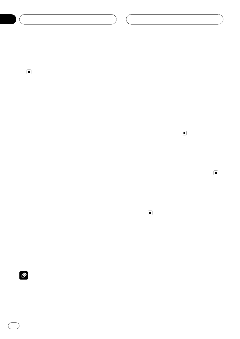
Adjusting initial settings
1
Using the initial settings, you can customize
various system settings to achieve optimal performance from this unit.
1 Initial setting screen
Shows the function names and status.
1 Press SOURCE and hold until the unit
turns off.
# Pressing CD/DVD, TV or AUX/EXT can also
turn this unit off.
2 Press SHIFT to display the initial setting
display.
Clock adjustment menu, display setting menu,
general setting menu and menu lock can be
selected from this screen.
3 Press FUNC 1 to FUNC 5 to select the desired setting.
FUNC 1: Press to switch to the clock adjust-
ment menu. (Setting the clock on this page)
FUNC 2: Press to switch to the display setting
menu. (Setting the display appearance on the
next page)
FUNC 3: Press to switch to the general setting
menu. (Configure the general settings on page
11)
FUNC 4: Press to turn the menu lock on or off.
(Setting the menu lock on page 11)
FUNC 5: Press to switch to the audio processor setting menu. (Setting the audio processor
on page 11)
Setting the clock
Use these instructions to set the clock.
Switching to clock adjustment
screen
% Press FUNC 1 on the initial setting
screen.
Clock adjustment screen is displayed and the
clock can now be set.
Setting the clock
1 Move the thumb pad to select the segment of the clock display you wish to set.
Moving the thumb pad left or right will select
one segment of the clock display:
Hour—Minute
2 Move the thumb pad to set the clock.
Moving the thumb pad up will increase the selected hour or minute. Moving the thumb pad
down will decrease the selected hour or minute.
Setting the clock by the time signal
% Press FUNC 2 on the clock adjustment
screen.
Pressing FUNC 2 will reset the minutes segment.
If 00 to 29, the minutes are rounded down.
(e.g., 10:18 becomes 10:00.)
If 30 to 59, the minutes are rounded up. (e.g.,
10:36 becomes 11:00.)
Initial Settings
4 Press BAND to exit the initial setting
display.
En
9
Page 10

Section
04
Initial Settings
Turning the off clock display on
or off
If the off clock display is turned on, the clock
appears on the display when the sources are
off.
% Press FUNC 1 on the clock adjustment
screen.
Pressing FUNC 1 repeatedly will turn the clock
display on or off.
Returning to the initial setting
screen
% Press RETURN.
Pressing RETURN takes you back to the initial
setting display.
Setting the display
appearance
Switching to display setting screen
% Press FUNC 2 on the initial setting
screen.
Switching the dimmer setting
To prevent the display from being too bright at
night, the display is automatically dimmed
when the car’s headlights are turned on. You
can turn the dimmer on or off.
% Press FUNC 1 on the display setting
screen.
Pressing FUNC 1 repeatedly will turn the dimmer on or off.
Selecting the wallpaper pattern
You can select a display wallpaper.
% Press FUNC 2 on the display setting
screen.
Pressing FUNC 2 repeatedly will switch the
display wallpaper.
Switching the reverse mode
If you do not perform an operation for about
30 seconds, screen indications start to reverse,
and continue reversing every 10 seconds.
% Press FUNC 3 on the display setting
screen.
Pressing FUNC 3 repeatedly will turn the reverse mode on or off.
Display setting screen is displayed. Display
settings can now be set.
Adjusting the brightness
You can adjust the display brightness.
% Move the thumb pad to adjust the
brightness level.
Moving the thumb pad left or right increases
or decreases the brightness level.
10
En
Returning to the initial setting
screen
% Press RETURN.
Pressing RETURN takes you back to the initial
setting display.
Page 11

Initial Settings
Section
04
Configure the general settings
Switching to general setting
screen
% Press FUNC 3 on the initial setting
screen.
General setting screen is displayed and general settings are now available.
Switching the auxiliary setting
This unit can control up to five auxiliary devices. Each auxiliary device’s setting must be
activated independently in order to connect
and use with this unit. Before using auxiliary
devices, be sure to configure this setting.
1 Press FUNC 1 on the general setting
screen.
AUX setting screen is displayed and AUX settings are now available.
2 Press the button (FUNC 1 to FUNC 5)
that has auxiliary device assigned.
Pressing the button (FUNC 1 to FUNC 5) repeatedly will turn the auxiliary device on or off
independently.
Setting the confirmation sound
The short beep that sounds when operating
this unit can be turned on or off.
! This function is effective only when the re-
mote control sensor is installed.
% Press FUNC 3 on the general setting
screen.
Pressing FUNC 3 repeatedly will turn the confirmation beep sound on or off.
Returning to the initial setting
screen
% Press RETURN.
Pressing RETURN takes you back to the initial
setting display.
Setting the menu lock
Menu lock avoids the readjusting of audio settings. If menu lock is turned on, all audio adjustment are turned off.
Setting the menu lock
% Press FUNC 4 on the initial setting
screen.
Pressing FUNC 4 repeatedly will turn the
menu lock on or off.
Initial Settings
Setting the battery voltage
indication
Shows the battery voltage.
! Voltage indicator may differ from the actual
voltage level.
% Press FUNC 2 on the general setting
screen.
Pressing FUNC 2 repeatedly will turn the battery voltage indication on or off.
Setting the audio processor
In order to use this system correctly, this unit
needs to be adapted to the connected audio
processor. Before using this system, set this
function correctly.
En
11
Page 12

Section
04
Initial Settings
Setting the audio processor
1 Press FUNC 5 on the initial setting
screen.
Audio processor setting screen is displayed
and audio processor settings are now available.
2 Press FUNC 1 to FUNC 4 to select the
connected audio processor.
! DEQ: When DEQ-P90 is connected.
! A9: When RS-A9 is connected.
! P90: When RS-P90 is connected.
! P70: When RS-P70x (
— RS-P70x (
II
) is connected.
II
) is only available in Japan.
12
En
Page 13
3
Available accessories
Section
05
Playing songs on iPod
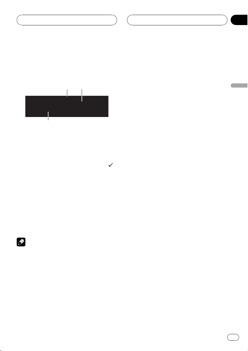
Listening to songs on your iPod
You can use this unit to control an interface
adapter for iPod, which is sold separately.
1 2
1 Song number indicator
Shows the number of the song playing.
2 Play time indicator
3 Text information
1 Press SOURCE to select the iPod.
While connected to this unit, PIONEER (or
(check mark)) is displayed on the iPod.
# Pressing CD/DVD can also select iPod.
2 To perform fast forward or reverse,
hold the thumb pad left or right.
3 To skip back or forward to another
track, move the thumb pad left or right.
Moving the thumb pad right skips to the start
of the next song. Moving it left once skips to
the start of the current song. Moving it left
again will skip to the previous song.
Notes
! If an error message is displayed, refer to the
interface adapter for iPod owner’s manual.
! When the ignition switch is set to ACC or ON,
the iPod’s battery is charged while the iPod is
connected to this unit.
! While the iPod is connected to this unit, the
iPod cannot be turned on or off.
! Before connecting the dock connector to the
iPod, disconnect the headphones.
! The iPod is turned off about two minutes after
the ignition switch is set to OFF.
Browsing for a song
Operations to control an iPod with this unit is
designed to be as close to the iPod to make
operation and song search easy.
! If the characters recorded on the iPod are
not compatible with this unit, those characters will not be displayed.
1 Move the thumb pad up or down to select a category.
Moving the thumb pad up or down selects the
category in the following order:
PLAYLIST (playlists)—ARTIST (artists)—
ALBUM (albums)—SONG (songs)—GENRE
(genres)
List for the selected category is displayed.
2 Move the thumb pad right to determine the category.
List for the selected category is displayed.
# You can start playback throughout the selected category by holding the thumb pad right.
3 Move the thumb pad up or down to select a playlist, song list, album list, artist list
or genre list from the lists.
Moving the thumb pad up or down switches
the list.
4 Move the thumb pad right to determine the list.
Lists for the selected list are displayed.
5 Repeat steps 3 and 4 to find a song you
want to listen to.
# When you selected GENRE, ARTIST, ALBUM
or SONG, you can start playback throughout the
selected list. To do this, hold the thumb pad right.
# To return to the previous group of list titles,
move the thumb pad left.
# To return to the category select display, hold
the thumb pad left.
Selecting a playlist
You can select a playlist from your iPod.
! If the characters recorded on the iPod are
not compatible with this unit, those characters will not be displayed.
Available accessories
En
13
Page 14

Section
05
Available accessories
! If playlist has been selected, first, this unit
shows playlist of your iPod’s name. This
plays all the songs in your iPod.
% Move the thumb pad up or down to select a playlist.
# Playlist name is displayed for four seconds.
# If no songs have been stored in the playlist,
STOP is displayed and playback stops.
Displaying text information on
iPod
% Press DISPLAY to select the desired text
information.
Track number, play time and song title—track
number, play time and artist name—track
number, play time and album title
# If the characters recorded on the iPod are not
compatible with this unit, those characters will
not be displayed.
Note
You can scroll the text information to the left by
pressing and holding DISPLAY.
Function control
1
1 Function control screen
Shows the function names and status.
1 Click and hold the thumb pad to display
the function control screen.
2 Press FUNC 1 to FUNC 6 to control the
desired function.
FUNC 1: Press to control repeat play. (Repeat-
ing play on this page)
FUNC 2: Press to control shuffle play. (Playing
songs in a random order (shuffle) on this page)
FUNC 3: Press to control pause. (Pausing a
song on the next page)
FUNC 6: Press to control the display indication. (Switching the display on the next page)
3 Click and hold the thumb pad to exit
the function control screen.
Repeating play
For playback of the songs on the iPod, there
are two repeat play ranges: REPEAT ONE (repeat one song) and REPEATALL (repeat all
songs in the list).
! While REPEAT is set to REPEAT ONE, you
cannot select other songs.
% Press FUNC 1 on the function control
screen.
Pressing FUNC 1 repeatedly will turn repeat
play on or off.
Press FUNC 1 repeatedly until the desired setting appears in the display.
! REPEAT ONE – Repeat the current song
! REPEAT ALL – Repeat all songs in the se-
lected list
Playing songs in a random
order (shuffle)
For playback of songs on the iPod, there are
two random play methods: SHUFFLE SONGS
(play back songs in a random order) and
SHUFFLE ALBUMS (play back albums in a
random order).
% Press FUNC 2 on the function control
screen.
Press FUNC 2 repeatedly until the desired setting appears in the display.
! SHUFFLE SONGS – Play back songs in the
selected list in random order.
! SHUFFLE ALBUMS – Play back songs from
a randomly selected album in order.
! SHUFFLE OFF – Cancel random play
14
En
Page 15

43
Available accessories
Section
05
Pausing a song
% Press FUNC 3 on the function control
screen.
Pressing FUNC 3 repeatedly will turn pause on
or off.
Switching the display
Display indication can be selected between
normal playback screen and simple screen.
When simple screen is selected, only the song
number is displayed.
% Press FUNC 6 on the function control
screen.
Pressing FUNC 6 repeatedly will switch the
display indication.
Multi-CD Player
Basic Operations
You can use this unit to control a multi-CD
player, which is sold separately.
! Only functions described in this manual are
supported by 50-disc multi-CD players.
! This unit is not designed to operate disc title
list functions with a 50-disc multi-CD player.
For information about the disc title list functions, refer to Selecting discs from the disc
title list on the next page.
1 2
1 Disc number indicator
Shows the number of the disc playing.
2 Track number indicator
Shows the number of the track playing.
3 Text information
4 Play time indicator
1 Press SOURCE to select the Multi CD.
# Pressing CD/DVD can also select Multi CD.
2 Move the thumb pad up or down to select a desired disc.
3 To perform fast forward or reverse,
hold the thumb pad left or right.
4 To skip back or forward to another
track, move the thumb pad left or right.
Available accessories
Notes
! When multi-CD player completes preparatory
operations, Ready is displayed.
! If an error message such as ERROR-11 is dis-
played, refer to the multi-CD player owner’s
manual.
! If there are no discs in the multi-CD player ma-
gazine, NO DISC is displayed.
15
En
Page 16

Section
05
Available accessories
Function control
1
1 Function control screen
Shows the function names and status.
1 Click and hold the thumb pad to display
the function control screen.
2 Press FUNC 1 to FUNC 6 to control the
desired function.
FUNC 1: Press to select the repeat play range.
(Selecting a repeat play range on this page)
FUNC 2: Press to control random play. (Playing
tracks in random order on this page)
FUNC 3: Press to control scan play. (Scanning
CDs and tracks on this page)
FUNC 4: Press to control pause. (Pausing disc
playback on this page)
FUNC 5: Press to display the disc title list
screen. (Selecting discs from the disc title list
on this page)
FUNC 6: Press to control the display indication. (Switching the display on the next page)
3 Click and hold the thumb pad to exit
the function control screen.
Playing tracks in random order
Tracks in a selected repeat range are played in
random order.
Refer to Selecting a repeat play range on this
page.
% Press FUNC 2 on the function control
screen.
Pressing FUNC 2 repeatedly will turn random
play on or off.
Scanning CDs and tracks
Scan play searches the song or disc within the
selected repeat range.
Refer to Selecting a repeat play range on this
page.
1 Press FUNC 3 on the function control
screen.
Pressing FUNC 3 repeatedly will turn scan
play on or off.
The first 10 seconds of each track of the current disc (or the first track of each disc) are
played.
# After scanning is finished, normal playback of
the tracks will begin.
2 When you find the desired track (or
disc) press FUNC 3 to turn scan play off.
The track (or disc) will continue to play.
Selecting a repeat play range
Repeat play plays the selected play range repeatedly.
Also, the repeat range determines the range of
random play and scan play.
% Press FUNC 1 on the function control
screen.
Press FUNC 1 repeatedly until the desired setting appears in the display.
! MCD – Repeat all discs in the multi-CD
player
! D.REPEAT – Repeat the current disc
! REPEAT – Repeat just the current track
16
En
Pausing disc playback
% Press FUNC 4 on the function control
screen.
Pressing FUNC 4 repeatedly will turn pause on
or off.
Selecting discs from the disc
title list
Disc title list lets you see the list of disc titles
entered into the multi-CD player and select
one of them to play back.
Page 17

Available accessories
Section
05
1 Press FUNC 5 on the function control
screen.
Disc title list screen is displayed.
2 Move the thumb pad left or right to select a desired disc.
# If no title has been entered for a disc,
No D.Title will be displayed.
# NO DISC is displayed next to the disc number
when there is no disc in the magazine.
3 Move the thumb pad up to determine
the list.
4 Press RETURN to switch to the function
control screen.
Switching the display
Display indication can be selected between
normal playback screen and simple screen.
When simple screen is selected, only the disc
number and track number are displayed.
% Press FUNC 6 on the function control
screen.
Pressing FUNC 6 repeatedly will switch the
display indication.
Selecting a disc directly
1 Press SHIFT on the function control
screen.
Disc direct select screen is displayed.
2 Press FUNC 1 to FUNC 6 to select the desired disc number DISC 1 to DISC 6.
To select a disc stored in DISC 7 to DISC12,
press SHIFT again to switch the disc direct
screen. And then, press FUNC 1 to FUNC 6 to
select a desired disc.
3 Press RETURN to switch to the function
control screen.
The track for the entered number will play.
Using disc title functions
You can input CD titles and display the title.
The next time you insert a CD for which you
have entered a title, the title of that CD will be
displayed.
Entering disc titles
Use the disc title input feature to store up to
48 CD titles in the unit. Each title can be up to
20 characters long.
1 Play the CD that you want to enter a
title for.
2 Click and hold the thumb pad to display
the function control screen.
3 Press and hold SHIFT on the function
control screen.
Disc title edit screen is displayed.
4 Press FUNC 1 or FUNC 2 to select the
character type.
FUNC 1: Alphabet, numbers and symbols
FUNC 2: Numbers and symbols
5 Move the thumb pad up or down to select a letter of the alphabet.
6 Move the thumb pad left or right to
move the cursor to the previous or next
character position.
7 If you have completed entering the disc
title, press FUNC 5 to store in memory.
8 Press RETURN to switch to the function
control screen.
# Pressing FUNC 6 also switches to the function
control screen.
Notes
! Titles remain in the memory even after the
disc has been removed from the magazine,
and are recalled when the disc is reinserted.
! After data for 48 discs have been stored in the
memory, data for a new disc will overwrite the
oldest one.
Available accessories
En
17
Page 18

4
Section
05
Available accessories
Displaying text information on
disc
! You can use this function only when CD
TEXT disc is playing.
% Press DISPLAY to select the desired text
information.
Play time and disc title—play time and disc artist name—play time and track title—play time
and track artist name
Notes
! You can scroll to the left of the title by pressing
and holding DISPLAY.
! If specific information has not been recorded
on a disc, title or name is not displayed.
DVD Player
Basic Operations
You can use this unit to control a DVD player or
multi-DVD player, which is sold separately.
! Multi-DVD player that has disc title func-
tions can also be connected to this unit. In
this case, disc title list and disc title input
can be controlled.
1
2
3
1 Disc number indicator
Shows the number of the disc currently playing when using a multi-DVD player.
2 Title/Folder number indicator
Shows the title (when playing DVD video) or
folder (when playing compressed audio) of
the selection currently playing.
3 Chapter/track number indicator
Shows the chapter (when playing DVD video)
or track (when playing Video CD, CD or compressed audio) currently playing.
4 Play time indicator
1 Press SOURCE to select the DVD.
# Pressing CD/DVD can also select DVD.
2 To perform fast forward or reverse,
hold the thumb pad left or right.
3 To skip back or forward to another
chapter/track, move the thumb pad left or
right.
18
Selecting a folder
! You can operate this function only when a
DVD player compatible with compressed
audio playback is connected to this unit.
% Move the thumb pad up or down to select a folder.
En
Page 19

Available accessories
Section
05
Function control
1
1 Function control screen
Shows the function names and status.
1 Click and hold the thumb pad to display
the function control screen.
2 Press FUNC 1 to FUNC 6 to control the
desired function.
FUNC 1: Press to select the repeat play range.
(Selecting a repeat play range on this page)
FUNC 2: Press to control random play. (Playing
tracks in random order on this page)
FUNC 3: Press to control scan play. (Scanning
folders and tracks on this page)
FUNC 4: Press to control pause. (Pausing disc
playback on this page)
FUNC 6: Press to control the display indication. (Switching the display on the next page)
3 Click and hold the thumb pad to exit
the function control screen.
Selecting a repeat play range
Tracks in a play range are played repeatedly.
Play range varies depending on the media.
Also, the repeat range determines the range of
random play and scan play.
% Press FUNC 1 on the function control
screen.
Press FUNC 1 repeatedly until the desired setting appears in the display.
! DISC – Repeat the current disc
! REPEAT – Repeat the current track
! TITLE – Repeat the current title
! CHAPTER – Repeat the current chapter
Playing tracks in random order
Tracks in a selected repeat range are played in
random order.
Refer to Selecting a repeat play range on this
page.
! This function is available for CD and com-
pressed audio disc.
% Press FUNC 2 on the function control
screen.
Pressing FUNC 2 repeatedly will turn random
play on or off.
Scanning folders and tracks
Scan play searches the song or disc within the
selected repeat range.
Refer to Selecting a repeat play range on this
page.
! This function is available for CD and com-
pressed audio disc.
1 Press FUNC 3 on the function control
screen.
Pressing FUNC 3 repeatedly will turn scan
play on or off.
The first 10 seconds of each track of the current disc (or the first track of each disc) are
played.
# After scanning is finished, normal playback of
the tracks will begin.
2 When you find the desired track (or
disc) press FUNC 3 to turn scan play off.
The track (or disc) will continue to play.
Pausing disc playback
% Press FUNC 4 on the function control
screen.
Pressing FUNC 4 repeatedly will turn pause on
or off.
Available accessories
En
19
Page 20

Section
05
Available accessories
Switching the display
Display indication can be selected between
normal playback screen and simple screen.
When simple screen is selected, only the disc
and title/track numbers are displayed.
% Press FUNC 6 on the function control
screen.
Pressing FUNC 6 repeatedly will switch the
display indication.
Selecting a disc directly
1 Press SHIFT on the function control
screen.
Disc direct select screen is displayed.
2 Press FUNC 1 to FUNC 6 to select the desired disc number DISC 1 to DISC 6.
3 Press RETURN.
The track for the entered number will play.
Using disc title functions
You can input CD titles and display the title.
The next time you insert a CD for which you
have entered a title, the title of that CD will be
displayed.
! This function is available for CD.
FUNC 2: Numbers and symbols
5 Move the thumb pad up or down to select a letter of the alphabet.
6 Move the thumb pad left or right to
move the cursor to the previous or next
character position.
7 If you have completed entering the disc
title, press FUNC 5 to store in memory.
8 Press RETURN to switch to the function
control screen.
# Pressing FUNC 6 also switches to the function
control screen.
Notes
! Titles remain in the memory even after the
disc has been removed from the magazine,
and are recalled when the disc is reinserted.
! After data for 48 discs have been stored in the
memory, data for a new disc will overwrite the
oldest one.
Entering disc titles
Use the disc title input feature to store up to
48 CD titles in the unit. Each title can be up to
20 characters long.
1 Play the CD that you want to enter a
title for.
2 Click and hold the thumb pad to display
the function control screen.
3 Press and hold SHIFT on the function
control screen.
Disc title edit screen is displayed.
4 Press FUNC 1 or FUNC 2 to select the
character type.
FUNC 1: Alphabet, numbers and symbols
20
En
Page 21

3
1
Available accessories
Section
05
TV tuner
Basic Operations
You can use this unit to control a TV tuner,
which is sold separately.
1 2
1 Band indicator
2 Preset number indicator
3 Channel indicator
1 Press SOURCE to select the TV.
# Pressing TV can also select TV.
2 Press BAND to select a band.
Press BAND until the desired band (TV1 or
TV2) is displayed.
3 To perform manual tuning, move the
thumb pad left or right.
4 To perform seek tuning, hold the
thumb pad left or right for about one second and release.
The tuner will scan the channels until a broadcast strong enough for good reception is
found.
# You can cancel seek tuning by moving the
thumb pad left or right.
# If you hold the thumb pad left or right, you
can skip broadcasting channels. Seek tuning
starts as soon as you release the thumb pad.
Function control
Available accessories
1 Function control screen
Shows the function names and status.
1 Click and hold the thumb pad to display
the function control screen.
2 Press and hold FUNC 1 to control the
function.
FUNC 1: Press and hold to control BSSM (best
stations sequential memory). (Storing the
strongest broadcast stations sequentially on
this page)
3 Click and hold the thumb pad to exit
the function control screen.
Storing the strongest broadcast
stations sequentially
% Press and hold FUNC 1 on the function
control screen.
BSSM begins to flash. While BSSM is flashing
the 6 strongest broadcast stations will be
stored in order from the lowest channel up.
When finished, BSSM stops flashing.
# To cancel the storage process, press FUNC 1
again.
Note
Storing broadcast stations with BSSM may replace broadcast stations you have saved using
FUNC 1 to FUNC 6.
En
21
Page 22

Section
05
Available accessories
Storing and recalling broadcast
stations
You can easily store up to 6 broadcast stations
for later recall.
! Up to 12 stations, 6 for each of the two TV
bands, can be stored in memory.
Switching to the preset tuning screen
% Press SHIFT on the function control
screen.
Preset tuning screen is displayed.
# Press RETURN to switch to the function con-
trol screen.
Storing presets
% Press and hold FUNC 1 to FUNC 6 on the
preset tuning screen.
The broadcast station is stored in memory that
corresponds to FUNC 1 to FUNC 6.
Recalling presets
% Press FUNC 1 to FUNC 6 on the preset
tuning screen.
The broadcast station that corresponds to
FUNC 1 to FUNC 6 is tuned in.
# Moving the thumb pad up or down also recalls
the preset station.
Auxiliary (AUX) devices
Basic Operations
Up to five auxiliary devices can be connected to
this unit. Name for each auxiliary device can be
changed.
! Auxiliary devices connected to this unit can
be activated or deactivated individually. For
details, refer to Switching the auxiliary setting on page 11.
! This unit can control five devices as AUX
sources. The following devices can be connected to this unit.
— Devices with RCA output; This unit con-
trols them as AUX1 Main or
AUX2 AUX.
If the device you want to connect as an
AUX unit does not have an RCA output,
supplied speaker-RCA conversion cable
can be used. In this case, the connected
device is controlled as AUX1 Main or
AUX2 AUX.
— Devices with digital output; This unit
controls it as AUX3 Digital.
— Devices with 3.5 mm mini plug; This unit
controls it as AUX4 MiniPlug.
— Devices with Pioneer IP-BUS; This unit
controls it as AUX5 IP-BUS.
Device connected with IP-BUS-RCA interconnector is controlled as AUX5 IP-BUS.
22
% Press SOURCE to select the AUX1 Main,
AUX2 AUX, AUX3 Digital, AUX4 MiniPlug
or AUX5 IP-BUS.
# Pressing AUX/EXT can also select
AUX1 Main, AUX2 AUX, AUX3 Digital,
AUX4 MiniPlug or AUX5 IP-BUS.
En
Page 23

Available accessories
Section
05
Editing the auxiliary (AUX)
device name
The name displayed for the AUX1 Main,
AUX2 AUX, AUX3 Digital, AUX4 MiniPlug
and AUX5 IP-BUS source can be edited.
! The animated source name displayed when
the source is selected cannot be changed.
1 Select an AUX source that you want to
edit a name for.
Press SOURCE to select any of AUX1 Main,
AUX2 AUX, AUX3 Digital, AUX4 MiniPlug or
AUX5 IP-BUS.
# If the auxiliary setting is not turned on,
AUX1 Main, AUX2 AUX, AUX3 Digital,
AUX4 MiniPlug or AUX5 IP-BUS cannot be se-
lected. For more details, see Switching the auxiliary setting on page 11.
2 Click and hold the thumb pad to display
the function control screen.
3 Press and hold SHIFT on the function
control screen.
Name edit screen is displayed.
4 Press FUNC 1 or FUNC 2 to select the
character type.
FUNC 1: Alphabet, numbers and symbols
FUNC 2: Numbers and symbols
8 Press RETURN to switch to the function
control screen.
# Pressing FUNC 6 also switches to the function
control screen.
Available accessories
5 Move the thumb pad up or down to select a letter of the alphabet.
6 Move the thumb pad left or right to
move the cursor to the previous or next
character position.
7 If you have completed entering the
auxiliary (AUX) device name, press FUNC 5
to store in memory.
En
23
Page 24

Section
06
Audio unit control
Controlling the audio
processor
This unit can control Pioneer Audio Processor
(e.g. RS-A9, RS-P90 or DEQ-P90) as an audio
unit. For details about audio functions, please
refer to the combined audio unit’s owner’s
manual. In this regard, some operations described on these owner’s manuals are different from this unit’s operation. This is caused
by the difference of remote control. Please see
the following chart and operate the audio unit.
Operations conversion chart
Audio unit This unit
a Move the thumb pad up
b Move the thumb pad down
c Move the thumb pad left
d Move the thumb pad right
Open the cover Click and hold the thumb pad
Close the cover Click and hold the thumb pad
Notes
! Audio unit adjustment requires technical
skills and knowledge of the automobile sound
system, acoustic field, amplifier characteristics and speaker characteristics. If adjustments are difficult or sound is unsatisfactory,
please contact an authorized Pioneer dealer.
! When adjustments have already been made at
your dealer, the optimum setup for the vehicle’s particular interior has been installed in
the memory. In this case, recall the corresponding memory for use. For details, refer to
the audio unit’s owner’s manual.
Differentia of the audio
function
Following functions are different from the
functions described in the audio processor’s
operation manual.
! When using source level adjustment (SLA)
function, volume level for each source is
set as follows:
— Multi-CD player, CD and AUX3 are set to
the same volume adjustment automatically.
— AUX2, AUX5, external unit 1 and exter-
nal unit 2 are set to the same volume adjustment automatically.
— Discrete volume adjustment can be set
to television, DVD, iPod, AUX1 and
AUX4.
! Up to four audio settings can be stored in
memory.
— When using this unit with RS-A9 or RS-
P90 :
two base memories, two custom memories and a last memory can be used.
— When using this unit with DEQ-P90:
four memories can be used.
! Audio setting of AUX1 Main can be stored
in the custom memory 1 independently.
! Memory protection can be used only for
the base memory.
— Memory protection can be used only
when RS-A9 or RS-P90 is used with this
unit. DEQ-P90 doesn’t have this
function.
24
En
Page 25

Other Functions
Other Functions
Sound muting
Sound from this unit is muted automatically in
the following cases:
! When a call is made or received using a
cellular telephone connected to this unit.
! When the voice guidance is output from a
Pioneer navigation unit connected to this
unit.
The sound is turned off, MUTE is displayed
and no audio adjustments are possible. Operation returns to normal when the phone connection or the voice guidance is ended.
Switching the display indication
Display indication can be switched on or off.
To reduce noise, it is effective to switch off the
display indication.
Section
07
Other Functions
% Press and hold DISPLAY OFF.
Pressing and holding DISPLAY OFF switches
the display indication on or off.
# While the display indication is turned off, display off indicator lights up.
# Even if the display indication is turned off, operation can be conducted. If operation is conducted while the display indication is off, display
will light up for a few seconds and then turn off
again.
En
25
Page 26

Section
08
Connections
Important
! This unit can not be installed in a vehicle that
does not have an ACC (accessory) position on
the ignition switch.
C
C
A
O
F
N
F
O
S
T
A
R
T
O
F
N
F
O
S
T
A
R
T
ACC position No ACC position
! Use of this unit in conditions other than the
following could result in fire or malfunction.
— Vehicles with a 12-volt battery and negative
grounding.
! To prevent a short-circuit, overheating or mal-
function, be sure to follow the directions
below.
— Disconnect the negative terminal of the
battery before installation.
— Secure the wiring with cable clamps or ad-
hesive tape. To protect the wiring, wrap adhesive tape around them where they lie
against metal parts.
— Place all cables away from moving parts,
such as gear shift and seat rails.
— Place all cables away from hot places,
such as near the heater outlet.
— Do not pass the battery cable (translucent
with yellow stripe) through a hole into the
engine compartment to connect to a battery.
— Cover any disconnected cable connectors
with insulating tape.
— Do not shorten any cables.
— Never cut the insulation of the power cable
of this unit in order to share the power
with other devices. Current capacity of the
cable is limited.
— Use a fuse of the rating prescribed.
! Refer to the owner’s manual for details on
connecting the power amp and other units,
then make connections correctly.
! IP-BUS connectors are color-coded. Be sure
to connect connectors of the same color.
Cord function may differ according to the product, even if cord color is the same. When connecting this system, be sure to check all
manuals and connect cords correctly.
26
En
Page 27

Y
Connections
Connecting the power cable
This unit
Covering
Fuse (4 A)
Section
08
Translucent with yellow stripe
Connect to the constant
12 V supply terminal.
Translucent with black stripe
(chassis ground)
Connect to a clean, paint-free
metal location.
Fuse resistor
Red
Connect to terminal controlled
by ignition switch (12 V DC).
Fuse resistor
Orange/white
Connect to lighting switch terminal.
ellow/black
If you use a device with a Mute function, connect
this lead to the Audio Mute lead on that device.
If not, keep the Audio Mute lead free of any connections.
! Cover the back-up terminal and ground
terminal of the hide-away unit with the supplied covering.
Connections
Blue/white
Connect to system control
terminal of the power amp
(max. 300 mA 12 V DC).
27
En
Page 28

Section
08
Connections
Connecting the audio processor
This unit
Blue
Audio processor
(e.g. DEQ-P90) (sold separately)
RCA cable
(sold separately)
Power amplifier
(e.g. PRS-A500) (sold separately)
RCA cable
(sold separately)
Power amplifier
(e.g. PRS-A500) (sold separately)
! This illustration is a connection example.
For details concerning connection with
your audio processor, refer to audio processor’s owner’s manual or contact your
Pioneer dealer.
Black
Optical cable
IP-BUS cable
Power amplifier
(e.g. PRS-A700) (sold separately)
Black
Tweeter
Mid-range
Low-range
Subwoofer
28
En
Page 29

Connections
Connecting the Pioneer IP-BUS devices
Remote control sensor
Blue
This unit
Blue
Optical cable
Display unit
extension cable
IP-BUS cable
Black
iPod adapter
(e.g. CD-IB100II)
(sold separately)
Section
08
Blue
Connections
IP-BUS cable
Blue
Black
Hide-away TV tuner
(e.g. GEX-P5700TV)
(sold separately)
Display unit
IP-BUS cable
Blue
Black
Multi-DVD player
(e.g. XDV-P6)
(sold separately)
Multi-CD Player
(sold separately)
25 pin cable
Black
En
29
Page 30

Section
08
Connections
Connecting the AUX devices
AUX 4 unit
(mini-plug-equipped unit)
(sold separately)
IP-BUS-RCA interconnector
(CD-RB10/CD-RB20) (sold separately)
RCA cable
(sold separately)
mini plug (3.5 mm) cable
(sold separately)
RCA cable
(sold separately)
AUX 2 unit
(RCA-output-equipped unit)
(sold separately)
AUX 1 unit
(RCA-output-equipped unit)
(sold separately)
Blue
! If the device you want to connect does not
have an RCA output, the supplied speakerRCA conversion cable can be used. For details, refer to Using the speaker-RCA conver-
sion cable on the next page.
* Select COAX-input or TOSLINK-input de-
pending on the connected device’s digital
output.
AUX 5 unit
(RCA-output-equipped unit)
(sold separately)
TOSLINK digital cable
(sold separately)
COAXIAL (75 Ω) digital cable
(sold separately)
AUX 3 unit
(optical-output-equipped unit)
(sold separately)
30
En
Page 31

4
Connections
Section
08
Selecting the input setting
switch
Depending on the AUX devices connected to
this unit, select the input setting switch on the
under side of this unit.
2
1
1 Input level select switch (AUX1 Main)
Input level of AUX1 can be selected between
HIGH and LOW. If amplifier equipped unit is
connected to AUX1, select this switch to
HIGH.
2 Input level select switch (AUX2 AUX)
Input level of AUX2 can be selected between
HIGH and LOW. If amplifier equipped unit is
connected to AUX2, select this switch to
HIGH.
3 Digital input select switch (AUX3 Digital)
Depending on the AUX3 unit, select COAX.
(COAX digital cable) or OPT. (TOSLINK digital
cable).
4 Mixing setting switch
Sound from AUX1 Main and AUX2 AUX can
be mixed by selecting this switch.
3
* If you want to connect the device to this
unit as AUX 1 or AUX 2, connect to AUX 1
or AUX 2 input. If IP-BUS-RCA interconnector is used, it is also possible to connect
the device as AUX 5.
AUX device
(speaker-output-equipped unit)
(sold separately)
Speaker output
White:
Black:
Left
Black:
Right
Left
To RCA input of this unit.
Red:
Right
Speaker-RCA
conversion cable
(supplied)
Connections
Using the speaker-RCA
conversion cable
If the device you want to connect as an AUX
unit does not have an RCA output, the supplied speaker-RCA conversion cable can be
used.
En
31
Page 32

2
3
Section
09
Installation
Important
! Check all connections and systems before
final installation.
! Do not use unauthorized parts. Use of un-
authorized parts may cause malfunctions.
! Consult your dealer if installation requires dril-
ling of holes or other modifications to the vehicle.
! Install the unit where it will not get in the dri-
ver’s way and will not injure passengers if
there is a sudden stop.
! When mounting this unit, make sure none of
the leads are trapped between this unit and
the surrounding metalwork or fittings.
! Do not mount this unit near heater outlets
where it would be affected by heat, or near the
doors where rainwater might splash onto it.
! Before drilling any mounting holes, always
check behind where you want to drill the
holes. Do not drill into the gas line, brake line,
electrical wiring or other important parts.
! If this unit is installed in the passenger com-
partment, anchor it securely so it does not
break free while the vehicle is moving, causing injury or an accident.
! If this unit is installed under the front seat,
make sure it does not obstruct seat movement. Route all leads and cords carefully
around the sliding mechanism so they do are
not caught or pinched in the mechanism and
cause a short-circuit.
Installing the hide-away unit
1 Attach the mounting brackets to the
hide-away unit.
1
3
1 Hide-away unit
2 Screw (4 mm × 8 mm)
3 Mounting bracket
2 Install the hide-away unit in the car.
2
1
32
4
1 Hide-away unit
2 Tapping screw (4 mm × 12 mm)
3 Drill a hole of 2 mm to 2.5 mm
4 Car mat or chassis
En
Page 33

2
Installation
Section
09
Installing the display unit
Important
! Do not install the display unit where:
— it may interfere with operation of the safety
devices of the vehicle such as airbags.
— it may interfere with operation of the vehi-
cle such as steering wheel and gearshift.
— it may obstruct the driver’s view.
Otherwise, a fatal accident may result.
! Do not mount the display unit on a moving
part such as visor.
! Do not mount the display unit on the ceiling.
! Do not mount the display unit on an unstable
part.
There are four methods to install the display
unit.
! Installing with hook and loop fasteners
! Installing with double-sided tape
! Installing with mounting base
! Installing with flush mounting bracket
Installing with hook and loop
fasteners
Thoroughly wipe off the surface before affixing
the hook and loop fasteners.
1 Affix the hook and loop fastener
(rough surface) to the display unit.
2 Affix the hook and loop fastener (soft
surface) to dashboard or console.
1
2
1 Dashboard or console
2 Hook and loop fastener (soft surface)
3 Attach the display unit.
1
1 Dashboard or console
2 Display unit
4 Route the display cable.
Secure the display cable so that it will not interfere with operation of the vehicle.
Installation
1
2
1 Display unit
2 Hook and loop fastener (rough surface)
Installing with double-sided tape
Thoroughly wipe off the surface before affixing
the double-sided tape.
En
33
Page 34

Section
09
Installation
1 Affix the double-sided tape to the display unit.
1
2
1 Display unit
2 Double-sided tape
2 Attach the display unit.
1
2
1 Dashboard or console
2 Display unit
3 Route the display cable.
Secure the display cable so that it will not interfere with operation of the vehicle.
1 Attach the mounting base to the display unit.
1
2
3
4
1 Hexagonal head screw (2.6 mm × 6 mm)
2 Mounting base
3 Flat washer
4 Display unit
2 Decide where to place the display unit.
1
2
Installing with mounting base
Thoroughly wipe off the surface before affixing
the double-sided tape.
34
En
1 Dashboard or console
2 Place to install
Page 35

Installation
Section
09
3 Fix the display unit with the screw and
the double-sided tape.
1
2
1 Screw
2 Drill a hole of 1.5 mm
# Display unit and the mounting base should be
horizontal at this step. Otherwise, fixing with
screw is impossible.
4 Adjust the angle of the display unit.
1
2
1 Display unit
2 Hexagonal wrench
5 Route the display cable.
Secure the display cable so that it will not interfere with operation of the vehicle.
Mounting with flush mounting
bracket
Thoroughly wipe off the surface before affixing
the double-sided tape.
2 Make a hole in the dashboard or console as illustrated.
To make a hole, use a cut paper stencil printed
on the contain box.
1
2
1 Dashboard or console
2 Cut paper stencil
# If the size of the hole is too big, the display
unit may be accidentally detached. In this case, a
traffic accident or injury may result.
# Before drilling any mounting holes, always
check behind where you want to drill the holes.
Do not drill into the gas line, brake line, electrical
wiring or other important parts.
3 Affix the double-sided tape along the
periphery of the behind of the mounting
bracket.
1
2
1 Double-sided tape
2 Mounting bracket
Installation
Important
This installation method requires specialized
knowledge and skills. For the sake of safety, be
sure to consult your dealer about installation.
1 Detach the dashboard or console panel
where you want to install the display unit.
En
35
Page 36

3
Section
09
Installation
4 Attach the display unit and mounting
bracket with the supplied screws.
1
2
1 Display unit
2 Mounting bracket
3 Screw (2.6 mm × 5 mm)
5 Bend the metal bands as illustrated.
Bend the metal bands to fit the place where
you want to install the display unit.
1
1 Metal band
# The metal bands are stiff. To bend the metal
bands, we recommend that you use pliers or vise.
6 Affix the double-sided tape to both
ends of the metal bands.
1
7 Apply the display unit to the dashboard
or console panel.
1
2
1 Dashboard or console
2 Display unit
8 Attach the mounting bracket and metal
bands with the supplied screws.
! Make sure that the display unit is firmly
seated.
1
2
3
4
1 Metal band
2 Double-sided tape
36
En
2
1 Screw (3 mm × 12 mm)
2 Metal band
3 Dashboard or console
4 Mounting bracket
9 Route the display cable.
Secure the display cable so that it will not interfere with operation of the vehicle.
# To protect the display cable, wrap protection
tape around it where they lie against metal parts.
10 Fix the dashboard or console panel to
the original place.
Page 37

1
Installation
Section
09
Installing the steering
remote control
Before installing the steering
remote control
WARNING
! Secure all cables so that they do not interfere
with operation of the vehicle. Otherwise, serious danger may result.
! Do not install the steering remote control
where:
— it may interfere with operation of the safety
devices of the vehicle such as airbags.
— it may interfere with operation of the vehi-
cle such as steering wheel and gearshift.
Otherwise, a fatal accident may result.
! If installation requires removal of the steering
wheel, be sure to consult your dealer. Wrong
installation or connection may result in fatal
accident.
CAUTION
! Depending on the type of the vehicle, the
steering remote control cannot be installed.
! Installation of the steering remote control re-
quires specialized knowledge and skills. Be
sure to consult your dealer about installation.
! Follow the instructions in this manual to in-
stall the steering remote control.
! Do not use unauthorized parts. Use of un-
authorized parts may cause malfunctions.
! Do not mount the steering remote control
near the doors where rainwater might splash
onto it.
! Use optional clamps to secure the cable
where necessary inside the vehicle.
Handling guidelines for the
steering remote control
! Replace the battery when the steering re-
mote control’s performance deteriorates.
! Do not install the steering remote control
in place that may obstruct the driver’s view.
Installing the steering remote
control
! When the steering remote control is in-
stalled on a right-hand-drive car, the horizontal positions are inverted.
1 Decide where to place the steering remote control.
Installation
1 Steering remote control
2 Attach the steering remote control behind the steering wheel.
1
2
1 Steering remote control
2 Double-sided tape
37
En
Page 38

1
1
Section
09
Installation
3 Decide where to place the battery box.
1 Battery box
4 Route the steering remote control
cable.
! If cables are too long, put the cables in the
groove on the surface of the battery box.
5 Attach the battery box to the underside
of the steering wheel.
! For your convenience, attach the battery
box so that the battery tray is pointed towards the driver’s side.
1
2
6 Secure the steering remote cables with
protection sheets.
1 Protection sheet
7 Attach the remote control sensor to the
underside of the steering column cover.
! Check that there are no objects between
the battery box and the remote control sensor.
1
1 Double-sided tape
2 Battery box
38
En
2
3
1 Steering remote control
2 Battery box
3 Remote control sensor
8 Route the remote control sensor cable.
! Secure the cable so that it will not interfere
with operation of the vehicle.
Page 39

Additional Information
Troubleshooting
Common
Symptom Cause Action (See)
Power doesn’t turn on.
The unit doesn’t operate.
Operation with the remote control isn’t possible.
The unit does not operate correctly even when the appropriate
remote control buttons are
pressed.
No sounds are heard.
The volume level will not rise.
There is no sound.
Volume level is low.
Leads and connectors are incorrectly connected.
The fuse is blown. Rectify the reason for the fuse blowing, then
Noise and other factors are causing
the built-in microprocessor to operate incorrectly.
Battery power is low. Load new batter y. (Page 4)
Cables are not connected correctly. Connect the cables correctly.
The volume level is low. Adjust the volume level.
The attenuator is on. Turn the attenuator off.
Confirm once more that all connections are
correct.
replace the fuse. Be very sure to install a fuse
with the same rating.
Turn the unit off and then on.
Appendix
Additional Information
En
39
Page 40

Appendix
Additional Information
Specifications
General
Power sourc e ............................. 14.4 V DC (10.8 V to 15.1 V
Grounding system ................... Negative type
Max. current consumption
..................................................... 1 .0 A
Display unit:
Dimensions (W × H × D)
........................................... 1 65 × 44 × 16.4 mm
Weight ................................ 0.13 kg
Hideaway unit:
Dimensions (W × H × D)
........................................... 2 52 × 40 × 152 mm
Weight ................................ 1.5 kg
Audio
Input
Analogue
Lin e ............................. 1 .5 V
Speaker (AUX1, AUX2)
................................. 1 0 V
Digital
LPC M ......................... 44.1 kHz to 96 kHz
Output
Digital
LPC M ......................... 44.1 kHz
allowable)
Note
Specifications and the design are subject to modifications without notice due to improvements.
40
En
Page 41

PIONEER CORPORATION
4-1, MEGURO 1-CHOME, MEGURO-KU
TOKYO 153-8654, JAPAN
PIONEER ELECTRONICS (USA) INC.
P.O. Box 1540, Long Beach, California 90801-1540, U.S.A.
TEL: (800) 421-1404
PIONEER EUROPE NV
Haven 1087, Keetberglaan 1, B-9120 Melsele, Belgium
TEL: (0) 3/570.05.11
PIONEER ELECTRONICS ASIACENTRE PTE. LTD.
253 Alexandra Road, #04-01, Singapore 159936
TEL: 65-6472-7555
PIONEER ELECTRONICS AUSTRALIA PTY. LTD.
178-184 Boundary Road, Braeside, Victoria 3195, Australia
TEL: (03) 9586-6300
PIONEER ELECTRONICS OF CANADA, INC.
300 Allstate Parkway, Markham, Ontario L3R 0P2, Canada
TEL: 1-877-283-5901
PIONEER ELECTRONICS DE MEXICO, S.A. de C.V.
Blvd.Manuel Avila Camacho 138 10 piso
Col.Lomas de Chapultepec, Mexico, D.F. 11000
TEL: 55-9178-4270
先鋒股份有限公司
總公司 : 台北市中山北路二段44號13樓
電話 : (02) 2521-3588
先鋒電子(香港)有限公司
香港九龍尖沙咀海港城世界商業中心
9樓901-6室
電話 : (0852) 2848-6488
Published by Pioneer Corporation.
Copyright © 2007 by Pioneer Corporation.
All rights reserved.
<KSNZF> <07D00000>
Printed in Japan
<CRB2420-A> EW
 Loading...