

Page 1

PSS Standard Function Blocks
MBS Burner Management
Version 4.0
Programmable control systems PSS
®
Operating Manual – No. 19532-EN-07
Page 2

This document is a translation of the original document.
All rights to this documentation are reserved by Pilz GmbH & Co. KG. Copies may be made
for internal purposes.
Suggestions and comments for improving this documentation will be gratefully received.
Pilz®, PIT®, PMI®, PNOZ®, Primo®, PSEN®, PSS®, PVIS®, SafetyBUS p®, SafetyEYE®,
®
SafetyNET p
, the spirit of safety® are registered and protected trademarks of
Pilz GmbH & Co. KG in some countries.
SD means Secure Digital.
Page 3

Contents
Introduction 1-1
MBS Modular Block System 1-2
Categories / requirement classes 1-3
Overview of manual 1-4
Definition of symbols 1-5
Terminology 1-6
Overview 2-1
Software package 2-1
Operation 2-1
Range 2-2
Safety 3-1
Safety guidelines 3-1
Use of qualified personnel 3-1
Warranty and liability 3-1
Application guidelines 3-2
Standards 3-3
Fault detection 3-4
Feasibility test 3-4
Fault prevention 3-4
Intended Use 4-1
Application 4-1
System software 4-1
Intended use of the standard function blocks 4-2
SB149: Sequence control 4-2
SB150: Flame monitoring 4-2
SB151: Transient suppression 4-2
SB152: Burner: start and operator elements 4-3
SB153: Control and position monitoring of flaps 4-3
1Modular Block System: Burner Management
Page 4

Contents
SB154: Control and position monitoring of valves 4-4
SB155: Pre-purge 4-4
SB156: Tightness control 4-4
SB157: Several ignition attempts 4-4
SB158: Ignition 4-5
SB159: Run 4-5
SB160: Blower 4-5
MBS Basics 5-1
Block design 5-1
Structure 5-1
Formal parameters and actual parameters 5-2
Administration data blocks DB015, DB016 and DB017 5-3
Structure of the administration data blocks 5-3
Blocks contained in the administration data blocks 5-5
Input parameter SSNR 5-7
Example 5-8
Fault diagnostics 5-9
Error types 5-9
Fault diagnostics using the administration data blocks 5-10
Temporary flag range in MBS blocks 5-11
Output parameter ENBL 5-11
Assignment of input and output parameters 5-12
Minimum scan time 5-12
Global parameters 5-13
Standard Function Blocks 6-1
SB149: Sequence control 6-1
Block header 6-1
Input parameters 6-1
Output parameters 6-2
Function: 6-2
Error messages 6-3
Blocks required 6-3
2
Modular Block System: Burner Management
Page 5

Programming guidelines 6-4
Timing diagrams 6-9
Setting / resetting the step without time delay and monitoring time 6-9
Setting/resetting the step with time delay but without monitoring
time 6-11
Setting/resetting the step without time delay but with monitoring
time 6-12
Setting/resetting the step with time delay and monitoring time 6-13
SB150: Flame monitoring 6-14
Block header 6-14
Input parameters 6-14
Output parameters 6-15
Function: 6-15
Error messages 6-15
Blocks required 6-16
Programming guidelines 6-17
Timing diagrams 6-19
Signal cycle with an uninterrupted burner start-up or uninterrupted
burner stop sequence 6-19
Flame monitor error 6-20
Spurious signals when monitoring for “flame not established” 6-20
Spurious signals before and during monitoring for
“flame established” 6-21
Spurious signals during monitoring for “flame established” 6-21
SB151: Transient suppression 6-22
Block header 6-22
Input parameters 6-22
Output parameters 6-23
Function 6-23
Error messages 6-23
Blocks required 6-24
Programming guidelines 6-24
Timing diagrams 6-25
Setting the ENBL output automatically when the signal is
recovered 6-25
Setting the ENBL output after a reset when the signal is
recovered 6-25
Spurious signal sequence at BASE input 6-26
Spurious signal sequence at AuSt input 6-26
3Modular Block System: Burner Management
Page 6

Contents
SB152: Burner: start and operator elements 6-28
Block header 6-28
Input parameters 6-28
Output parameters 6-30
Function 6-30
Error messages 6-31
Blocks required 6-32
Programming guidelines 6-33
Timing diagrams 6-34
Burner start-up without automatic start after a controlled
shutdown 6-34
Failure of safety sequence, flame monitor sequence and general
faults 6-34
Failure of monitor sequence 6-35
Monitoring of air pressure 6-36
Restart after flame failure or flame monitoring fault 6-37
Automatic restart after air deficiency 6-38
Spurious signals 6-38
SB153: Control and position monitoring of flaps 6-40
Block header 6-40
Input parameters 6-40
Output parameters 6-41
Function 6-41
Error messages 6-41
Blocks required 6-42
Programming guidelines 6-43
Timing diagrams 6-44
No automatic start after controlled shutdown 6-44
Monitoring of end positions 6-44
Missing acknowledgement 6-45
Multiple drive commands 6-46
Spurious fault signal reset 6-46
Test to ensure safe monitoring time 6-47
SB154: Control and position monitoring of valves 6-48
Block header 6-48
Input parameters 6-48
Output parameters 6-49
Function 6-49
Error messages 6-49
Blocks required 6-50
Programming guidelines 6-51
4
Modular Block System: Burner Management
Page 7

Timing diagrams 6-52
Valve closed without power 6-52
Reset spurious acknowledgements 6-53
Spurious acknowledgement as valve opens 6-53
SImultaneous OPEN and CLOSE commands 6-54
Multiple recurring OPEN and CLOSE commands 6-54
SB155: Pre-purge 6-56
Block header 6-56
Input parameters 6-56
Output parameters 6-56
Function 6-56
Error messages 6-57
Blocks required 6-57
Programming guidelines 6-58
Timing diagrams 6-58
Signal cycle with interrupted and uninterrupted pre-purge
process 6-58
Spurious signal sequence at NEXT and RDY inputs 6-59
SB156: Tightness control 6-60
Block header 6-60
Input parameters 6-60
Output parameters 6-61
Function 6-61
Error messages 6-62
Blocks required 6-63
Programming guidelines 6-64
Timing diagrams 6-67
Signal cycle of uninterrupted tightness control on a plant with an
exhaust valve 6-67
Signal cycle of uninterrupted tightness control on a plant without
an exhaust valve 6-69
Loss of minimum pressure signal as valve VAV1 is incorrectly
seated 6-70
Loss of maximum pressure signal as valve VAV3 or VAV4 is
incorrectly seated 6-71
Enable and cancel tightness control via SyOK 6-72
Spurious, undefined NEXT input combinations 6-73
5Modular Block System: Burner Management
Page 8

Contents
SB157: Several ignition attempts 6-74
Block header 6-74
Input parameters 6-74
Output parameters 6-75
Function 6-75
Error messages 6-75
Blocks required 6-76
Programming guidelines 6-76
Timing diagrams 6-80
Counting ignition attempts where time is not exceeded 6-80
Counting ignition attempts where time is exceeded 6-81
Successful ignition after first attempt failed 6-81
Spurious signals 6-82
SB158: Ignition 6-84
Block header 6-84
Input parameters 6-84
Output parameters 6-85
Function 6-85
Error messages 6-85
Blocks required 6-86
Programming guidelines 6-87
Timing diagrams 6-91
Automatic ignition cycle when no parameters are set for manual
ignition 6-91
Automatic ignition cycle when parameters are set for manual
ignition 6-93
Spurious signals at NEXT input 6-94
Failure of SyOK in all NEXT steps 6-95
Spurious signals at MANU and S_IG inputs 6-95
Error analysis during manual ignition start-up 6-96
SB159: Run 6-98
Block header 6-98
Input parameters 6-98
Output parameters 6-98
Function 6-99
Error messages 6-99
Blocks required 6-100
Programming guidelines 6-101
Timing diagrams 6-104
Uninterrupted burner start-up or uninterrupted burner stop
sequence 6-104
6
Modular Block System: Burner Management
Page 9

Failure of SyOK in all NEXT steps 6-106
Spurious signals at NEXT input 6-107
SB160: Blower 6-108
Block header 6-108
Input parameters 6-108
Output parameters 6-108
Function 6-109
Error messages 6-109
Blocks required 6-110
Programming guidelines 6-110
Timing diagrams 6-111
Uninterrupted blower control 6-111
Spurious, conflicting control signals 6-111
Connections required between the SBs 6-112
Sequence for calling SBs 6-115
Link Blocks 7-1
Check list 7-1
Examples 8-1
Application and parameters of individual blocks 8-1
Managing enables 8-2
Using step monitoring time W_E of SB149 8-6
W_E as ignition ready time 8-6
Using delay time D_E on SB149 8-8
Executing a function during
D_E as pre-purge time 8-8
Executing a function after D_E 8-10
Delayed shutdown of blower 8-10
Building-up minimum air pressure 8-12
Driving the air flaps 8-14
Nesting of step sequences 8-16
D_E 8-8
7Modular Block System: Burner Management
Page 10

Contents
Appendix 9-1
Assignment table: Category « Requirement class 9-1
Standard function blocks: current versions 9-2
Changes to the standard function blocks 9-3
SB 149: Sequence control 9-3
SB151: Transient suppression 9-4
SB152: Burner: start and operator elements 9-4
SB 153: Control and position monitoring of flaps 9-5
SB 154: Control and position monitoring of valves 9-5
SB 155: Pre-purge 9-6
SB156: Tightness control 9-6
SB 157: Several ignition attempts 9-6
Changes to the operating manual 9-7
Changes from Version I to Version II 9-7
Changes from Version II to Version III 9-7
Changes from Version III to Version IV 9-8
Changes in Version 05 9-8
Changes in Version 06 9-8
Changes in Version 07 9-8
8
Modular Block System: Burner Management
Page 11

Introduction
This manual describes how to manage the standard function
blocks in the “MBS Burner Management” software package in accordance
with their intended use.
Standard function blocks in the “MBS Burner Management” software
package are part of the Pilz MBS Modular Block System. They can be
used in the failsafe section of a PSS-range programmable safety system.
To fully understand this manual you will need to be conversant with the
information found in the general documentation for the PSS-range (System
Manual, Installation Manual for the modular/compact PSS, PSS WIN-PRO
Programming Manual).
In particular you should refer to the following documents from the System
Manual:
• Safety Manual
• FS System Description
• Error List
To fully understand the bus-specific requirements and correlations for
SafetyBUS p applications you will need some knowledge of the design and
management of SafetyBUS p.
Knowledge of the safety regulations for the particular area of application is
assumed.
This installation manual is intended for instruction and should be retained
for future reference.
1-1Modular Block System: Burner Management
Page 12

Introduction
MBS Modular Block System
Safety-related areas can be equipped with a multitude of safety devices
such as E-STOPs, safety gates, light barriers etc. Safety devices are
required in various quantities and combinations, depending on the object
requiring protection. The Pilz MBS Modular Block System was developed
to drive the various safety devices and to carry out process engineering
functions, The MBS is designed to help users save time and money.
The MBS consists of individual standard function blocks (SBs), which are
geared specifically towards the relevant safety device or process
engineering function. It allows standard function blocks to be used in any
combination. The standard function blocks can be combined in any
sequence (max. 600).
Standard function blocks are encoded by an authorised body so that they
cannot be modified. If encoded standard function blocks are used within a
user program, program testing may be restricted to the new parts of the
program, considerably reducing the test time.
1-2
Modular Block System: Burner Management
Page 13

Categories / requirement classes
EN 954-1 divides safety devices into categories.
All standard function blocks are designed for the highest category
permitted for the safety device to be monitored. If safety devices with lower
categories are to be monitored, input parameters may be assigned
identical inputs (further information can be found in the description for the
relevant standard function block).
In process engineering, safety requirements must conform to DIN V 19250
(Fundamental Safety Aspects to be Considered for Measurement and
Control Equipment).
Requirement classes in accordance with DIN V 19250 may be referred to
the categories as per EN 954-1. The Appendix contains a table showing
the assignment of category and requirement class.
1-3Modular Block System: Burner Management
Page 14

Introduction
Overview of manual
1 Introduction
The chapter you are reading provides an introduction to the Modular
Block System (MBS). It is designed to familiarise you with the
contents, structure and specific order of this manual and also contains
terminology definitions.
2 Overview
This chapter provides information on the most important features of
the software package and provides a brief overview of the application
range.
3 Safety
This chapter must be read as it contains important information on
safety regulations.
4 Intended Use
This chapter must be read as it contains information on intended use.
5 MBS Basics
This chapter explains the basic functions and safety requirements of
the MBS.
6 Standard Function Blocks
This chapter explains the function of the package’s standard function
blocks.
7 Link Blocks
This chapter is designed to help you link the standard function blocks
into your project and to commission the safety functions.
8 Examples
This chapter is designed to give an overview of how the standard
function blocks may be applied and contains typical application
examples.
9 Appendix
The Appendix contains a table that explains the relationship between
categories and requirement classes, plus a list that documents the
current version status of the standard function blocks.
1-4
Modular Block System: Burner Management
Page 15
Definition of symbols
Information in this manual that is of particular importance can be identified
as follows:
DANGER!
This warning must be heeded! It warns of a hazardous situation that
poses an immediate threat of serious injury and death and indicates
preventive measures that can be taken.
WARNING!
This warning must be heeded! It warns of a hazardous situation that
could lead to serious injury and death and indicates preventive
measures that can be taken.
CAUTION!
This refers to a hazard that can lead to a less serious or minor injury plus
material damage, and also provides information on preventive measures
that can be taken.
NOTICE
This describes a situation in which the unit(s) could be damaged and also
provides information on preventive measures that can be taken.
INFORMATION
This gives advice on applications and provides information on special
features, as well as highlighting areas within the text that are of particular
importance.
1-5Modular Block System: Burner Management
Page 16

Introduction
Terminology
• The term “input” is frequently abbreviated to “I” (e.g. I-Parameter).
• The term “output” is frequently abbreviated to “O” (e.g. O-Parameter).
• The term “PSS” is always used when the description is valid for all
applicable PSS programmable safety systems. If the description only
relates to a specific PSS series, the specific name for that series will be
used (e.g. PSS 3000 or PSS SB 3056).
• In this manual, the Pilz system software “PSS WIN-PRO” is referred to as
the “programming device” or “PG”.
1-6
Modular Block System: Burner Management
Page 17

Overview
Software package
The “MBS Burner Management” software package is part of the Pilz MBS
Modular Block System.
Standard function blocks in the “MBS Burner Management” software
package are used in the failsafe section of a PSS-range programmable
safety system.
The software package complies with the relevant standards and directives
for burners, steam boilers and thermoprocessing equipment.
The software package contains all the blocks necessary for burner control.
Operation
The individual standard function blocks perform individual functions such
as:
• Sequence control
• Flame monitoring
• Tightness control
• etc.
With these blocks the user can put the burner cycle together individually.
Details can be found in Chapter 6 of this manual, “Standard Function
Blocks”.
2-1Modular Block System: Burner Management
Page 18

Overview
Range
The software package consists of:
• The files for the software package on CD and
• An operating manual:
PSS Standard Function Blocks, MBS Burner Management.
The software package on the CD contains the following blocks:
• SB149 STEP
Sequence control
(approved safety block)
• SB150 FLAME_M
Flame monitoring
(approved safety block)
• SB151 BridgedS
Transient suppression
(approved safety block)
• SB152 BR_START
Burner: start and operator elements
(approved safety block)
• SB153 FLAP
Control and position monitoring of flaps
(approved safety block)
• SB154 VALVE
Control and position monitoring of valves
(approved safety block)
• SB155 PREPURGE
Pre-purge
(approved safety block)
• SB156 TIGHT_C
Tightness control
(approved safety block)
• SB157 IGNI_TRY
Several ignition attempts
(approved safety block)
2-2
Modular Block System: Burner Management
Page 19

• SB158 IGNITION
Ignition
(approved safety block)
• SB159 RUN
Run
(approved safety block)
• SB160 BLOWER
Blower
(approved safety block)
• SB071 INIT_MBS
Initialisation of administration data blocks (DB015/DB016/DB017)
(approved safety block)
• SB255 System block
SB255 is explained in the PSS System Description.
INFORMATION
Please refer to the Appendix, section entitled “Standard function blocks:
current versions”.
2-3Modular Block System: Burner Management
Page 20

Overview
Notes
2-4
Modular Block System: Burner Management
Page 21

Safety
Safety guidelines
These safety guidelines are an important part of this manual.
Failure to keep to these guidelines will render all warranty and liability
claims invalid:
• All health and safety / accident prevention regulations for the particular
area of application must be observed.
• Before using one or more of the standard function blocks in this software
package, it is necessary to perform a safety assessment in accordance
with the Machinery Directive.
Use of qualified personnel
The safety system may only be assembled, installed, programmed,
commissioned, operated, maintained and decomissioned by qualified
personnel. Qualified personnel are people who, because they are:
• Qualified electrical engineers and/or
• Have received training from qualified electrical engineers
are suitably experienced to operate devices, systems, plant and machinery
in accordance with the general standards and guidelines for safety
technology.
Warranty and liability
All claims to warranty and liability will be rendered invalid if:
• Standard function blocks are used contrary to the purpose for which they
were intended
• Damage can be attributed to not having followed the guidelines in the
manual
• Operating personnel are not suitably qualified.
3-1Modular Block System: Burner Management
Page 22

Safety
Application guidelines
• The instructions given in the “Safety Manual” and in the “Installation
Manual” must be followed.
• Please read the information in Chapter 4 concerning the proper
application of these blocks.
• The use of Pilz SBs does not detract from the fact that it is the
responsibility of the user to design appropriate safety systems for plant,
machinery and software.
• It is your responsibility to determine your application requirements by
carrying out a detailed risk analysis. This should take into account relevant standards and directives, etc.
WARNING!
Please note: To achieve the corresponding category or requirement class,
the whole system including all safety-related components (parts, devices,
user program etc.) must be included in the assessment. For this reason,
Pilz cannot accept liability for the correct classification into a category or
requirement class.
3-2
Modular Block System: Burner Management
Page 23

Standards
To use the SBs correctly you will need to have a good knowledge of the
relevant standards and directives. The following gives an overview of the
most important standards:
• Safety of machinery – Basic terminology
• Electrical equipment
• Safety of machinery; safety-related parts of
control systems
• Fundamental safety aspects to be considered
for measurement and control equipment
• Electrical equipment for furnaces
• Automatic gas burner control systems for gas
burners and gas burning appliances with or
without fans
• Monobloc oil burners
• Forced draught oil burners
• Automatic forced draught burners for gaseous
fuels
• Valve proving systems for automatic shut-off
valves for gas burners and gas appliances
• Electrical equipment for furnaces
EN 292-1:1991-11 and
EN 292-2:1995-06
EN 60 204-1:1998-11
EN 954-1:1997-03
DIN V 19250:1994-05
EN 50 156-1:2004
EN 298:2003
EN 230:1990
EN 267:1999
EN 676:2003
EN 1643:2000
VDE 0116/
EN 50156:2004
• Industrial thermoprocessing equipment
• Water-tube boilers and auxiliary installations
• Shell boilers
• Directive for appliances burning gaseous fuels
• Pressure equipment directive
• Oil firing systems for boilers
• Gas firing systems for boilers
EN 746-2:1997
EN 12952-8:2003
EN 12953-7:2002
90/396/EEC
97/23/EC
TRD 411:1997
TRD 412:1998
Please note this is not an exhaustive list of safety standards and directives.
3-3Modular Block System: Burner Management
Page 24

Safety
Fault detection
The detection of errors and defects is an important function of the PSS, in
addition to pure control tasks.
Further information on the fault detection concept can be found in the PSS
“System Description”.
WARNING!
It is particularly important to detect open circuits and shorts within the
safety circuits (e.g. two-hand control devices, E-STOP etc.).
It is the responsibility of the user to select and apply an appropriate fault
detection system.
Feasibility test
Fault prevention
Redundant input devices for safety functions must undergo a feasibility test
within the user program.
The plant must be stopped immediately if a feasibility error occurs. Similar
tests will also be required for other input devices.
If safety valves have feedback contacts, these must be evaluated
accordingly.
Not all potential faults can be detected and managed. Such faults must be
excluded by suitable wiring methods.
Additional information on how to exclude potential errors can be found in
the BIA Handbook (BG Institute for Occupational Safety, St Augustin) or in
the directive VDI 2854:1991-06 (safety requirements on automated
manufacturing systems).
3-4
Modular Block System: Burner Management
Page 25

Intended Use
Application
The software package “MBS Burner Management” is designed for
use within the failsafe section of the PSS-range of programmable safety
systems. With this MBS package it is possible to control and monitor
various status conditions on furnaces.
INFORMATION
• Use of standard function blocks outside the specifications described here
will be deemed as improper use.
• MBS blocks must be run through as part of each cycle.
Please refer also to the table showing the required connections for the
standard function blocks, at the end of Chapter 6.
INFORMATION
Always use the current version of the standard function block.
Please ensure you refer to the Appendix, sections entitled “Standard
function blocks: current versions” and “Changes to the standard function
blocks”.
System software
The software package “MBS Burner Management” can be used with the
PSS WIN-PRO system software.
Further information is available in the PSS WIN-PRO “Progamming Manual”.
4-1Modular Block System: Burner Management
Page 26

Intended Use
Intended use of the standard function blocks
SB149: Sequence control
SB149 is a standard function block designed to control operating cycles.
For this reason, several SB149 blocks can be arranged together to form a
sequence. Each SB149 in this sequence waits for the ready signal from the
previous step and for the step enabling conditions to be met, before it
becomes active.
A PSS can monitor and control several work cycles in which each cycle is
assigned a separate sequence.
NOTICE
During a sequence only one SB may be active. This requirement is only
met if output parameter
parameter
accordingly.
RDY
on the next step. Make sure the parameters are assigned
NEXT
from the current step is connected to input
SB150: Flame monitoring
SB150 is a standard function block for monitoring flames from the moment
the burner starts until the moment the burner stops. The block checks
whether the flame is present or absent, depending on the operating status.
SB151: Transient suppression
SB151 is a standard function block for monitoring a N/C contact, e.g. on a
pressure monitor. The N/C contact must be wired with a test pulse.
4-2
Modular Block System: Burner Management
Page 27

SB152: Burner: start and operator elements
SB152 is used to control the burner start and monitor the burner.
Use SB152 to:
• Carry out a delayed start after the controller has started
• Carry out a restart after a controlled shutdown
• Evaluate the reset, start and stop button
• Monitor the air pressure monitor
• Monitor the flames (pilot and main flame)
• Monitor the global messages from the error, monitor and safety
sequences and to carry out a controlled shutdown or safety lockout.
If the safety sequence is interrupted, the error must always be rectified,
followed by a manual reset via the reset button (
(
STRT)
. The block enable
ENBL
sequence is no longer interrupted. .
NOTICE
Error reaction is the sole responsibility of the user. All safety-related
aspects must be taken into account when selecting the elements for the
error and safety sequences!
RSET)
and start button
will only be issued when the safety
SB153: Control and position monitoring of flaps
SB153 monitors the status of a flap. It opens and closes the flap after the
corresponding input prompt, monitors the direction of a positional change
and checks the reaction time.
The contact bounce time lasts for one cycle, if a change in position occurs.
4-3Modular Block System: Burner Management
Page 28

Intended Use
SB154: Control and position monitoring of valves
SB154 monitors the status of a valve. It changes the valves' position after
the corresponding input prompt, monitors the direction of a positional
change and checks the reaction time.
The contact bounce time lasts for one cycle, if a change in position occurs.
SB155: Pre-purge
SB155 monitors the limit switch for the maximum position of the air
damper or the maximum air flow during the pre-purge time.
If the limit switch isn’t activated by the air damper during the pre-purge
time, or if the maximum air flow for pre-purge is not achieved, SB155
resets its enable.
SB156: Tightness control
SB156 checks the tightness (seal) of the safety valves, the main valves
and, if present, the exhaust valves.
Tightness monitoring must be called up separately. If an error occurs, the
enable is reset and a shutdown occurs.
SB157: Several ignition attempts
SB157 counts the number of ignition attempts. After a failed ignition, a
signal is issued for another attempt, after which the step sequence can
immediately start the initial ignition step.
SB157 also monitors the time between the ignition attempts and the
establishment of a flame.
4-4
Modular Block System: Burner Management
Page 29

SB158: Ignition
SB159: Run
SB158 controls the ignition and monitors the process. The ignition steps
must be called up individually. If a fault occurs, the enable is reset and a
shutdown occurs.
To ensure a fault-free ignition process, the safety valve must not be driven
from SB158 and another safety block at the same time.
SB159 is used to set up the burner. These set-up steps must be called up
individually. If an error occurs, the enable is reset and a shutdown occurs.
Following a fault-free start-up SB159 issues a control enable.
To ensure a fault-free start-up process, the main valve must not be driven
from SB159 and another safety block at the same time.
SB160: Blower
SB160 is used to control a blower/fan on force draught burners.
The blower is switched on by pressing a button on the input parameter
STRT
the input parameter
NEXT
on SB160. The blower is switched off either by pressing a button on
STOP
on SB160 or by setting the input parameter
via the sequence block “Blower overrun time”.
When controlling fans the rising edge of the signals on the input
parameters has priority.
4-5Modular Block System: Burner Management
Page 30

Intended Use
Notes
4-6
Modular Block System: Burner Management
Page 31

MBS Basics
Block design
Structure
Safety-related areas can be equipped with a multitude of safety devices such
as (e.g. E-STOPs, safety gates, light barriers). These safety devices are used
in various quantities and combinations, depending on the object requiring
protection.
The Modular Block System (MBS) is made up of individual standard function
blocks. A standard function block is geared towards the requirements of
specific safety devices (e.g. monitoring an E-STOP button, safety gate
monitoring).
A standard function block must be assigned to each safety device in order for
it to be evaluated and monitored using the MBS. This procedure enables any
combination of individual safety devices to be evaluated and monitored.
The standard function blocks can be combined in any sequence within the
user program (max. 600).
One exception to this are standard function blocks used to drive and monitor
contactors or valves. For control engineering reasons, these should be called
up at the end of the user program.
5-1Modular Block System: Burner Management
Page 32
MBS Basics
Formal parameters and actual parameters
Parameters can be set on the MBS standard function blocks. Formal
parameters are established in the block header. The user must assign a
corresponding actual parameter to each formal parameter. When the
standard function block is called up in the user program, the formal
parameters will be replaced by the user-specific actual parameters.
Formal parameters
PSS WIN-PRO: Pilz IL
X
B
W
D
Z
Further information is available in the PSS WIN-PRO “Progamming Manual”.
Actual parameters
PSS WIN-PRO: Pilz IL
Input bit E
Output bit A
Flag bit M
Input byte EB
Output byte AB
Flag byte MB
Constant KB
Input word EW
Output word AW
Flag byte MW
Constant KW
Data block DB
Timer or counter
5-2
Modular Block System: Burner Management
Page 33

Administration data blocks DB015, DB016 and DB017
Data blocks DB015, DB016 and DB017 are permanently specified within
the Modular Block System (MBS).
These data blocks are common administration blocks for fault and
diagnostic data from the MBS standard function blocks and for block and
parameter data that is required internally.
The administration data block DB015 must always be installed when using
MBS standard function blocks. Administration data blocks DB016 and
DB017 are installed when necessary.
The administration data blocks must always be installed with their full
length of 1024 data words and they must always have read/write status.
NOTICE
Data blocks DB015, DB016 and DB017 should only be used as MBS
administration data blocks and not for other data.
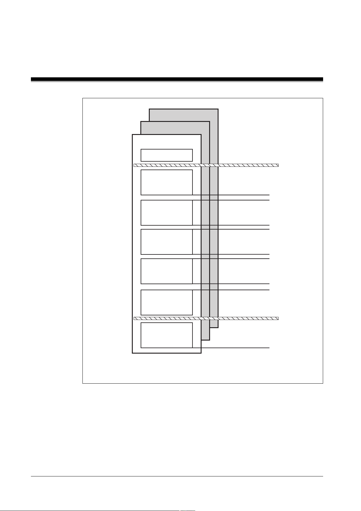
Structure of the administration data blocks
The administration data blocks DB015, DB016 and DB017 have the same
structure.
Each standard function block in the user program has 5 data words
available in one of the administration data blocks. These data words are
used to back up the temporary flags from the standard function block (see
section entitled “Temporary flag range in MBS blocks”).
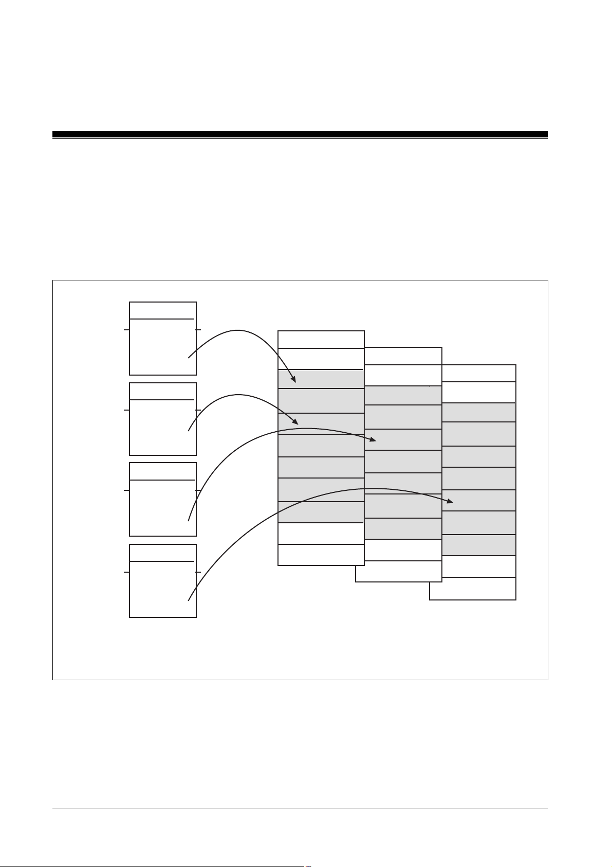
In each of the administration data blocks, the range DW0001 to DW1000 is
divided into 5 blocks, each with 200 data words (see Fig. 5-1).
5-3Modular Block System: Burner Management
Page 34
MBS Basics
DB017
DB016
DB015
DW0000
Block 1
200 data words
Block 2
200 data words
Block 3
200 data words
Block 4
200 data words
Block 5
200 data words
Block 6
Global
parameters
DW 0001
to
DW 0200
DW 0201
to
DW 0400
DW 0401
to
DW 0600
DW 0601
to
DW 0800
DW 0801
to
DW 1000
DW 1001
to
DW 1023
5-4
Fig. 5-1: Structure of the administration data blocks
Modular Block System: Burner Management
Page 35
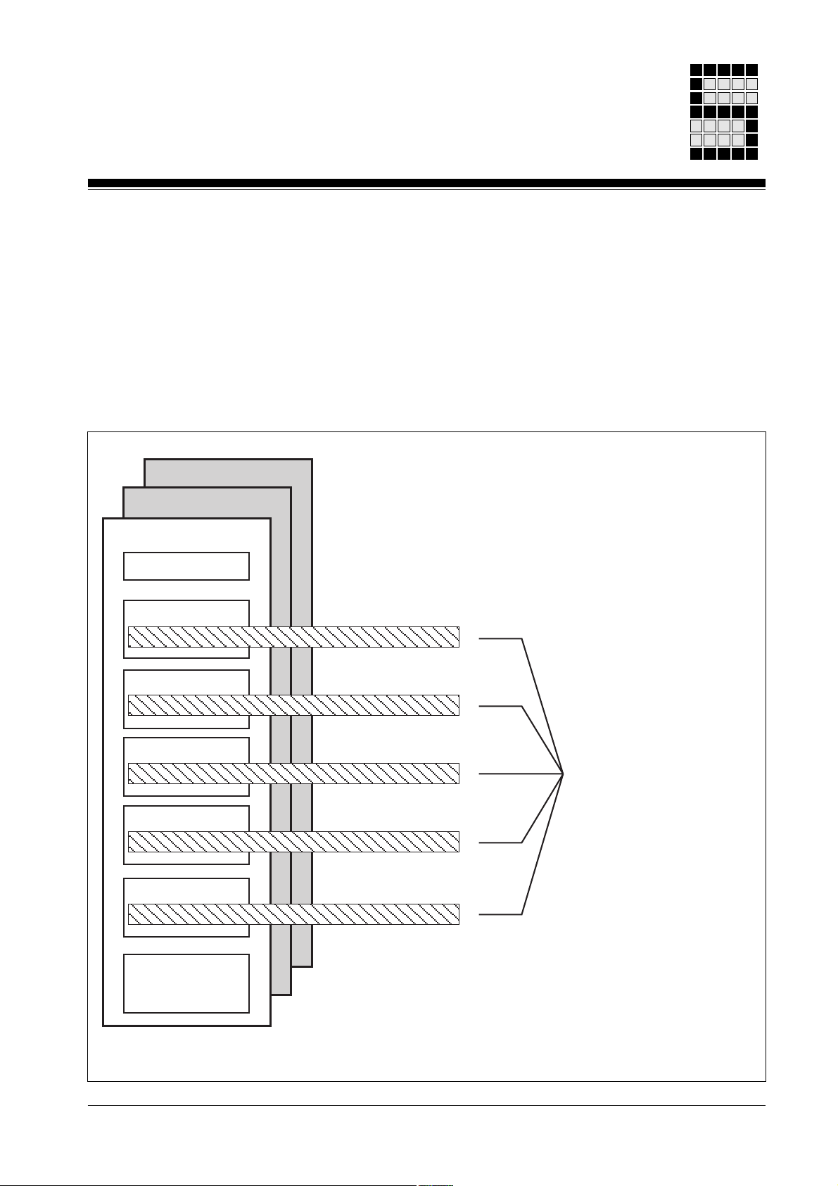
Blocks contained in the administration data blocks
Each standard function block occupies 1 data word per block (see Fig. 5-
2). This means a max. of 200 safety devices (e.g. E-STOP 1, E-STOP 2,
safety gate 1) can be managed per administration data block.
The PSS uses a standard function block’s SSNR to automatically generate
the corresponding data words (see “Input parameter SSNR”).
DB017
DB016
DB015
DW0000
Block 1
Data word 1
Block 2
Block 3
Block 4
Block 5
Block 6
Global
parameters
Data word 2
Data word 3
Data word 4
Data word 5
Fig. 5-2: Contents of the administration data blocks
Data words 1 to 5
of an MBS
standard function block
5-5Modular Block System: Burner Management
Page 36

MBS Basics
DW0000 (DB015)
1st data block (DB015/DB016/DB017):
DW 0001 ... DW0200 bits for hardware and operator errors
2nd data block ... 5. data block (DB015/DB016/DB017):
If parameters for a standard function block’s input parameter
SSNR are not within the permitted range, DW0000 of DB015
will contain the incorrect SSNR parameter. The standard
function block will not be enabled (output parameter ENBL= 0).
If the SSNR=0, DW0000 of DB015 will contain the decimal
value -1 or KH FFFF.
The significance of the individual bits can be found in the
description for the relevant standard function block (see section
entitled “Fault diagnostics”).
If a data word contains the value 0, no error has been found
DW0201 ... DW1000
Data blocks 2 ... 5 are used for internal block data.
6th data block (DB015/DB016/DB017)
DW1001 ... DW1023
Data block 6 contains the global parameters (see section
entitled “Global parameters”).
5-6
Modular Block System: Burner Management
Page 37

Input parameter SSNR
MBS standard function blocks have input and output parameters which can
be adapted to suit the respective control configuration. The input
parameter SSNR (safety subroutine number) is available on all MBS
standard function blocks. It is required to manage the administration data
blocks DB015, DB016 and DB017.
INFORMATION
MBS standard function blocks may differ in terms of the permitted value
range for the SSNR. The following value ranges are possible for the SSNR:
• Value range of input parameter SSNR: 1 ... 200
(byte constant type: KB001 ... KB200)
• Value range of input parameter SSNR: 1 ... 600
(word constant type: KF000001 ... KF000600)
The valid value range for the SSNR of a standard function block is
documented in the standard function block description.
The input parameter SSNR determines the administration data block plus
the 5 data words assigned in the administration data block of the
corresponding safety device (1 DW per block). The administration data
blocks are assigned the following SSNR ranges:
• SSNR 001 ... 200: DB015
• SSNR 201 ... 400: DB016
• SSNR 401 ... 600: DB017
The one data word per block is generated automatically internally (SSNR +
offset).
5-7Modular Block System: Burner Management
Page 38

MBS Basics
NOTICE
• One MBS standard function block must be used for each safety device.
• Each standard function block should be assigned its own SSNR.
• Make sure that each SSNR is assigned once only.
• Document the assignment of the safety device to the respective SSNR of
Example
Safety device 2 (E-STOP button) is monitored using SB061. The value
KB002 is assigned to input parameter SSNR of SB061.
If two SB calls have the same value for the SSNR, they will access the
same data word in the administration data block. This can lead to
malfunctions.
the standard function block.
The following DWs in DB015 are therefore assigned to safety device 2:
Block 1: DW0002
Block 2: DW0202
Block 3: DW0402
Block 4: DW0602
Block 5: DW0802
The user program has read-only access to these data words.
5-8
Modular Block System: Burner Management
Page 39

Fault diagnostics
Error types
On programmable safety systems from the PSS-range, a distinction is
made between two types of errors. On the one hand there are errors which
are detected and evaluated through the PSS operating system, and on the
other there are errors which are detected and evaluated through the user
program. The reaction to these two types of errors is different.
Where errors are detected through the operating system, the FS section of
the PSS will switch to a STOP condition and all outputs will be switched off
safely.
Where errors are detected through the user program, only the configured
error reaction will occur. Errors that are detected via an MBS standard
function block belong to this second type of error.
5-9Modular Block System: Burner Management
Page 40
MBS Basics
Fault diagnostics using the administration data blocks
Data words DW0001 ... DW0200 of an administration data block contain
the error messages from the individual MBS standard function blocks (see
Fig 5-3). 1 data word is reserved for each standard function block used.
The assignment is made using the SSNR.
SB061
KB001
KB005
KF000205
KF000427
SSNR
SB061
SSNR
SB065
SSNR
SB065
SSNR
FG
FG
ENBL
ENBL
DB015
DW0000
DW0001
...
DW0005
...
DW0027
...
DW0200
...
DW1023
DB016
DW0000
DW0001
...
DW0005
...
DW0027
...
DW0200
...
DW1023
DB017
DW0000
DW0001
...
DW0005
...
DW0027
...
DW0200
...
DW1023
Fig. 5-3: Managing the MBS error messages using the administration data blocks (example)
5-10
Modular Block System: Burner Management
Page 41

Temporary flag range in MBS blocks
Internally, MBS blocks use the flags in the range M 64.00 ... M69.31 as
temporary flags.
NOTICE
We recommend the following:
• Do not use flags from the temporary flag range for your own applications.
Malfunctions may occur if you use the temporary flag range M64.00 ...
M69.31 for your own applications.
• If it is absolutely necessary to use this flag range, under no
circumstances should you use the flags:
- in alarm OBs
- as input parameters for standard function blocks
- as output parameters for standard function blocks
- as global parameters
Output parameter ENBL
Many standard function blocks have an enable output ENBL. This output
parameter indicates the enable status of a standard function block. The
enable status results from the standard function block’s check of the
inputs.
ENBL = 1: No error found,
the function is enabled
ENBL = 0: An error has been found,
the function is not enabled.
5-11Modular Block System: Burner Management
Page 42

MBS Basics
Assignment of input and output parameters
Input and output parameters should be assigned in accordance with the
details given in the operating manual.
WARNING!
If several unused output parameters are connected to the same flag,
malfunctions may occur in the standard function blocks. If an unused
output has to be assigned a flag, make sure the output is assigned to a
flag that is not used anywhere else in the program.
Minimum scan time
Most of the timer functions required within the blocks are performed using
cycle counters. This means that almost all the timers are available for use
in applications.
INFORMATION
• If MBS blocks are used, a minimum scan time must always be
entered in the configurator. Empirical values should be used.
• If the error message F-20/06 (error category/error number) appears on
the CPU display, you must amend the minimum scan time appropriately.
This error message indicates that the minimum scan time has been
exceeded. The PSS must not be operated while this error message is
present.
SB070 and SB071 automatically enter the minimum scan time in DW1022
of the administration data blocks. In this way it is automatically available to
the MBS.
INFORMATION
Please note that the times are imprecise. The lack of precision on times is
due to the cyclical processing of the user program. It is determined by the
scan time of the respective user program.
In general:
The greater the ratio of time value to scan time, the greater accuracy you
will have with the required times.
5-12
Modular Block System: Burner Management
Page 43

Global parameters
Block 6 (DW1001 ... DW1023) of the administration data blocks contains
global parameters. These are parameters that are valid for several blocks.
For details of which global parameters a standard function block uses,
please refer to the description of the individual standard function blocks.
The data words in block 6 must be initialised when the program is started
(OB120) using SB070/SB071 (INIT_MBS).
The abbreviations in brackets {... : ...} at the end of each data word
correspond to the parameters in SB071. The times that are also specified
within the brackets are empirical values, unless stated otherwise.
DW1001 Number of cycles in the contact synchronisation time between
DW1002 Number of cycles in the feedback loop’s reaction time to a
DW1003 Number of cycles in the contact switchover time between a N/
DW1004 Number of cycles in the contact switchover time between a N/
DW1005 Number of cycles in the machine clock time
DW1006 Number of cycles in the permitted ESPE reaction time
DW1007 Reserved
DW1009 Reserved
DW1010 Reserved
DW1011 Reserved
DW1012 Reserved
DW1013 Reserved
DW1014 Reserved
2 N/O contacts or 2 N/C contacts (e.g. E-STOP button, reset
key, etc.)
{CoSy : 50ms}
change in the PSS output connected to the main contactor
{RFbL : 100ms}
O and N/C contact (pushbutton)
{CS_B : 100 ms}
O and N/C contact (relay)
{CS_R: 50 ms}
{MaCy : max. 30 s in accordance with EN 61496-1 section
A.8.4, 06/98}
{ESPE : max. 150 ms in accordance with EN 61496-1 section
5.2.4, 06/98}
5-13Modular Block System: Burner Management
Page 44

MBS Basics
DW1015 Counter for SSNR monitoring
DW1016 Reserved
DW1017 Reserved
DW1018 Reserved
DW1019 Reserved for administration
DW1020 Reserved
DW1021 Reserved for burner management
DW1022 Min. scan time from DB002/DW0002
DW1023 Reserved
5-14
Modular Block System: Burner Management
Page 45

Standard Function Blocks
SB149: Sequence control
Block header
Input parameters
•
•
SB149
STEP
X - RDY
X - COND
X - STEP
B - W_BA
W - W_V
Z - W_T
B - D_BA
W - D_V
Z - D_T
RDY
: Ready signal from the previous step
RDY
= 1: ready signal is present
COND
: Global input for step enabling conditions for next step
COND
= 1: all step enabling conditions fulfilled
NEXT - X
W_E - X
D_E - X
• STEP: Signals burner start-up for the duration of a cycle and
deactivates the step
STEP
= 1: first cycle of burner start-up and deactivating the
step
STEP
= 0: no burner start-up detected
This parameter must be assigned with the same operand used
for the output parameter
operator elements” and for the input parameter
STEP
from SB152 “Burner: Start and
STEP
SB157 “Ignition attempts” for the same burner.
•
W_BA
: Time base for step monitoring time (watchdog base)
Following values are valid:
0: 50 ms
1: 100 ms
2: 1 s
3: 10 s
4: 1 min
of
Modular Block System: Burner Management
6-1
Page 46

Standard Function Blocks
•
W_V
: Time value (watchdog value) of step monitoring time as
multiplier for
Permitted value range: - 32768 ... 32767
For W_V ≤ 0 to be valid: there is no step monitoring time,
the output parameter W_E is permanently 0.
• W_T: Timer (watchdog timer) for step monitoring time
• D_BA: Time base for step time delay
Following values are valid:
0: 50 ms
1: 100 ms
2: 1 s
3: 10 s
4: 1 min
•
D_V
: Time value of the time delay as multiplier for
Permitted vallue range: -32768 ... 32767
For
D_BA
the output parameter
soon as a step is activated.
≤ 0 to be valid: there is no time delay,
W_BA
D_BA
D_E
changes immediately from 0 to 1 as
SB149
•
D_T
Output parameters
•
NEXT
•
W_E
•
D_E
Function:
• Control of work cycles
• By adding together several SB149 blocks, a step sequence can be
• One PSS can control and monitor several work cycles (e.g. burner), in
: Timer for time delay
: Gives the status of the step
NEXT
: Output parameter for step monitoring time
W_E
: Output parameter for the time delay
D_E
established
which each cycle is allocated a separate sequence
= 1: step is active
= 1: timer for the step monitoring time has elapsed.
= 1: timer for the time delay has elapsed.
6-2
Modular Block System: Burner Management
Page 47

Error messages
• Each SB149 of this sequence waits for the ready signal from the
previous step and for the step enabling conditions to be fulfilled, before
it is active.
• Step monitoring time: a step provess can be monitored for a specific
time
• Time delay: a function process can be limited to a certain time, or the
process can be started after a specific time.
• Error messages in DB015
None
• Error messages on the CPU-display
Blocks required
E006: Parameter errors- the time base
W_BA
or
D_BA
does not lie
within the permitted range 0 to 4. The incorrect value will be
entered in DR0 (data byte right) of the administration data block
DB015.
• DB002: Will be made available when the configurator is called up
• DB015: Administration data block
DB015 must consist of its total length of 1024 data words and
have Read/Write access (see section “Administration data
blocks DB015, DB016 and DB017” in chapter 5).
• OB101: To call up SB149
• SB149: STEP
• SB255: To call up the operating system
Modular Block System: Burner Management
6-3
Page 48

Standard Function Blocks
Programming guidelines
•
STEP
The operand for the input parameter
assigned to the output parameter
input parameter
individual steps of the sequence to reset during burner start-up.
STEP
SB149
STEP
STEP
of SB157, if SB157 is used. This will enable the
of SB149 must also be
from SB152 and also to the
The operand for the parameter
STEP
has the value 1 for the duration of
a cycle when a positive edge of the ENBL of SB152 is detected.
If several burners are operated with one PSS, each burner must be
assigned its own STEP operand. This enables the burners to be
controlled and monitored independently.
Example:
SB157
IGNI_TRY
B - SSNR
X - SyOK
X - BIT0
X - BIT3
X - FLAs
B - ITRY
M 70.00 .Burner 1 - X - STEP
W - T_V
Z- T
RDY - X
6-4
X - RDY
X - COND
M 70.00 .Burner 1 - X - STEP
B - W_BA
W - W_V
Z - W_T
B - D_BA
W - D_V
Z - D_T
SB149
STEP
NEXT - X
W_E - X
D_E - X
Modular Block System: Burner Management
Page 49

SB152
BR_START
B - SSNR
X - NEXT
X - STRT
X - STOP
X - ERR
X - GUAR
X - AirP
X - CHAI
X - FLAs
X - FTRY
X - RUN
B - D_C
X - AuSt
X - RSET
IGNI_TRY
B - SSNR
X - SyOK
X - BIT0
X - BIT3
X - FLAs
B - ITRY
M 80.00 .Burner 2 - X - STEP
W - T_V
Z- T
ENBL - X
RDY - X
STEP - X - M 70.00 .Burner 1
SB157
RDY - X
M 80.00 .Burner 2 - X - STEP
Modular Block System: Burner Management
X - RDY
X - COND
B - W_BA
W - W_V
Z - W_T
B - D_BA
W - D_V
Z - D_T
SB149
STEP
NEXT - X
W_E - X
D_E - X
6-5
Page 50

Standard Function Blocks
SB149
SB152
BR_START
•
RDY
and
NEXT
The output parameter
the input parameter
B - SSNR
X - NEXT
X - STRT
X - STOP
X - ERR
X - GUAR
X - AirP
X - CHAI
X - FLAs
X - FTRY
X - RUN
B - D_C
X - AuSt
X - RSET
NEXT
RDY
from the current step must be supplied to
of the following step. This ensures that when
ENBL - X
RDY - X
STEP - X - M 80.00 .Burner2
the next step is activated, the previous step is deactivated, thereby
ensuring only one step is active at any given.
6-6
• Activating a step
- To activate a step: the ready signal from the previous step must be
present (
(
COND
RDY
= 1).
= 1) and all step enabling conditions must be fulfilled
- As soon as a step is active, the following occurs:
output parameter
°
the input parameter
°
parameter
if
W_V
°
if
D_V
°
otherwise
NEXT
> 0, step monitoring time
> 0, time delay
D_E
NEXT
from the step is set to 1
RDY
of the current step and also the output
from the previous step are reset to 0
W_V
is started
D_V
is started,
is immediately set to 1
Modular Block System: Burner Management
Page 51

• Deactivating a step
During burner start-up, the input parameter
STEP
is set for one cycle.
The burner’s corresponding blocks evaluate this signal and reset the
sequence.
• Starting the initial step in a sequence:
RDY
The input parameter
may not be assigned a communication flag
(M100.00 - M104.31) nor an input.
When using SB152 “Burner: Start and operator elements”, the output
parameter
STEP
is set for the duration of a cycle, and the enable
is set. This parameter can be used to start the initial step.
Version 1: no conditions for the start of the initial step
The operand for the parameter
parameter
to the input parameter
STEP
of SB149 and the same operand can also be assigned
RDY
The input for the step enabling conditions
.
STEP
can be assigned to the input
COND
can be permanently
assigned with RLO1 (M110.01).
Example:
SB149
STEP
ENBL
M 70.08 .Step_1 - X - RDY
M 110.01 .RLO1 - X - COND
M 70.08 .Step_1 - X - STEP
Version 2: conditions for the start of the initial step are present
The operand for the parameter
input parameter
Example:
L M 70.08 .Step_1
S M 70.10 .RDY Step_1
Modular Block System: Burner Management
RDY
.
B - W_BA
W - W_V
Z - W_T
B - D_BA
W - D_V
Z - D_T
STEP
NEXT - X
W_E - X
D_E - X
may not be assigned directly to the
6-7
Page 52

Standard Function Blocks
SB149
SB149
STEP
M 70.10 .RDY Step_1 - X - RDY
M 70.12 .COND Step_1 - X - COND
M 70.08 .Step_1 - X - STEP
B - W_BA
W - W_V
Z - W_T
B - D_BA
W - D_V
Z - D_T
• Step monitoring time
W_E
If the step monitoring time has elapsed and the output parameter
NEXT - X
W_E - X
D_E - X
W_E
changes from 0 to 1, this alarm must be evaluated. The responsibility for
this lies solely with the user.
An application example for step monitoring time can be found in
Chapter 8.
• Time delay
D_E
There are two options for time delay:
- Time delay can be used to carry out a function for the duration of the
time delay, or
- To start a function after this time (
D_E
= 1).
An application example for time delay can be found in Chapter 8.
• Active steps in a sequence
To avoid a dangerous situation occurring in a process, the user must
ensure that only one step is active in a sequence at any given time.
6-8
Modular Block System: Burner Management
Page 53

Timing diagrams
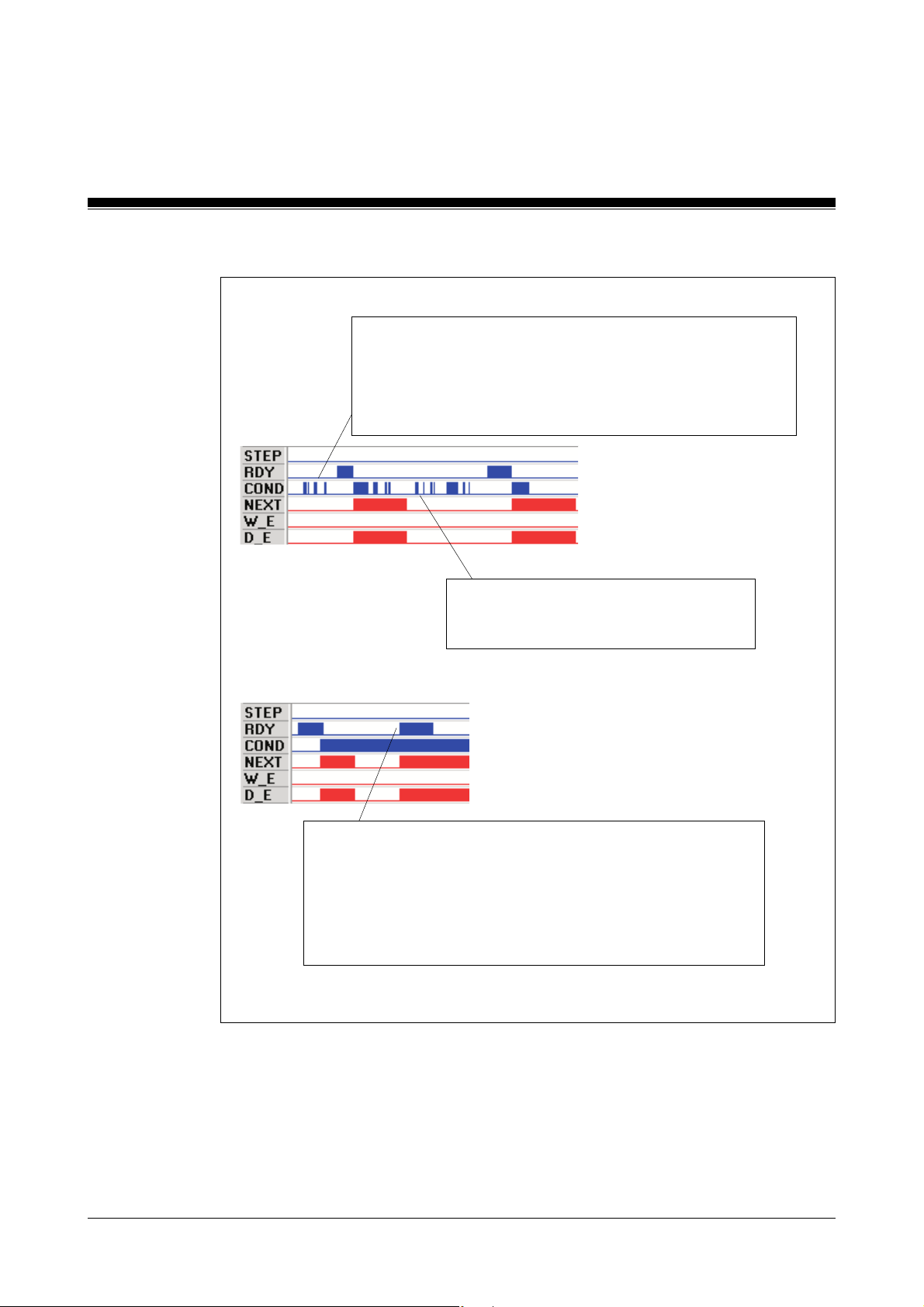
Setting / resetting the step without time delay and monitoring time
The step is activated by a “1”-Signal at the
waits for the step enabling condition at the
If the conditions are present, the
and at the same time the
When
NEXT
= 1, the
following step can be
activated.
RDY
input. The block
COND
input.
NEXT
output is set immediately,
RDY
input is reset.
The step enabling condition
must be present at the
input once only, so that the
NEXT
output is set.
If the step enabling condition is met during the
next step, then the
previous step is reset.
NEXT
COND
-
output from the
Modular Block System: Burner Management
6-9
Page 54
Standard Function Blocks
With spurious signals:
SB149
If a step enabling condition is met at the
cause the outputs to set too early.
Only if the step block was activated with
outputs react to the step enabling condition.
Repeated “1”-Signals at the
not cause malfunctions further on in the
process.
COND
RDY
COND
input, it will not
= 1 do the
input do
6-10
The
RDY
output may not be set a second time after the step
block has been run through once.
Therefore, in the FS program it must be monitored that only one
individual
have a “0”-Signal. Should it be detected that more than one
NEXT
NEXT
output is active and all other
output has a “1”-Signal, an immediate fault lockout
Modular Block System: Burner Management
NEXT
outputs
Page 55

Setting/resetting the step with time delay but without monitoring time
Instead of the next step being
activated immediately with the
NEXT
output, it can be delayed
using the
D_E
output.
The time delay
After the time has elapsed the
D_V
is started if the step enabling condition is met.
Spurious signals
Time delay
D_E
output is set.
Multiple-recurring step enabling conditions have no negative influence on the function.
The time delay
0-1 edge at the
D_V
is started once only with the initial
COND
input.
Modular Block System: Burner Management
In each case: a “1”-Signal at the STEP-input resets the
outputs NEXT and D_E.
6-11
Page 56

Standard Function Blocks
Setting/resetting the step without time delay but with monitoring time
The step enabling condition needs to be
present once only at the
NEXT
output.
COND
SB149
input to set the
The monitoring time
If the
NEXT
-output is not reset before the monitoring time cycle, the
set. This means that the step enabling condition from the following step was not
met within the permitted time.
If the step enabling condition is met later during the next step, the
and
D_E
output are reset simultaneously.
The
W_E
output can be processed further according to user requirements.
W_V
is started if all the step enabling conditions are met.
W_E
NEXT, W_E
Spurious signals:
Multiple-recurring step enabling conditions have no negative influence on the function.
The monitoring time
initial 0-1 edge at the
W_V
is started once only with the
COND
input.
output is
6-12
Monitoring time
In each case: a “1”-Signal at the
STEP input resets the outputs
NEXT, W_E and D_E.
Modular Block System: Burner Management
Page 57

Setting/resetting the step with time delay and monitoring time
Spurious signals:
The monitoring time
D_E
are started if the step enabling
condition is met.
Further processing of
is guided according to the technical
requirements of the cycles.
Multiple-recurring, fulfilled step enabling conditions have
no negative influence on the function.
The monitoring time
started once only with the initial 0-1 edge at the
input.
W_V
W_V
and the time delay
W_E
and
D_E
and the time delay
outputs
D_V
are
COND
Modular Block System: Burner Management
In each case: a “1”-Signal at the
STEP input resets the outputs
NEXT, W_E and D_E.
6-13
Page 58

Standard Function Blocks
SB150: Flame monitoring
Block header
Input parameters
•
•
SSNR
MONI
SB150
FLAME_M
B - SSNR
X - MONI
X - F_S1
X - F_S2
X - RUN
ENBL - X
: Safety subroutine number
Permitted value range: 1 ... 200
Format: Byte constants KB 001 ... KB 200
(further information about the SSNR can be found in the
sections “Administration data blocks DB015, DB016 and
SB017” and “Input parameter
SSNR
” in chapter 5).
Value of DW0000/DB015 = 0: no error present
:
MONI
When
When
The output parameter
= 1: carries out flame monitoring:
RUN
= 1: monitoring for “ flame established”
RUN
= 0: monitoring for “flame not established”
FLAI
from SB158 “Ignition” must be
supplied to this parameter when using SB150 for pilot flame
monitoring, and the output parameter
FLAM
from SB159 “Run”
must be supplied to this parameter when using SB150 for main
flame monitoring.
6-14
•
F_S1
•
F_S2
•
RUN
: Flame signal (N/O contact)
F_S1
= 1: flame established
: Flame signal (N/C contact)
F_S2
= 1: flame not established
: The output parameter
RUN
from SB158 “Ignition” must be
supplied to this parameter when using SB150 for pilot flame
monitoring, so that information about the status of the pilot
flame can be obtained. The output parameter
RUN
SB159 “Run” must be supplied to the input parameter
from SB150 when using SB150 for main flame monitoring.
RUN
= 1: monitoring for “flame established”
Modular Block System: Burner Management
from
RUN
Page 59

Output parameters
Function:
Error messages
ENBL
Pilot and main flame monitoring from burner start-up to operating position,
through to burner switch-off.
Any fault that is detected will be stored statically in the corresponding error
data word (SSNR) of DB015 (1st data block).
• Error messages in DB 015
: Enable flag bit
ENBL
(refer also to the Programming guidelines)
- Bit00: Burner in operating position but no flame established
- Bit01: Burner not in the operating position, but the flame is established
= 1: this function is fault-free
Remedy: Exit operating position (
and bring SB150 to the start position (
F_S2
Remedy: Bring SB150 to the start position (
0,
= 1,
F_S2
RUN
= 1,
= 0).
RUN
= 0).
RUN
= 0),
MONI
= 1,
MONI
F_S1
= 1,
= 0,
F_S1
=
- Bit02: Burner in the operating position and both flame monitor
contacts (
Remedy: Exit operating position (
monitors' contacts and bring SB150 to the start position
(
MONI
- Bit03: Burner in operating position and both flame monitor contacts
(
F_S1
Remedy: Exit operating position (
monitor contacts and bring SB150 to the start position (
= 1,
- Bit04: Burner not in the operating position and both flame monitor
contacts (
Remedy: Check flame monitor contacts and bring SB150 to the
start position(
- Bit05: Burner not in the operating position and both flame monitor
contacts (
Remedy: Check flame monitor contacts and bring SB150 to
the start position (
= 1,
and
F_S1
F_S1
F_S1
F_S2
= 0,
F_S1
MONI
F_S1
and
F_S2
) have the value 1.
= 0,
F_S2
= 1,
) have the value 0
F_S2
and
and
MONI
= 1,
RUN
F_S2
) have the value 1
= 1,
F_S1
F_S2
) have the value 0
= 1,
F_S1
RUN
RUN
RUN
= 0).
= 0,
= 0), check flame
= 0).
= 0), check flame
F_S2
= 1,
RUN
= 0,
F_S2
= 1,
= 0).
RUN
MONI
= 0).
Modular Block System: Burner Management
6-15
Page 60

Standard Function Blocks
- Bit07: Flame established but does not correspond to the expected
status
Remedy: Exit operating position (
to the start position (
- Bit08: Flame monitoring switched off
Remedy: Switch on flame monitoring (
SB150 to the start position (
RUN
= 0).
• Error messagess on the CPU-display
E001: Parameter errors
The
SSNR
SSNR
“Administration data blocks DB015, DB016 and DB017” in
chapter 5).
does not lie within the limits 1 ... 200. The incorrect
is stated in DB015/DW0000 (see the section
MONI
= 1,
F_S1
MONI
RUN
= 0) and bring the SB150
= 0,
F_S2
= 1,
MONI
= 1,
= 1) and bring
F_S1
= 0,
F_S2
SB150
RUN
= 0).
= 1,
Blocks required
• DB002: Will be made available when the configurator is called up.
• DB015: Administration data block
DB015 must consist of its total length of 1024 words and have
Read/Write status (refer also to the section “Administration data
blocks DB015, DB016 and DB017" in chapter 5).
• OB101: To call up SB(s)150 directly in OB101 or, for example, together
in an FB.
• SB150: FLAME_M
• SB152: BR_START for evaluating the flame monitor global signal
FLAs.
• SB157: IGNI_TRY for evaluating the flame monitor global signal
when carring out several ignition attempts.
FLAs
6-16
Modular Block System: Burner Management
Page 61

• SB158: IGNITION for deciding about pilot flame monitoring.
• SB159: RUN for decision about monitoring the main flame.
• SB255: To call up the operating system.
Programming guidelines
•
ENBL
The enables for all SB150 blocks must be AND-connected in the
application program after being called up. The result of this bit operation
must be supplied to the input parameter
and operator elements”.
The enables of the active SB150 blocks for pilot flame monitoring must
be supplied and additionally AND-connected to the input parameter
FLAs
of SB157 “Ignition attempts”, if SB157 is used.
A programming example can be found in Chapter 8 under “Managing
enables”.
• Main flame monitoring after an error
FLAs
of SB152 “Burner: Start
If the main flame is in the operating position and the plant is shutdown
because an error occurs (e.g. monitor sequence broken), the flame
monitor receives the command to check the flame for “flame established”
in the next cycle. On some plants, the flame does not extinguish
immediately after switch-off i.e. within a cycle. In these cases, a fault will
result. To avoid this, a time
negative edge at the plant enable (
this time, the flame monitor will not be evaluated (
D_V
can be started via step (SB149) when a
ENBL
of SB152) is detected. During
MONI
= 0). After this
time cycle SB159 “Run” assumes control of flame monitoring.
Programming example:
LN M74.00 .ENBL SB 152
U M73.01 .Auxiliary flag, negative edge ENBL
= M73.02 .Pulse flag
R M73.01 .Auxiliary flag, negative edge ENBL
1
L M74.00 .ENBL SB 152
S M73.01 .Auxiliary flag, negative edge ENBL
Modular Block System: Burner Management
6-17
Page 62

Standard Function Blocks
SB159
RUN
SB150
SSNR
NEXT
SyOK
SB152
BR_START
SSNR
NEXT
STRT
STOP
ERR
GUAR
AirP
CHAI
FLAs
FTRY
RUN
D_C
AuSt
RSET
ENBL
RDY
VAV3
REGL
RUN
FLAM
ENBL
RDY
STEP
Pulse
1
Time value for
time delay
&
RDY
COND
STEP
W_BA
W_V
W_T
D_BA
D_V
D_T
SB149
STEP
NEXT
W_E
D_E
&
&
&
S R Q
>1
SB150
FLAME_M
SSNR
MONI
F_S1
F_S2
RUN
ENBL
Fig. 6-1: Main flame monitoring after a fault
6-18
Modular Block System: Burner Management
Page 63

Timing diagrams
Signal cycle with an uninterrupted burner start-up or uninterrupted burner stop sequence
Monitoring for “Flame not established”
A “1”-Signal at the
F_S2
are monitored for “0” and “1” respectively, i.e. for “flame not established”.
During the ignition process, the signals at
SB 150 must change from detecting for “flame not established” to detecting
for “flame established”. During this switching time the
are not evaluated: they can have any status.
MONI
input and a “0”-Signal at the
Monitoring for “flame established”
A “1”-Signal at the
Signal at the
monitored for “1” and
”flame not established”.
RUN
input,
F_S1
and
F_S1
and
F_S2
must change, i.e.
F_S1/F_S2
MONI
RUN
-input means
If the
MONI
input is reset,
monitoring is deactivated and the
flame can be extinguished
without the block generating an
error message (
ENBL
-inputs
input and a “1”-
F_S1
F_S2
for “0”, i.e. for
= 0).
is
Modular Block System: Burner Management
6-19
Page 64

Standard Function Blocks
Flame monitor error
Flame monitor fault when monitoring for
“flame not established”.
SB150
After the
Signals at
Monitoring for “flame established” must be first run through without
error, before switching to monitoring for “flame established” can be
carried out.
ENBL
-output is reset, an enable is not set even with valid “1”-
F_S1
and
RUN.
Spurious signals when monitoring for “flame not established”
Spurious signals /
signal combinations
at
F_S1
and
F_S2
do
have no effect on the
block’s function.
If there is a “1”-Signal at
the MONI input,
F_S2
monitoring is active
and reacts immediately
when the
reset.
ENBL
F_S1/
output is
Only the permitted signal
combination at
F_S2
can reactivate the
enable.
F_S1/
6-20
Invalid signals deactivate the enable. The enable signals processed in other
program sections (flame monitor sequence, SB 152) will, via this program
section, trigger the burner to shutdown.
The enable signal will be issued again only if the inputs are
F_S1
= 0. With other signal combinations, the enable remains cancelled.
Modular Block System: Burner Management
F_S2
= 1 and
Page 65

Spurious signals before and during monitoring for “flame established”
No spurious enable via
interference signals
possible.
Spurious signals during monitoring for “flame established”
Flame established,
monitoring active.
Only the fault-free signals
F_S2
= 1,
F_S1
= 0 and the
MONI
input set the
output.
Shutdown due to flame
failure.
No spurious enable can be
generated due to
interference signals.
ENBL
Modular Block System: Burner Management
6-21
Page 66

Standard Function Blocks
SB151: Transient suppression
Block header
Input parameters
•
SSNR
SB151
BridgedS
B - SSNR
X- S1
X - BASE
W - T_V
Z- T
X - AuSt
X - RSET
ENBL - X
: Safety subroutine number
Permitted value range: 1 ... 200
Format: Byte-constants KB001 ... KB200
(further infotmation about the
SSNR
can be found in the
sections “Administration data blocks DB015, DB016 and
DB017” and “Input parameter
SSNR
” in chapter 5).
Value of DW0000/DB015 = 0: no error present
•S1: N/C contact to be monitored (check with test pulse)
•
BASE
•
T_V
: Setting the time base
BASE
T_V
BASE
by
: Multiplier for
= M110.00 (RLO = 0): time base of 50 ms, multiplied by
gives a possible range of 50 ms to 27.3 min
= M110.01 (RLO = 1): time base of 100 ms, multiplied
T_V
gives a possible time range of 100 ms to 54,6 min
BASE
, to determine the length of time the enable
signal should be delayed
Permitted value range: 1 ... 32767
•T: Timer, which measures the set time
•
AuSt
: Automatic start (reset)
AuSt
= M110.01 (RLO =1): automatic start (without reset)
AuSt
= M110.00 (RLO =0): no automatic start
•
RSET
: Reset button (N/O)
6-22
Modular Block System: Burner Management
Page 67

Output parameters
Function
Error messages
ENBL
: Enable flag bit
ENBL
= 1: the signal at the N/C contact S1 is fault-free
(refer also to Programming guidelines)
Spurious signals at the monitored input (e.g. a pressure monitor) cancels
the enable after a set time.
If the N/C contact functions without fault, SB151 sets the enable
ENBL
. If
interference occurs, the enable is cancelled after a set time period. Short,
fleeting interferences, for example, pressure swings after the valve has
opened will have no effect on the enable.
Any fault that is detected will be stored statically in the corresponding error
data word (SSNR) of DB015 (1st data block).
• Error messages in DB015
- Bit 09: Suppression time has elapsed, the signal is spurious
Remedy: check contact S1 and if
button
RSET
.
AuSt
= 0, press the reset
- Bit 14: Reset button
RSET
pressed continuously or pressed too soon.
Remedy: Release reset button and press again.
- Bit 15: Signal is fault-free, but the error which occurred was not reset
(
RSET
Remedy: press the reset button
missing)
RSET
.
• Error Messages on the CPU-display
- E001: Parameter errors
The
SSNR
incorrect
does not lie within the limits of 1 ... 200. The
SSNR
is stated in DB015/DW0000 (refer also to the
section “Administration data blocks DB015, DB016 and DB017”
in chapter 5).
- E007: Invalid time value for
T_V
Modular Block System: Burner Management
6-23
Page 68

Standard Function Blocks
Blocks required
• DB002: Will be made available when the configurator is called up.
• DB015: Administration data block
DB015 must consist of its total length of 1024 data words and
have Read/Write status (refer also to the section “Administration data blocks DB015, DB016 and DB017” in chapter 5).
• OB101: To call up SB 151
• SB151: BridgedS
• SB152: BR_START for the error reaction
• SB255: To call up the operating system
Programming guidelines
ENBL
SB151
The enable
before the global input
input
CHAI
to use
regarding error reactions.
ERR
: If an error occurs, a controlled shutdown is carried out when
CHAI
: If an error occurs, a safety shutdown is carried out.
A programming example can be found in Chapter 8 under “Managing
enables”.
ENBL
of SB152 “Burner: Start and operator elements”. The decision
ERR
or
AuSt
from SB151 must be supplied to the AND-operation
ERR
or to the AND-operation before the global
CHAI
depends on the user and the respective standards
= 1 with restart.
6-24
Modular Block System: Burner Management
Page 69

Timing diagrams
Setting the
ENBL
output automatically when the signal is recovered
A failure of S1 for a time less than the block set time means the
ENBL
output does not switch to "0".
Only if S1 drops out for a longer period of time will the
reset.
The
ENBL
output is set immediately without the
need for intervention.
ENBL
output
Setting the
ENBL
output after a reset when the signal is recovered
A failure of S1 for a length of time less than the block set time
means the
Only if S1 fails for a longer period of time will the
reset.
ENBL
output does not switch to "0".
With signal recovery the
is set only after a reset signal.
ENBL
output
ENBL
output
Modular Block System: Burner Management
6-25
Page 70

Standard Function Blocks
SB151
Spurious signal sequence at
Spurious signal sequence at
BASE
AuSt
input
According to the alloted time base, the set time is
decreased (
counter value at the
time base, giving the required time.
BASE
= 0) or increased (
T_V
BASE
= 1). The
-input is multiplied with the
input
6-26
Changing from “manual reset” (
reset” (
system start after a signal change at the
re-assigning the parameter, down-loading a re-linked
program and restarting the system.
AuSt
= 1) can only be achieved by a new
AuSt
= 0) to “automatic
AuSt
input, i.e.
Modular Block System: Burner Management
Page 71

Notes
Modular Block System: Burner Management
6-27
Page 72

Standard Function Blocks
SB152: Burner: start and operator elements
SB152
Block header
Input parameters
•
SSNR
SB152
BR_START
B - SSNR
X - NEXT
X - STRT
X - STOP
X - ERR
X - GUAR
X - AirP
X - CHAI
X - FLAs
X - FTRY
X - RUN
B - D_C
X - AuSt
X - RSET
ENBL - X
RDY - X
STEP - X
: Safety subroutine number
Permitted value range: 1 ... 200
Format: Byte-constants KB001 ... KB200
(further information about the
SSNR
can be found in the
sections “Administration data blocks DB015, DB016 and
DB017” and “Input parameter
SSNR
” in chapter 5).
Value of DW0000/DB015 = 0: no error detected.
6-28
•
NEXT
•
STRT
•
STOP
•
ERR
:
NEXT
= 1: Time for the step “Build-up minimum air pressure”
has elapsed, air pressure monitoring is activated (air pressure
monitor
AirP
) .
: Start input to switch on the burner
: Stop input to switch off the burner
: Global input of the error sequence
ERR
= 0: controlled shutdown when
safety shutdown when
ERR
= 1: the error sequence is inactive, which means no error
AuSt
AuSt
= 0
= 1,
is present.
Modular Block System: Burner Management
Page 73

•
GUAR
•
AirP
•
CHAI
•
FLAs
•
FTRY
•
RUN
: Global input of the monitor sequence
GUAR
shutdown when
GUAR
: Air pressure monitor
AirP
AirP
: Global input of the safety sequence
CHAI
CHAI
: Global input of the flame signals
FLAs
FLAs
:
FTRY
flame error in operation (only possible if AuSt = 1)
FTRY
fault lock-out occurs.
: The output parameter
supplied to this parameter, so information about the operating
status of the main flame can be obtained."
RUN
= 0: controlled shutdown when
AuSt
= 0
= 1: monitor sequence is inactive: no error is present
= 1: minimum air pressure is present
= 0: air pressure is below the minimum
= 0: safety shutdown
= 1: the safety equence is inactive: no error is present
= 0: fault lock-out
= 1: flame signlas are fault-free
= M110.01 (RLO =1): single attemptat a restart after a
= M110.00 (RLO =0): no option for automatic restart, a
RUN
from SB159 “Run” must be
= 1: operating position.
AuSt
= 1, safety
• D_C: Contains the number of cycles for the delayed enable of
SB152 after the PSS has started-up. The delayed enable is
required so that the flame monitors can reach a defined
position without a fault lock-out occurring.
Example: If the minimum scan time is 50 ms and the delayed
•
AuSt
•
RSET
enable 5 s, the parameter
: Automatic start (reset) when the PSS starts up
AuSt
= M110.01 (RLO =1): automatic start (without reset) is
required after a controlled shutdown
AuSt
= M110.00 (RLO =0): no automatic start required after a
controlled shutdown
: Reset button (N/O)
D_C
must be assigned KB100
Modular Block System: Burner Management
6-29
Page 74

Standard Function Blocks
Output parameters
•
Function
ENBL
•
RDY
• STEP: signals burner stat-up for the duration of a cycle.
: Enable flag bit
ENBL
(see also Programming guidelines)
: Ready signal
RDY
correctly. The next step of the sequence is enabled.
STEP
STEP
This parameter must be assigned with the operand also
assigned to the input parameter
“Ignition attempts” for the same burner.
= 1: this function is fault-free
= 1: the step “Build up minimum air pressure” ended
= 1: first cycle of burner start-up
= 0: no burner start-up detected
STEP
SB152
of SB149 and SB157
• Monitoring the flames (pilot and main flames) from burner start-up to
operating position until burner switch-off (controlled or safety shutdown
or fault lock-out)
• Restart after a controlled shutdown
• Allows a restart once only after a controlled shutdown, which has been
triggered because of a flame failure during operation.
• Monitoring the air pressure monitor, after the time has elapsed for
building-up minimum air pressure.
• Evaluating the reset, start and stop button
• Monitoring global signals from the error, monitor and safety sequences
• Carrying out a delayed start-up after the system has started so that the
safety, error, monitor and flame monitoring sequences can supply a
positive acknowledgement signal for the global signal inputs.
6-30
Modular Block System: Burner Management
Page 75

Error messages
Any fault that is detected will be stored statically in the corresponding error
data word (SSNR) of DB015 (1st data block).
• Error messages in DB015
- Bit 00: Flame signal sequence interrupted: fault lock-out occurs
Remedy: First press the reset button (
button (
STRT
)
RSET
) and then the start
- Bit 01: Safety sequence is interrupted: controlled shutdown occurs
Remedy: First press the reset button (
button (
STRT
).
RSET
) a then the start
- Bit 02: Error sequence is interrupted: controlled shutdown occurs
Remedy: If
inactiveagain, otherwise press the reset button (
then press the start button (
AuSt
= 1, wait until the error sequence is
STRT
).
RSET)
and
- Bit 03: Monitor sequence is interrupted: controlled shutdown occurs
Remedy: If
again, otherwise press the reset button (
start button (
AuSt
= 1, wait until the monitor sequence is inactive
STRT
RSET
).
) and then the
- Bit 04: Minimum air pressure at start-up was not achieved after step
“Build up minimum air pressure”: safety shutdown occurs
Remedy: First press the reset button (
button (
STRT
).
RSET
) and then the start
- Bit 05: Below minimum air pressure during operation: controlled
shutdown occurs
Remedy: If
minimum air pressure, otherwise press the reset button (
and then the start button (
AuSt
= 1, wait for the air pressure monitor to signal
STRT
).
RSET
- Bit 06: Stop triggered by pressing the stop button
Remedy: Press the start button (
STRT
).
- Bit 07: Flame signal sequence is interrupted: controlled shutdown
occurs
Remedy: If
inactive again, otherwise press the reset button (
AuSt
= 1, wait for the flame signal sequence to be
RSET
) and
)
Modular Block System: Burner Management
6-31
Page 76

Standard Function Blocks
SB152
then press the start button (
- Bit 08: Reset via
Remedy: Press the reset button (
- Bit 09: Start button pressed (
value 1
Remedy: Check the stop button (
- Bit 10: Stop button pressed (
Remedy: Check start button
- Bit 11: Pressign start (
Remedy: Press the start button (
- Bit 12: Time delay for the plant enable after the PSS has started is
running
Remedy: Let the time delay run and following that, press the
start button (
- Bit 13: An error is present. Evaluation of the reset or start button
occurs only if the burner is no longer operating.
Remedy: Input parameter
reset this parameter if shutdown occurs.
RSET
STRT
STRT
is missing
STRT
STOP
) button is missing
).
STRT
), but
), but
STRT
RUN
).
RSET
STOP
STOP
STRT
STRT
must be 0, i.e. SB159 must
)
has a constant
)
has a constant value 1
.
)
Blocks required
• Error messages on the CPU-display
E001: Parameter errors
The
SSNR
SSNR
“Administration data blocks DB015, DB016 and DB017” in
chapter 5).
• DB002: Will be made available when the configurator is called up
• DB015: Administration data block
DB015 must consist of its total length of 1024 words and have
Read/Write status (see also the section “Administration data
blocks DB015, DB016 and DB017” in chapter 5).
• OB101: To call up SB152.
• SB152: BR_START
• SB255: To call up the operating system
does not lie within the limits 1 ... 200. The incorrect
is stated in the D015/DW0000 (see the section
6-32
Modular Block System: Burner Management
Page 77

Programming guidelines
• Use the global inputs for the error sequence
sequence
GUAR
and the safety sequence
ERR,
CHAI
the monitor
An automatic restart due to an interrupted error sequence or monitor
sequence is only possible, if the error sequence or monitor sequence is
reset and
AuSt
= 1.
If the safety sequence is interrupted, the error must be removed and a
manual reset carried out via the reset (
(
STRT
)! The block enable will only be issued if the safety sequence is
RSET
) and the start button
reset and no longer interrupted.
NOTICE
The error reaction is the sole responsibility of the user. When
selecting elements for error, monitor and safety sequences, all the
safety-related aspects must be taken into account!
A programming example can be found in Chapter 8 under “Managing
enables”.
• Linking the output parameter
ENBL
To ensure the valve seal if a shutdown occurs, the operand assigned to
the
ENBL
must be assigned to the input parameters
SyOK
of SB156
“Tightness Control” (if available), of SB158 “Ignition” and SB159 “Run”.
To control the ignition attempts, the operand assigned used for the
must also be assigned to the input parameter
SyOK
of SB157 “Ignition
Attempts”
ENBL
• Linking the output parameter
The operand for the output parameter
assigned to the input parameter
parameter STEP of SB157, if SB157 is used. This will enable the
individual steps of the sequence to reset during burner start-up.
The operand for the parameter
a cycle when a positive edge of the ENBL of SB152 is detected.
If several burners are operated with one PSS, each burner must be
assigned its own STEP operand. This enables the burners to be
controlled and monitored separately (see example under the description
of SB149).
Modular Block System: Burner Management
STEP
STEP
STEP
STEP
from SB152 must also be
of SB149 and also to the input
has the value 1 for the duration of
6-33
Page 78

Standard Function Blocks
Timing diagrams
Burner start-up without automatic start after a controlled shutdown
The
ENBL
output is set with a start pulse,
provided all criteria are fulfilled (
GUAR, CHAI, FLAs
With each burner start-up, a pulse at the
STEP output is created, with which all
SB149 blocks and SB 157 are reset.
).
ERR
,
With a pulse at
air pressure monitoring
is activated
SB152
NEXT,
Failure of air pressure during
burner operation (
ENBL
is reset.
Only after a reset signal can the
be set again via a start pulse. No automatic
restart is enabled.
RUN
=1 ):
If the monitor sequence is energised
(
GUAR
= 0), the behaviour is identical
to that of air pressure monitoring.
ENBL
-output
Failure of safety sequence, flame monitor sequence and general faults
Failure of one of the followign criteria
• Safety sequence
• Flame monitor sequence
• Error sequence
6-34
CHAI
ERR
= 0,
= 0
FLAs
= 0,
Modular Block System: Burner Management
Page 79

causes the output
ENBL
to be set to “0” and will only be set back to “1”, if:
• The failed criteria is once again fulfilled, i.e. at “1”.
• A reset followed, this means a pulse was issued to the
• And a start pulse was issued to the
STRT
input.
RSET
input
Please note: The short signals at the inputs are spurious signals. They
are to be expected and will not trigger a fault.
Failure of monitor sequence
Modular Block System: Burner Management
6-35
Page 80
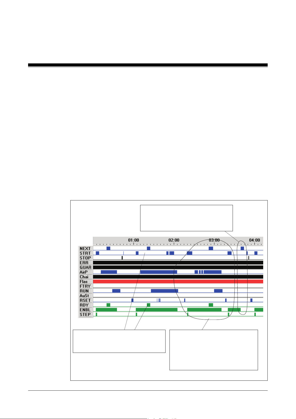
Standard Function Blocks
Monitoring of air pressure
SB152 is designed for the safe monitoring of air pressure build-up, which
should be carried out during burner start-up and continual air pressure
monitoring while the burner is operating. If there is insufficient air SB152
resets the enable i.e.
ENBL
SB152
output.
After a start pulse, a delayed air pressure signal must appear at the
AirP
input. Until the air pressure is built up, the waiting time is determined via
the ventilators and flaps. Continuous air pressure monitoring is activated
via a pulse at the
immediately if the air pressure is insufficient (
NEXT
input. Afterwards, SB152 resets the
AirP
= 0).
ENBL
output
Please note: The short signals at the inputs are spurious signals. They
are to be expected and will not trigger a fault.
When activating air pressure monitoring
with NEXT = 1 and a “1”-Signal is not
present at the AirP input, the ENBL output
is reset.
6-36
The
ENBL
output is not set.
It can only be started again after a
reset.
Air pressure monitoring will only be
activated after a pulse at the
input.
Before this, the signal at the input
AirP
can drop out, without burner
start-up needing to be interrupted.
Modular Block System: Burner Management
NEXT
Page 81
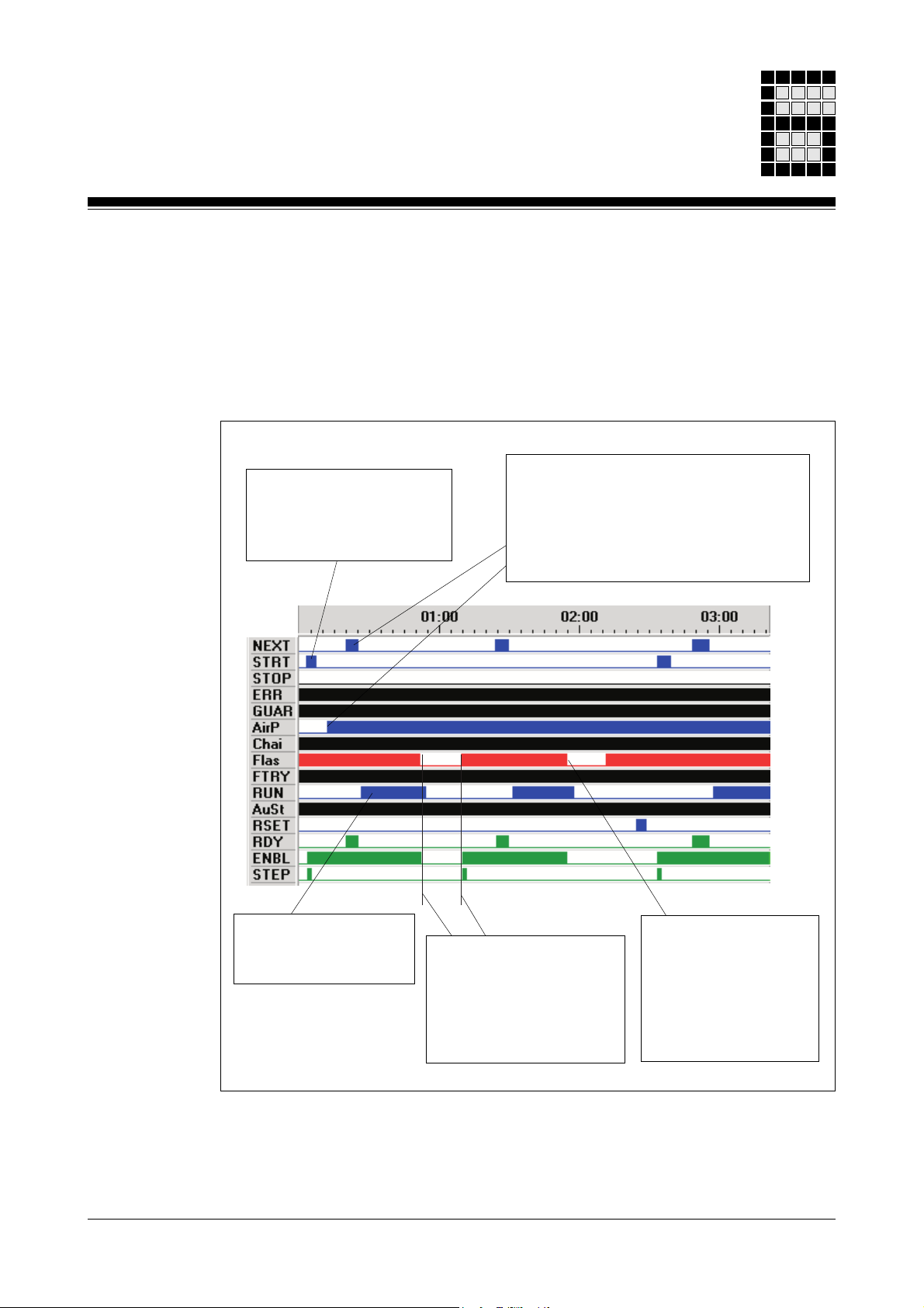
Restart after flame failure or flame monitoring fault
When
AuSt
= 1 and
FTRY
= 1 SB152 can begin an automatic restart once
only after flame failure or flame monitor interference. Burner start-up will
only be initiated if the safety sequence and the monitor sequence have not
responded, no interference is present and the flame and the flame
monitoring block does not signal a fault.
The
ENBL
output is set by
a start pulse, provided all
criteria are met (
GUAR, CHAI, FLAs
ERR
)
,
After air pressure has been built-up,
monitoring is activated by a pulse at the
NEXT
input. The
activation.
The
RDY
output is used as the step
enabling condition for the sequence.
RDY
output signals this
When
RUN
= 1,
“Burner in operation” is
signalled.
Modular Block System: Burner Management
Flame failure of flame
monitor interference.
The
ENBL
is reset
After the interference is
removed (
ENBL
FLAs
= 1), the
output is set again.
By a new, second
flame failure or flame
monitor fault, the
ENBL
output is not set
again. Only after a
reset and a start pulse
is the
ENBL
set again.
6-37
Page 82
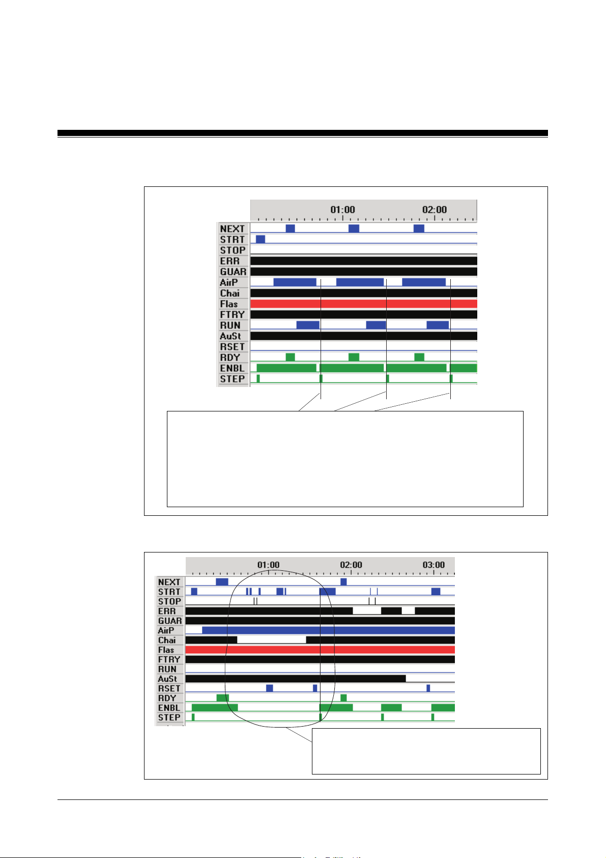
Standard Function Blocks
Automatic restart after air deficiency
SB152
Spurious signals
When
immediately if the input conditions are fulfilled after air pressure failure
i.e.
If correct air pressure is present again, monitoring can be activated with
and then the next step can be carried out. With each burner start-up, a pulse
is created at the
reset.
AirP
AuSt
= 0
= 1 and
STEP
FTRY
= 1, SB152 sets its ENBL and STEP output
NEXT
output with which all SB149 blocks and SB157 are
6-38
No irregularities with a safety sequence failure.
ENBL
= 1 only after a reset, a de-energised
monitor sequence and start pulse. geschlosse-
Modular Block System: Burner Management
Page 83
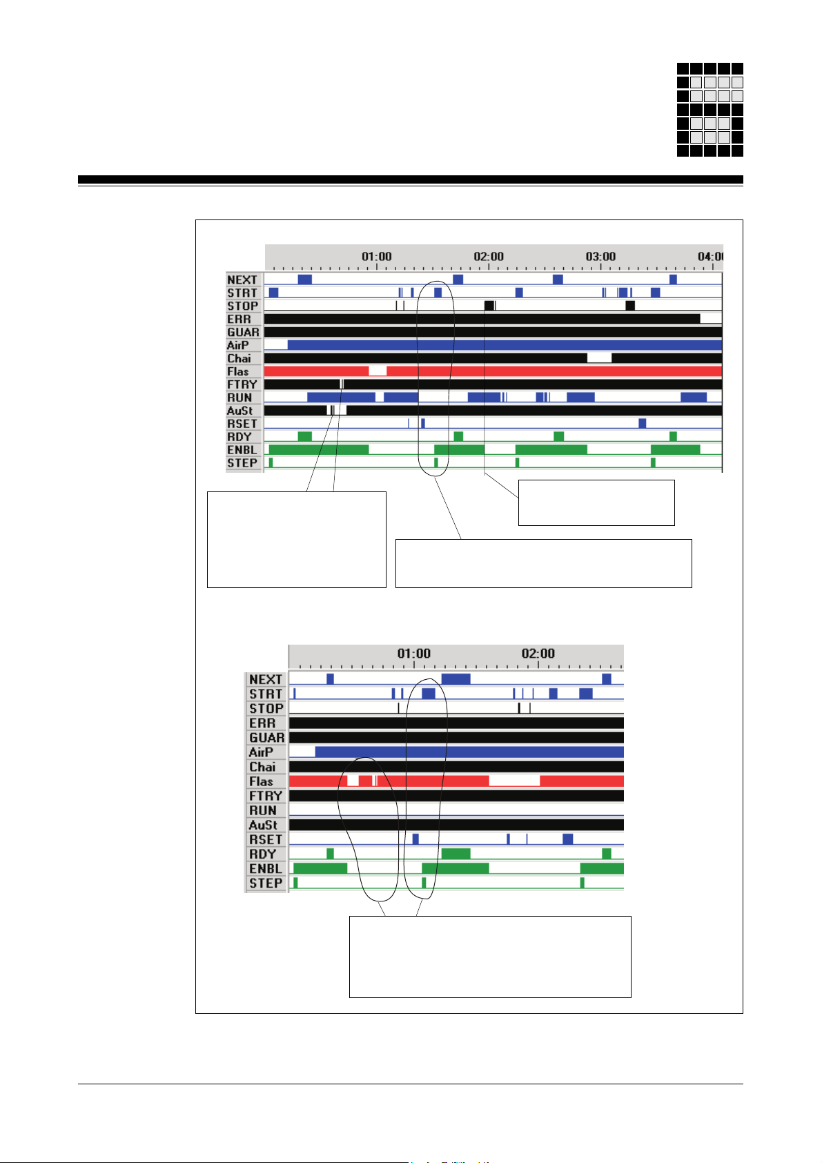
No fault due to spurious
signals at
With a
ENBL
FTRY
and
AuSt
FLAs
drop out, the
is reset correctly.
.
Correct setting of the
RSET
and a follow-on
Correct reset of the
ENBL
-output.
ENBL
output after
STRT
signal.
Modular Block System: Burner Management
If
FTRY
= 0 there is no automatic restart
after a flame failure.
START
pulse.
is only after a reset and a start
6-39
Page 84

Standard Function Blocks
SB153: Control and position monitoring of flaps
Block header
Input parameters
•
SSNR
SB153
FLAP
B - SSNR
X- C!
X- O!
X - DirO
X - DirC
W - T_V
Z- T
X - RSET
ENBL - X
OPEN - X
CLOS - X
: Safety subroutine number
Permitted value range: 1 ... 200
Format: Byte-constants KB001 ... KB200
(further information about the
SSNR
can be found in the
sections “Administration data blocks DB015, DB016 and
DB017” and “Input parameter
SSNR
” in chapter 5).
Value of DW0000/DB015 = 0: no error is present
•C!: Limit switch (N/O contact “flap closed”)
C!
= 1: the flap is closed and operated via the limit switch
C!
= 0: limit switch not operated
•O!: Limit switch (N/O contact “flap open”)
O!
= 1: the flap is opened and operated via the limit switch
O!
= 0: limit switch not operated
•
DirO
: Drive direction
positive edge from
DirO
: flap should be opened (output
= 1, until the limit switch O! is achieved)
•
DirC
: Drive direction
positive edge from
DirC
: flap should be closed (output
= 1)
•
T_V
: Switch time for the position change,
Permitted value range: 1 ... 32767,
multiplying the value with the fixed time base of
50 ms gives a time range from 50 ms ... 27.3 min.
OPEN
CLOS
6-40
Modular Block System: Burner Management
Page 85

•T: Timer which measures the time
•
RSET
Output parameters
•
ENBL
•
OPEN:OPEN
•
CLOS
Function
• Monitoring the flap status (open/closed), the direction of the change in
position and the reaction time due to a change in position
• Opening and closing a flap after a received request
• The contact-bounce time due to a change in position is one cycle.
: reset button (N/O)
: Enable flag bit
ENBL
= 1: this function is fault-free
= 1: open flap
:
OPEN
CLOS
CLOS
= 0: no drive direction “open”
= 1: close flap
= 0: no drive direction “close”
T_V
Error messages
Any fault that is detected will be stored statically in the corresponding error
data word (SSNR) of DB015 (1st data block).
• Error messages in DB015
- Bit 00: Status of contact C! does not correspond to the previous drive
direction.
Remedy: Check the limit switch and the switch time
T_V
and
reset the error. If neither limit switch is operated, the drive
direction must be re-selected.
- Bit 01: Status of contact O! does not correspond with the previous
drive direction.
Remedy: Check the limit switch and switch time
T_V
and reset
the error. If neither limit switch is operated, the drive direction
must be re-selected.
Modular Block System: Burner Management
6-41
Page 86

Standard Function Blocks
- Bit 02: Switch time for the change in position is exceeded.
Remedy: check the switch time
the error.
SB153
T_V
for the contact(s) and reset
- Bit 03:
- Bit 04: Feasibility check: neither limit switch operated.
- Bit 05: Feasibility check: both limit switches operated.
- Bit 06: Reset button not operated
- Bit 07: A new drive direction selected
• Error messages on the CPU-display
- E001: Parameter errors
DirO
and
DirC
driven simultaneously
Remedy: Only drive in one direction and reset the error. If
neither limit switch is operated, the drive direction must be reselected.
Remedy: Check contacts and reset the error. Subsequently if
neither limit switch is operated, the drive direction must be reselected.
Remedy: check contacts and reset error.
Remedy: Press reset button
Remedy: Create a positve edge at
The
SSNR
SSNR
“Administration data blocks DB015, DB016 and DB017 in
chapter 5).
does not lie withn the limits 1 ... 200. The incorrect
is stated in DB015/DW0000 (refer also to the section
DirC
or
DirO
Blocks required
6-42
- E007: Invalid time value for
• DB002: Will be made available when the configurator is called up
• DB015: Administration data block
DB015 must consist of its totla length of 1024 data words and
have Read/Write status (see the section “Administration data
blocks DB015, DB016 and DB017” in chapter 5).
• OB101: To call up SB153
T_V
Modular Block System: Burner Management
Page 87

• SB152: BR_START for error reaction
• SB153: FLAP
• SB255: To call up the operating system
Programming guidelines
•
ENBL
The
ENBL
global input
SB152 “Burner: Start and operator elements”. The decision to use
or
CHAI
error reaction.
ERR
: If an error is present, a controlled shutdown occurs when
CHAI
: If an error is present a safety shutdown occurs
A programming example can be found in Chapter 8 under “Managing
enables.
of SB153 must be supplied to the AND-operation before the
ERR
or to the AND-operation before the global input
CHAI
ERR
depends on the user and the respective standards regarding
AuSt
= 1 with restart
of
• Driving the air dampers
During burner start-up the air dampers must be driven by SB153. After a
control enable, position monitoring is no longer required and the air
damper motors can be drive directly without SB153.
A programming example can be found in the section “driving the Air
Dampers” in Chapter 8.
•
DirO
and
DirC
Driving one flap: the drive must be driven in one direction only i.e.
and
DirC
must not be driven simultaneously.
DirO
Modular Block System: Burner Management
6-43
Page 88
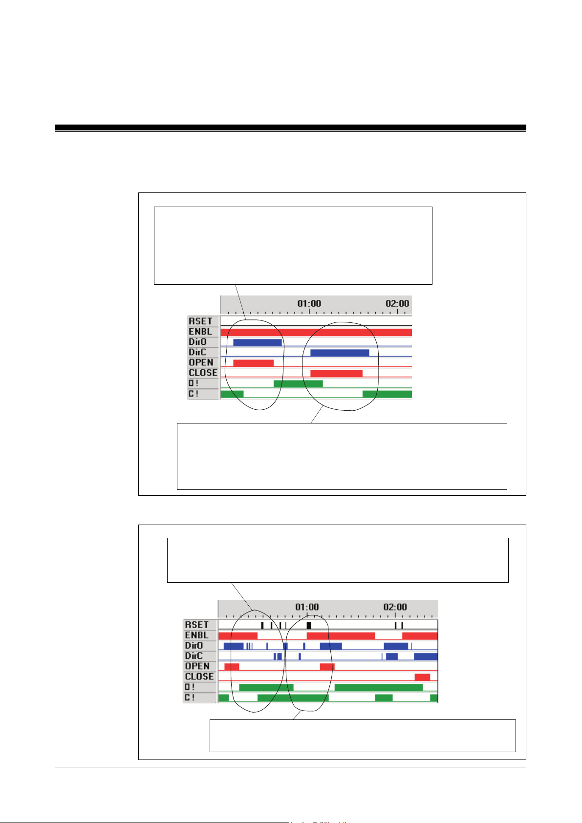
Standard Function Blocks
Timing diagrams
No automatic start after controlled shutdown
OPEN
-output is set when
ENBL
must be "1".
C!
= 1: the flap leaves the CLOSED position.
After the control time, the flap reaches the OPEN position.
The acknowledgment
DirO
The
input can also be reset by the user.
DirO
O!
= 1 resets the
= 1
OPEN
SB153
output.
When
O!
After the control time the flap reaches the CLOSED position.
The acknowledgement
The
Monitoring of end positions
The
present. Despite a reset and
The
DirC
= 1 the
= 1: the flap leaves the OPEN position.
DirC
input can also be reset by the user.
ENBL
signal is cancelled, if both final position acknowledgements are
ENBL
signal is cancelled, if
CLOSE
C!
output sets and the,
= 1 resets the
DirO/DirC
O!/C!
CLOSE
signals, no outputs are reset.
are present simultaneously.
ENBL
output.
must be “1”.
6-44
If the
with
O!/C!
acknowledgements are valid again, they can be reset and
DirO/DirC
the outputs can be activated again.
Modular Block System: Burner Management
Page 89
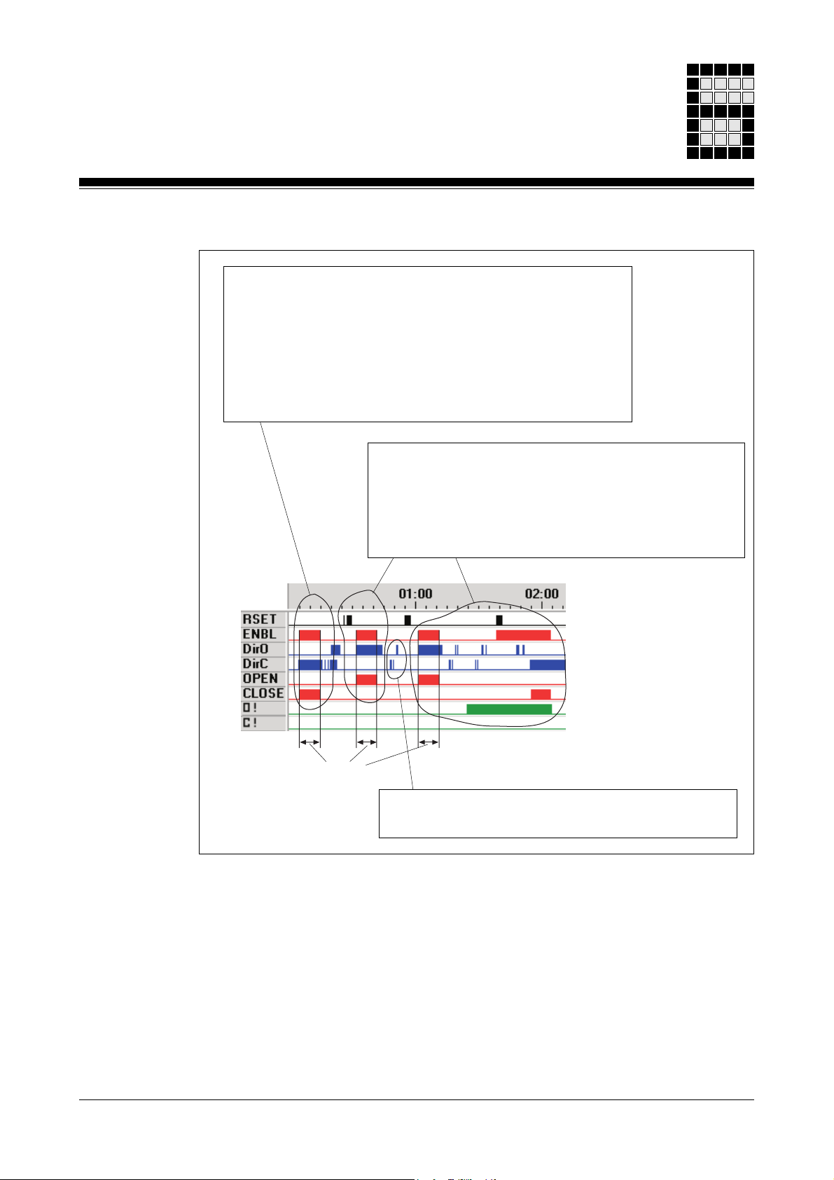
Missing acknowledgement
Behaviour of the flaps in the case of missing or unrequested
end position acknowledgements (single attempt).
The
OPEN
with the
is present, i.e. a fault is registered.
The
OPEN
ENBL
via parameters.
or
CLOSE
ENBL
output, if a “1” signal at the
or
CLOSE
output after the position monitoring time, which is set
output is activated once only, together
DirC
or
DirO
input
output is reset at the same time as the
If the control time monitoring has responded once, a new
control command
RSET
pulse.
If the control time has been exceeded and, subsequently,
a required acknowledgement issued, this must still be
reset before further control commands are handled.
OPEN/CLOSE
can be issued after a
Modular Block System: Burner Management
Control time
The short signals at the inputs are spurious signals.
They are to be expected and will not trigger a fault.
6-45
Page 90

Standard Function Blocks
Multiple drive commands
Repeated drive commands,
although the final position has
already been reached.
No drive commands with invalid input
signals (both inputs “1”)
ENBL
output is reset.
SB153
Spurious fault signal reset
The outputs will be active again only after an
enable reset and a new control command edge.
After a fault signal (
OPEN/CLOSE
at the
DirO/DirC
output is set when there is a 0-1 edge
input and
ENBL
= 0) the corresponding
RSET
pulse.
6-46
Modular Block System: Burner Management
Page 91

Test to ensure safe monitoring time
A new 0-1 edge at the
not reset the control time monitoring.
There are no new pulses for the monitoring
time.
DirO/DirC
input does
Modular Block System: Burner Management
6-47
Page 92

Standard Function Blocks
SB154: Control and position monitoring of valves
Block header
Input parameters
•
SSNR
SB154
VALVE
B - SSNR
X - Pos1
X - Pos2
X - Dir1
X - Dir2
W - T_V
Z- T
X - RSET
ENBL - X
VAV - X
: Safety subroutine number
Permitted value range: 1 ... 200
Format: Byte-constants KB001 ... KB200
(further information about the
SSNR
can be found in the
sections “Administration data blocks DB015, DB016 and
DB017” and “Input Parameter
SSNR
” in chapter 5).
Value of DW0000/DB015 = 0: no error present
6-48
•
Pos1
•
Pos2
•
Dir1
•
Dir2
•
T_V
: Limit switch (N/O contact “start position reached?”)
Pos1
= 1: valve in the “start position”
Pos1
= 0: valve not in the “start position”
: Limit switch (N/O contact “operating position reached?”)
Pos2
= 1: valve in “operating position”
Pos2
= 0: valve not in the “operating position”
: Drive direction
positive edge from
Dir1
: valve will take up the start position
: Drive direction
positive edge from
Dir2
: valve will take up the operating
position
: Switch time for a change in position
Permitted value range: 1 ... 32767,
multiplying the value with the fixed time base of 50 ms gives a
time range from 50 ms ... 27.3 min.
Modular Block System: Burner Management
Page 93

•T: Timer which measures the time
•
RSET
Output parameters
•
ENBL
•
VAV
Function
• Monitoring valve status (open/closed), the direction of a change in
position and the reaction time to a change in position
• Change in valve position after a request (start position, operating
position)
• The contact bounce time due to a change in position is one cycle.
: Reset button (N/O)
: Enable flag bit
ENBL
= 1: this function is fault-free
(refer also to the Programming guidelines)
: Driving the valve
VAV
= 0: bring the valve to its start position
VAV
= 1: bring the valve to its operating position
T_V
Error messages
Any fault that is detected will be stored statically in the corresponding error
data word (SSNR) of DB015 (1st data block).
• Error messages in DB 015
- Bit 00: Status of the contact
Pos1
does not correspond with the
previous drive direction.
Remedy: Check the contact and the switch time
the error in the start position (
operated,
Dir2
= 0) .
- Bit 01: Status of the contact
Pos2
Pos1
operated,
does not correspond with the
T_V
Pos2
and reset
not
previous drive direction.
Remedy: Check the contact and switch time
error in the start position (
Dir2
= 0).
Pos1
operated,
T_V
Pos2
and reset the
not operated
- Bit 02: Switch time for a change in position has been exceeded
Remedy: Check the switch time
reset the error in the start position (
operated,
Dir2
= 0).
T_V
for the contact(s) and the
Pos1
operated,
Pos2
not
Modular Block System: Burner Management
6-49
Page 94

Standard Function Blocks
SB154
- Bit 03:
- Bit 04: Feasibility check: neither limit switch operated
- Bit 05: Feasibility check: both limit switches operated
- Bit 06: Reset button not operated
- Bit 07: Valve start position is missing
• Error messages on the CPU-display
- E 001: Parameter errors
Dir1
and
Dir2
driven simultaneously
Remedy: Only drive in one direction and reset the error in the
start position (
Remedy: Check contacts and reset the error in the start position
(
Pos1
Remedy: Check contacts and reset the error in the start position
(
Pos1
Remedy: Press reset button
Remedy: Check contacts and reset the error in the start position
(
Pos1
The
SSNR
“Administration data blocks DB015, DB016 and DB017” in
chapter 5).
operated,
operated,
operated,
SSNR
is stated in DB015/DW0000 (refer also to the section
Pos1
does not lie within the limits 1 ... 200. The incorrect
operated,
Pos2
Pos2
Pos2
Pos2
not operated,
not operated,
not operated,
not operated,
Dir2
Dir2
Dir2
= 0).
= 0).
= 0).
Dir2
= 0).
Blocks required
6-50
- E007: Invalid time value for
• DB002: Will be made available when the configurator is called up
• DB015: Administration data block
DB015 must consist of its total length of 1024 data words and
have Read/Write status (refer also to the section “Administration data blocks DB015, DB016 and DB017” in chapter 5).
• OB101: To call up SB154
• SB152: BR_START for the error reaction
• SB154: VALVE
• SB255: To call up the operating system
T_V
Modular Block System: Burner Management
Page 95

Programming guidelines
•
ENBL
The enable
before the global input
input
CHAI
decision to use
ENBL
of SB154 must be supplied to the AND-operation
ERR
or to the AND-operation before the global
of SB152 “Burner: Start and operator elements”. The
ERR
or
CHAI
depends on the user and the respective
standards regarding error reaction.
ERR
: If an error is present, a controlled shutdown occurs when
AuSt
= 1 with restart.
CHAI
: If an error is present, a safety shutdown occurs.
A programming example can be found in Chapter 8 under “Managing
enables”.
•
Dir1
and
Dir2
Driving one flap: the drive must be driven in one direction only i.e.
and
Dir2
must not be driven simultaneously.
Dir1
Modular Block System: Burner Management
6-51
Page 96
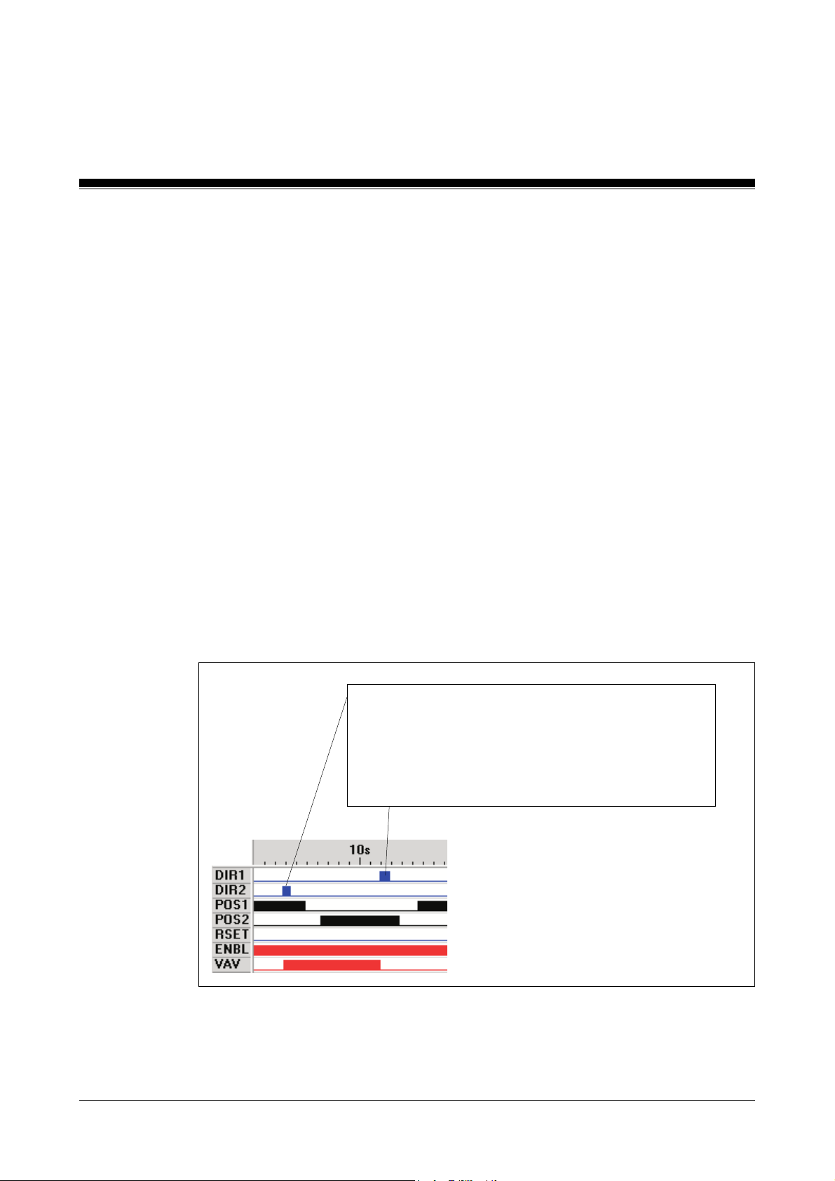
Standard Function Blocks
Timing diagrams
Valve closed without power
It is established which valve position is active on de-energising.
An inverted operating mode can be achieved by changing inputs
Dir2
, but the block's function mode remains unchanged.
Dir1
= 1 drives the block and the
state can, depending on the type of the valve, be the closed or the open
valve position. It is the responsibility of the user to take the type of valve
into consideration and make changes accordingly.
To avoid any misunderstanding, the illustrations and descriptions for the
I/Os in the following function diagrams are defined as such:
VAV
output to a safe state. This safe
SB154
Dir1
and
• Dir1
• Dir2
• Pos1
• Pos2
• VAV
= 1: drive command for the valve to close
= 1: drive command for the valve to open
= 1: acknowledgement feedback: valve closed
= 1: acknowledgement feedback: valve open
= 1: valve open
A pulse at Dir2 sets the VAV output, and the valve
opens.
A pulse at the Dir1 resets the VAV output, and the valve
closes (closed without power). The acknowledgements
from Pos1/Pos2 follow the OPEN/CLOSE commands,
but are delayed.
6-52
Modular Block System: Burner Management
Page 97
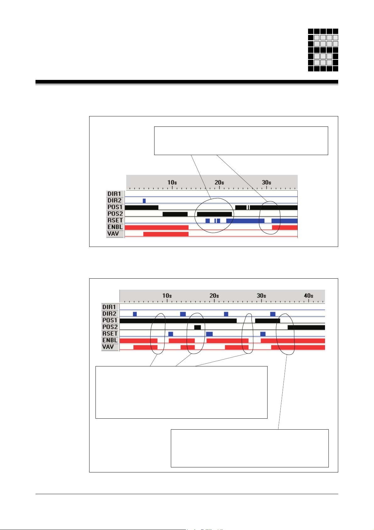
Reset spurious acknowledgements
After a fault lock-out due to an incorrect acknowledgement,
a reset can only occur (with a positive edge at
valve is closed (
Spurious acknowledgement as valve opens
Pos1
=1).
RSET
), if the
The valve positions OPEN/CLOSE are polled to the feedback
inputs
The inputs are polled for validity and the control time
OPEN →CLOSE and CLOSE→ OPEN is monitored. If
faults occur, the
closed immediately and additionally
Modular Block System: Burner Management
Pos1
and
Pos2
.
VAV
output, together with the valve are
ENBL
= 0 is set.
If the “1”-Signal remains off for a time shorter than the
block's set time, the
Only after a “1” signal is off for a longer period will the
ENBL
output be reset.
ENBL
output is not set to "0".
6-53
Page 98
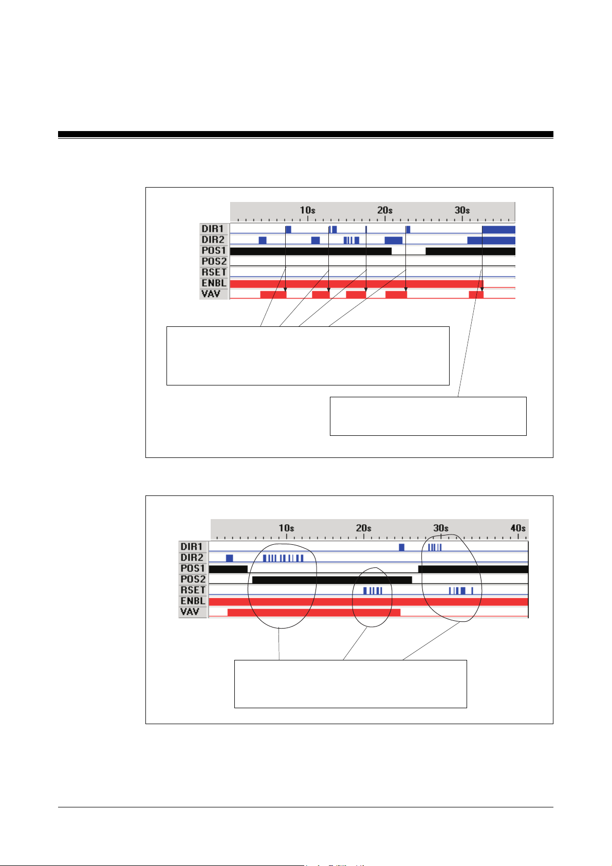
Standard Function Blocks
SImultaneous OPEN and CLOSE commands
A “close valve” command at the Dir1 input resets the VAV
output immediately. The present state of the
acknowledgements at Pos1 and Pos2 has no influence on
the function.
SB154
With simultaneous OPEN/CLOSE
commands, the VAV output is reset.
Multiple recurring OPEN and CLOSE commands
Although the selected state has been achieved,
multiple OPEN/CLOSE commands have no
effect on the outputs.
6-54
Modular Block System: Burner Management
Page 99

Notes
Modular Block System: Burner Management
6-55
Page 100

Standard Function Blocks
SB155: Pre-purge
Block header
Input parameters
•
•
•
SSNR
NEXT
COND
SB155
PREPURGE
B - SSNR
X - NEXT
X - COND
ENBL - X
RDY - X
: Safety subroutine number
Permitted value range: 1 ... 200
Format: Byte-constants KB 001 ... KB 200
(further information about the
SSNR
can be found in the
sections “Administration data blocks DB015, DB016 and
DB017” and the “Input Parameter
SSNR
” in chapter 5).
Value of DW0000/DB015 = 0: no error present
:
NEXT
= 1: activate “pre-purge” step
: Limit switch for maximum position of the air damper or monitor
maximum air flow
COND
= 1: Limit switch is operated
Output parameters
•
ENBL
•
RDY
Function
Monitoring the limit switches for the maximum position of the air damper or
the maximum air flow during the pre-purge time.
6-56
: Enable flag bit
ENBL
= 1: this function is fault-free
(refer also to Programming guidelines)
: Ready signal
RDY
= 1: “Pre-purge” is active
Modular Block System: Burner Management
 Loading...