

Pilz 20 748-03, PSS SB CPU, PSS SB 3006 DP-S, PSS SB 3006 CN-A, PSS SB 3006 IBS-S Operating Manual
...Page 1

Programmable Safety Systems
PSS-Range
PSS SB ACTIVE JUNCTION BASIS
Operating Manual
Item No. 20 748-03
Page 2

2 Operating Manual: PSS SB ACTIVE JUNCTION BASIS
Contents
Function description 3
Intended use 5
Safety 6
EMCD 6
ESD 6
Warranty and liability 6
Safety guidelines 6
Disposal 6
Bus structure with PSS SB ACTIVE JUNCTION BASIS 7
Rules for incorporation 7
Rules for bus termination 7
Determining the bus cable runs and transmission rate 8
SafetyBUS p interfaces 9
SafetyBUS p main branch 9
SafetyBUS p sub branches 9
Installation 10
Supply voltage 11
Insulation voltage test 11
Connection 12
Connecting the supply voltage 12
Earthing 12
Main branch 12
Sub branches 12
Display elements 14
Faults 14
Technical details 15
Page 3
3
Operating Manual: PSS SB ACTIVE JUNCTION BASIS
Function description
The PSS SB ACTIVE JUNCTION BASIS is a component part of the Pilz Active
Junction. An Active Junction consists of a base unit (PSS SB ACTIVE
JUNCTION BASIS) and up to two expansion modules (PSS SB ACTIVE
JUNCTION EXPANSION).
An Active Junction operates as an active junction with repeater function and is
designed for use in SafetyBUS p networks. It galvanically isolates up to 6 sub
branches from the SafetyBUS p main branch. The Active Junction can be used to
connect physically remote field devices to the SafetyBUS p main branch. The
field devices may be in either an IP20 or IP67 environment.
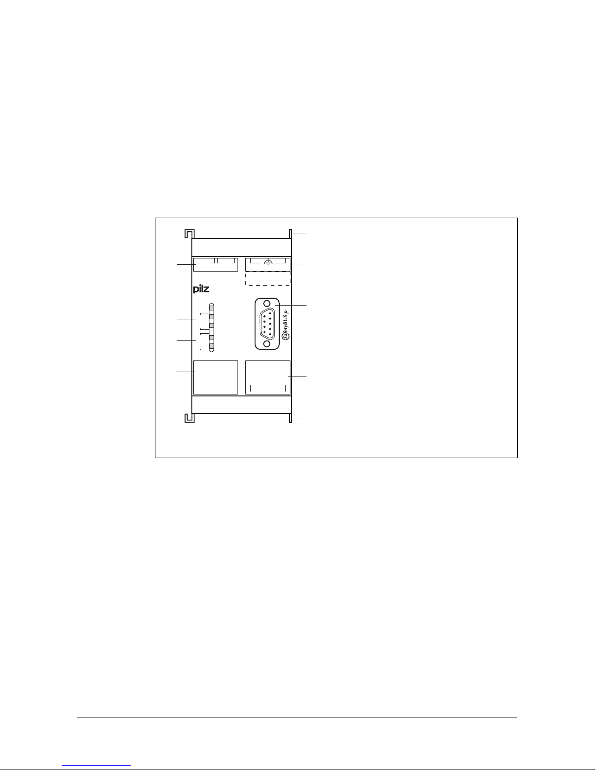
Fig. 1: Elements on the PSS SB ACTIVE JUNCTION BASIS (front view)
If the field devices are in an IP67 environment, the supply voltage for the field
devices can be provided via the Active Junction. In this case, special bus cable
will be required. This is designed for an IP67 environment and contains the lines
for the supply voltage for the field devices as well as the data lines. The
maximum extension of a sub branch is limited by a number of different factors
(number of bus subscribers in the sub branch, transmission rate, current
consumption of the connected field devices etc.).
The base unit PSS SB ACTIVE JUNCTION BASIS is designed for the formation
of two sub branches. If more than two sub branches are required, the expansion
module PSS SB ACTIVE JUNCTION EXPANSION can be used. It is possible to
connect a max. of two expansion modules. Each expansion module can be used
to connect two additional sub branches via the base unit to the SafetyBUS p main
branch.
Power
Traffic
Supply
Traffic
Supply
Sub-Br.Sub-Br.
1
2
ACTIVE JUNCTION
CAN_L
GND
CAN_H
VCC
1... ...4
-X1-
-X2-
1... ...4
-X3-
-X4-
SHIELD
1... ...4
-X5-
Note:
1... ...4
-X0-
24V
0V
BASIS
6
7
8
4
3
2
1
5
5
1: Supply voltage terminal
2: Display elements sub
branch 1
3: Display elements sub
branch 2
4: SafetyBUS p interfaces
(sub branches)
5: Element for attaching an
expansion module
6: Functional earth
connection
7: SafetyBUS p interface
(main branch)
8: Terminals for connecting
the cable screening
Page 4

4 Operating Manual: PSS SB ACTIVE JUNCTION BASIS
I/OD
I/OD
MD
LD
PSS SB ACTIVE JUNCTION BASIS
main branch
sub branch (2)sub branch (1)
IP20
or
IP67
drop line
IP20
1 1
2
3
3 3
4 4 4
5
1 Terminating resistor in
the main branch
(terminator)
2 Terminating resistor for
each sub branch of the
Active Junction
(integrated into the unit)
3 Field devices
4 T-connectors
5 Terminating resistor for
the sub branch
(terminator)
Fig. 2: Bus structure with PSS SB ACTIVE JUNCTION BASIS (principle)
The Active Junction is one of the non-safety-related devices on SafetyBUS p. It
is not assigned a Device Address. Although the Active Junction is not registered
as a bus subscriber, it must be regarded as a bus subscriber when establishing
the transmission rate.
If there is a short circuit in the supply voltage to a sub branch near to the Active
Junction (up to ca. 10 m cable runs), the supply voltage to the sub branch will be
switched off. The “Supply” LED for the relevant sub branch will turn red (see
sections entitled “Display elements” and “Faults”).
If a signal error occurs within a sub branch (permanent dominant signal level),
the sub branch will be ignored. The “Traffic” LED for the relevant sub branch will
turn red (see sections entitled “Display elements” and “Faults”).
Page 5
5
Operating Manual: PSS SB ACTIVE JUNCTION BASIS
Intended use
The PSS SB ACTIVE JUNCTION BASIS is designed for use in SafetyBUS p
networks. It is suitable for connecting physically remote field devices (e.g. light
guards) to the SafetyBUS p main branch. Using the unit allows you to build a star
or tree structure, rather than the linear topology specified for SafetyBUS p.
If the field devices are in an IP67 environment, suitable cable and connection
materials must be used. The information in the guideline: “SafetyBUS p - IP67
Physical Layer Concept”, published by the SafetyBUS p Club International e.V.,
is binding.
Precise details on the PSS SB ACTIVE JUNCTION BASIS are provided in the
“Technical details” section. Use of the device outside the specifications given
here will be deemed as improper use. Any component, technical or electrical
modifications will be deemed as improper use.
Use of the PSS SB ACTIVE JUNCTION BASIS outside the areas described in
this manual will be deemed as improper use. Intended use includes following the
information in this documentation.
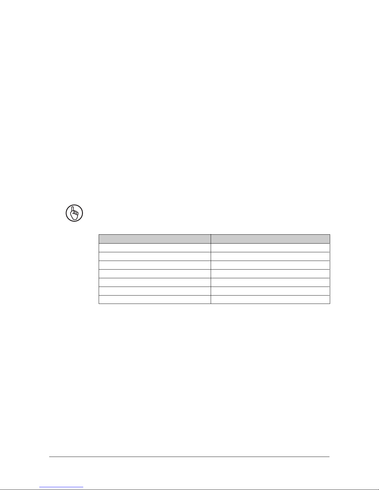
NOTICE
SafetyBUS p subscribers in the following table only support the PSS SB ACTIVE
JUNCTION BASIS from the stated version number onwards:
Table 1
From version
3.0
2.0
2.0
2.0
1.7
2.0
2.0
SafetyBus p module
PSS SB CPU
PSS SB 3006 CN-A
PSS SB 3006 DP-S
PSS SB 3006 IBS-S
PSS SB DI8O8
PSS SB DI16
PSS SB Router1
Page 6

6 Operating Manual: PSS SB ACTIVE JUNCTION BASIS
Safety
The PSS SB ACTIVE JUNCTION BASIS is not a safety-related device.
EMCD
The device is designed for use in an industrial environment. Interference may
occur if used within a domestic environment.
ESD
CAUTION!
Electrostatic discharge can damage components on the device. Ensure against
discharge before touching the device, e.g. by touching an earthed, conductive
surface or by wearing an earthed armband.
Warranty and liability
All claims to warranty and liability will be rendered invalid if:
• The system was used contrary to the purpose for which it is intended
• Damage can be attributed to not having followed the guidelines in the
documentation
• Operating personnel are not suitably qualified.
• The housing was opened
• Any type of modification has been made (e.g. exchanging components on the
PCB boards, soldering work etc.)
Safety guidelines
The information and requirements stipulated in the “SafetyBUS p Installation
Manual” are valid when using the PSS SB ACTIVE JUNCTION BASIS (see
SafetyBUS p System Manual). Failure to comply with these stipulations will
render all warranty and liability claims invalid.
The guidelines in the “SafetyBUS p - IP67 Physical Layer Concept” of the
SafetyBUS p Club International e. V. must also be met.
Disposal
The device must be disposed of properly when it reaches the end of its service
life.
Page 7

7
Operating Manual: PSS SB ACTIVE JUNCTION BASIS
Bus structure with PSS SB ACTIVE JUNCTION BASIS
Rules for incorporation
The Active Junction (base unit and expansion module) is transparent for all
telegrams on the main branch and sub branches. If a signal error occurs within a
sub branch (permanent dominant signal level), the sub branch will be ignored.
Please note the following rules:
• The physical arrangement of the Active Junction on the main branch can be
freely selected. However, bear in mind that run time delays on the signals must
be considered when using an Active Junction. These run time delays can be
expressed as constant virtual cable runs (see section entitled “Determining the
bus cable runs and transmission rate”).
• Using the Active Junction allows you to build a star or tree structure, rather than
the linear topology specified for SafetyBUS p. This reduces the effective
electrical cable runs (no return line needed).
• The relationship of the cable runs to the transmission rate should be
maintained.
• Where possible, plan to use only complete I/O-Groups in a sub branch. This
increases the availability if an error occurs.
Rules for bus termination
Each branch (main branch and sub branches) must be fitted with terminating
resistors.
• The signal lines (CAN_L and CAN_H) on the first and last bus subscribers on
the main branch should be fitted with terminating resistors (120 Ohm).
• The Active Junction is the first bus subscriber on a sub branch. The device has
an integral terminating resistor for each sub branch. The signal lines (CAN_L
and CAN_H) on the last bus subscriber on each sub branch should therefore
be fitted with a terminating resistor (120 Ohm). If necessary use special IP67
terminators.
Page 8

8 Operating Manual: PSS SB ACTIVE JUNCTION BASIS
Determining the bus cable runs and transmission rate
NOTICE
Please read the information in chapter "Designing a SafetyBUS p network" of the
"SafetyBUS p Installation Manual".
If you are using Active Junction please also note:
• Examine every connection combination between the first and last bus
subscriber across all branches (see Fig. 3)
• If the line under examination contains Active Junctions, account for them with
the virtual cable runs as shown in Table 2:
Number of
Active Junctions
1
2
Virtual cable runs
(total)
50 m
100 m
90 m
Cable runs l
Distance
between
adjacent Active Junctions
in the main branch
---
l
Distance
< 10 m
l
Distance
≥ 10 m
MD
LD
I/OD
I/OD
I/OD I/OD
main line
l
Distance
Active Junctions
I/OD I/OD
main branch
l
Distance
l
Distance
Fig. 3: Active Junction arrangement (example)
Table 2
INFORMATION
If possible place all Active Junctions on the main branch (see Fig. 4). This will
guarantee that a maximum of 2 Active Junctions with virtual cable runs will impact
on the main line.
Page 9

9
Operating Manual: PSS SB ACTIVE JUNCTION BASIS
SafetyBUS p interfaces
SafetyBUS p main branch
Connection to the SafetyBUS p main branch is via a male 9-pin D-Sub connector.
Fig. 4: Configuration of the interface to the SafetyBUS p main branch
SafetyBUS p sub branches
Connection to the SafetyBUS p sub branches is via 4-pin screw connectors.
1: n.c.
2: CAN_L (brown)
3: CAN_GND (white)
4: n.c.
5: CAN_SHLD
6: n.c.
7: CAN_H (green)
8: Supply voltage for fibre-optic couplers
from Pilz
9: n.c.
n.c. = not connected
1
9
5
6
Male 9-pin D-Sub connector
9-pin
1234
X1
1234
X2
Fig. 5: Configuration of the interface to the SafetyBUS p sub branches
4-pin screw connectors
(X1/X2)
1: CAN_L (brown)
2: GND (white)
(CAN_GND and VCC_GND)
3: CAN_H (green)
4: VCC (red)
(carried supply voltage 24 V)
Page 10

10 Operating Manual: PSS SB ACTIVE JUNCTION BASIS
75 (2.95")
94 (3.70")
121 (4.76")
45
(1.77")
87 (3.42")
49,2
(1.94")
5
(0.196")
Installation
INFORMATION
Please refer also to the chapter entitled “Installation and Assembly” in the
“SafetyBUS p Installation Manual”.
The PSS SB ACTIVE JUNCTION BASIS is enclosed in a 45 mm P99 housing,
suitable for DIN rail mounting.
• The device should be installed in a control cabinet with a protection type of at
least IP54.
• There are two notches on the back of the unit for DIN rail attachment.
• If you are installing the unit on to a vertical DIN rail, ensure that it is mounted
securely by using a retaining bracket or an end angle.
Fig. 6: Dimensions
Page 11

11
Operating Manual: PSS SB ACTIVE JUNCTION BASIS
Supply voltage
For details of the power supply please refer to the “Technical details” section.
Remember to take into account that the power supply experiences a brief inrush
current (ca. 2 A above current consumption) due to input capacitance.
CAUTION!
• The tolerance on the supply voltage is +25 % or -3 % maximum. Safe operation
cannot be guaranteed outside this range.
• The supply voltage at the field devices must not drop below 20.4 V, otherwise
safe operation cannot be guaranteed.
• Overvoltage or interference voltage can damage or even destroy the electronics
on the device. If this occurs, the affected I/O-Groups will switch to a STOP
condition and all the outputs in the affected I/O-Groups will be switched off. You
should therefore take note of the relevant EMC measures.
• The supply voltage to a sub branch can take a max. 3 A load.
WARNING!
Safe electrical isolation must be ensured for the external 24 V supplies. Failure to
do so could result in electric shock. Power supplies must conform to EN 60742,
9/95 (DIN VDE 0551) or EN 50178, 10/97.
To achieve the lowest possible residual ripple, we recommend that you install a
three-phase bridge rectifier or regulated supply.
Insulation voltage test
Pilz bus subscribers are connected to functional earth via protection elements
on the voltage supply.
Insulation voltage tests are only possible with voltages up to ca. 42 V.
Page 12

12 Operating Manual: PSS SB ACTIVE JUNCTION BASIS
Connection
Connecting the supply voltage
• Connect the 24 V on the power supply to terminal contact 1/2 on terminal block
X0.
• Connect the 0 V on the power supply to terminal contact 3/4 on terminal block
X0.
NOTICE
If the Active Junction is being used to separate sections of the plant, each Active
Junction should be fed through a separate power supply. This will stop a short
circuit in the supply to one plant section affecting the other plant sections.
Earthing
NOTICE
Ensure that the cable screening is connected throughout in each branch. Ensure
the connection for the IN/OUT bus cable is made correctly in each bus
connector.
Please read the information in chapter "Installation and Assembly" of the
"SafetyBUS p Installation Manual".
Main branch
• Connect the cable screening with low impedance to the screen bar or earth bar;
this only needs to be done once for the whole main branch (Fig 8).
• Please refer to the information in the chapter entitled “Installation and
Assembly” in the “SafetyBUS p Installation Manual”.
Sub branches
• Connect each sub branch cable screen to one of the connections on the two
terminal blocks X3/X4 (SHIELD) on the base unit. X3/X4 is connected internally
to X5.
• Connect the X5 terminal block connections (
) on the base unit with low
impedance to the screen bar or earth bar (Fig. 8).
• Follow the guidelines in the “SafetyBUS p - IP67 Physical Layer Concept”
published by the SafetyBUS p Club International e.V.
Page 13

13
Operating Manual: PSS SB ACTIVE JUNCTION BASIS
Fig. 7: Earthing
Legend, Fig. 8:
➀ Cable screening
➁ Galvanic isolation
➂ Base unit PSS SB ACTIVE JUNCTION BASIS
➃ Field device
➄ Screen bar/earth bar
Functional earth
X0
X3 X4
X5
X1 X2
MD
LD
I/OD
I/OD
I/OD
2
3
sub branch (1)
sub branch (2)
X0
X3 X4
X5
X1 X2
2
3
main branch
4
4
4
4
24 V
0 V
5
24 V
0 V
sub branch (1)
sub branch (2)
Page 14

Display elements
Table 3
Faults
If a unit is defective or there is a wiring error, all the outputs in the affected I/OGroup are switched off and the I/O-Group switches to a STOP condition. An error
telegram is then sent to SafetyBUS p and the error is entered in the error buffer
of the controlling PSS.
An error message appears on the display of the controlling PSS. The error stack
display in the programming device and the display elements on the PSS SB
ACTIVE JUNCTION BASIS or PSS SB ACTIVE JUNCTION EXPANSION can be
used to locate the error.
LED
POWER
sub branch 1
sub branch 2
Signal
Lights green
Flickers green
Lights red
Lights green
Lights red
Flickers green
Lights red
Lights green
Lights red
Key
Supply voltage present (screw connector
X0)
Data traffic in
sub branch 1
Signal error in sub branch 1
(permanent dominant signal level)
Supply voltage present in sub branch 1
(screw connector X1)
Short circuit in supply voltage sub branch 1
Data traffic in
sub branch 2
Signal error in sub branch 2
(permanent dominant signal level)
Supply voltage present in sub branch 2
(screw connector X2)
Short circuit in supply voltage sub branch 2
Traffic
Supply
Traffic
Supply
Page 15

Technical details
Electrical data
Supply voltage
Tolerance range
Current consumption
Galvanic isolation
Connection
Sub branches
Virtual cable runs of an Active Junction
SafetyBUS p
Transmission rate
Cable runs
Transmission type
Mechanical data
Max. cross section of external conductors
Torque setting for connection terminals
Dimensions (H x W x D)
Weight
Environmental data
Protection type (EN 60529, 09/00)
Mounting position
Ambient temperature
(EN 60068-2-14, 11/99)
Storage temperature
(EN 60068-2-1/-2, 07/94, 03/93)
Climatic suitability
(DIN IEC 68-2-3, 12/86)
Condensation
Vibration (EN 60068-2-6, 04/95)
Shock (EN 60068-2-27, 03/93)
EMC
24 VDC
23.4 ... 30 VDC including residual ripple of
max. ± 1.2 V
120 mA plus load currents from the
sub branches (max. 6 A) and load currents for
fibre-optic couplers
(max. 25 mA per fibre-optic coupler)
Yes (optocoupler), between the
SafetyBUS p
®
main branch and the
sub branches
SafetyBUS
®
:
Male 9-pin D-Sub connector
Supply and sub branches:
4-pin screw connector
Max. 3 A load current per sub branch,
electronic short circuit protection,
integral terminating resistor (120 Ohm) per sub
branch
50 m
Max. 500 kBit/s
Max. 3500 m
Differential two-wire cable
1 x 2.5 mm2 or 2 x 1.5 mm
2
Single-core or multi-core with
crimp connectors
1.2 Nm (screws)
94 x 49.2 x 126 mm
250 g
IP20
Any
0 ... +60 °C
-25 ... +70 °C
Max. 93 % r.h.
Not permitted
Frequency range: 10 ... 150 Hz
Amplitude: 0.075 mm, max. 1g
30g, 11 ms
EN 61000-6-2, 03/00
EN 55011, 05/00
Page 16

...
www
www.pilz.com
+49 711 3409-444
Pilz GmbH & Co. KG
Sichere Automation
Felix-Wankel-Straße 2
73760 Ostfildern, Germany
Telephone: +49 711 3409-0
Telefax: +49 711 3409-133
E-Mail: pilz.gmbh@pilz.de
In many countries we are
represented by our subsidiaries
and sales partners.
Please refer to our Homepage
for further details or contact our
headquarters.
Technical support
20 749-02-06/04 Printed in Germany
 Loading...