

Page 1

Programmable control systems PSS
®
PSS 3075-3 Series
Operating Manual – Item No. 21 071-10
Page 2

All rights to this documentation are reserved by Pilz GmbH & Co. KG. Copies may be made
for internal purposes.
Suggestions and comments for improving this documentation will be gratefully received.
Pilz®, PIT®, PMI®, PNOZ®, Primo®, PSEN®, PSS®, PVIS®, SafetyBUS p®, SafetyEYE®,
SafetyNET p
®
, the spirit of safety® are registered and protected trademarks of
Pilz GmbH & Co. KG in some countries.
Page 3
1Operating Manual: PSS 3075-3 Series
Introduction 1-1
Validity of documentation 1-2
Overview of documentation 1-3
Definition of symbols 1-4
Overview 2-1
Front views 2-4
PSS 3075-3, PSS 3075-3 NR 2-4
PSS 3075-3 DP-S 2-6
PSS SB 3075-3 2-8
PSS SB 3075-3 DP-S 2-10
PSS SB 3075-3 ETH-2, PSS SB 3075-3 ETH-2 SE 2-12
PSS SB 3075-3 CANopen 2-14
PSS SB 3075-3 ETH-2 CANopen 2-16
Safety 3-1
Intended use 3-1
Product modifications 3-2
Categories in accordance with EN 954-1 3-2
Digital inputs (DI2) 3-2
Single-pole outputs (DOS) 3-3
Dual-pole outputs (DOZ) 3-3
Safety guidelines 3-3
Use of qualified personnel 3-4
EMCD 3-4
Warranty and liability 3-4
Disposal 3-4
Contents
Page 4
Contents
2 Operating Manual: PSS 3075-3 Series
Function Description 4-1
CPU 4-1
Interfaces 4-1
CPU interfaces 4-1
SafetyBUS p interface 4-1
Interfaces for standard bus systems 4-1
Inputs 4-2
Digital inputs (DI2) 4-2
Alarm inputs (DIF) 4-2
Outputs 4-3
Single-pole outputs (DOT/DOS) 4-3
Dual-pole outputs (DOZ) 4-7
Configuration coding 4-8
Installation 5-1
General requirements 5-1
Installing the safety system 5-1
Installing the safety system PSS 3075-3, PSS 3075-3 NR 5-2
Installing the safety system PSS 3075-3 DP-S,
PSS SB 3075-3, PSS SB 3075-3 ETH-2 and
PSS SB 3075-3 ETH-2 SE 5-3
Installing the safety system PSS SB 3075-3 DP-S,
PSS SB 3075-3 CANopen and PSS SB 3075-3 ETH-2 CANopen 5-4
Installing the safety system in a control cabinet 5-5
Supply Voltage 6-1
General requirements 6-1
Notes on wiring 6-3
Page 5
3Operating Manual: PSS 3075-3 Series
Wiring the Inputs and Outputs 7-1
Configuration of the terminals and connector description 7-1
Notes on wiring 7-2
Digital inputs (DI2) 7-4
Example: Single-channel, failsafe input device, without test pulse 7-6
Example: Dual-channel, failsafe input devices, without test pulses 7-8
Example: Single-channel, failsafe input device, with test pulse 7-10
Example: Dual-channel, failsafe input device, with test pulse 7-12
Alarm inputs (DIF) 7-14
Example: Alarm test 7-16
Single-pole outputs (DOS) 7-18
Dual-pole outputs (DOZ) 7-20
Interfaces 8-1
General requirements 8-1
Programming device interface (“PG”) 8-2
Programming device interface RS 232 8-3
Programming device interface RS 485 8-4
User interface (“USER”) 8-5
User interface RS 232 8-6
User interface RS 485 8-7
SafetyBUS p interface (“SafetyBUS p”) 8-8
Interfaces for standard bus connections 8-8
Operation and Maintenance 9-1
Commissioning 9-1
Faults 9-1
PSS and SafetyBUS p functionality 9-1
Standard bus functionality 9-1
Page 6
Contents
4 Operating Manual: PSS 3075-3 Series
Display elements 9-2
PSS functionality 9-2
SafetyBUS p functionality 9-2
Standard bus functionality 9-2
Changing the battery 9-3
Technical Details 10-1
Derating diagrams 10-6
Accessories 10-7
Appendix 11-1
Address of Safety Network International e.V. 11-1
Changes in the documentation 11-1
Page 7

1-1Operating Manual: PSS 3075-3 Series
This operating manual explains the function and operation of the
programmable safety system, describes the installation and provides
guidelines on how to connect the digital inputs, digital outputs and test
pulse outputs on programmable safety systems from the PSS 3075-3
series. A PSS in the PSS SB 3075-3 series is a 3rd generation
programmable safety system.
Depending on the unit type, an interface is available for connection to the
safety-related bus system SafetyBUS p. The SafetyBUS p interface is
described in this manual.
Different interfaces are available for connection to various non-safetyrelated standard bus systems, depending on the unit type. These
interfaces are described in separate operating manuals.
The necessary operating manuals are supplied with the relevant unit types.
Please refer to the PSS-range manuals, in particular the information and
requirements stated in the “PSS-Range Safety Manual”, “FS System
Description”, “ST System Description” and also the “SafetyBUS p Installation Manual” from the Safety BUS p manual package.
You will need to be conversant with the information in these manuals in
order to fully understand this manual.
This documentation is intended for instruction and should be retained for
future reference.
Introduction
Page 8

Introduction
1-2 Operating Manual: PSS 3075-3 Series
Validity of documentation
This documentation is valid for the following programmable safety systems
from the PSS 3075-3 series:
• PSS 3075-3 from Version 1.0
• PSS 3075-3 DP-S from Version 1.0
• PSS 3075-3 NR from Version 1.0
• PSS SB 3075-3 from Version 1.0
• PSS SB 3075-3 CANopen from Version 3.0
• PSS SB 3075-3 DP-S from Version 1.0
• PSS SB 3075-3 ETH-2 from Version 1.0
• PSS SB 3075-3 ETH-2 CANopen from Version 1.0
• PSS SB 3075-3 ETH-2 SE from Version 1.0
It is valid until new documentation is published. The latest documentation is
always enclosed with the unit.
Page 9

1-3Operating Manual: PSS 3075-3 Series
Overview of documentation
1 Introduction
The introduction is designed to familiarise you with the contents,
structure and specific order of this manual.
2 Overview
This chapter provides information on the most important features of
the programmable safety systems.
3 Safety
This chapter must be read as it contains important information on
safety regulations and intended use.
4 Function Description
This chapter describes the individual components of the
programmable safety systems: CPU, inputs, outputs and test pulse
outputs.
5 Installation
This chapter explains how to install the programmable safety
systems.
6 Supply Voltage
This chapter explains what you need to consider when connecting the
supply voltage.
7 Wiring the Inputs and Outputs
This chapter describes the safety-related wiring of the inputs, outputs
and test pulse outputs.
8 Interfaces
This chapter describes the configuration of the available interfaces.
9 Operation and Maintenance
This chapter explains how to commission the safety systems and
advises on what to do if a fault occurs.
10 Technical Details
11 Appendix
Page 10
Introduction
1-4 Operating Manual: PSS 3075-3 Series
Definition of symbols
Information in this manual that is of particular importance can be identified
as follows:
DANGER!
This warning must be heeded! It warns of a hazardous situation that
poses an immediate threat of serious injury and death and indicates
preventive measures that can be taken.
WARNING!
This warning must be heeded! It warns of a hazardous situation that
could lead to serious injury and death and indicates preventive
measures that can be taken.
CAUTION!
This refers to a hazard that can lead to a less serious or minor injury plus
material damage, and also provides information on preventive measures
that can be taken.
NOTICE
This describes a situation in which the unit(s) could be damaged and also
provides information on preventive measures that can be taken.
INFORMATION
This gives advice on applications and provides information on special
features, as well as highlighting areas within the text that are of particular
importance.
Page 11

2-1Operating Manual: PSS 3075-3 Series
Overview
A PSS from the PSS 3075-3 series is a complete programmable safety
system in a single unit.
The device descriptions provide information on their function.
The description are made up of combinations of letters and numbers.
• The PSS 3075-3 contains:
- Power supply
- CPU
- 48 digital inputs, 6 of which are alarm inputs
- 18 single-pole outputs, 4 of which are test pulse outputs
- 9 dual-pole outputs
- Programming device interface
(combined RS 232/RS 485 interface)
- User interface
(combined RS 232/RS 485 interface)
• In addition to the features on the PSS 3075-3, the PSS SB 3075-3
contains:
- SafetyBUS p-interface
Additional functions
• DP-S
Interface for connection to PROFIBUS-DP
• ETH-2
Interface for connection to Ethernet
• CANopen
Interface for connection to CANopen
• SE
The name "SE“ can be found only on the type label of the PSS (e. g. PSS
SB 3075-3 ETH-2 SE). It is a PSS that is identical to the corresponding
serial device (e. g. PSS SB 3075-3 ETH-2). The PSS however is intended
for use with SafetyEYE and therefore delivered with a preinstalled user
program.
• NR
Safety system without battery
Operation without a battery results in the following restrictions:
- FS section: Remanant data blocks cannot be used.
- ST section: A general reset is performed each time the section
switches from STOP-RUN.
- Each time the PSS is restarted (voltage switched off and then on
again), the system time is reset to zero.
Page 12

Overview
2-2 Operating Manual: PSS 3075-3 Series
For non-safety-related applications, the PSS can be connected to various
standard bus systems (e.g. PROFIBUS-DP). The bus interfaces that are
available will depend on the unit type.
INFORMATION
• The standard bus interfaces are described in separate operating
manuals. The necessary operating manuals are supplied with the relevant unit types.
• Drivers (standard function blocks) from the corresponding Pilz software
package will be required in order to connect to the various standard bus
systems.
Example:
PSS SB 3075-3 ETH-2
Safety systems PSS 3075-3 with SafetyBUS p- and Ethernet interface.
The digital inputs can be used for local emergency stop monitoring, for
example. They are suitable for connecting single or dual-channel input
devices, with or without test pulses. The test pulse outputs are suitable for
testing input devices.
The single or dual-pole outputs can be used to drive valves, for example.
SafetyBUS p enables you to establish a safe decentralised network of
several programmable safety systems and/or to connect decentralised
modules. The PSS can perform the function of a Management, Logic or
Input/Output Device on SafetyBUS p.
Page 13

2-3Operating Manual: PSS 3075-3 Series
Notes
Page 14
Overview
2-4 Operating Manual: PSS 3075-3 Series
Front views
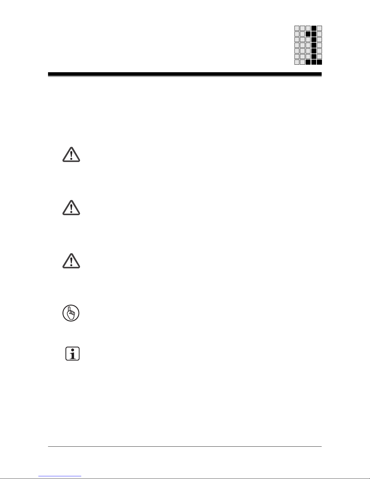
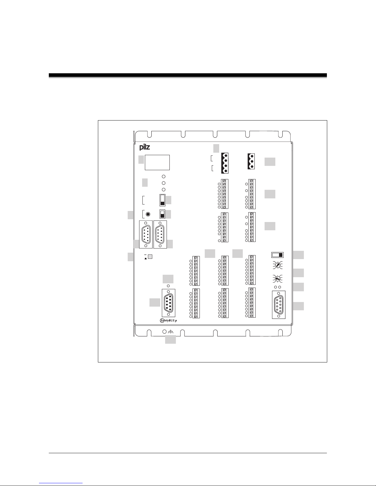
PSS 3075-3, PSS 3075-3 NR
Fig. 2-1: Front view of PSS 3075-3
O -1.19
O +1.19
O -1.20
O +1.20
O - 1.21
O +1.21
O 4.8
O 4.9
O 4.10
1
·
X7
·
3
1
·
·
·
X8
·
·
·
9
1
·
·
·
X9
·
·
·
9
1
·
·
·
X10
·
·
·
9
1
·
·
·
X11
·
·
·
9
X8/X9 PWR
PWR
RUN FS
PG
RUN ST
POWER
RUN
STOP
AUTO PG
SPS
ST
FS
PSS 3075-3
1
·
X0
·
4
USER
F-STACK
0 V
I 0.8
I 0.9
I 0.10
I 0.11
I 0.12
I 0.13
I 0.14
I 0.15
0 V
I 0.0
I 0.1
I 0.2
I 0.3
I 0.4
I 0.5
I 0.6
I 0.7
0 V
I 1.0
I 1.1
I 1.2
I 1.3
I 1.4
I 1.5
I 1.6
I 1.7
0 V
I 1.8
I 1.9
I 3.0
I 3.1
I 3.2
I 3.3
I 3.4
I 3.5
1
·
·
·
X3
·
·
·
9
1
·
·
·
X4
·
·
·
9
1
·
·
·
X5
·
·
·
9
1
·
·
·
X6
·
·
·
9
1
·
·
·
X1
·
·
·
9
1
·
·
·
X2
·
·
·
9
O -2.17
O +2.17
O 2.15
O/T 2.0
O/T 2.1
O/T 2.2
O/T 2.3
O -2.18
O +2.18
RT (USER)
OFF
ON
PSS
X1/X2
O -2.16
O +2.16
O 2.8
O 2.9
O 2.10
O 2.11
O 2.12
O 2.13
O 2.14
O -1.16
O +1.16
O -1.17
O+1.17
O -1.18
O +1.18
O 4.0
O 4.1
O 4.2
0 V
I 0.24
I 0.25
I 0.26
I 0.27
I 0.28
I 0.29
I 0.30
I 0.31
0 V
I 0.16
I 0.17
I 0.18
I 0.19
I 0.20
I 0.21
I 0.22
I 0.23
24 V
0 V
2
4
5
10
12
9
11
11
1
3
6
8
7
PG
24 V
0 V
24 V
0 V
13
10
Page 15

2-5Operating Manual: PSS 3075-3 Series
Key:
1: 4-digit display
2: LEDs for PSS operating mode and supply voltage
3: 3-position switch for selecting the standard section’s operating mode
4: Button for scrolling the error stack
5: 2-position switch for selecting the failsafe section’s operating mode
6: Programming device interface
RS 232 (minimum configuration: TxD, RxD, GND)/RS 485
7: User interface
RS 232/RS 485
8: Pushbutton for switching on and off the RS 485 termination on the
user interface
9: Supply voltage connection (24 VDC) for internal supply of the
safety system and the outputs at X1, X2
10: Digital outputs and test pulse outputs
11: Digital inputs
12: Functional earth connection
13: Supply voltage connection (24 VDC) for outputs at X8, X9
Page 16
Overview
2-6 Operating Manual: PSS 3075-3 Series
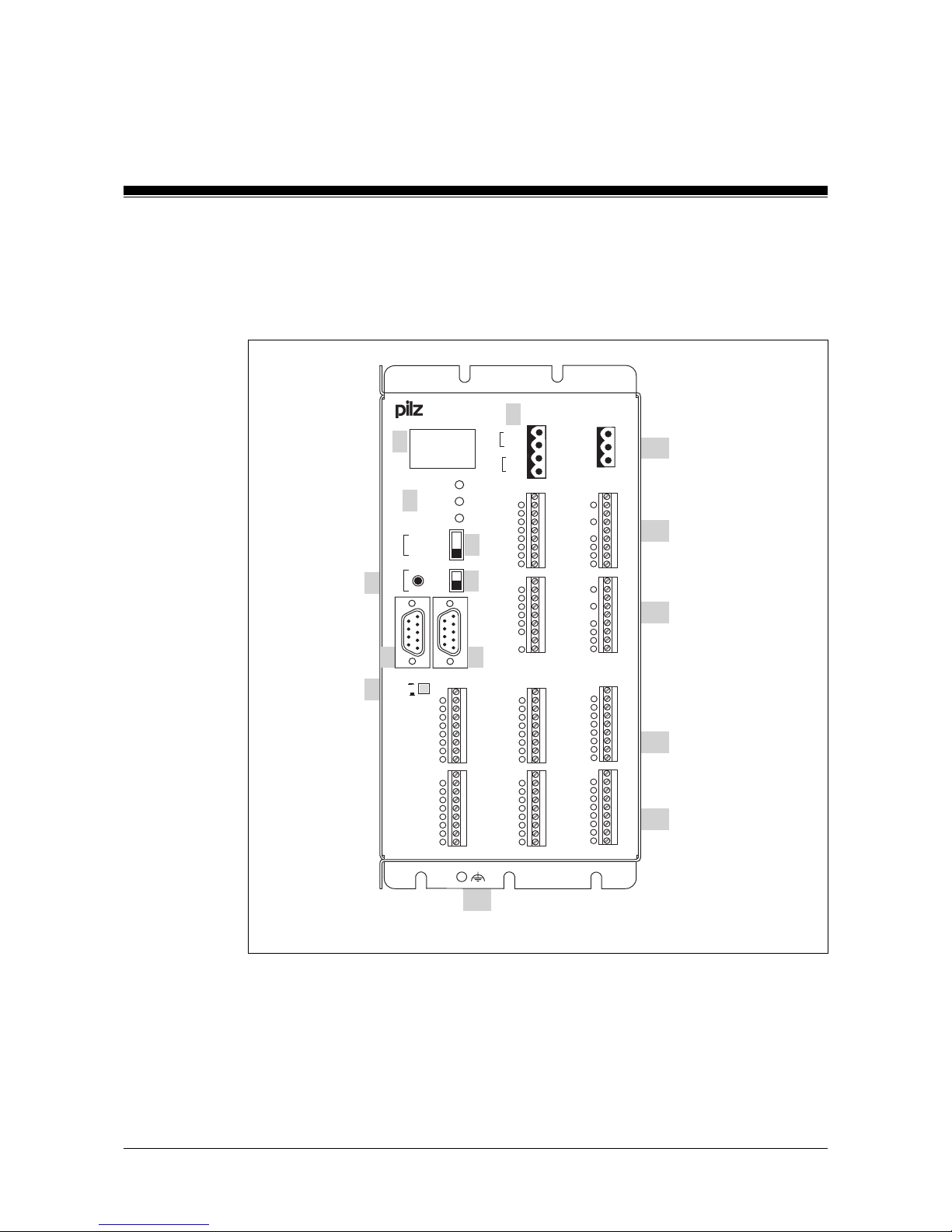
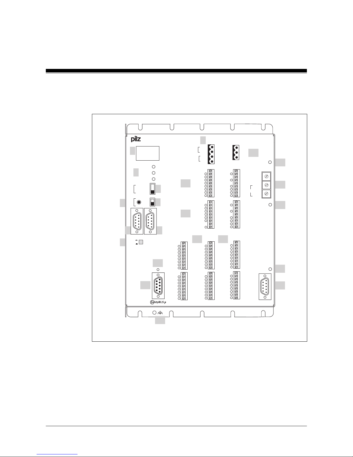
PSS 3075-3 DP-S
Fig. 2-2: Front view of PSS 3075-3 DP-S
O -1.19
O +1.19
O -1.20
O +1.20
O - 1.21
O +1.21
O 4.8
O 4.9
O 4.10
1
·
X7
·
3
1
·
·
·
X8
·
·
·
9
1
·
·
·
X9
·
·
·
9
1
·
·
·
X10
·
·
·
9
1
·
·
·
X11
·
·
·
9
X8/X9 PWR
PWR
RUN FS
PG
RUN ST
POWER
RUN
STOP
AUTO PG
SPS
ST
FS
PSS 3075-3 DP-S
1
·
X0
·
4
USER
F-STACK
0 V
I 0.8
I 0.9
I 0.10
I 0.11
I 0.12
I 0.13
I 0.14
I 0.15
0 V
I 0.0
I 0.1
I 0.2
I 0.3
I 0.4
I 0.5
I 0.6
I 0.7
0 V
I 1.0
I 1.1
I 1.2
I 1.3
I 1.4
I 1.5
I 1.6
I 1.7
0 V
I 1.8
I 1.9
I 3.0
I 3.1
I 3.2
I 3.3
I 3.4
I 3.5
1
·
·
·
X3
·
·
·
9
1
·
·
·
X4
·
·
·
9
1
·
·
·
X5
·
·
·
9
1
·
·
·
X6
·
·
·
9
1
·
·
·
X1
·
·
·
9
1
·
·
·
X2
·
·
·
9
O -2.17
O +2.17
O 2.15
O/T 2.0
O/T 2.1
O/T 2.2
O/T 2.3
O -2.18
O +2.18
RT (USER)
OFF
ON
PSS
X1/X2
O -2.16
O +2.16
O 2.8
O 2.9
O 2.10
O 2.11
O 2.12
O 2.13
O 2.14
O -1.16
O +1.16
O -1.17
O+1.17
O -1.18
O +1.18
O 4.0
O 4.1
O 4.2
0 V
I 0.24
I 0.25
I 0.26
I 0.27
I 0.28
I 0.29
I 0.30
I 0.31
0 V
I 0.16
I 0.17
I 0.18
I 0.19
I 0.20
I 0.21
I 0.22
I 0.23
24 V
0 V
2
4
5
10
12
9
11
11
1
3
6
8
7
PG
24 V
0 V
24 V
0 V
13
10
x10
x1
PROFIBUS-DP
+100
+0
RUNFAULT
6
7
8
9
4
3
2
1
5
0
6
7
8
9
4
3
2
1
5
0
ADDRESS
15
14
16
17
Page 17

2-7Operating Manual: PSS 3075-3 Series
Key:
1: 4-digit display
2: LEDs for PSS operating mode and supply voltage
3: 3-position switch for selecting the standard section’s operating mode
4: Button for scrolling the error stack
5: 2-position switch for selecting the failsafe section’s operating mode
6: Programming device interface
RS 232 (minimum configuration: TxD, RxD, GND)/RS 485
7: User interface
RS 232/RS 485
8: Pushbutton for switching on and off the RS 485 termination on the
user interface
9: Supply voltage connection (24 VDC) for internal supply of the
safety system and the outputs at X1, X2
10: Digital outputs and test pulse outputs
11: Digital inputs
12: Functional earth connection
13: Supply voltage connection (24 VDC) for outputs at X8, X9
14: 2-position switch for selecting the station address
(PROFIBUS-DP)
15: Rotary switch for setting the station address
(PROFIBUS-DP)
16: LED for status of PROFIBUS-DP
17: PROFIBUS-DP interface
INFORMATION
Please refer also to the manual: “PROFIBUS-DP for Compact 3rd Generation PSS”.
Page 18
Overview
2-8 Operating Manual: PSS 3075-3 Series
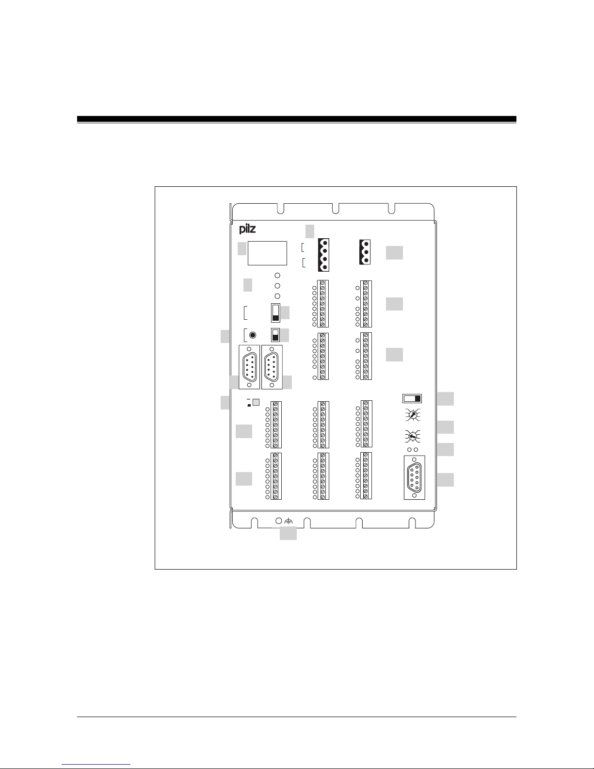
PSS SB 3075-3
Fig. 2-3: Front view of PSS SB 3075-3
RUN FS
PG
RUN ST
POWER
RUN
STOP
AUTO PG
SPS
ST
FS
PSS SB 3075-3
USER
F-STACK
0 V
I 1.8
I 1.9
I 3.0
I 3.1
I 3.2
I 3.3
I 3.4
I 3.5
0 V
I 1.0
I 1.1
I 1.2
I 1.3
I 1.4
I 1.5
I 1.6
I 1.7
1
·
·
·
X5
·
·
·
9
1
·
·
·
X6
·
·
·
9
RT (USER)
OFF
ON
PSS
X1/X2
0 V
I 0.24
I 0.25
I 0.26
I 0.27
I 0.28
I 0.29
I 0.30
I 0.31
2
4
5
12
11
11
1
3
6
8
7
PG
O -1.19
O +1.19
O -1.20
O +1.20
O - 1.21
O +1.21
O 4.8
O 4.9
O 4.10
1
·
X7
·
3
1
·
·
·
X8
·
·
·
9
1
·
·
·
X9
·
·
·
9
1
·
·
·
X10
·
·
·
9
1
·
·
·
X11
·
·
·
9
X8/X9 PWR
PWR
1
·
X0
·
4
0 V
I 0.8
I 0.9
I 0.10
I 0.11
I 0.12
I 0.13
I 0.14
I 0.15
0 V
I 0.0
I 0.1
I 0.2
I 0.3
I 0.4
I 0.5
I 0.6
I 0.7
1
·
·
·
X3
·
·
·
9
1
·
·
·
X4
·
·
·
9
1
·
·
·
X1
·
·
·
9
1
·
·
·
X2
·
·
·
9
O -2.17
O +2.17
O 2.15
O/T 2.0
O/T 2.1
O/T 2.2
O/T 2.3
O -2.18
O +2.18
O -2.16
O +2.16
O 2.8
O 2.9
O 2.10
O 2.11
O 2.12
O 2.13
O 2.14
O -1.16
O +1.16
O -1.17
O+1.17
O -1.18
O +1.18
O 4.0
O 4.1
O 4.2
0 V
I 0.16
I 0.17
I 0.18
I 0.19
I 0.20
I 0.21
I 0.22
I 0.23
24 V
0 V
10
9
24 V
0 V
24 V
0 V
13
10
15
14
STATUS SB
Page 19

2-9Operating Manual: PSS 3075-3 Series
Key:
1: 4-digit display
2: LEDs for PSS operating mode and supply voltage
3: 3-position switch for selecting the standard section’s operating mode
4: Button for scrolling the error stack
5: 2-position switch for selecting the failsafe section’s operating mode
6: Programming device interface
RS 232 (minimum configuration: TxD, RxD, GND)/RS 485
7: User interface
RS 232/RS 485
8: Pushbutton for switching on and off the RS 485 termination on the
user interface
9: Supply voltage connection (24 VDC) for internal supply of the
safety system and the outputs at X1, X2
10: Digital outputs and test pulse outputs
11: Digital inputs
12: Functional earth connection
13: Supply voltage connection (24 VDC) for outputs at X8, X9
14: LED for status of SafetyBUS p
15: SafetyBUS p interface
Page 20
Overview
2-10 Operating Manual: PSS 3075-3 Series
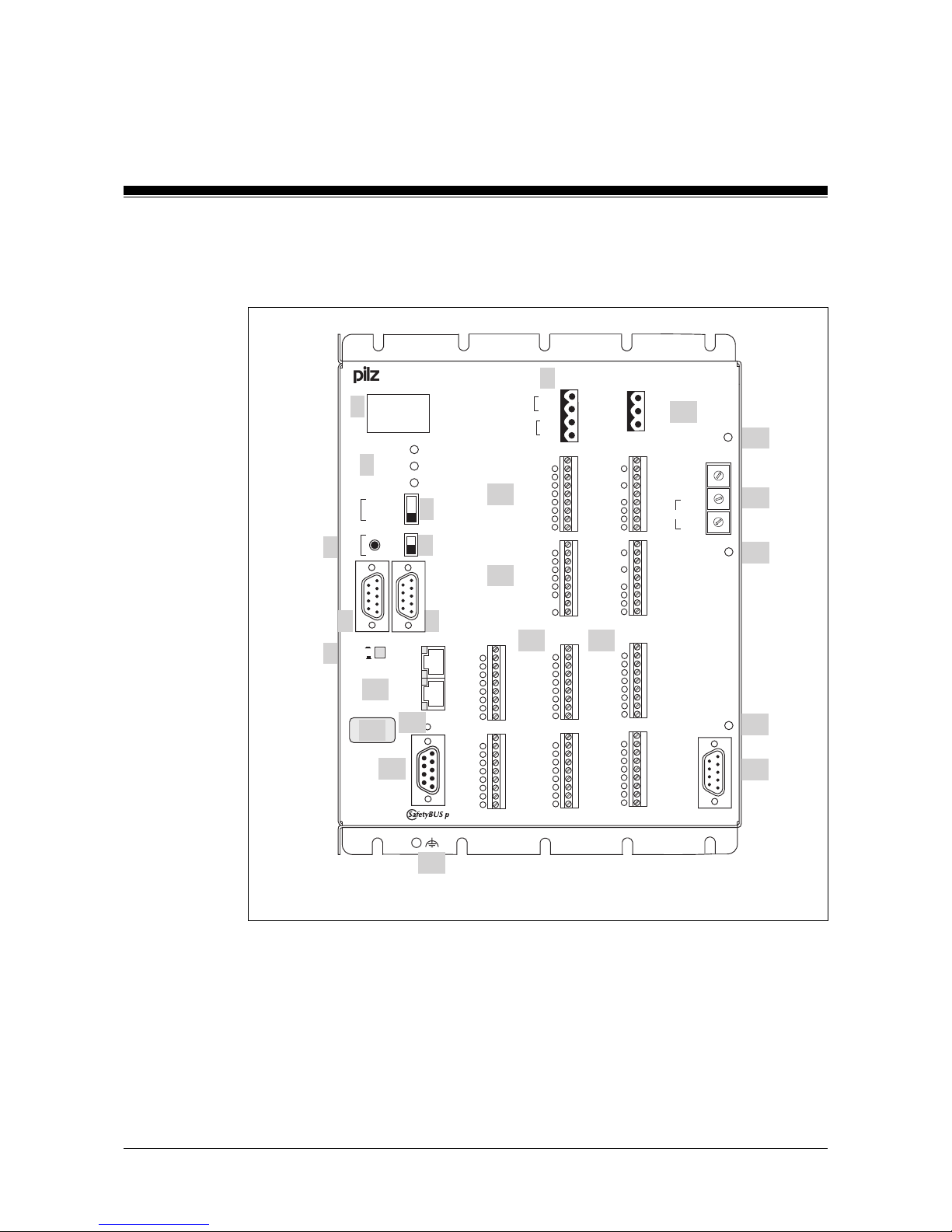
PSS SB 3075-3 DP-S
Fig. 2-4: Front view of PSS SB 3075-3 DP-S
RUN FS
PG
RUN ST
POWER
RUN
STOP
AUTO PG
SPS
ST
FS
PSS SB 3075-3 DP-S
USER
F-STACK
0 V
I 1.8
I 1.9
I 3.0
I 3.1
I 3.2
I 3.3
I 3.4
I 3.5
0 V
I 1.0
I 1.1
I 1.2
I 1.3
I 1.4
I 1.5
I 1.6
I 1.7
1
·
·
·
X5
·
·
·
9
1
·
·
·
X6
·
·
·
9
RT (USER)
OFF
ON
PSS
X1/X2
0 V
I 0.24
I 0.25
I 0.26
I 0.27
I 0.28
I 0.29
I 0.30
I 0.31
2
4
5
12
11
11
1
3
6
8
7
PG
O -1.19
O +1.19
O -1.20
O +1.20
O - 1.21
O +1.21
O 4.8
O 4.9
O 4.10
1
·
X7
·
3
1
·
·
·
X8
·
·
·
9
1
·
·
·
X9
·
·
·
9
1
·
·
·
X10
·
·
·
9
1
·
·
·
X11
·
·
·
9
X8/X9 PWR
PWR
1
·
X0
·
4
0 V
I 0.8
I 0.9
I 0.10
I 0.11
I 0.12
I 0.13
I 0.14
I 0.15
0 V
I 0.0
I 0.1
I 0.2
I 0.3
I 0.4
I 0.5
I 0.6
I 0.7
1
·
·
·
X3
·
·
·
9
1
·
·
·
X4
·
·
·
9
1
·
·
·
X1
·
·
·
9
1
·
·
·
X2
·
·
·
9
O -2.17
O +2.17
O 2.15
O/T 2.0
O/T 2.1
O/T 2.2
O/T 2.3
O -2.18
O +2.18
O -2.16
O +2.16
O 2.8
O 2.9
O 2.10
O 2.11
O 2.12
O 2.13
O 2.14
O -1.16
O +1.16
O -1.17
O+1.17
O -1.18
O +1.18
O 4.0
O 4.1
O 4.2
0 V
I 0.16
I 0.17
I 0.18
I 0.19
I 0.20
I 0.21
I 0.22
I 0.23
24 V
0 V
10
9
24 V
0 V
24 V
0 V
13
10
19
18
STATUS SB
x10
x1
PROFIBUS-DP
+100
+0
RUNFAULT
6
7
8
9
4
3
2
1
5
0
6
7
8
9
4
3
2
1
5
0
ADDRESS
15
14
16
17
Page 21

2-11Operating Manual: PSS 3075-3 Series
Key:
1: 4-digit display
2: LEDs for PSS operating mode and supply voltage
3: 3-position switch for selecting the standard section’s operating mode
4: Button for scrolling the error stack
5: 2-position switch for selecting the failsafe section’s operating mode
6: Programming device interface
RS 232 (minimum configuration: TxD, RxD, GND)/RS 485
7: User interface
RS 232/RS 485
8: Pushbutton for switching on and off the RS 485 termination on the
user interface
9: Supply voltage connection (24 VDC) for internal supply of the
safety system and the outputs at X1, X2
10: Digital outputs and test pulse outputs
11: Digital inputs
12: Functional earth connection
13: Supply voltage connection (24 VDC) for outputs at X8, X9
14: 2-position switch for selecting the station address
(PROFIBUS-DP)
15: Rotary switch for setting the station address
(PROFIBUS-DP)
16: LED for status of PROFIBUS-DP
17: PROFIBUS-DP interface
18: LED for status of SafetyBUS p
19: SafetyBUS p interface
INFORMATION
Please refer also to the manual: “PROFIBUS-DP for Compact 3rd Generation PSS”
Page 22
Overview
2-12 Operating Manual: PSS 3075-3 Series
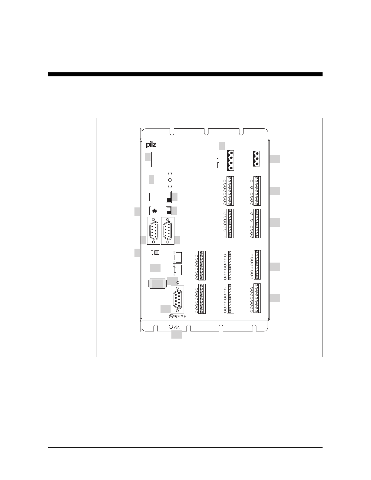
PSS SB 3075-3 ETH-2, PSS SB 3075-3 ETH-2 SE
Fig. 2-5: Front view of PSS SB 3075-3 ETH-2
RUN FS
PG
RUN ST
POWER
RUN
STOP
AUTO PG
SPS
ST
FS
PSS SB 3075-3 ETH-2
USER
F-STACK
0 V
I 1.8
I 1.9
I 3.0
I 3.1
I 3.2
I 3.3
I 3.4
I 3.5
0 V
I 1.0
I 1.1
I 1.2
I 1.3
I 1.4
I 1.5
I 1.6
I 1.7
1
·
·
·
X5
·
·
·
9
1
·
·
·
X6
·
·
·
9
RT (USER)
OFF
ON
PSS
X1/X2
0 V
I 0.24
I 0.25
I 0.26
I 0.27
I 0.28
I 0.29
I 0.30
I 0.31
O -1.19
O +1.19
O -1.20
O +1.20
O - 1.21
O +1.21
O 4.8
O 4.9
O 4.10
1
·
X7
·
3
1
·
·
·
X8
·
·
·
9
1
·
·
·
X9
·
·
·
9
1
·
·
·
X10
·
·
·
9
1
·
·
·
X11
·
·
·
9
X8/X9 PWR
PWR
1
·
X0
·
4
0 V
I 0.8
I 0.9
I 0.10
I 0.11
I 0.12
I 0.13
I 0.14
I 0.15
0 V
I 0.0
I 0.1
I 0.2
I 0.3
I 0.4
I 0.5
I 0.6
I 0.7
1
·
·
·
X3
·
·
·
9
1
·
·
·
X4
·
·
·
9
1
·
·
·
X1
·
·
·
9
1
·
·
·
X2
·
·
·
9
O -2.17
O +2.17
O 2.15
O/T 2.0
O/T 2.1
O/T 2.2
O/T 2.3
O -2.18
O +2.18
O -2.16
O +2.16
O 2.8
O 2.9
O 2.10
O 2.11
O 2.12
O 2.13
O 2.14
O -1.16
O +1.16
O -1.17
O+1.17
O -1.18
O +1.18
O 4.0
O 4.1
O 4.2
0 V
I 0.16
I 0.17
I 0.18
I 0.19
I 0.20
I 0.21
I 0.22
I 0.23
2
4
5
12
11
11
1
3
6
8
7
PG
24 V
0 V
10
9
24 V
0 V
24 V
0 V
13
10
17
16
15
ETHERNET
LINK
10/100
BASE T
TRAFFIC
LINK
TRAFFIC
10/100
BASE T
14
STATUS SB
Page 23

2-13Operating Manual: PSS 3075-3 Series
Key:
1: 4-digit display
2: LEDs for PSS operating mode and supply voltage
3: 3-position switch for selecting the standard section’s operating mode
4: Button for scrolling the error stack
5: 2-position switch for selecting the failsafe section’s operating mode
6: Programming device interface
RS 232 (minimum configuration: TxD, RxD, GND)/RS 485
7: User interface
RS 232/RS 485
8: Pushbutton for switching on and off the RS 485 termination on the
user interface
9: Supply voltage connection (24 VDC) for internal supply of the
safety system and the outputs at X1, X2
10: Digital outputs and test pulse outputs
11: Digital inputs
12: Functional earth connection
13: Supply voltage connection (24 VDC) for outputs at X8, X9
14: Labelling strip for Ethernet address
15: ETH-2 interface with connection to ETHERNET via integrated switch
(2 free ports); LEDs on each port for
- Status of network connection (LINK)
- Status of data traffic (TRAFFIC)
16: LED for status of SafetyBUS p
17: SafetyBUS p interface
INFORMATION
Please refer also to the manual: “ETH-2 for Compact 3rd Generation PSS”.
Page 24
Overview
2-14 Operating Manual: PSS 3075-3 Series
PSS SB 3075-3 CANopen
Fig. 2-6: Front view of PSS SB 3075-3 CANopen
RUN FS
PG
RUN ST
POWER
RUN
STOP
AUTO PG
SPS
ST
FS
PSS SB 3075-3 CANopen
USER
F-STACK
0 V
I 1.8
I 1.9
I 3.0
I 3.1
I 3.2
I 3.3
I 3.4
I 3.5
0 V
I 1.0
I 1.1
I 1.2
I 1.3
I 1.4
I 1.5
I 1.6
I 1.7
1
·
·
·
X5
·
·
·
9
1
·
·
·
X6
·
·
·
9
RT (USER)
OFF
ON
PSS
X1/X2
0 V
I 0.24
I 0.25
I 0.26
I 0.27
I 0.28
I 0.29
I 0.30
I 0.31
O -1.19
O +1.19
O -1.20
O +1.20
O - 1.21
O +1.21
O 4.8
O 4.9
O 4.10
1
·
X7
·
3
1
·
·
·
X8
·
·
·
9
1
·
·
·
X9
·
·
·
9
1
·
·
·
X10
·
·
·
9
1
·
·
·
X11
·
·
·
9
X8/X9 PWR
PWR
1
·
X0
·
4
0 V
I 0.8
I 0.9
I 0.10
I 0.11
I 0.12
I 0.13
I 0.14
I 0.15
0 V
I 0.0
I 0.1
I 0.2
I 0.3
I 0.4
I 0.5
I 0.6
I 0.7
1
·
·
·
X3
·
·
·
9
1
·
·
·
X4
·
·
·
9
1
·
·
·
X1
·
·
·
9
1
·
·
·
X2
·
·
·
9
O -2.17
O +2.17
O 2.15
O/T 2.0
O/T 2.1
O/T 2.2
O/T 2.3
O -2.18
O +2.18
O -2.16
O +2.16
O 2.8
O 2.9
O 2.10
O 2.11
O 2.12
O 2.13
O 2.14
O -1.16
O +1.16
O -1.17
O+1.17
O -1.18
O +1.18
O 4.0
O 4.1
O 4.2
0 V
I 0.16
I 0.17
I 0.18
I 0.19
I 0.20
I 0.21
I 0.22
I 0.23
CANopen
CAN ERROR
CAN STATUS
BITRATE
HIGH
LOW
MODUL ID
CPU STATUS
0
8
C
4
E
A
6
2
F
B
3
1
D
9
7
5
0
8
C
4
E
A
6
2
F
B
3
1
D
9
7
5
0
8
C
4
E
A
6
2
F
B
3
1
D
9
7
5
2
4
5
12
11
11
1
3
6
8
7
PG
24 V
0 V
10
9
24 V
0 V
24 V
0 V
13
10
20
19
15
14
16
17
18
STATUS SB
Page 25

2-15Operating Manual: PSS 3075-3 Series
Key:
1: 4-digit display
2: LEDs for PSS operating mode and supply voltage
3: 3-position switch for selecting the standard section’s operating mode
4: Button for scrolling the error stack
5: 2-position switch for selecting the failsafe section’s operating mode
6: Programming device interface
RS 232 (minimum configuration: TxD, RxD, GND)/RS 485
7: User interface
RS 232/RS 485
8: Pushbutton for switching on and off the RS 485 termination on the
user interface
9: Supply voltage connection (24 VDC) for internal supply of the
safety system and the outputs at X1, X2
10: Digital outputs and test pulse outputs
11: Digital inputs
12: Functional earth connection
13: Supply voltage connection (24 VDC) for outputs at X8, X9
14: LED for data transfer errors
15: Rotary switch for setting the node number Bit rate (1st rotary switch)
and the Node-ID (2nd rotary switch)
16: LED for CPU status
17: LED for the CANopen data cable status
18: CANopen interface
19: LED for status of SafetyBUS p
20: SafetyBUS p interface
INFORMATION
Please refer also to the manual: “CANopen for Compact 3rd Generation
PSS”.
Page 26
Overview
2-16 Operating Manual: PSS 3075-3 Series
PSS SB 3075-3 ETH-2 CANopen
Fig. 2-7: Front view of PSS SB 3075-3 ETH-2 CANopen
RUN FS
PG
RUN ST
POWER
RUN
STOP
AUTO PG
SPS
ST
FS
PSS SB 3075-3 ETH-2 CANopen
USER
F-STACK
0 V
I 1.8
I 1.9
I 3.0
I 3.1
I 3.2
I 3.3
I 3.4
I 3.5
0 V
I 1.0
I 1.1
I 1.2
I 1.3
I 1.4
I 1.5
I 1.6
I 1.7
1
·
·
·
X5
·
·
·
9
1
·
·
·
X6
·
·
·
9
RT (USER)
OFF
ON
PSS
X1/X2
0 V
I 0.24
I 0.25
I 0.26
I 0.27
I 0.28
I 0.29
I 0.30
I 0.31
O -1.19
O +1.19
O -1.20
O +1.20
O - 1.21
O +1.21
O 4.8
O 4.9
O 4.10
1
·
X7
·
3
1
·
·
·
X8
·
·
·
9
1
·
·
·
X9
·
·
·
9
1
·
·
·
X10
·
·
·
9
1
·
·
·
X11
·
·
·
9
X8/X9 PWR
PWR
1
·
X0
·
4
0 V
I 0.8
I 0.9
I 0.10
I 0.11
I 0.12
I 0.13
I 0.14
I 0.15
0 V
I 0.0
I 0.1
I 0.2
I 0.3
I 0.4
I 0.5
I 0.6
I 0.7
1
·
·
·
X3
·
·
·
9
1
·
·
·
X4
·
·
·
9
1
·
·
·
X1
·
·
·
9
1
·
·
·
X2
·
·
·
9
O -2.17
O +2.17
O 2.15
O/T 2.0
O/T 2.1
O/T 2.2
O/T 2.3
O -2.18
O +2.18
O -2.16
O +2.16
O 2.8
O 2.9
O 2.10
O 2.11
O 2.12
O 2.13
O 2.14
O -1.16
O +1.16
O -1.17
O+1.17
O -1.18
O +1.18
O 4.0
O 4.1
O 4.2
0 V
I 0.16
I 0.17
I 0.18
I 0.19
I 0.20
I 0.21
I 0.22
I 0.23
CANopen
CAN ERROR
CAN STATUS
BITRATE
HIGH
LOW
MODUL ID
CPU STATUS
0
8
C
4
E
A
6
2
F
B
3
1
D
9
7
5
0
8
C
4
E
A
6
2
F
B
3
1
D
9
7
5
0
8
C
4
E
A
6
2
F
B
3
1
D
9
7
5
21
2
4
5
12
11
11
1
3
6
8
7
PG
24 V
0 V
10
9
24 V
0 V
24 V
0 V
13
10
20
15
14
16
17
18
22
ETHERNET
LINK
10/100
BASE T
TRAFFIC
LINK
TRAFFIC
10/100
BASE T
STATUS SB
19
Page 27

2-17Operating Manual: PSS 3075-3 Series
Key:
1: 4-digit display
2: LEDs for PSS operating mode and supply voltage
3: 3-position switch for selecting the standard section’s operating mode
4: Button for scrolling the error stack
5: 2-position switch for selecting the failsafe section’s operating mode
6: Programming device interface
RS 232 (minimum configuration: TxD, RxD, GND)/RS 485
7: User interface
RS 232/RS 485
8: Pushbutton for switching on and off the RS 485 termination on the
user interface
9: Supply voltage connection (24 VDC) for internal supply of the
safety system and the outputs at X1, X2
10: Digital outputs and test pulse outputs
11: Digital inputs
12: Functional earth connection
13: Supply voltage connection (24 VDC) for outputs at X8, X9
14: LED for data transfer errors
15: Rotary switch for setting the node number Bit rate (1st rotary switch)
and the Node-ID (2nd rotary switch)
16: LED for CPU status
17: LED for the CANopen data cable status
18: CANopen interface
19: Labelling strip for Ethernet address
20: SafetyBUS p interface
21: LED for status of SafetyBUS p
22: ETH-2 interface with connection to ETHERNET via integrated switch
(2 free ports); LEDs on each port for
- Status of network connection (LINK)
- Status of data traffic (TRAFFIC)
INFORMATION
Please refer also to the manual: “CANopen for Compact 3rd Generation
PSS” and “ETH-2 for Compact 3rd Generation PSS”.
Page 28

Overview
2-18 Operating Manual: PSS 3075-3 Series
Notes
Page 29
3-1Operating Manual: PSS 3075-3 Series
Safety
Intended use
Programmable safety systems from the PSS 3075-3 series are intended
for use as follows:
• Safety-related applications
in the PSS failsafe section
• Non-safety-related applications in the
PSS standard section
INFORMATION
The following system software is required in order to program the safety
systems:
• PSS WIN-PRO from Version 1.1.2 for
- PSS 3075-3
- PSS 3075-3 DP-S
- PSS SB 3075-3 DP-S
• PSS WIN-PRO from Version 1.3.1 for
- PSS SB 3075-3
- PSS SB 3075-3 ETH-2
- PSS SB 3075-3 ETH-2 SE
• PSS WIN-PRO from Version 1.5.2 for
- PSS SB 3075-3 CANopen
• PSS WIN-PRO from Version 1.8.0 for
- PSS SB 3075-3 ETH-2 CANopen
• PSS WIN-PRO from Version 1.8.2 for
- PSS 3075-3 NR
INFORMATION
Drivers (standard function blocks) from the corresponding Pilz software
package will be required in order to connect to the various standard bus
systems:
• ST-SB-DP-S: Driver for PROFIBUS-DP Slave
• ST SB CANopen: Driver for CANopen
For the standard bus interface ETH-2, the Ethernet Configurator is
available as part of the PSS WIN-PRO system software from Version 1.3.1.
Page 30

Safety
3-2 Operating Manual: PSS 3075-3 Series
The following is deemed improper use:
• Any component, technical or electrical modification to the safety system
• Use of the safety system outside the areas described in this manual
• Use of the safety system outside the documented technical details (see
chapter entitled “Technical Details”).
Intended use includes making the installation EMC-compliant. Please
observe the guidelines given in this manual and in the “Safety Manual” for
the PSS-range. The “Safety Manual” also includes check lists designed to
help you with the safety-related planning, construction and operation of a
plant.
Product modifications
Details of the changes made to a unit from one version to the next are
described in the “Product Modifications” file. This file can be found on the
“Documentation PSS-Range/SafetyBUS p” CD or on the Internet
(www.pilz.com) with the unit’s documentation.
Categories in accordance with EN 954-1
WARNING!
Please note: To achieve the corresponding category or requirement class,
the whole system including all safety-related components (parts, devices,
user program etc.) must be included in the assessment. For this reason,
Pilz cannot accept liability for the correct classification into a category or
requirement class.
Digital inputs (DI2)
Depending on the application area and its respective regulations, the
inputs may be used without test pulses for applications up to category 3,
in accordance with EN 954-1. The possibility of a short circuit occurring in
the external wiring between different inputs or against L+ must be
eliminated through appropriate wiring.
Page 31

3-3Operating Manual: PSS 3075-3 Series
For category 4 applications, shorts between the input contacts must be
detected. This can be achieved through the use of test pulses on the PSS
or, depending on the type of input device, through a feasibility test or
through detection of shorts across the contacts on the input device (e.g.
light barrier) (for connection examples please see Chapter 7, “Wiring the
Inputs and Outputs”).
Single-pole outputs (DOS)
An additional shutdown route means that the outputs on the PSS can be
used in single-channel operation for applications up to category 3 in
accordance with EN 954-1 (03/97). Please note that in this case a
feedback circuit must be used.
To achieve category 4, two actuators must be connected in series to two
different outputs.
Dual-pole outputs (DOZ)
The dual-pole outputs can be used for applications up to
category 4 in accordance with EN 954-1 (03/97).
Safety guidelines
Failure to keep to these guidelines will render all warranty and liability
claims invalid:
• All health and safety / accident prevention regulations for the particular
area of application must be observed.
• Before using the unit it is necessary to perform a safety assessment in
accordance with the Machinery Directive 98/37/EC.
Page 32

Safety
3-4 Operating Manual: PSS 3075-3 Series
Use of qualified personnel
The safety system may only be assembled, installed, programmed,
commissioned, operated, maintained and decomissioned by qualified
personnel. Qualified personnel are people who, because they are:
• Qualified electrical engineers and
• Have received training from qualified electrical engineers,
are suitably experienced to operate devices, systems, plant and machinery
in accordance with the general standards and guidelines for safety
technology.
EMCD
The safety system is designed for use in an industrial environment.
Interference may occur if used within a domestic environment.
Warranty and liability
All claims to warranty and liability will be rendered invalid if:
• The safety system was used contrary to the purpose for which it was
intended
• Damage can be attributed to not having followed the guidelines in the
manual
• Operating personnel are not suitably qualified.
• Any type of modification has been made (e.g. exchanging components
on the PCB boards, soldering work etc.).
Disposal
The programmable safety system must be disposed of properly when it
reaches the end of its service life.
Page 33

Operating Manual: PSS 3075-3 Series
4-1
Function Description
CPU
The CPU controls the outputs, reads the inputs and processes / stores the
user program and variable data. The failsafe section is designed to be
multi-channel, i.e. different CPUs process the user program independently.
A four-digit display and several LEDs provide information on the status of
the safety system and indicate any errors.
Interfaces
CPU interfaces
The CPU of each programmable safety system in the PSS 3075-3 series
provides the following interfaces:
• Programming device interface
Combined RS 232 interface (minimum configuration: TxD, RxD, GND)/
RS 485
• User interface
Combined RS 232/RS 485 interface (termination is selectable)
For further information please refer to the “System Manual for the
PSS-Range”.
SafetyBUS p interface
The programmable safety system from the PSS 3075-3 series may have a
SafetyBUS p interface, depending on the unit type. For further information
on SafetyBUS p, please refer to the “System Manual for SafetyBUS p”.
Interfaces for standard bus systems
Different interfaces are available for connection to various standard bus
systems, depending on the unit type. The standard bus interfaces are
described in separate operating manuals. The necessary operating
manuals are supplied with the relevant unit types.
Page 34

Function Description
4-2 Operating Manual: PSS 3075-3 Series
Inputs
Programmable safety systems from the PSS 3075-3 series have 48 digital
inputs (DI2), 6 of which can be configured as alarm inputs (DIF).
The digital input signals must show a “High” (“1” signal) of 24 VDC (+15 ...
+30 VDC) or a “Low” (“0” signal) of 0 VDC (-3 ... +5 VDC).
LEDs are used as status indicators. An LED lights up as soon as a “1”
signal is present at the input. Inputs have input filters and are galvanically
isolated from the control electronics through optocouplers.
Digital inputs (DI2)
Internal diagnostic circuitry checks the function of the inputs, including the
optocoupler. If an error occurs, the PSS will switch to a STOP condition,
switch off the outputs and send a message to the CPU-display.
Alarm inputs (DIF)
The CPU program cycle will be interrupted if there is a signal change at an
alarm input. Depending on the configuration, rising, falling or both types of
pulse edges may trigger an alarm. Only those alarms triggered by a signal
change from “1” to “0” are safety-related. As soon as an alarm signal
(signal change) occurs at one of the alarm inputs, the signal is sent to the
CPU through a hardware connection. The CPU determines which input
triggered the alarm and, if the pulse edge is configured as active, calls up
the relevant alarm OB. The user can program whatever measures are
necessary into this alarm OB (see “FS System Description”).
Internal diagnostic circuitry checks the function of the inputs. If an error
occurs, the PSS will switch to a STOP condition, switch off the outputs and
send a message to the CPU-display. The input filter and optocoupler can
be tested using test pulses.
Page 35

Operating Manual: PSS 3075-3 Series
4-3
INFORMATION
For further information on alarm processing please refer to the “FS System
Description” from the “PSS System Manual for the compact/modular PSS”
Outputs
Programmable safety systems from the PSS 3075-3 series have 18 singlepole outputs (DOS) and 9 dual-pole outputs (DOZ). 4 of the single-pole
outputs can be configured as test pulse outputs (DOT).
INFORMATION
On programmable safety systems from the PSS 3075-3 series, only
outputs O1.16 ... O1.21, O/T2.0 ... O/T2.3, O2.8 ... O2.18, O4.0 ... O4.2
and O4.8 ... O4.10 are available at the terminals.
Please note: Unwired outputs O1.22 ... O1.31, O2.4 ... O2.7, O2.19 ...
O2.31, O4.3 ... O4.7 and O4.11 ... O4.15 cannot be configured in the
system software.
Single-pole outputs (DOT/DOS)
Programmable safety systems from the PSS 3075-3 series have 18 singlepole outputs with a load capacity of 1.5 A.
The 4 outputs O/T2.0 ... O/T2.3 can be configured together as test pulse
outputs.
Outputs configured as test pulse outputs supply the test pulses to check
the input filters and optocouplers on the inputs. The CPU checks whether
the inputs connected to a test pulse output can detect a signal change.
INFORMATION
Please note that unused test pulses must remain unconnected.
Page 36

Function Description
4-4 Operating Manual: PSS 3075-3 Series
Once the CPU sends a “1” signal via the system bus, the PSS will supply
24 VDC to the relevant output. The status of the outputs is displayed
through LEDs, which light as soon as a “1” signal (24 VDC) is present at
the output.
Internal diagnostic circuitry tests the function of the outputs. During each
cycle, the CPU compares the actual status of the outputs with the process
image of the outputs. Outputs that are switched on will be switched off
during each self test in order to check that the output transistors can be
switched. Outputs that are switched off will be switched on during each
self test in order to check the monitoring circuit. A test will also be carried
out to check for shorts between the outputs of a sub-slot (short circuits are
detected only when the outputs are switched on). If an error occurs, the
PSS will switch to a STOP condition, switch off the outputs and send a
message to the CPU-display.
If a plant is particularly sensitive to the pulses from the power-up test on
outputs that are switched off, individual outputs or all single-pole outputs
can be excluded from testing. This is achieved using operating system call
SB255, function 2 (see overleaf).
If you deactivate the output power-up test, please make sure you observe
the following guidelines:
NOTICE
On an output that is switched off, follow the instructions below: At a noncritical point in the program, switch the output on and then off again for
one PSS cycle. If the output does not switch correctly, the error will be
detected and registered by the operating system. To also detect shorts
between outputs that are switched off, outputs must be switched on at an
offset of one cycle.
NOTICE
To detect whether an output has been excluded from the output test
incorrectly, or whether the output test that the user has programmed is
effective, an error simulation must be carried out on each safety-related
output during commissioning. To do this, the affected output must be
switched off (output’s diode not lit up). If you then generate a short circuit
between the output and 0 V, the desired error reaction should occur. In the
worst case, the error reaction should occur within 30 minutes.
Page 37

Operating Manual: PSS 3075-3 Series
4-5
• The output power-up tests are a component part of the system’s self
check. The self check is carried out when voltage is returned, on start up
(transfer from STOP-RUN) and also during operation.
• Operating system call SB255, function 2 in OB120 is required to
deactivate the power-up test on start up. To deactivate the power up-test
during operation, the operating system call must be contained in a block
that is run as part of each cycle. The power-up test will be performed
again as soon as the operating system call is no longer present.
NOTICE
Each time SB255, function 2 is called, data words DW200, DW201 and
DW202 must be written in full to ensure that outputs are not excluded from
the power-up test unintentionally, due to data words being unwittingly
overwritten during the program cycle.
Page 38

Function Description
4-6 Operating Manual: PSS 3075-3 Series
Block
SB255
DB003
DB001
Input
FUNK = 2
DW200
DW201
DW202
Output
ERG = 1
DW200
Key
Deactivate output power-up test in bits
Function performed without error
Incorrect SB255 calls will lead to a STOP
condition
Slot number
on the PSS 3075-3 series: 2 / 4
Masks for outputs 2.00 ... 2.15 / 4.00 ... 4.15
If this is set on a bit belonging to an output, the
power-up test for this output will be deactivated.
For example: 0101
H
-> output 2.0 and 2.8
on the PSS 3075-3 series:
• Outputs 2.8 … 2.15, 4.0 ... 4.2 / 4.8 ...
4.10 can be masked
• Outputs 2.0 … 2.3 can only be masked if they
are not configured as test pulses
• Outputs 2.4 … 2.7, 4.3 ... 4.7 / 4.11 ... 4.15
(outputs not available at the terminals) cannot
be masked, their bits must always equal 0
Masks for outputs 2.16 ... 2.31 / 4.16 ... 4.31
on the PSS 3075-3 series: 0000
H
Outputs 2.16 ... 2.31 / 4.16 ... 4.31 cannot be
masked, their bits must always equal 0.
Fault detection:
0: No error
1: Invalid slot number
2: Slot not occupied
3: Not possible to deactivate the power-up test on
the stated outputs
4: Call of SB255, FUNK = 2 not permitted in alarm
OB
Page 39

Operating Manual: PSS 3075-3 Series
4-7
Dual-pole outputs (DOZ)
9 dual-pole outputs are available.
The load must be connected between the “+” and “-” terminals. When the
CPU sends a “1” signal via the system bus, the PSS supplies 24 VDC to
the relevant output. The status of the outputs is displayed through LEDs,
which light as soon as a “1” signal (24 VDC) is present at the output.
Internal diagnostic circuitry tests the function of the connected outputs. On
outputs that are switched on, the CPU will alternately switch off the “+” and
“-” terminals as part of each cycle. This is to check that the corresponding
output transistors can be switched off and that there is no interruption to
the load. In addition, outputs that are connected but switched off will be
switched on for approx. 100 µs during each self test. If an error occurs, the
PSS will switch to a STOP condition, switch off the outputs and send a
message to the CPU-display.
All outputs are protected against short-circuit, overload and excess
temperature. They can switch both resistive and inductive loads.
Page 40

Function Description
4-8 Operating Manual: PSS 3075-3 Series
Configuration coding
Inputs and outputs are located on a sub-slot, which is allocated a code:
Slot
0
1
2
3
4
Sub-slot
0
1
2
3
4
5
6
7
8
9
Inputs/outputs
I0.00 - I0.15
I0.16 - I0.31
I1.00 - I1.09
O1.16 - O1.21
O2.00 - O2.03
O2.08 - O2.15
O2.16 - O2.18
I3.00 - I3.05
...
O4.00 - O4.02
O4.08 - O4.10
...
Code
C003
H
C003
H
C003
H
C011
H
C017
H
C011
H
D002
H
...
C015
H
...
...
Page 41

5-1Operating Manual: PSS 3075-3 Series
General requirements
Please note the following:
• The safety system should be installed in an enclosure, e.g. control
cabinet, that conforms to the protection class required for the
environment.
• When installing the system in an enclosure such as a control cabinet, the
environmental data for the safety system must be taken into account.
Details can be found in the chapter entitled “Technical Details”.
• Ensure there is sufficient ventilation to prevent heat building up within the
control cabinet. Please note the ambient temperature of 0 ... 60 °C.
• In extreme ambient conditions, additional measures may be required in
order to keep within the prescribed value range.
• Use low interference panel lighting for inside the control cabinet.
• The safety system must be installed in such a way that there is adequate
protection against buttons and switches being operated unintentionally.
CAUTION!
Risk of burns!
Do not touch the metal parts of the housing.
If the safety system is operated at an ambient temperature of more than
45 °C, surface temperatures on the housing may reach more than 80 °C at
full load.
Installing the safety system
There are two options for installing the safety system. Both options are
shown in the following illustrations. Drill M4 holes in the control cabinet’s
mounting plate, as shown in the illustrations (tolerance: +/-0.3 mm/0.012").
Attach the safety system to the mounting plate in your control cabinet,
using washers.
Installation
Page 42

Installation
5-2 Operating Manual: PSS 3075-3 Series
Fig. 5-1:
Installation options for the programmable safety system PSS 3075-3 and
PSS 3075-3 NR
Dimensions stated in mm (")
Installing the safety system PSS 3075-3 and PSS 3075-3 NR
Option A:
Dimensions in mm (") excluding interfaces and operating controls :
H x W x D: 246.4 x 123.6 x 162 (9.70" x 4.87" x 6.38")
Option B:
120
(4.72")
120
(4.72")
21
(0.83")
21
(0.83")
40
(1.57")
17
(0.67")
37
(1.46")
40
(1.57")
40
(1.57")
236,4 (9.31")
236,4 (9.31")
Page 43

5-3Operating Manual: PSS 3075-3 Series
Installing the safety system PSS 3075-3 DP-S, PSS SB 3075-3,
PSS SB 3075-3 ETH-2 and PSS SB 3075-3 ETH-2 SE
Dimensions in mm (") excluding interfaces and operating controls :
H x W x D: 246.4 x 160.2 x 162 (9.70" x 6.31" x 6.38")
Fig. 5-2:
Installation options for the programmable safety system PSS 3075-3 DP-S,
PSS SB 3075-3, PSS SB 3075-3 ETH-2 and PSS SB 3075-3 ETH-2 SE
Dimensions stated in mm (")
Option A:
Option B:
40
(1.57")
40
(1.57")
40
(1.57")
17
(0.67")
21
(0.83")
21
(0.83")
37
(1.46")
40
(1.57")
40
(1.57")
60
(2.36")
60
(2.36")
60
(2.36")
60
(2.36")
236,4 (9.31")
236,4 (9.31")
Page 44

Installation
5-4 Operating Manual: PSS 3075-3 Series
Fig. 5-3:
Installation options for the programmable safety system PSS SB 3075-3 DP-S,
PSS SB 3075-3 CANopen and PSS SB 3075-3 ETH-2 CANopen
Dimensions stated in mm (")
Installing the safety system PSS SB 3075-3 DP-S, PSS SB 3075-3 CANopen and
PSS SB 3075-3 ETH-2 CANopen
Dimensions in mm (") excluding interfaces and operating controls :
H x W x D: 246.4 x 196.8 x 162 (9.70" x 7.58" x 6.38")
40
(1.57")
40
(1.57")
40
(1.57")
17
(0.67")
21
(0.83")
21
(0.83")
37
(1.46")
40
(1.57")
40
(1.57")
60
(2.36")
60
(2.36")
60
(2.36")
60
(2.36")
40
(1.57")
40
(1.57")
236,4 (9.31")
236,4 (9.31")
Option A:
Option B:
Page 45

5-5Operating Manual: PSS 3075-3 Series
Installing the safety system in a control cabinet
Fig. 5-4: Installing safety systems from the PSS 3075-3 series in a control cabinet
(example: PSS 3075-3), dimensions stated in mm (")
13 mm
(0.51")
No
minimum distance
from control cabinet
Distance from top
min. 130 mm (5.12")
Power section
min. 60 mm (2.36")
Cable duct max. (W x H):
100 x 50 mm (3.94" x 1.97")
220.4 mm
(8.68")
13 mm
(0.51")
Functional earth
connection
123 mm
(4.84")
O -1.19
O +1.19
O -1.20
O +1.20
O - 1.21
O +1.21
O 4.8
O 4.9
O 4.10
1
·
X7
·
3
1
·
·
·
X8
·
·
·
9
1
·
·
·
X9
·
·
·
9
1
·
·
·
X10
·
·
·
9
1
·
·
·
X11
·
·
·
9
X8/X9 PWR
PWR
RUN FS
PG
RUN ST
POWER
RUN
STOP
AUTO PG
SPS
ST
FS
PSS 3075-3
1
·
X0
·
4
USER
F-STACK
0 V
I 0.8
I 0.9
I 0.10
I 0.11
I 0.12
I 0.13
I 0.14
I 0.15
0 V
I 0.0
I 0.1
I 0.2
I 0.3
I 0.4
I 0.5
I 0.6
I 0.7
0 V
I 1.0
I 1.1
I 1.2
I 1.3
I 1.4
I 1.5
I 1.6
I 1.7
0 V
I 1.8
I 1.9
I 3.0
I 3.1
I 3.2
I 3.3
I 3.4
I 3.5
1
·
·
·
X3
·
·
·
9
1
·
·
·
X4
·
·
·
9
1
·
·
·
X5
·
·
·
9
1
·
·
·
X6
·
·
·
9
1
·
·
·
X1
·
·
·
9
1
·
·
·
X2
·
·
·
9
O -2.17
O +2.17
O 2.15
O/T 2.0
O/T 2.1
O/T 2.2
O/T 2.3
O -2.18
O +2.18
RT (USER)
OFF
ON
PSS
X1/X2
O -2.16
O +2.16
O 2.8
O 2.9
O 2.10
O 2.11
O 2.12
O 2.13
O 2.14
O -1.16
O +1.16
O -1.17
O
O+1.17
O -1.18
O +1.18
O 4.0
O 4.1
0 V
I 0.24
I 0.25
I 0.26
I 0.27
I 0.28
I 0.29
I 0.30
I 0.31
0 V
I 0.16
I 0.17
I 0.18
I 0.19
I 0.20
I 0.21
I 0.22
I 0.23
24 V
0 V
PG
24 V
0 V
24 V
0 V
24 V
0 V
PG
24 V
0 V
24 V
0 V
Page 46

Installation
5-6 Operating Manual: PSS 3075-3 Series
Notes
Page 47

Operating Manual: PSS 3075-3 Series 6-1
General requirements
Please note the following:
• When selecting the power supply, please refer to the requirements stated
under “Technical Details”.
INFORMATION
The output circuits have been designed to guarantee maximum safety.
To achieve this, extensive tests are carried out internally. If the supply
voltage is interrupted briefly during a test function, the relevant test pulse
output will be deemed to be defective.
The normal error reaction will occur: the PSS switches to a STOP
condition.
Remedy: The PSS supply voltage must be buffered.
• Overvoltage and spikes of interference outside the specifications can
damage the PSS. In this case the PSS will switch to a safe condition.
You should therefore ensure that appropriate EMC measures are taken.
• To achieve the lowest possible residual ripple (< ± 1.2 V), we
recommend that you install a three-phase bridge rectifier or regulated
supply.
• The size of the fuse will depend on the system’s technical details, the
cable cross section and on local regulations.
• The external 24 V supply must be able to provide the following current:
Connectors X0 and X7: the current for the internal supply to the PSS,
depending on the unit type (see “Technical Details”), plus the maximum
permitted load current at connectors X1 and X2 / X8 and X9. The overall
load at full load may be a maximum of 10 A each.
WARNING!
Electric shock!
Safe electrical isolation must be ensured for the external 24 V supply.
Failure to do so could
result in electric shock. Power supplies must conform
to EN 60950, 03/97,
section 2.3, EN 60742, 9/95 or EN 50178, 10/97.
Supply Voltage
Page 48

Supply Voltage
6-2 Operating Manual: PSS 3075-3 Series
• The external power supply for the programmable safety system should
be connected as shown in Fig. 6-1.
Fig. 6-1: Supplying programmable safety systems from the PSS 3075-3 series
• The external power supply for the outputs on the programmable safety
system should be connected as shown in Fig. 6-2.
Fig. 6-2: Supplying the outputs on programmable safety systems
from the PSS 3075-3 series
~
=
PSS 3075-3
L1
N
+24 V
0 V
External power supply
X7
X8/X9 PWR
Functional
earth
Connect in star to the central
earth bar
Optional:
Connect to the 0 V supply and
earth at a single point
X0
PSS
X1/X2
PWR
24 V
0 V
24 V
0 V
24 V
0 V
~
=
PSS 3075-3
L1
N
+24 V
0 V
External power supply
X7
10 A
10 A
X0
PSS
X1/X2
PWR
X8/X9 PWR
Functional
earth
Connect in star to the central
earth bar
Optional:
Connect to the 0 V supply
and earth at a single point
24 V
0 V
24 V
0 V
24 V
0 V
Page 49

Operating Manual: PSS 3075-3 Series 6-3
NOTICE
There must be no direct connection between “N” and the 0 V output on
the external power supply!
• Please note:
Always connect the supply voltage to X0 and X7. If not, the
programmable safety system will not be able to perform various function
tests.
• Depending on the relevant national regulations, it may be necessary to
connect the 0 V supply to the central earth bar or to use some form of
earth fault monitoring (e.g. EN 60204-1, NFPA 79:17-7, NEC: Article
250).
INFORMATION
We recommend that the programmable safety system (“PSS”
connection) and the digital outputs (“X1/X2”, “X8/X9” connection) are fed
from separate power supplies, to increase the availability of the
programmable safety system.
CAUTION!
The maximum permitted load current at connectors X0 and X7 should
not be exceeded. Connectors X0 and X7 should therefore be fused (see
Fig. 6-1 and 6-2):
“PSS” connections: depending on the unit type (see “Technical details”)
“X1/X2” and “X8/X9” connections: 10 A each
INFORMATION
If the inputs on the PSS are being used with test pulses, connect L- on
the input device supply to the 0 V terminal for the supply voltage (“PWR”
connection, connectors X1/X2, X8/X9). Please refer to Chapter 7, “Wiring
the Inputs and Outputs”.
Notes on wiring
• Minimum range for cable cross sections on field connection terminals in
mm2:
- Power supply: 1.5 (AWG16) ... 2.5 (AWG12)
- Functional earth: 2.5 (AWG12)
Page 50

Supply Voltage
6-4 Operating Manual: PSS 3075-3 Series
• Use copper wiring.
• The torque setting on the terminals should be 0.5 … 0.6 Nm.
• Earthing:
- Connect the housing to the central earth bar.
- A cable cross section of at least 2.5 mm2 should be used.
- Connections should be kept as short as possible.
Page 51

Operating Manual: PSS 3075-3 Series 7-1
Configuration of the screw terminals and connector description
Fig. 7-1: Terminal configuration on programmable systems from the
PSS 3075-3 series (Example: PSS 3075-3)
Wiring the Inputs and Outputs
Supply voltage
X8
O1.16 ... O1.18: dual-pole
O4.0 ... O4.2: single-pole
X5
I1.0 ... I1.7
X1
O2.16: dual-pole
O2.8 ... O2.14: single-pole
X2
O2.17 ... O2.18: dual-pole
O2.15: single-pole
O/T2.0 ... O/T2.3: single-pole
(test pulse outputs)
Digital outputs:
X9
O1.19 ... 1.21: dual-pole
O4.8 ... O4.10: single-pole
Digital inputs
X3
I0.0 ... I0.7
X10
I0.16 ... I0.23
X6
I1.8, I1.9
I3.0 ... I3.5 (alarm
outputs)
X4
I0.8 ... I0.15
X11
I0.24 ... I0.31
O -1.19
O +1.19
O -1.20
O +1.20
O - 1.21
O +1.21
O 4.8
O 4.9
O 4.10
1
·
X7
·
3
1
·
·
·
X8
·
·
·
9
1
·
·
·
X9
·
·
·
9
1
·
·
·
X10
·
·
·
9
1
·
·
·
X11
·
·
·
9
X8/X9 PWR
PWR
RUN FS
PG
RUN ST
POWER
RUN
STOP
AUTO PG
SPS
ST
FS
PSS 3075-3
1
·
X0
·
4
USER
F-STACK
0 V
I 0.8
I 0.9
I 0.10
I 0.11
I 0.12
I 0.13
I 0.14
I 0.15
0 V
I 0.0
I 0.1
I 0.2
I 0.3
I 0.4
I 0.5
I 0.6
I 0.7
0 V
I 1.0
I 1.1
I 1.2
I 1.3
I 1.4
I 1.5
I 1.6
I 1.7
0 V
I 1.8
I 1.9
I 3.0
I 3.1
I 3.2
I 3.3
I 3.4
I 3.5
1
·
·
·
X3
·
·
·
9
1
·
·
·
X4
·
·
·
9
1
·
·
·
X5
·
·
·
9
1
·
·
·
X6
·
·
·
9
1
·
·
·
X1
·
·
·
9
1
·
·
·
X2
·
·
·
9
O -2.17
O +2.17
O 2.15
O/T 2.0
O/T 2.1
O/T 2.2
O/T 2.3
O -2.18
O +2.18
RT (USER)
OFF
ON
PSS
X1/X2
O -2.16
O +2.16
O 2.8
O 2.9
O 2.10
O 2.11
O 2.12
O 2.13
O 2.14
O -1.16
O +1.16
O -1.17
O+1.17
O -1.18
O +1.18
O 4.0
O 4.1
O 4.2
0 V
I 0.24
I 0.25
I 0.26
I 0.27
I 0.28
I 0.29
I 0.30
I 0.31
0 V
I 0.16
I 0.17
I 0.18
I 0.19
I 0.20
I 0.21
I 0.22
I 0.23
24 V
0 V
PG
24 V
0 V
24 V
0 V
X0
PSS PWR
X1/X2 PWR
X7
X8/X9 PWR
Page 52

Wiring the Inputs and Outputs
7-2 Operating Manual: PSS 3075-3 Series
Notes on wiring
Where safety-related applications are concerned, it is essential that short
circuits and open circuits are unable to cause a hazardous condition within
a plant.
The way in which this is done will depend on the degree of hazard within
the plant itself, the switching frequency of the input devices and the level of
safety of the input devices and actuators. You should assess these points
in conjunction with the relevant standards or approvals body (e.g. BG or
TÜV).
Please observe the following when wiring:
• Earthing:
- Connect the housing to the central earth bar.
- A cable cross section of at least 2.5 mm2 should be used.
- Connections should be kept as short as possible.
• Open circuits, short circuits and earth faults:
- In principle it is possible to eliminate short circuits between signals
within electrically-enclosed areas and also outside electrically-enclosed
areas when the signals are conducted in different multicore cables.
However, all components must meet the relevant regulations in
accordance with EN, DIN and VDE.
- Open circuits and earth faults cannot be eliminated.
- With multi-channel input devices with frequent operation, short circuits
and open circuits can be detected via feasibility checks in the control
program.
- The input test on the programmable safety system uses test pulses to
enable the system’s operating program to carry out a test to detect
open circuits and short circuits.
• If a dual-pole output on the programmable safety system is used to drive
the actuators, a test for short circuits and open circuits will automatically
be carried out during each cycle. For this purpose the actuator will be
switched off for approx. 100 µs.
• Where single-pole outputs or test pulse outputs are being used, a switchoff test will not be carried out in each cycle. The time for the test will
depend on the test slices in the configurable self-check.
• Connecting and laying the cables
- Screened cables are not required for digital I/Os. However, if the
connection cables have screening, it should be connected at one end.
Page 53

Operating Manual: PSS 3075-3 Series 7-3
-
If there are potential sources of interference, screened cables will be
required for connecting alarm signals to the alarm inputs (DIF) and, if
the alarm inputs are pulsed, for supplying the test pulses. If necessary,
the supply to the system can be buffered.
- When switching inductive loads, suppression should not be used to
protect the semiconductor outputs. Errors may occur if suppression
cannot be avoided (e.g. on contactors with integral suppression),
particulary with RC elements, depending on their capacitive share.
Errors will be shown on the PSS display; the PSS will switch to a safe
condition.
- Minimum range for cable cross sections on field connection terminals in
mm2:
¤ Digital inputs: 0.5 (AWG20) ... 1.5 (AWG16)
¤ Digital outputs 0.5 (AWG20) ... 1.5 (AWG16)
¤ Test pulse outputs: 0.5 (AWG20) ... 1.5 (AWG16)
¤ Functional earth: 2.5 (AWG12)
- If you use a multi-strand cable with a cross section of 1.5 mm2 to
connect the I/Os, you will need to use ferrules conforming to Parts 1
and 2 of DIN 46228, 0.5 ... 1.5 mm2, Form A or C. To crimp the ferrules
you can use crimp pliers (crimp form A or C) conforming to EN 609471, such as the PZ 1.5 or PZ 6.5 from Weidmüller, for example.
- Use copper wiring.
- The torque setting on the terminals should be 0.5 … 0.6 Nm.
NOTICE
Please read the description that accompanies the connection
examples! The connection examples can be found on the following
pages.
The terms “signal inputs with frequent operation” and “single-channel safe
input devices” are used in the connection examples. These terms are
defined as follows:
• Signal inputs with frequent operation are signals that change status on
several occasions within a period of time.
• Single-channel safe input devices are positively-driven, normally-closed
contacts which open on actuation (failsafe principle).
Page 54

Wiring the Inputs and Outputs
7-4 Operating Manual: PSS 3075-3 Series
Digital inputs
Features:
• 48 digital inputs (DI2) I0.0 ... I0.31, I1.0 ... I1.9
Inputs I3.0 ... I 3.5 can be configured as alarm inputs (DIF)
• Response time:
I0.00 ... I0.31: 1 ms
I1.0 ... I1.9: 1 ms
I3.0 ... I3.5: 0.5 ms
• Only one 0 V terminal needs to be connected to terminals:
- X3 or X4 for digital inputs I0.0 ... I0.16
- X5 or X6 for digital inputs I1.0 ... I1.9, I3.0 ... I3.5
- X10 or X11 for digital inputs I0.16 ... I0.31
However, we recommend both terminals are connected.
• Only input signals which operate in accordance with the failsafe principle
(on switching off) are safety-related.
• Signals may be connected to the digital inputs (DI2) using unscreened
cables. If there are potential sources of interference, screened cables will
be required for connecting alarm signals to the alarm inputs (DIF) and, if
the alarm inputs are pulsed, for supplying the test pulses.
If necessary,
the supply to the system can be buffered.
CAUTION!
The connection shown overleaf is only approved for non-safety
applications. The connection of input devices for safety-related applications
is described in the examples that follow.
Page 55

Operating Manual: PSS 3075-3 Series 7-5
X1
X2
X3
X4
0 V
I 0.8
I 0.9
I 0.10
I 0.11
I 0.12
I 0.13
I 0.14
I 0.15
0 V
I 0.0
I 0.1
I 0.2
I 0.3
I 0.4
I 0.5
I 0.6
I 0.7
O -2.17
O +2.17
O 2.15
O/T 2.0
O/T 2.1
O/T 2.2
O/T 2.3
O -2.18
O +2.18
O -2.16
O +2.16
O 2.8
O 2.9
O 2.10
O 2.11
O 2.12
O 2.13
O 2.14
X5
X6
0 V
I 1.0
I 1.1
I 1.2
I 1.3
I 1.4
I 1.5
I 1.6
I 1.7
0 V
I 1.8
I 1.9
I 3.0
I 3.1
I 3.2
I 3.3
I 3.4
I 3.5
O -1.19
O +1.19
O -1.20
O +1.20
O - 1.21
O +1.21
O 4.8
O 4.9
O 4.10
X8
X9
X10
X11
O -1.16
O +1.16
O -1.17
O+1.17
O -1.18
O +1.18
O 4.0
O 4.1
O 4.2
0 V
I 0.24
I 0.25
I 0.26
I 0.27
I 0.28
I 0.29
I 0.30
I 0.31
0 V
I 0.16
I 0.17
I 0.18
I 0.19
I 0.20
I 0.21
I 0.22
I 0.23
24 V DC
L+
L-
X0
PSS
X1/X2
24 V
0 V
24 V
0 V
24 V DC
24 V DC
X7
24 V
0 V
24 V DC
Please ensure safety regulations and EMC guidelines are met!
Digital
inputs
Alarm
inputs
Digital
inputs
Digital
inputs
Page 56

Wiring the Inputs and Outputs
7-6 Operating Manual: PSS 3075-3 Series
Example: Single-channel, failsafe input device, without test pulse
Features:
• Depending on the application area and its respective regulations, this
connection diagram is suitable for input devices with frequent and
infrequent operation in accordance with EN 954-1, up to category 2.
The possibility of a short circuit occurring in the external wiring between
different inputs or against L+ must be eliminated through appropriate
wiring.
• The input device must be approved for failsafe applications.
• Please read the instructions provided with the input device.
CAUTION!
A short circuit in the cable between the input device and input with the L+
line or between adjacent inputs will not be detected. Neither will a short
circuit between several input devices be detected. Depending on the type
of input device connected, this could create a risk to both personnel and
machinery (e.g. E-STOP). Always ensure that the unit is suitably wired to
eliminate the risk of short circuits.
Page 57

Operating Manual: PSS 3075-3 Series 7-7
X1
X2
X3
X4
0 V
I 0.8
I 0.9
I 0.10
I 0.11
I 0.12
I 0.13
I 0.14
I 0.15
0 V
I 0.0
I 0.1
I 0.2
I 0.3
I 0.4
I 0.5
I 0.6
I 0.7
O -2.17
O +2.17
O 2.15
O/T 2.0
O/T 2.1
O/T 2.2
O/T 2.3
O -2.18
O +2.18
O -2.16
O +2.16
O 2.8
O 2.9
O 2.10
O 2.11
O 2.12
O 2.13
O 2.14
24 V DC
L+
L-
X0
PSS
X1/X2
24 V
0 V
24 V
0 V
24 V DC
24 V DC
X7
24 V
0 V
24 V DC
Please ensure safety regulations and EMC guidelines are met!
Single-channel, failsafe input
device
Page 58

Wiring the Inputs and Outputs
7-8 Operating Manual: PSS 3075-3 Series
Example: Dual-channel, failsafe input devices, without test pulses
Features:
• Depending on the application area and its respective regulations, this
connection diagram is suitable for input devices with frequent operation
and diverse channels, up to category 4 in accordance with EN 954-1,
provided the functionality of both input device channels is monitored in
the user program via a feasibility check.
• Depending on the application area and its respective regulations, this
connection diagram is suitable for input devices with infrequent
operation up to category 3 in accordance with EN 954-1, provided the
functionality of both input device channels is monitored in the user program via a feasibility check.
• The possibility of a short circuit occurring between adjacent terminals
cannot be eliminated. For this reason, the two identical (homogenous)
channels on an input device must not be connected to adjacent inputs.
• If you are using input devices with different (diverse) channels, adjacent
inputs may be used. Short circuits will be detected in the user program
via the feasibility check.
CAUTION!
A short circuit in the cable between the input device and input with the L+
line or between adjacent inputs will not be detected. Depending on the
type of input device connected, this could create a risk to both personnel
and machinery (e.g. E-STOP). Always ensure that the unit is suitably wired
to eliminate the risk of short circuits.
Page 59

Operating Manual: PSS 3075-3 Series 7-9
X1
X2
X3
X4
0 V
I 0.8
I 0.9
I 0.10
I 0.11
I 0.12
I 0.13
I 0.14
I 0.15
0 V
I 0.0
I 0.1
I 0.2
I 0.3
I 0.4
I 0.5
I 0.6
I 0.7
O -2.17
O +2.17
O 2.15
O/T 2.0
O/T 2.1
O/T 2.2
O/T 2.3
O -2.18
O +2.18
O -2.16
O +2.16
O 2.8
O 2.9
O 2.10
O 2.11
O 2.12
O 2.13
O 2.14
OSSD1
OSSD2
24 V
0 V
24 V DC
L+
L-
X0
PSS
X1/X2
24 V
0 V
24 V
0 V
24 V DC
24 V DC
X7
24 V
0 V
24 V DC
Dual-channel input
device with different
(diverse) channels
Please ensure safety regulations and EMC guidelines are met!
Dual-channel input
device with identical
(homogenous) channels
(max. Cat. 3)
Input for other input
devices
Dual-channel input device
with pulsed semiconductor
outputs
Page 60

Wiring the Inputs and Outputs
7-10 Operating Manual: PSS 3075-3 Series
Example: Single-channel, failsafe input device, with test pulse
Features:
• Depending on the application area and its respective regulations, this
connection diagram is suitable for applications up to category 2 in
accordance with EN 954-1.
• The input device must be approved for failsafe applications.
• Please read the instructions provided with the input device.
• The test pulse must be allocated to the input in the system software’s
PSS Configurator (e.g. PSS WIN-PRO).
• Testing will detect short circuits on the input device cable to L+ and to
other test pulses.
• Only input devices with N/C contacts can be tested.
• Cable runs: 1 ms inputs: 200 m
With 1 kOhm resistance parallel to input: max. 800 m
CAUTION!
Short circuits between the cable from the signal to the input device and the
cable from the input device to the input will not be detected.
Page 61

Operating Manual: PSS 3075-3 Series 7-11
X5
X6
0 V
I 1.0
I 1.1
I 1.2
I 1.3
I 1.4
I 1.5
I 1.6
I 1.7
0 V
I 1.8
I 1.9
I 3.0
I 3.1
I 3.2
I 3.3
I 3.4
I 3.5
O -1.19
O +1.19
O -1.20
O +1.20
O - 1.21
O +1.21
O 4.8
O 4.9
O 4.10
X8
X9
X10
X11
O -1.16
O +1.16
O -1.17
O+1.17
O -1.18
O +1.18
O 4.0
O 4.1
O 4.2
0 V
I 0.24
I 0.25
I 0.26
I 0.27
I 0.28
I 0.29
I 0.30
I 0.31
0 V
I 0.16
I 0.17
I 0.18
I 0.19
I 0.20
I 0.21
I 0.22
I 0.23
X1
X2
X3
X4
0 V
I 0.8
I 0.9
I 0.10
I 0.11
I 0.12
I 0.13
I 0.14
I 0.15
0 V
I 0.0
I 0.1
I 0.2
I 0.3
I 0.4
I 0.5
I 0.6
I 0.7
O -2.17
O +2.17
O 2.15
O/T 2.0
O/T 2.1
O/T 2.2
O/T 2.3
O -2.18
O +2.18
O -2.16
O +2.16
O 2.8
O 2.9
O 2.10
O 2.11
O 2.12
O 2.13
O 2.14
24 V DC
L+
L-
X7
24 V
0 V
24 V DC
X0
PSS
X1/X2
24 V
0 V
24 V
0 V
24 V DC
24 V DC
1k
Please ensure safety regulations and EMC guidelines are met!
Test pulse 0
Singlechannel,
failsafe input
device
Page 62

Wiring the Inputs and Outputs
7-12 Operating Manual: PSS 3075-3 Series
Example: Dual-channel, failsafe input device, with test pulse
Features:
• Depending on the application area and its respective regulations, this
connection diagram is suitable for applications up to category 4 in
accordance with EN 954-1.
• This type of connection is mainly used for signal inputs with infrequent
operation.
• The operating system will detect all shorts between contacts and short
circuits to L+ and L-.
• Short circuits across the contact can be detected via the feasibility check
in the user program.
• The test pulse must be allocated to the input in the system software’s
PSS Configurator (e.g. PSS WIN-PRO).
• On input devices with identical channels, each channel should be given a
separate test pulse. This will ensure that all short circuits are detected,
with the exception of short circuits which short out the input device (cable
from the signal to the input device and cable from the input device to the
input).
• Cable runs: 200 m;
With 1 kOhm resistance parallel to input: max. 800 m
Page 63

Operating Manual: PSS 3075-3 Series 7-13
Dual-channel input device with
identical channels
Please ensure safety regulations and EMC guidelines are met!
X5
X6
0 V
I 1.0
I 1.1
I 1.2
I 1.3
I 1.4
I 1.5
I 1.6
I 1.7
0 V
I 1.8
I 1.9
I 3.0
I 3.1
I 3.2
I 3.3
I 3.4
I 3.5
X7
X1
X2
X3
X4
0 V
I 0.8
I 0.9
I 0.10
I 0.11
I 0.12
I 0.13
I 0.14
I 0.15
0 V
I 0.0
I 0.1
I 0.2
I 0.3
I 0.4
I 0.5
I 0.6
I 0.7
O -2.17
O +2.17
O 2.15
O/T 2.0
O/T 2.1
O/T 2.2
O/T 2.3
O -2.18
O +2.18
O -2.16
O +2.16
O 2.8
O 2.9
O 2.10
O 2.11
O 2.12
O 2.13
O 2.14
X0
PSS
X1/X2
24 V
0 V
24 V
0 V
24 V DC
L+
L-
24 V
0 V
24 V DC
24 V DC
24 V DC
Test pulse
3
Test pulse 2
Dual-channel input
device with diverse
channels
Page 64

Wiring the Inputs and Outputs
7-14 Operating Manual: PSS 3075-3 Series
Alarm inputs (DIF)
Features:
• Alarm inputs for max. 6 process interrupts
• Alarm processing is triggered by a pulse edge change at an input.
• The inputs that trigger an alarm and the pulse edge that causes the
alarm to be triggered are defined via the configurator in the programming
device (see Programming Manual).
• Only those alarms triggered by a signal change from “1” to “0” are safetyrelated.
• The input signals may require screened cables, depending on the signal
frequency and the ambient conditions.
• Alarms which are safety-related must undergo a functionality test. The
inputs may be tested using test pulses or via the feasibility check (see
example, “Alarm test”).
• If cable runs exceed 50 m, a resistance of 1 kOhm must be connected in
parallel with the input. Maximum cable runs will then be 400 m.
Page 65

Operating Manual: PSS 3075-3 Series 7-15
24 V DC
L+
L-
X5
X6
0 V
I 1.0
I 1.1
I 1.2
I 1.3
I 1.4
I 1.5
I 1.6
I 1.7
0 V
I 1.8
I 1.9
I 3.0
I 3.1
I 3.2
I 3.3
I 3.4
I 3.5
X0
PSS
X1/X2
24 V
0 V
24 V
0 V
24 V DC
24 V DC
X7
24 V
0 V
24 V DC
Please ensure safety regulations and EMC guidelines are met!
Input I3.5
Input I3.0
Page 66

Wiring the Inputs and Outputs
7-16 Operating Manual: PSS 3075-3 Series
Alarm inputs (DIF)
Example: Alarm test
Features:
• The test pulse must be allocated to the input in the system software’s
PSS Configurator (e.g. PSS WIN-PRO).
• The alarm inputs on the programmable safety system have a shorter filter
time than the other inputs on the safety system. The test period will
automatically adjust to the alarm inputs.
• DIF and DI2 inputs must not be connected to the same test pulse output.
CAUTION!
A short circuit in the cable between the input device and input with the L+
line or between adjacent inputs will not be detected. Neither will a short
circuit between several input devices be detected. Depending on the type
of input device connected, this could create a risk to both personnel and
machinery (e.g. E-STOP). Always ensure that the unit is suitably wired to
eliminate the risk of short circuits.
Page 67

Operating Manual: PSS 3075-3 Series 7-17
Please ensure safety regulations and EMC guidelines are met!
X5
X6
0 V
I 1.0
I 1.1
I 1.2
I 1.3
I 1.4
I 1.5
I 1.6
I 1.7
0 V
I 1.8
I 1.9
I 3.0
I 3.1
I 3.2
I 3.3
I 3.4
I 3.5
X7
X1
X2
X3
X4
0 V
I 0.8
I 0.9
I 0.10
I 0.11
I 0.12
I 0.13
I 0.14
I 0.15
0 V
I 0.0
I 0.1
I 0.2
I 0.3
I 0.4
I 0.5
I 0.6
I 0.7
O -2.17
O +2.17
O 2.15
O/T 2.0
O/T 2.1
O/T 2.2
O/T 2.3
O -2.18
O +2.18
O -2.16
O +2.16
O 2.8
O 2.9
O 2.10
O 2.11
O 2.12
O 2.13
O 2.14
X0
PSS
X1/X2
24 V
0 V
24 V
0 V
24 V DC
L+
L-
24 V DC
24 V
0 V
24 V DC
24 V DC
Test pulse
2
Test pulse 0
Page 68

Wiring the Inputs and Outputs
7-18 Operating Manual: PSS 3075-3 Series
Single-pole outputs
Features:
• 18 single-pole outputs O/T2.0 ... O/T2.3, O2.8 ... O2.15, O4.0 ... O4.2
and O4.8 ... O4.10.
The 4 outputs O/T2.0 ... OT2.3 can be configured together as test pulse
outputs.
• Output current: 1.5 A
• The continuous current over all the outputs must not exceed the following
values:
- max. total of 10 A at terminals X1 and X2
- max. total of 10 A at terminals X8 and X9
• The test pulse outputs are push-pull outputs. Do not use the push-pull
level to drive a load to L+, otherwise the switch-off test will detect a
connection to L+ and will register an error.
• Do not connect two adjacent inputs to the same test pulse.
• The four test pulse outputs can only be configured together as test pulse
outputs or as single-pole outputs that do not use test pulses (see
Programming Manual). Configuration will be automatic, depending on the
number of test pulse outputs used:
Number < 4: O/T2.0 ... O/T2.3 are test pulse outputs
Number = 0: O/T2.0 ... O/T2.3 are single-pole outputs
• If only one test pulse is used, the remaining test pulse outputs must
remain unconnected.
• Each output is protected against short-circuit, overload and excess
temperature. Outputs are designed for resistive and inductive loads.
• All outputs have a common second shutdown route. This means that the
programmable safety system can be used in single-channel operation for
applications up to category 3 in accordance with EN 954-1 (11/94).
Please note that the second shutdown route is only tested when the
safety system switches from STOP to RUN and that a feedback loop
must be used with single-channel operation.
To achieve category 4, two actuators must be connected in series to two
different outputs.
Page 69

Operating Manual: PSS 3075-3 Series 7-19
X1
X2
X3
X4
0 V
I 0.8
I 0.9
I 0.10
I 0.11
I 0.12
I 0.13
I 0.14
I 0.15
0 V
I 0.0
I 0.1
I 0.2
I 0.3
I 0.4
I 0.5
I 0.6
I 0.7
O -2.17
O +2.17
O 2.15
O/T 2.0
O/T 2.1
O/T 2.2
O/T 2.3
O -2.18
O +2.18
O -2.16
O +2.16
O 2.8
O 2.9
O 2.10
O 2.11
O 2.12
O 2.13
O 2.14
O -1.19
O +1.19
O -1.20
O +1.20
O - 1.21
O +1.21
O 4.8
O 4.9
O 4.10
X8
X9
X10
X11
O -1.16
O +1.16
O -1.17
O+1.17
O -1.18
O +1.18
O 4.0
O 4.1
O 4.2
0 V
I 0.24
I 0.25
I 0.26
I 0.27
I 0.28
I 0.29
I 0.30
I 0.31
0 V
I 0.16
I 0.17
I 0.18
I 0.19
I 0.20
I 0.21
I 0.22
I 0.23
24 V DC
L+
L-
. . .
. . .
X0
PSS
X1/X2
24 V
0 V
24 V
0 V
24 V DC
24 V DC
X7
24 V
0 V
24 V DC
Please ensure safety regulations and EMC guidelines are met!
• If short circuits occur between the cable from the output to the load and
the 24 VDC supply line, it will no longer be possible to switch off the load.
Possible remedies:
- Use separate multicore cable for the 24 VDC
- Use dual actuators
- Use an additional shutdown device such as a main contactor
Test pulse outputs
O/T2.0 ... O/T2.3
supply test pulses for
input devices or are
used as single-pole
outputs
Page 70

Wiring the Inputs and Outputs
7-20 Operating Manual: PSS 3075-3 Series
Dual-pole outputs
Features:
• 9 dual-pole outputs O1.16 ... O1.21, O2.16 ... O2.18
• Output current: 2 A
• The continuous current over all the outputs must not exceed the following
values:
- max. total of 10 A at terminals X1 and X2
- max. total of 10 A at terminals X8 and X9
• The operating system on the programmable safety system tests the
outputs during each cycle. Any short circuits and open circuits to the load
will be detected (short circuits are detected only when the outputs are
switched on).
• During testing, the load is isolated from the supply for 100 ... 200 µs in
each cycle (depending on the load and cable runs). The load must not
switch off during this time.
Outputs that are switched off are switched on for approximately 100 µs in
order to test the monitoring inputs. The load must not switch on during
this time.
• Error messages can occur when testing outputs on which the contactors
are smaller than the recommended load. The error messages are
triggered by too high an inductance on the contactors. In this case it
helps to have a 1 kOhm resistor connected in parallel to the contactor
coil.
• Each output is protected against short-circuit, overload and excess
temperature. Outputs are designed for resistive and inductive loads.
Page 71

Operating Manual: PSS 3075-3 Series 7-21
X1
X2
X3
X4
0 V
I 0.8
I 0.9
I 0.10
I 0.11
I 0.12
I 0.13
I 0.14
I 0.15
0 V
I 0.0
I 0.1
I 0.2
I 0.3
I 0.4
I 0.5
I 0.6
I 0.7
O -2.17
O +2.17
O 2.15
O/T 2.0
O/T 2.1
O/T 2.2
O/T 2.3
O -2.18
O +2.18
O -2.16
O +2.16
O 2.8
O 2.9
O 2.10
O 2.11
O 2.12
O 2.13
O 2.14
O -1.19
O +1.19
O -1.20
O +1.20
O - 1.21
O +1.21
O 4.8
O 4.9
O 4.10
X8
X9
X10
X11
O -1.16
O +1.16
O -1.17
O+1.17
O -1.18
O +1.18
O 4.0
O 4.1
O 4.2
0 V
I 0.24
I 0.25
I 0.26
I 0.27
I 0.28
I 0.29
I 0.30
I 0.31
0 V
I 0.16
I 0.17
I 0.18
I 0.19
I 0.20
I 0.21
I 0.22
I 0.23
.
.
.
.
.
.
X0
PSS
X1/X2
24 V
0 V
24 V
0 V
24 V DC
24 V DC
X7
24 V
0 V
24 V DC
Please ensure safety regulations and EMC guidelines are met!
Output
O2.16
Output
O2.17
Output
O2.18
Outputs
O1.16 ... O1.18
Outputs
O1.19 ... O1.21
Page 72

Wiring the Inputs and Outputs
7-22 Operating Manual: PSS 3075-3 Series
Notes
Page 73

Operating Manual: PSS 3075-3 Series 8-1
General requirements
We recommend you use screened cable for the RS 232/RS 485 interfaces.
If unscreened cables are used, the interfaces may malfunction.
• Earth the cable screening on both sides (e.g. on a bus bar).
• If you are using longer cables and there is the possibility of transient
currents, you can prevent these by using equipotential bonding cables.
If you are unable to use equipotential bonding cables, connect the
screening at one end.
Interfaces
Page 74

Interfaces
8-2 Operating Manual: PSS 3075-3 Series
Programming device interface (“PG”)
The programming device interface is a combined RS 232/RS 485 interface.
Both interfaces are available on a male 9-pin D-Sub connector. The
interface enables communication between the programming device and
the PSS.
The termination can be activated via links within the connector (see Fig.
8-3 in the section entitled “RS 485 programming device interface”).
NOTICE
Never operate the combined RS 232 and RS 485 interface simultaneously
or in parallel. The programmable safety system is not designed for this.
Fig. 8-1: Configuration of the programming device interface
RS 232
1: RxD
5: GND
6: TxD
n.c. = not connected
5
1
6
9
Male D-Sub connector
9-pin
RS 485
2: R1
3: B
4: R2
5: GND
7: A
8: R3
Page 75

Operating Manual: PSS 3075-3 Series 8-3
Programming device interface RS 232
The RS 232 interface for connecting the programming device is provided in
a minimum configuration. The connections TxD, RxD and GND are
available.
INFORMATION
To connect the PSS to the programming device via the RS 232 interface
you will need a cable with a layout as shown in Fig. 8-2. This cable is
available under order number 301 960.
A null modem cable can also be used (order no. 93 123); this is connected
to the programming device interface using a special adapter. This adapter
is available under order number 311 080.
RxD 1
2
3
4
GND 5
TxD 6
7
8
9
1
2 RxD
3 TxD
5 GND
6 DSR
7RTS
8 CTS
9
4
Fig. 8-2: Connection cable between programming device and PSS
PSS
(Female 9-pin D-Sub connector)
Programming device
(Female 9-pin D-Sub connector)
Screening
Page 76

Interfaces
8-4 Operating Manual: PSS 3075-3 Series
Programming device interface RS 485
If you need to cover longer distances between the programming device
and PSS (from approx. 15 m), use the RS 485 interface on the PSS.
If the programming device has no RS 485 interface, connect the RS 485
interface on the PSS to the RS 232 interface on the programming device
via the C-PC-PAP-2 interface adapter (order no. 305 155).
To connect the PSS to the programming device or to the interface adapter,
you will need a cable with a layout as shown in Fig. 8-3. This cable is
available under order number 374 205. It contains all the necessary links.
Fig. 8-3: RS 485 connection cable from the PSS to the interface adapter or
programming device, with links to activate the terminating resistors
PSS
(Female 9-pin D-Sub connector)
Interface adapter
or
programming device
(Female 9-pin D-Sub connector)
1
R1 2
B3
R2 4
GND 5
6
A7
R3 8
9
1
2R1
3B
5 GND
6
7A
8R3
9
4R2
Screening
Page 77

Operating Manual: PSS 3075-3 Series 8-5
User interface (“USER”)
The user interface is a combined RS 232/RS 485 interface. Both interfaces
are available on a male 9-pin D-Sub connector.
NOTICE
Never operate the combined RS 232 and RS 485 interface simultaneously
or in parallel. The programmable safety system is not designed for this.
Fig. 8-4: Configuration of the user interface
Male D-Sub connector
9-pin
5
1
6
9
RS 232
2: RxD
3: TxD
4: DTR
5: GND
6: DSR
7: RTS
8: CTS
RS 485
1: A
5: GND
9: B
Page 78

Interfaces
8-6 Operating Manual: PSS 3075-3 Series
User interface RS 232
A detailed description of the interface can be found in the “FS System
Description” and “ST System Description” in the PSS-range manual
package.
INFORMATION
To connect PX(T) display systems, PMI graphics systems and the Pilz MPI
adapter to the RS 232 user interface on the PSS you will need a cable with
a layout as shown in Fig. 8-5. This cable is available under order number
301 965. The cable is not suitable for connecting a PX 20 (see operating
manual PX 20).
Fig. 8-5: RS 232 connection cable from the PSS to a PX(T) display system for
example
PSS
(Female 9-pin D-Sub connector)
PX(T), PMI, MPI
(Female 9-pin D-Sub connector)
1
RxD 2
TxD 3
DTR 4
GND 5
DSR 6
RTS 7
CTS 8
9
1
2 RxD
3 TxD
5 GND
6 DSR
7RTS
8 CTS
9
4
Screening
Page 79

Operating Manual: PSS 3075-3 Series 8-7
User interface RS 485
A detailed description of the interface can be found in the “FS System
Description” and “ST System Description” in the PSS-range manual
package.
The RS 485 interface has internal termination: 120 Ohm between A and B,
270 Ohm between A and 5 V and between B and GND.
The termination on the RS 485 user interface can be switched off. To do
this, press the RT (USER) button on the front of the module to the OFF
position. This will enable you to build up an RS 485 network.
Button R
T
(USER)
Status
Button operated,
ON position
Button not operated,
OFF position
Key
Terminating resistors are
connected
Terminating resistors are
disconnected
Page 80

Interfaces
8-8 Operating Manual: PSS 3075-3 Series
SafetyBUS p interface (“SafetyBUS p”)
Some unit types have a SafetyBUS p interface. Connection to SafetyBUS p
is via a male 9-pin D-Sub connector. Detailed information on SafetyBUS p
can be found in the SafetyBUS p manual.
Interfaces for standard bus connections
The standard bus interfaces are described in separate operating manuals.
The necessary operating manuals are supplied with each programmable
safety system in the PSS 3075-3 series, depending on the unit type.
Fig. 8-6: Configuration of the SafetyBUS p interface
1: n.c.
2: CAN_L (brown)
3: CAN_GND (white)
4: n.c.
5: CAN_SHLD
6: n.c.
7: CAN_H (green)
8: Supply voltage for fibre-optic couplers
from Pilz
9: n.c.
n.c. = not connected
Male D-Sub connector
9-pin
5
1
6
9
Page 81

Operating Manual: PSS 3075-3 Series
9-1
Operation and Maintenance
Commissioning
• Install the programmable safety system as described in Chapter 5, “Installation”.
• Connect the inputs and outputs as described in Chapter 7, “Wiring the
Inputs and Outputs”.
• Supply voltage for the PSS - as described in Chapter 6 “Supply Voltage”
- connect and switch on.
Faults
PSS and SafetyBUS p functionality
If a fault occurs on the safety system or there is a wiring error, the PSS will
switch to a STOP condition and output a message to the display. All the
decentralised outputs in the I/O-Groups that are assigned to the LD on the
PSS will also be switched off.
The error stack display in the system software (e.g. PSS-WIN-PRO) can
be used to locate the error. The description for error evaluation can be
found in the “FS System Description” in the PSS-range manual package.
Standard bus functionality
Various options are available, should a standard bus interface not achieve
the correct operating status:
• Evaluation of the relevant LEDs for operating status (see operating
manual for the relevant standard bus system)
• The drivers (standard function blocks) of the standard bus systems will
provide some diagnostic options (see operating manual for the relevant
software package).
• Bus diagnostics via a corresponding network analyzer
Network analyzers from various companies are available for the different
bus systems. Further information can be found in the operating manual
for the relevant analyzer.
Page 82

Operation and Maintenance
9-2 Operating Manual: PSS 3075-3 Series
Display elements
PSS functionality
LED
RUN ST
RUN FS
POWER
Digital
inputs/outputs
Signal
Off
Lights green
Off
Lights green
Flashes green
Lights green
Off
Lights green
Key
Standard section of PSS in
“STOP”
Standard section of PSS in “RUN”
Failsafe section of PSS in “STOP”
Failsafe section of PSS in “RUN”
Major error
Remedy: Read the error stack,
switch off the PSS, rectify the
error, switch on the PSS
The internally-generated 5 V
supply is within the permitted range.
Signal level at “0”
Signal level at “1”
SafetyBUS p functionality
LED “STATUS SB”
The LED lights as soon as the connection to SafetyBUS p is made.
Standard bus functionality
Various operating and fault statuses are displayed via the LEDs on the
various standard bus interfaces (see operating manual for the relevant
standard bus system).
Page 83

Operating Manual: PSS 3075-3 Series
9-3
Changing the battery
If the battery voltage drops below 2.5 V, the CPU will issue the error
message “S-04”. You should then change the battery, Only use a battery
type that has been approved by Pilz (see chapter entitled “Technical Details”). Battery types that are approved by Pilz are “UL-Recognized”.
CAUTION!
• Damage due to electrostatic discharge!
Electrostatic discharge can damage components on the safety system.
Ensure against discharge before touching the PSS, e.g. by touching an
earthed, conductive surface or by wearing an earthed armband.
• Data loss!
The battery should be changed when the supply voltage is switched off.
The CPU will retain data for approx. 2 minutes. If it takes longer to
change the battery, data will be lost.
WARNING!
Risk of injury due to improper handling or due to damaged lithium
batteries!
Lithium batteries may only be exchanged by specialist staff who have been
trained to deal with lithium batteries.
Dead batteries must be disposed of properly!
Page 84

Operation and Maintenance
9-4 Operating Manual: PSS 3075-3 Series
Fig. 9-1: Changing the battery, part 1 (example: PSS 3075-3)
CAUTION!
Adverse effect on the safety functions!
Please ensure that no metal parts get into the open PSS system, as this
could adversely affect the system’s safety functions. Please proceed with
care!
Switch off the supply voltage,
remove connector and
terminal blocks.
Remove the cap from the
“F-STACK” button.
O -1.19
O +1.19
O -1.20
O +1.20
O - 1.21
O +1.21
O 4.8
O 4.9
O 4.10
1
·
X7
·
3
1
·
·
·
X8
·
·
·
9
1
·
·
·
X9
·
·
·
9
1
·
·
·
X10
·
·
·
9
1
·
·
·
X11
·
·
·
9
X8/X9 PWR
PWR
RUN FS
PG
RUN ST
POWER
RUN
STOP
AUTO PG
SPS
ST
FS
PSS 3075-3
1
·
X0
·
4
USER
F-STACK
0 V
I 0.8
I 0.9
I 0.10
I 0.11
I 0.12
I 0.13
I 0.14
I 0.15
0 V
I 0.0
I 0.1
I 0.2
I 0.3
I 0.4
I 0.5
I 0.6
I 0.7
0 V
I 1.0
I 1.1
I 1.2
I 1.3
I 1.4
I 1.5
I 1.6
I 1.7
0 V
I 1.8
I 1.9
I 3.0
I 3.1
I 3.2
I 3.3
I 3.4
I 3.5
1
·
·
·
X3
·
·
·
9
1
·
·
·
X4
·
·
·
9
1
·
·
·
X5
·
·
·
9
1
·
·
·
X6
·
·
·
9
1
·
·
·
X1
·
·
·
9
1
·
·
·
X2
·
·
·
9
O -2.17
O +2.17
O 2.15
O/T 2.0
O/T 2.1
O/T 2.2
O/T 2.3
O -2.18
O +2.18
RT (USER)
OFF
ON
PSS
X1/X2
O -2.16
O +2.16
O 2.8
O 2.9
O 2.10
O 2.11
O 2.12
O 2.13
O 2.14
O -1.16
O +1.16
O -1.17
O+1.17
O -1.18
O +1.18
O 4.0
O 4.1
O 4.2
0 V
I 0.24
I 0.25
I 0.26
I 0.27
I 0.28
I 0.29
I 0.30
I 0.31
0 V
I 0.16
I 0.17
I 0.18
I 0.19
I 0.20
I 0.21
I 0.22
I 0.23
24 V
0 V
PG
24 V
0 V
24 V
0 V
Page 85

Operating Manual: PSS 3075-3 Series
9-5
O -1.19
O +1.19
O -1.20
O +1.20
O - 1.21
O +1.21
O 4.8
O 4.9
O 4.10
1
·
X7
·
3
1
·
·
·
X8
·
·
·
9
1
·
·
·
X9
·
·
·
9
1
·
·
·
X10
·
·
·
9
1
·
·
·
X11
·
·
·
9
X8/X9 PWR
PWR
RUN FS
PG
RUN ST
POWER
RUN
STOP
AUTO PG
SPS
ST
FS
PSS 3075-3
1
·
X0
·
4
USER
F-STACK
0 V
I 0.8
I 0.9
I 0.10
I 0.11
I 0.12
I 0.13
I 0.14
I 0.15
0 V
I 0.0
I 0.1
I 0.2
I 0.3
I 0.4
I 0.5
I 0.6
I 0.7
0 V
I 1.0
I 1.1
I 1.2
I 1.3
I 1.4
I 1.5
I 1.6
I 1.7
0 V
I 1.8
I 1.9
I 3.0
I 3.1
I 3.2
I 3.3
I 3.4
I 3.5
1
·
·
·
X3
·
·
·
9
1
·
·
·
X4
·
·
·
9
1
·
·
·
X5
·
·
·
9
1
·
·
·
X6
·
·
·
9
1
·
·
·
X1
·
·
·
9
1
·
·
·
X2
·
·
·
9
O -2.17
O +2.17
O 2.15
O/T 2.0
O/T 2.1
O/T 2.2
O/T 2.3
O -2.18
O +2.18
RT (USER)
OFF
ON
PSS
X1/X2
O -2.16
O +2.16
O 2.8
O 2.9
O 2.10
O 2.11
O 2.12
O 2.13
O 2.14
O -1.16
O +1.16
O -1.17
O+1.17
O -1.18
O +1.18
O 4.0
O 4.1
O 4.2
0 V
I 0.24
I 0.25
I 0.26
I 0.27
I 0.28
I 0.29
I 0.30
I 0.31
0 V
I 0.16
I 0.17
I 0.18
I 0.19
I 0.20
I 0.21
I 0.22
I 0.23
24 V
0 V
PG
24 V
0 V
24 V
0 V
Fig. 9-2: Changing the battery, part 2 (example: PSS 3075-3)
Remove the blanking plate
and undo the screws.
Change the battery
and close up the housing.
NOTICE
Make sure all the screws are tightened up securely, to ensure the housing
is properly connected to the functional earth.
Page 86

Operation and Maintenance
9-6 Operating Manual: PSS 3075-3 Series
Notes
Page 87

10-1Operating Manual: PSS 3075-3 Series
Technical Details
Electrical data
Supply voltage
Tolerance
Current consumption “PSS PWR”
PSS 3075-3, PSS 3075-3 NR
PSS 3075-3 DP-S
PSS SB 3075-3
PSS SB 3075-3 DP-S,
PSS SB 3075-3 CANopen
PSS SB 3075-3 ETH-2 (SE)
PSS SB 3075-3 ETH-2 CANopen
Total load capacity on the outputs
“X1/X2 PWR”
“X8/X9 PWR”
Max. power dissipation at UB = 30 V and
max. permitted total current
PSS 3075-3, PSS 3075-3 NR
PSS 3075-3 DP-S
PSS SB 3075-3
PSS SB 3075-3 DP-S,
PSS SB 3075-3 CANopen
PSS SB 3075-3 ETH-2 (SE)
PSS SB 3075-3 ETH-2 CANopen
Typ. power dissipation at UB = 24 V and
50 % of the max. permitted total current
PSS 3075-3, PSS 3075-3 NR
PSS 3075-3 DP-S
PSS SB 3075-3
PSS SB 3075-3 DP-S,
PSS SB 3075-3 CANopen
PSS SB 3075-3 ETH-2 (SE)
PSS SB 3075-3 ETH-2 CANopen
24 VDC
20 ... 30 VDC including residual ripple
of max. ± 1.2 V
Max. 570 mA
Max. 680 mA
Max. 740 mA
Max. 860 mA
Max. 970 mA
Max. 1200 mA
10 A
10 A
59 W
62 W
64 W
67 W
69 W
72 W
29 W
32 W
33 W
36 W
39 W
42 W
Page 88

Technical Details
10-2 Operating Manual: PSS 3075-3 Series
Connection type
CPU
Processing time
Real-time clock
Alarm processing
Flags
Failsafe section
Standard section
Times
Time base
Counters
Data memory
Failsafe section
Standard section
Program memory
Failsafe section
Standard section
Display
Interfaces
Battery (not on PSS 3075-3 NR)
Service life
SafetyBUS p
Status display
Transmission rate
Cable runs
Transmission type
Connection
Plug-in screw connectors or spring-loaded
terminals (accessories)
Typ. 0.5 ms for 1000 instructions
Quartz-driven clock in standard section
Max. 6 alarms in failsafe section
5184
2048
64 in both FS and ST section
50, 100 ms; 1, 10, 60 s
64 in both FS and ST section
64 kByte, non-retentive
170 KByte, non-volatile (battery)
Integral 512 kByte Flash memory
Integral 512 kByte Flash memory
4-digit
Galvanically isolated:
Combined RS 232 (with minimum
configuration)/RS 485 interface for
programming device,
Combined RS 232/RS 485 as user interface
(termination is selectable)
Lithium, Type CR2477N (see accessories)
ca. 2 years
LED
Max. 500 kBit/s
Max. 3500 m
Differential two-wire cable,
Fibre-optic cable via fibre-optic coupler
Male 9-pin D-Sub connector
Page 89

10-3Operating Manual: PSS 3075-3 Series
Inputs and outputs
Polarity protection
Galvanic isolation
Status display
Inputs
Number
Signal level at “0”
Signal level at “1”
Input current
Input delay
Pulse suppression
Alarm detection time
Outputs - single-pole
Number
Output current at “1”
without UL approval
with UL approval
Short circuit protection
Limitation of inductive switch-off
Residual current at “0” Signal
Signal level at “0”
Signal level at “1”
Switch-off delay
On time during self test
Off time during self test
Yes
Yes (optocoupler)
LED
48, 6 of which are alarm inputs
-3 ... +5 VDC
+15 ... +30 VDC
Typ. 6 mA
< 1 ms, alarm inputs: 0.5 ms
≤ 300 µs
(requirement: in the PSS Configurator,
≥ 3 ms must be configured under “Max.
delay of digital inputs” and “DI test time”.)
Alarm inputs that do not use test pulses: 2 ms
Alarm inputs that use test pulses: 3 ms
18, 4 of which are test pulse outputs
Max. 3,5 A (see Derating diagrams)
Max. 1,5 A
Electronic
Test pulses: ca. UB -42 VDC
Single-pole outputs: ca. UB -70 VDC
0 mA
0 VDC
UB -1 VDC at 3.5 A
Test pulses: ca. 50 µs
Single-pole outputs: < 200 µs
ca. 200 µs
400 µs ... 500 µs
Page 90

Technical Details
10-4 Operating Manual: PSS 3075-3 Series
Outputs - dual-pole
Number of outputs
Output current at “1”
Short circuit protection
Limitation of inductive switch-off
Residual current at “0” Signal
Signal level at “0”
Signal level at “1”
Output switch delay
Test pulse
Environmental data
Protection type (EN 60529, 02/00)
Mounting position
Ambient temperature
(EN 60068-2-14, 11/99)
Storage temp. (EN 60068-2-1/-2, 07/94)
Climatic suitability
(EN 60068-2-78, 10/01)
Condensation
Vibration (EN 60068-2-6, 04/95)
Shock
EN 60068-2-27, 03/93
EN 60068-2-29, 04/93
EMC
9
2 A ... 3,5 A see Derating diagrams
Electronic
-U
B
Test pulses: 5 mA for max. 700 µs
12 VDC at both output terminals
UB -2 VDC at 3.5 A
50 µs
< 700 µs
IP20
Vertical
0 ... +60 °C
-25 ... +70 °C
93 % r.h. at 40 °C
Not permitted
Frequency range: 10 ... 57 Hz
Amplitude: 0.075 mm
Frequency range: 57 ... 150 Hz
Acceleration: 1g
15g, 11 ms
10g, 16 ms
EN 61000-6-2, 08/02
EN 61000-6-4, 08/02
Page 91

10-5Operating Manual: PSS 3075-3 Series
Mechanical data
Weight
PSS 3075-3, PSS 3075-3 NR
PSS 3075-3 DP-S
PSS SB 3075-3
PSS SB 3075-3 ETH-2 (SE)
PSS SB 3075-3 DP-S
PSS SB 3075-3 CANopen
PSS SB 3075-3 ETH-2 CANopen
Dimensions (H x W x D)
PSS 3075-3, PSS 3075-3 NR
PSS 3075-3 DP-S, PSS SB 3075-3,
PSS SB 3075-3 ETH-2 (SE)
PSS SB 3075-3 DP-S,
PSS SB 3075-3 CANopen,
PSS SB 3075-3 ETH-2 CANopen
2300 g
2700 g
2750 g
2850 g
3050 g
3065 g
3150 g
246.4 x 123.6 x 162 mm
246.4 x 160.2 x 162 mm
246.4 x 196.8 x 162 mm
Page 92

Technical Details
10-6 Operating Manual: PSS 3075-3 Series
Derating diagrams
Current load capacity of the outputs, depending on the ambient
temperature T
u
I [A]
Tu [°C]
3,5
40
55
3,0
1,0
6045 50
2,0
Max. current load capacity of 3.5 A when Tu >45 °C
Continuous duty: 60% based on T
max
: 40 s
I [A]
ton [s]
3,5
24 40
T
max
Page 93

10-7Operating Manual: PSS 3075-3 Series
The names of products, goods and technologies used in this manual are trademarks of the respective companies.
Accessories
Battery
PSS ZKL 3075-3
(Set of plug-in screw connectors)
PSS ZKF 3075-3
(Set of sprint-loaded terminals)
PSS ZCM Cable Mounting Plate
(Mounting plate for cable strain relief)
PSS ZCC Cable Clip
(Cable feed retainer)
PSS ZKL Upgrade Kit 3046/3074
(Plug-in screw connector to upgrade the
supply voltage terminal on a PSS 3046/PSS
3074 to one for a PSS from the PSS 30473/PSS 3075-3 series)
Lithium Type CR2477N
3.0 V 950 mAh
Order No.
300 910
300 912
300 920
300 922
300 924
300 930
Page 94

Technical Details
10-8 Operating Manual: PSS 3075-3 Series
Notes
Page 95

11-1Operating Manual: PSS 3075-3 Series
Appendix
Address of Safety Network International e.V.
Safety Network International e.V.
Robert-Bosch-Straße 30
D-73760 Ostfildern
Germany
Tel. No.: +49 7 11 34 09-1 18
Fax No.: +49 7 11 34 09-4 49
E-Mail: info@safety-network.com
Changes in the documentation
Changes in Version 21 071-02
Old
page
-
New
page
-
Change
Additional PROFIBUS interface (PSS 3075-3 DP-S),
expanded in various places
Changes in Version 21 071-03
Old
page
-
New
page
-
Change
Additional PSS SB 3075-3 and PSS SB 3075-3 DP-S,
expanded in various places
Changes in Version 21 071-04
Old
page
-
New
page
-
Change
Additional PSS SB 3075-3 ETH-2, expanded in various
places
Page 96

Appendix
11-2 Operating Manual: PSS 3075-3 Series
Changes in Version 21 071-05
Old
page
10-3
-
New
page
3-2
10-3
10-5
Change
New: section "Product modifications"
Technical details was amended
New: section "Derating diagrams"
Changes in Version 21 071-06
Old
page
-
New
page
-
Change
Additional PSS SB 3075-3 CANopen, expanded in
various places
Old
page
-
New
page
-
Change
Additional PSS SB 3075-3 ETH-2 SE, expanded in
various places
Changes in Version 21 071-07
Changes in Version 21 071-08
Old
page
10-3
New
page
10-3
Change
Technical details was amended
Changes in Version 21 071-09
Old
page
-
New
page
-
Change
Additional PSS SB 3075-3 ETH-2 CANopen, expanded
in various places
Page 97

11-3Operating Manual: PSS 3075-3 Series
Changes in Version 21 071-10
Old
page
-
New
page
-
Change
Additional PSS 3075-3 NR, expanded in various places
Page 98

Appendix
11-4 Operating Manual: PSS 3075-3 Series
Notes
 Loading...