

Page 1
®
PSS
Programmable safety systems PSSmodular, PSScompact,
decentralised I/O system PSSuniversal, safe bus system SafetyBUS p,
wireless system InduraNET p, real-time Ethernet SafetyNET p
Programmable Safety and Control Systems
One system for safety and standard.
Page 2
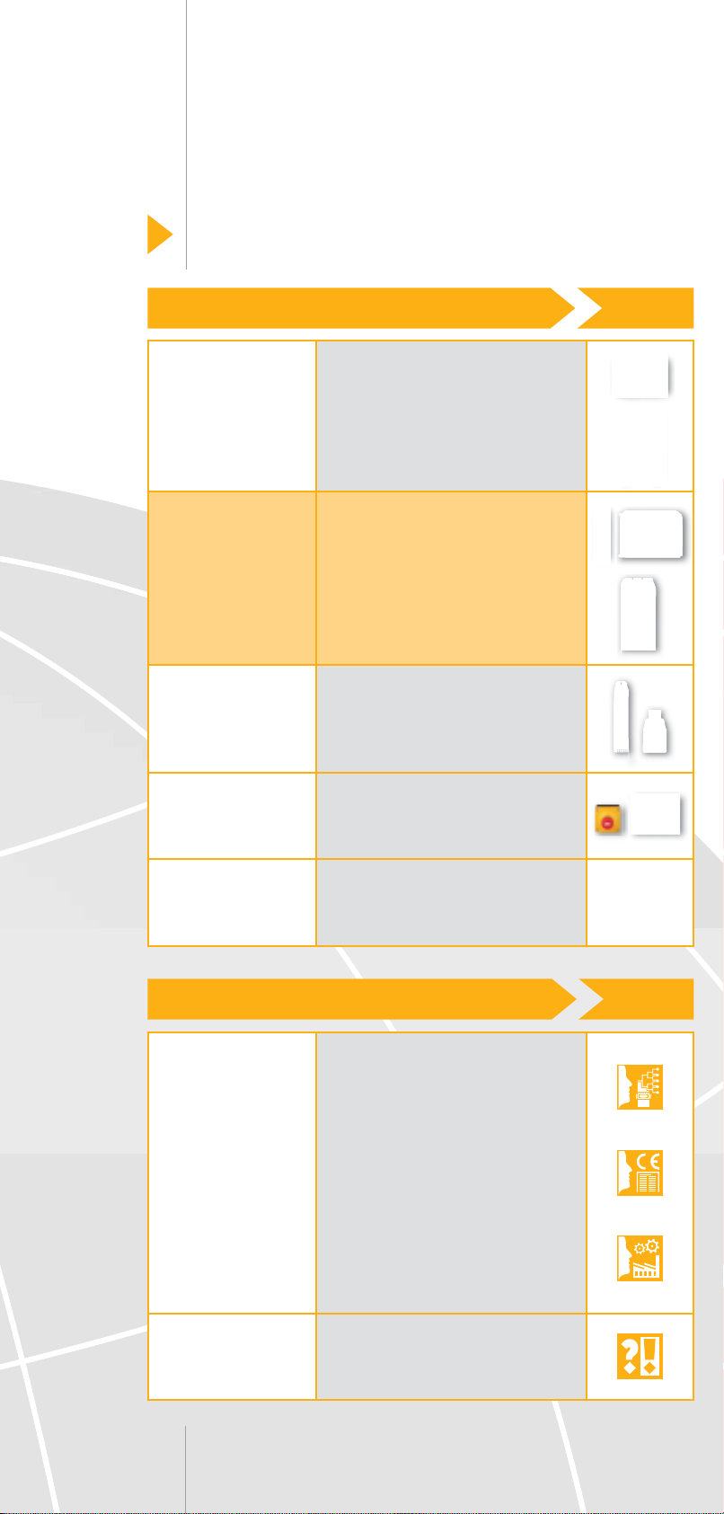
Business activities
Excellent Components
Sensor
technology
Control and
communication
Motion Control
Operating and
monitoring
Software
• Safety switches
• Secure safety gate systems
• Optoelectronic
protective devices
• Safe camera systems
• Electronic monitoring relays
• Safety relays
• Programmable
safety and control systems
• Industrial communication
• Control systems
• Servo amplifi ers
• Motors
• Control and signal devices
• Operator terminals
• System software
• User software
• Software tools
Professional Services
Consulting and
engineering
Training
• Risk assessment
• Safety concept
• Safety design
• System implementation
• Safety validation
• CE services
• International compliance
services
• Plant assessment
• Inspection of ESPE
• Seminars
• Courses
Page 3

Support
Technical help round the clock!
Technical support is available
from Pilz round the clock. This
service is provided free of charge
beyond standard business hours.
Americas
• Brazil
+55 11 8245-8267
• Mexico
+52 55 5572 1300
• USA (toll-free)
+1 877-PILZUSA (745-9872)
Asia
• China
+86 21 62494658-216
• Japan
+81 45 471-2281
• Korea
+82 2 2263 9540
Australia
• Australia
+61 3 95446300
You can reach our
international hotline on:
Europe
• Austria
+43 1 7986263-0
• Belgium, Luxembourg
+32 9 3217575
• England
+44 1536 462203
• France
+33 3 88104000
• Germany
+49 711 3409-444
• Ireland
+353 21 4804983
• Italy
+39 031 789511
• Scandinavia
+45 74436332
• Spain
+34 938497433
• Switzerland
+41 62 88979-30
• The Netherlands
+31 347 320477
• Turkey
+90 216 5452912
+49 711 3409-444
Pilz GmbH & Co. KG
Felix-Wankel-Straße 2
73760 Ostfi ldern, Germany
Telephone: +49 711 3409-0
Telefax: +49 711 3409-133
E-Mail: pilz.gmbh@pilz.de
Internet: www.pilz.com
Page 4

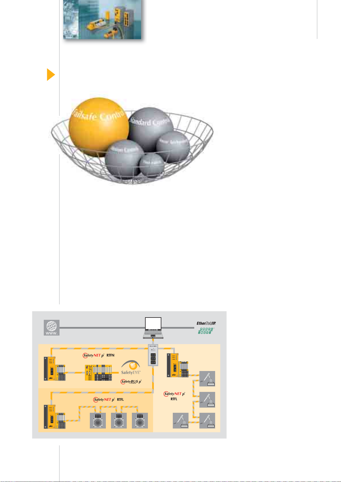
Why does Pilz offer more?
Because the integrality
of our business activities is
what sets us apart.
O
S
O
S
E
L
E
L
T
T
E
E
L
L
P
P
M
M
O
O
C
C
E
x
c
e
l
l
e
n
C
t
o
m
p
o
n
e
n
t
s
F
F
O
O
R
R
S
S
A
A
F
F
E
E
U
U
T
T
I
I
O
O
N
N
S
S
l
a
n
o
i
s
s
e
f
o
r
P
s
e
c
i
v
r
e
S
N
N
O
O
I
I
T
T
A
A
M
M
A
A
O
O
U
T
U
T
Pilz is a solution supplier for
all automation functions.
Including standard control functions. Developments from Pilz
protect man, machine and the
environment. That's why all our
experience and knowledge goes
into individual products as well
as consistently sophisticated
system solutions.
• Sensor technology
• Control and communication
• Motion Control
• Operating and monitoring
• Software
• Consulting and engineering
• Training
Appropriate services relating
to individual components and
independent generic services
guarantee that our customers
obtain customised automation
solutions, all from one source.
Pilz is a family business
that's closer to its customers.
Pilz has a tradition as a
family-run company stretching
back 60 years.
Real proximity to customers
is visible in all areas, instilling
confi dence through individual
consultation, fl exibility and
reliable service.
We are your contact, guide and
competency leader en route to an
optimum automation solution.
2
Page 5
E
C
x
o
c
e
m
F
F
O
O
C
C
l
p
O
O
l
e
o
R
R
M
M
n
n
S
S
P
P
t
A
e
A
L
L
n
F
F
E
E
Contents
O
S
O
S
E
E
T
T
t
s
E
E
A
A
U
U
T
T
L
L
O
O
U
U
M
M
P
S
T
T
I
r
e
A
A
I
o
O
O
r
T
T
v
f
N
e
I
I
N
c
i
O
O
S
s
S
N
N
s
e
• Pilz product areas ............................................. 4
• Product area
Control and communication ............................ 6
• Product group
Industrial communication ................................ 8
l
a
n
o
i
s
- SafetyNET p system features .......................... 10
- SafetyBUS p system features .......................... 14
- Safety Network International e. V. ................... 17
- InduraNET p system features .......................... 18
- General communication networks ................... 21
• Product group
PSS programmable safety
and control systems ......................................... 22
- PSSmodular systems ...................................... 24
- PSScompact systems ..................................... 32
- Decentralised periphery
and network components ................................ 40
- System software .............................................. 62
- Software function blocks ................................. 63
Safe automation from Pilz
As fl exible as your plant is
On complex machinery and distributed plants, PSS programmable safety and control systems
monitor safety-related functions
and/or undertake complete
control of the machine – whether
centralised or decentralised
via the safe, open bus system
SafetyBUS p.
Pilz PSS programmable safety
and control systems control
and monitor the widest range of
applications worldwide. The
comprehensive control system
portfolio provides fl exibility in
the way devices are combined,
so that numerous application
options are covered.
Innovation is our motto!
We work closely with customers
to continually develop the
PSS programmable safety and
control systems. New technologies – such as the real-time
Ethernet system SafetyNET p or
the wireless InduraNET p system
for industrial use – open up new
horizons in control technology.
• PVIS diagnostic concept .................................. 68
• Index ................................................................... 71
3
Page 6
O
C
Safety
Control
A
U
T
O
Pilz product areas
Solution suppliers for safety and standard
Pilz offers a universal concept
P
L
M
E
T
E
right across industry. Whether
you need safety or standard
control functions, machine or
for solutions that can be applied
N
O
I
T
M
A
plant, centralised or decentralised, a single product or a total
solution: With Pilz you will
defi nitely fi nd a solution for
your automation function.
Are you looking for a fl exible
solution for your automation
functions? Then you’ve come
to the right place!
Your requirements: Our solution:
PMDsrange
electronic monitoring relays
• PMDsrange: Electronic
monitoring relays for electrical
safety, such as voltage or true
power monitoring.
• PNOZ: Safety relays for
functional safety, for simple
plant and machinery with
up to 14 safety functions.
Safe monitoring of E-STOPs,
safety gates and light curtains/
light grids, in compliance with
the standards.
• PSS: Programmable safety
and control systems for use
on complex machinery or
distributed plants, to monitor
safety-related functions and/or
for complete machine control.
• Industrial communication:
Transfer input/output signals
and control data reliably
and safely.
PNOZ safety relays
PSS programmable
safety and control systems
Industrial
communication networks
4
Page 7
Supplementary
product areas:
Sensor technology
Products for safety
and standard
Besides “Control and
communication”, other product
areas also contain fi rst-class
components, which you can
use individually or combine to
form a system.
Sensor technology, used in
conjunction with Pilz safe control
technology, offers a co-ordinated,
complete solution that’s
economical, approved and safe.
The focus is always on the
protection of man and machine,
in compliance with the standards
and regulations.
Software includes system
software, user software and
software tools. Here you’ll fi nd
the right tool for every task.
From product-related software
to diagnostic software, through
to the PAScal Safety Calculator.
Services in the fi eld of machinery
safety are covered holistically
by Pilz. From risk assessment
through to ESPE inspection.
Pilz also offers a comprehensive
range of training courses and
seminars, covering generic issues
relating to machinery safety as
well as Pilz products.
Motion control
Operating and monitoring
Software
Services
Motion control offers complete,
safe, scalable drive technology
as part of the Pilz solution.
It provides overall solutions
for automating your machine,
from operation via the controller
through to the movement of
highly dynamic drives, including
all safety aspects.
Operating and monitoring
offers diagnostic and visualisation
devices, plus control and signal
devices as part of the Pilz
solution. The focus is always
on fast, simple confi guration.
Machine downtimes are clearly
reduced thanks to the overall
diagnostic concept PVIS.
The whole range
of business activities
at a glance:
Webcode 0326
Online information
at www.pilz.com
5
Page 8
O
C
Safety
Control
A
U
T
O
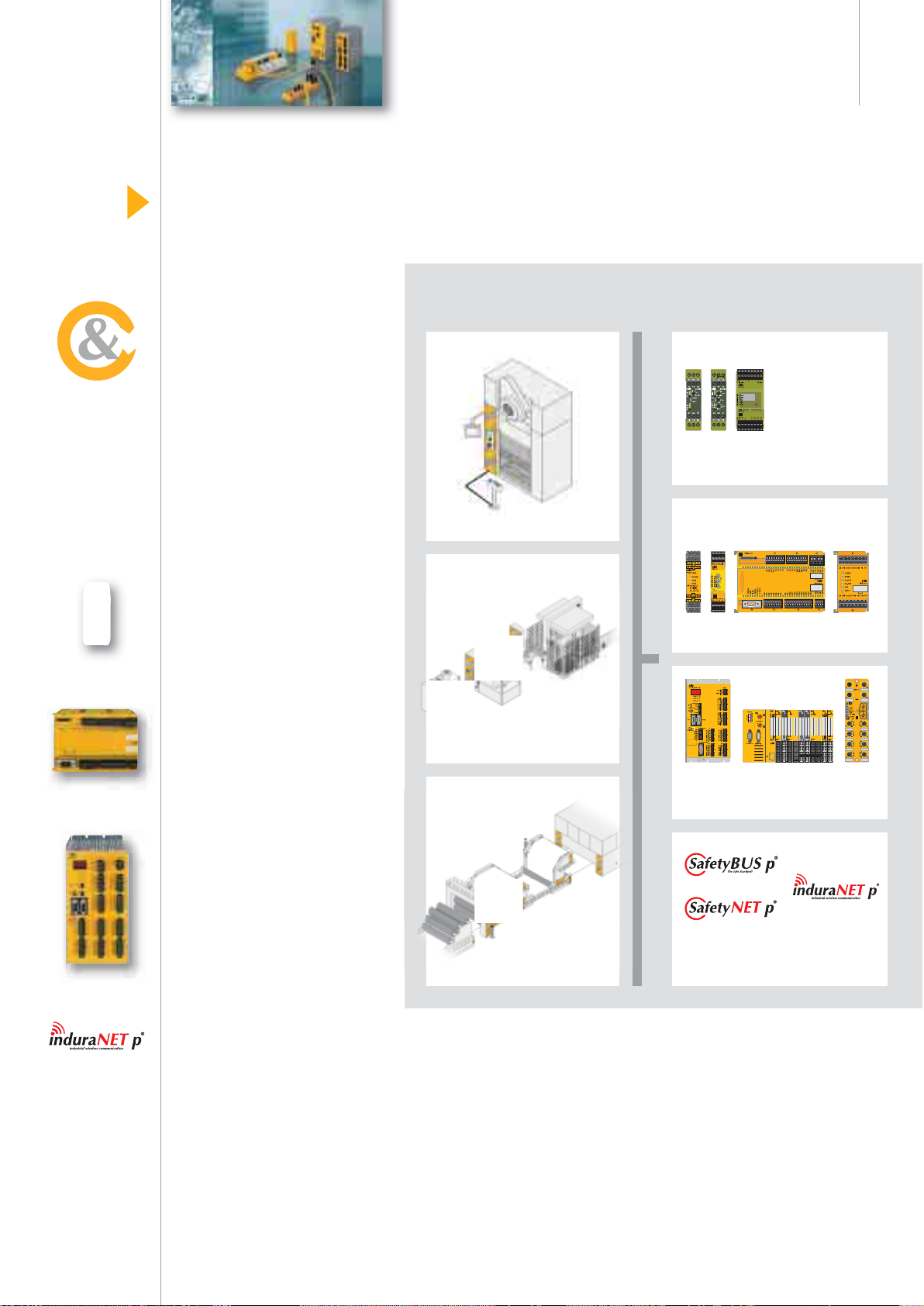
Product area
Control and communication
PSS® – The solution for standard and safety
Safe, economical, powerful
P
L
M
E
T
E
N
O
I
T
M
A
You can use Pilz PSS programmable safety and control systems
and the corresponding communication networks to implement
the widest range of automation
solutions – from the monitoring of
safety-related functions through
to the complete control of plant,
machinery and process cycles.
Your requirements
determine the system structure
• Stand-alone machine or plant
• Centralised or decentralised
architecture
• Safety-related or standard
control functions
Industrial communication
With Pilz industrial communication systems you can transfer
input/output signals safely
and reliably. Opt for the open,
real-time Ethernet SafetyNET p,
for example, which connects
the drive, safety and control
functions. Or you can network
your plant and machinery using
the safe, open bus system
SafetyBUS p. As a further
innovation, with the wireless
system InduraNET p Pilz has
developed a wireless solution
for an industrial environment.
6
Page 9
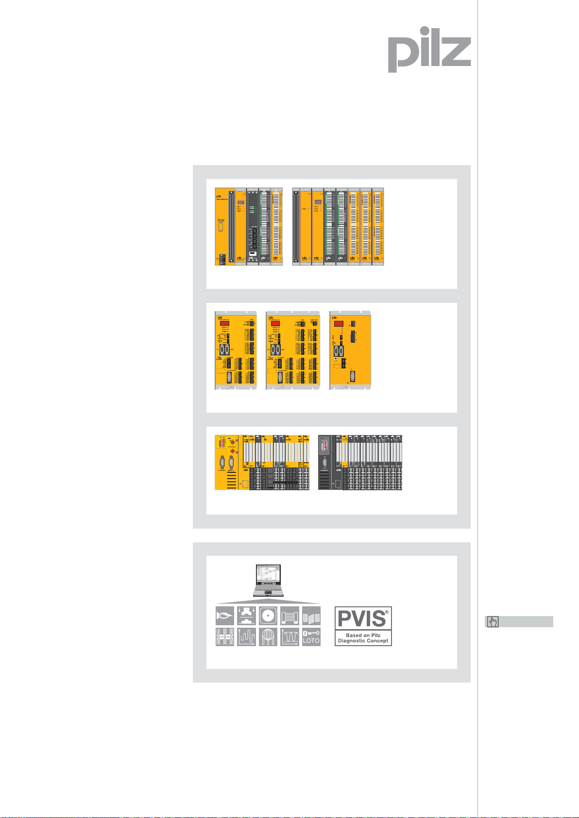
PSS programmable
safety and control systems
PSS programmable safety and
control systems are available in
a compact or modular design,
central and decentralised, for
direct fi eld application.
PSSmodular
For safety and control:
Assemble your individual solution
for centralised and decentralised
tasks – in accordance with your
requirements.
PSScompact
Six series covering safety
and control: Benefi t from an
extensive selection of versatile,
space-saving control solutions.
PSSuniversal
The decentralised I/O system
for safety and control: Cover the
complete input/output level with
just one system.
System software for
PSS programmable safety
and control systems
Practical software tools and
an extensive selection of
approved software function
blocks provide support as you
design and program your PSS
safety and control systems – from
planning through to diagnostics.
PSSmodular
PSScompact
PSSuniversal
System software
PSS SB 3006-3 ETH-2
RUN ST
RUN FS
POWER
AUTO PG
SPS
ST
PG
F-STACK
RUN
FS
STOP
PG USER
ON OFF
R (USER)
T
PSS PWR
1
24 V
X0
0 V
3
0 V
1
T 0
T 1
I0.0
X1
I0.1
I0.2
I0.3
I0.4
9
I0.5
ETHERNET
LINK
10/100 BASE T
TRAFFIC
LINK
10/100 BASE T
TRAFFIC
STATUS SB
SafetyBUS p
Keep up-to-date on
PSS programmable
safety and control
systems:
Webcode 0527
Online information
at www.pilz.com
7
Page 10
O
C
Safety
Control
A
U
T
O
Product group
Industrial communication
Backbone of safe automation
Data transfer –
P
L
M
E
T
E
N
O
I
T
M
A
Safe and reliable
Automation solutions are based
on reliable communication
networks. With its different
networks, Pilz offers the solution
for a range of requirements.
Whether you want wireless data
transfer or real-time – you’re
well advised to go for Pilz
communication networks.
Thanks to interfaces to all
other common fi eldbus systems
and Ethernet, you remain
independent in your choice
of control concept.
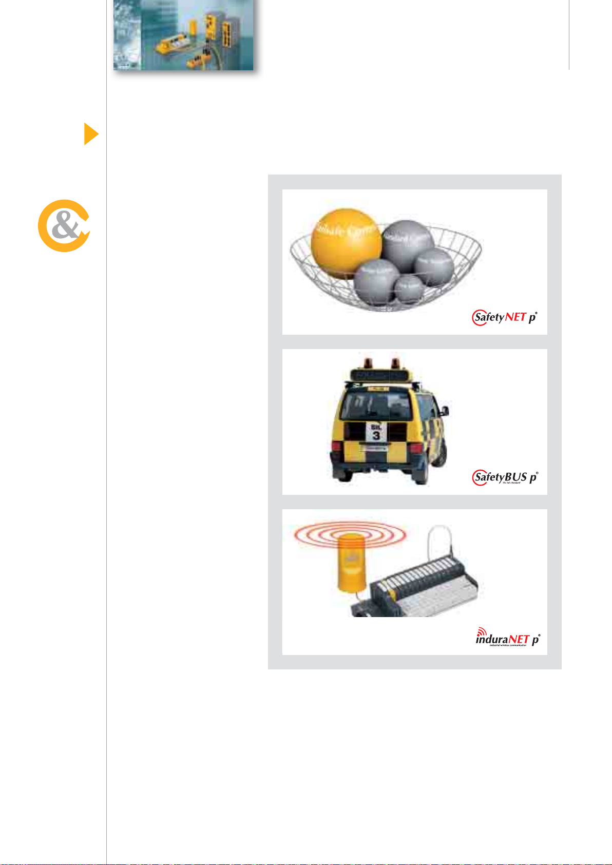
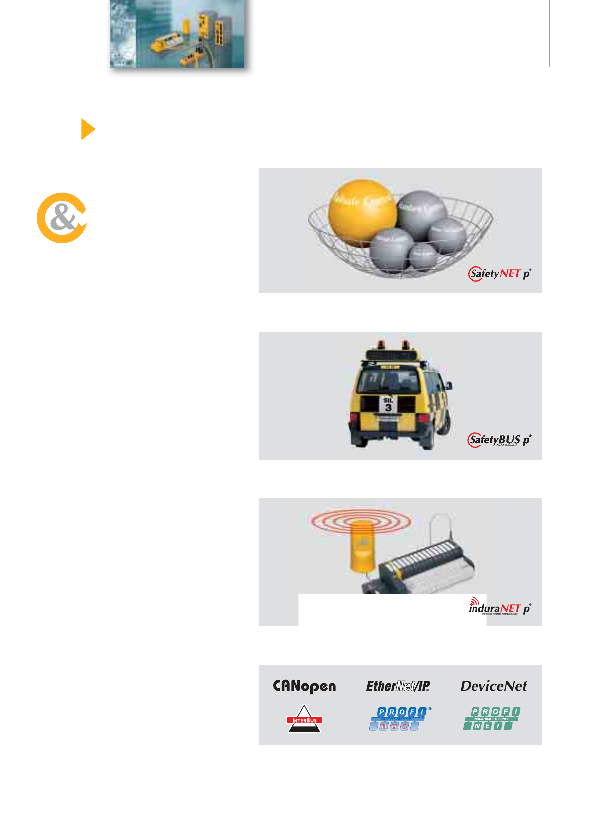
SafetyNET p – Real-time Ethernet for complete automation.
SafetyBUS p – The safe, open bus system.
InduraNET p – Reliable wireless technology
for the rugged everyday industrial environment.
Optimum integration – Thanks to an open system connection.
8
Page 11
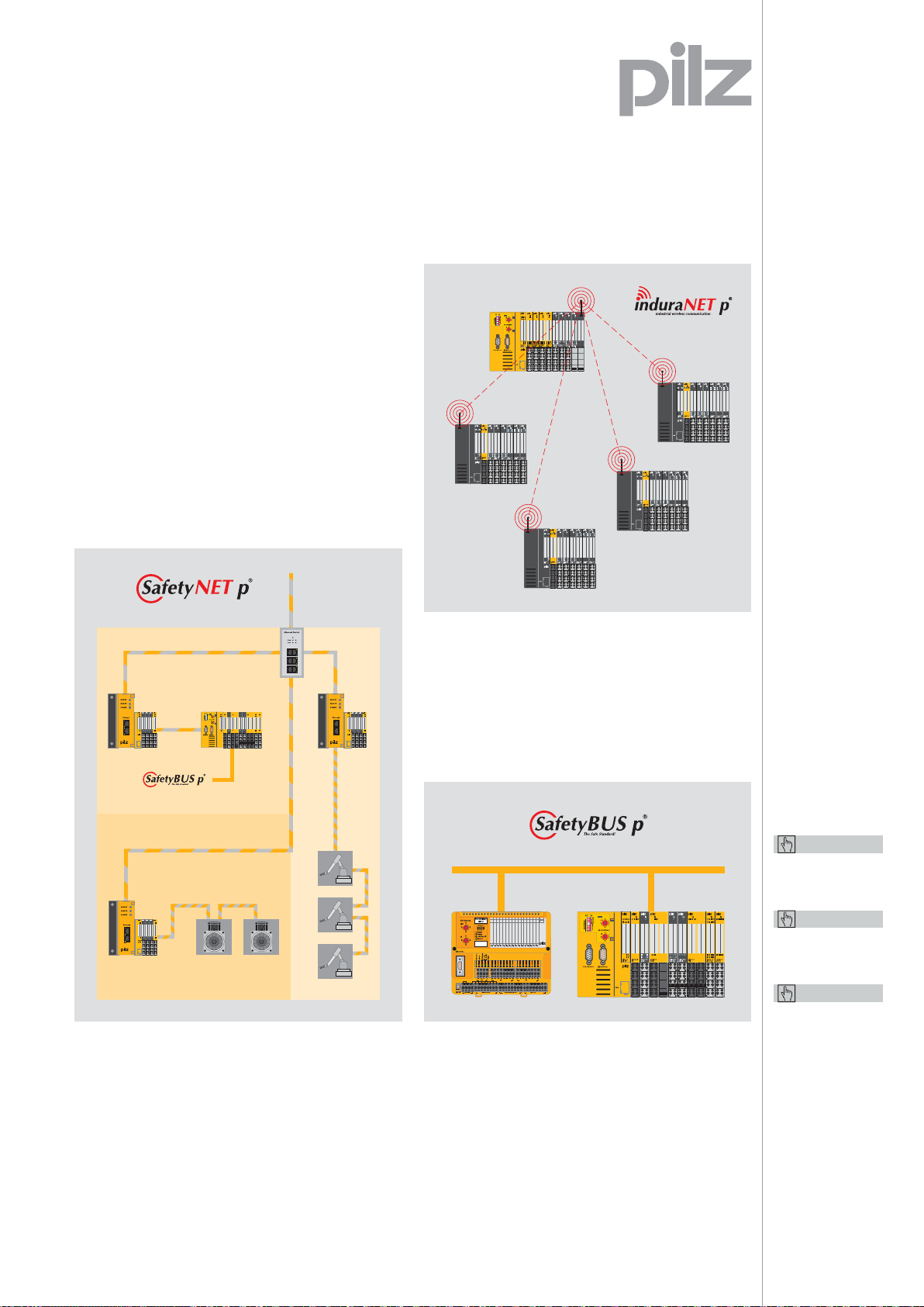
Pilz network systems
On large, complex and
distributed plants, control signals
are input/output directly in the
fi eld. This requires powerful,
available automation networks.
• With the wireless InduraNET p system, which
has been specially developed for industrial use,
signals can be exchanged with mobile devices,
for example.
• The open Ethernet system SafetyNET p can
be used for the safe transfer of time-critical data
as well as for standard communication of the
complete plant control system. With dynamic
applications, data is transmitted in real-time.
Keep up-to-date on:
• SafetyBUS p
Webcode 2469
• SafetyNET p
Webcode 2541
• InduraNET p
Webcode 2605
Online information
at www.pilz.com
• With the safe, open bus system SafetyBUS p,
time-critical information can safely be transmitted
decentrally at fi eld level.
9
Page 12
System features
SafetyNET p
SafetyNET p® – Networking of plant and ma
Investment protection
and independence with
an open system
• Existing SafetyBUS p and
fi eldbus installations can be
connected to SafetyNET p
and operate in co-existence
• Existing installations with other
industrial Ethernet systems
such as PROFINET and
Ethernet/IP can be connected
to SafetyNET p
• Any Ethernet device, e.g. PC,
camera, printer, etc. can be
Real-time Ethernet for
complete automation
SafetyNET p is based on
standard Ethernet and can be
used simultaneously for real-time,
standard and safety-related
communication functions in
industrial automation:
• For the safe transfer of
time-critical, safety-related data
• For transferring information
from the standard control
process
• For real-time communication
of all signals in highly dynamic,
synchronised applications
All of a plant and machine’s
control functions are networked
using a single system.
connected to SafetyNET p;
IP-based Ethernet utilities
such as E-Mail, Internet or
streaming can also be used
across the network
New horizons in
control technology
SafetyNET p enables new
fl exibility at optimum cost for
complete networking of plant
and machinery. So the system
based on the Ethernet standard
opens up new horizons in
control technology:
10
• Decentralisation of the control
intelligence directly to fi eld level
• Ability to maintain a
centralised view
• Long-term, implementation of
functional machine modules
Page 13
chinery
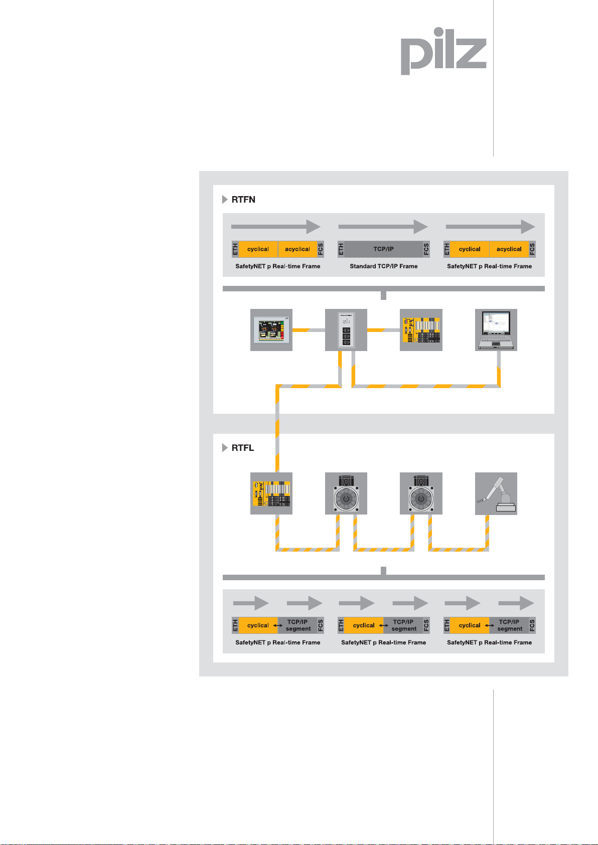
Individually adaptable
system standard with
two speed classes:
RTFN and RTFL
You can adapt SafetyNET p to
the widest range of automation
technology requirements and so
achieve the optimum cost-benefi t
ratio for your network design,
using just one system:
• For real-time communication
in highly dynamic applications,
e.g. on fi lling and packaging
machinery, use the RTFL speed
class (Real Time Frame Line)
with deterministically guaranteed scan times of 62.5 μs
and below
• For fi eldbus class
communication and for
networking individual production cells, use the RTFN speed
class with processing cycles of
approx. 1 ms – this is designed
for connecting a large number
of subscribers and for large
network extensions
11
Page 14
System features
SafetyNET p
SafetyNET p® – As fl exible as your plant is
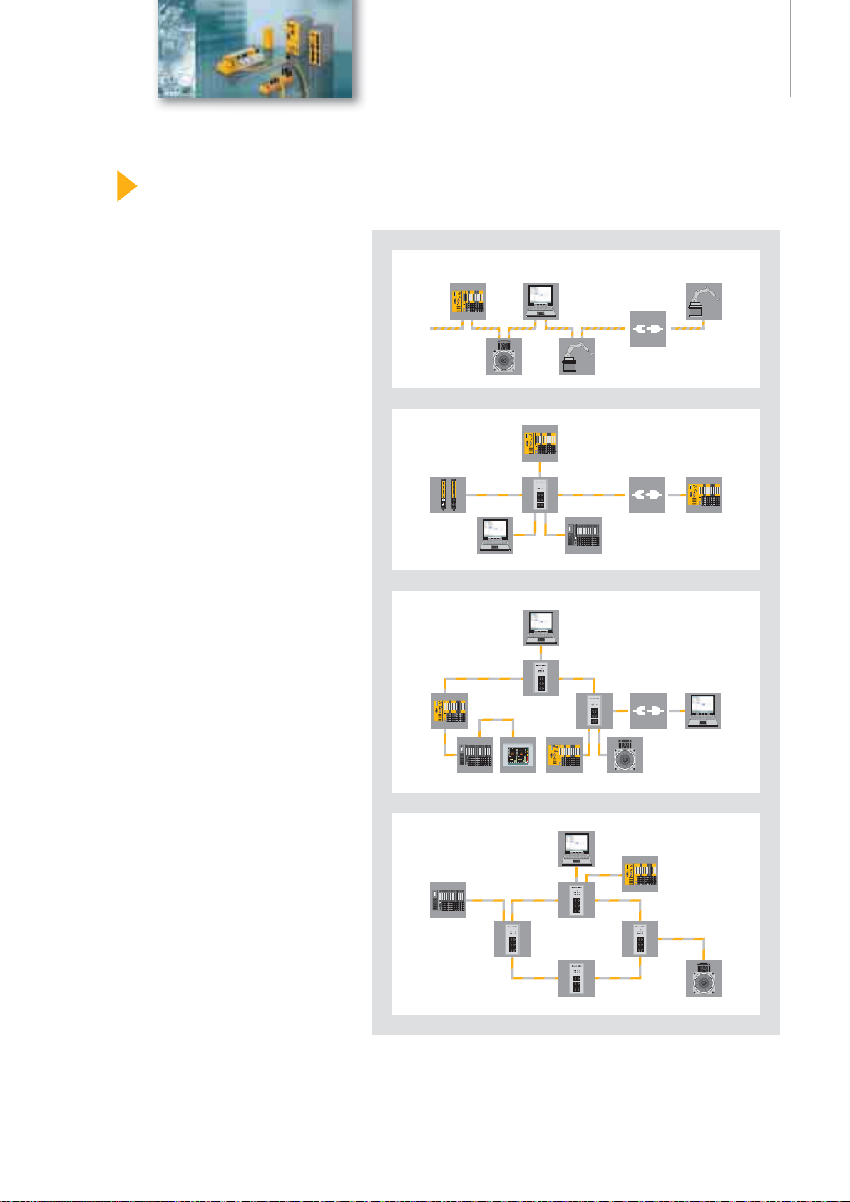
Flexible topologies
and dynamic structures
SafetyNET p supports the
widest range of topologies.
The application options are
many and varied:
• Linear structure – optimised
for rapid scan times and the
integration of existing bus
structures
• Star structure – data exchange
via a central node (e.g. CPU),
fl exibility in the way devices
can be connected and
disconnected from the network
• Tree structure – combination of
network segments with equal
or varied performance, ideal for
large, complex networks
• Ring structure – Redundancy
is guaranteed; if a component
should fail, a second route
can be used
Linear
Star
Tre e
OFF ON
-0
64
x10
32
16
369
8
4
2
ADDRESS
1
SB ADDRESS
0
x1
369
SafetyBUS p
PROFIBUS DP
11
21
11
21
11
21
11
21
11
21
11
21
11
21
12
22
12
22
12
22
12
22
12
22
12
22
12
22
13
23
13
23
13
23
13
23
13
23
13
23
13
23
USB
14
24
14
24
14
24
14
24
14
24
14
24
14
24
OFF ON
-0
64
x10
32
16
369
8
4
2
ADDRESS
1
SB ADDRESS
0
x1
369
SafetyBUS p
PROFIBUS DP
11
11
11
11
11
11
11
21
21
21
21
21
21
21
12
12
12
12
12
12
12
22
22
22
22
22
22
22
13
13
13
13
13
13
13
23
23
23
23
23
23
23
USB
14
14
14
14
14
14
14
24
24
24
24
24
24
24
OFF ON
-0
64
x10
32
16
369
8
4
2
ADDRESS
1
SB ADDRESS
0
x1
369
SafetyBUS p
PROFIBUS DP
11
21
11
21
11
21
11
21
11
21
11
21
11
21
12
22
12
22
12
22
12
22
12
22
12
22
12
22
13
23
13
23
13
23
13
23
13
23
13
23
13
23
USB
14
24
14
24
14
24
14
24
14
24
14
24
14
24
OFF ON
-64
32
16
8
4
2
ADDRESS
1
PROFIBUS DP
11
21
11
21
11
21
11
21
11
21
11
21
11
21
11
21
11
21
11
21
12
22
12
22
12
22
12
22
12
22
12
22
12
22
12
22
12
22
12
22
13
23
13
23
13
23
13
23
13
23
13
23
13
23
13
23
13
23
13
23
USB
14
24
14
24
14
24
14
24
14
24
14
24
14
24
14
24
14
24
14
24
All of the structures are dynamic.
Network subscribers can be
deactivated and replaced without
the need to reconfi gure the network. So you can connect mobile
devices if necessary, during
maintenance and diagnostics for
example, and implement variable
confi gurations within the production process, e.g. tool change.
Ring
OFF ON
-0
64
x10
32
16
369
8
4
2
ADDRESS
1
SB ADDRESS
0
x1
369
SafetyBUS p
PROFIBUS DP
11
21
11
21
11
21
11
21
11
21
11
21
11
21
12
22
12
22
12
22
12
22
12
22
12
22
12
22
13
23
13
23
13
23
13
23
13
23
13
23
13
23
USB
14
24
14
24
14
24
14
24
14
24
14
24
14
24
OFF ON
-0
64
OFF ON
-64
32
16
8
4
2
ADDRESS
1
PROFIBUS DP
11
21
11
21
11
21
11
21
11
21
11
21
11
21
11
21
11
21
11
21
12
22
12
22
12
22
12
22
12
22
12
22
12
22
12
22
12
22
12
22
13
23
13
23
13
23
13
23
13
23
13
23
13
23
13
23
13
23
13
23
USB
14
24
14
24
14
24
14
24
14
24
14
24
14
24
14
24
14
24
14
24
OFF ON
-64
32
16
8
4
2
ADDRESS
1
PROFIBUS DP
11
21
11
21
11
21
11
21
11
21
11
21
11
21
11
21
11
21
11
21
12
22
12
22
12
22
12
22
12
22
12
22
12
22
12
22
12
22
12
22
13
23
13
23
13
23
13
23
13
23
13
23
13
23
13
23
13
23
13
23
USB
14
24
14
24
14
24
14
24
14
24
14
24
14
24
14
24
14
24
14
24
x10
32
16
369
8
4
2
ADDRESS
1
SB ADDRESS
0
x1
369
SafetyBUS p
PROFIBUS DP
11
21
11
21
11
21
11
21
11
21
11
21
11
21
12
22
12
22
12
22
12
22
12
22
12
22
12
22
13
23
13
23
13
23
13
23
13
23
13
23
13
23
USB
14
24
14
24
14
24
14
24
14
24
14
24
14
24
OFF ON
-0
64
x10
32
16
369
8
4
2
ADDRESS
1
SB ADDRESS
0
x1
369
SafetyBUS p
PROFIBUS DP
11
11
11
11
11
11
11
21
21
21
21
21
21
21
12
12
12
12
12
12
12
22
22
22
22
22
22
22
13
13
13
13
13
13
13
23
23
23
23
23
23
23
USB
14
14
14
14
14
14
14
24
24
24
24
24
24
24
12
Page 15
Benefi ts at a glance
SafetyNET p
Safety right from the start
With SafetyNET p, the transfer of
safety-related data and standard
control information across a
system is physically mixed but
logically separate, and therefore
free from feedback. The safety
protocol is considered within
the system right from the start
and not just added later: The
protocol structure guarantees
stable network communication;
telegrams containing safetyrelated information, such as
a person entering a plant’s
danger zone, arrive safely at
the intended recipient.
Your benefi ts at a glance
• Open, individually adapt-
able network solution for all
automation functions
• Safety right from the start
• Based on the
Ethernet standard
• Real-time communication
for highly dynamic applications
• Flexible topology design
• Dynamic structures when
swapping subscribers
• Short scan times of
up to 62.5 μs
• High performance through
cross-communication
• Open connection to existing
system architectures
High performance through
cross-communication
All network components
have equal rights and can
both use and provide utilities.
Cross-communication enables
the decentralised processing of
data between two subscribers,
without calling on a central
instance (producer/consumer
model). This saves time and
increases the network performance.
Keep up-to-date
on SafetyNET p:
Webcode 2541
Online information
at www.pilz.com
Rapid reaction to
time-critical events
When used with distributed
real-time applications, information processing is synchronous
in accordance with IEE 1588.
A guaranteed system reaction
occurs at a precisely defi nable
time. With SafetyNET p networking, each device has a real-time
clock with interrupt function
to enable a rapid reaction to
time-critical events.
13
Page 16
System features
SafetyBUS p
SafetyBUS p® – Safe communication
In the fast lane
with SafetyBUS p
SafetyBUS p is used for the
safe, fast transfer of time-critical
information on decentralised
control structures. In a range
of industries, such as the automotive or packaging industry,
for example.
The bus system is based on the
CAN fi eldbus that is widely used
worldwide and has an additional
safety protocol that has been
approved by TÜV and BG. So
SafetyBUS p meets the increased
requirements of a safety bus in
terms of reaction times, safety
and absence of feedback during
signal transfer.
Parallel structure of
safety bus and fi eldbus
A plant’s standard automation
process must not be able to
infl uence the safety functions
in the case of an emergency.
This guarantees safe communication with SafetyBUS p, without
feedback.
Design guidelines issued by manufacturers and users often call for
a strict separation of safety and
standard control technology –
particularly on hazardous process
and manufacturing cycles.
Separation guarantees transparency and the allocation of
responsibility is clearly defi ned.
14
OFF ON
-64
32
16
8
4
2
ADDRESS
1
PROFIBUS DP
0
Usb 5V5VFS0 FS0
x10
369
SB ADDRESS
0
x1
369
PSSu H
SB DP
SafetyBUS p
USB
Err
Err Err Err
Err Err
Dev 24V 24V
I/O FS3SB
Run 21 SW 21 21 21
11
11142111
BF 24 24 24
14
PSSu E FPSPSSu E S
PSSu E F
PSSu E S
PSSu E S
4DI
BSW
4DO 0.5
2DO 2
11
11
11
11
11
21
21
21
21
12
12
12
12
12
22
22
22
22
13
13
13
13
13
23
23
23
23
14
14
14
14
14
24
24
24
24
OFF ON
Err
Err Err Err
Err11Err
Err Err
-0
Dev 24V 24V
24V
FS1 FS1
Usb 5V5VFS0 FS0
64
x10
32
I/O FS3SB
FS2
16
369
8
4
2
ADDRESS
1
SB ADDRESS
0
x1
369
Run 21 SW 21 21 21
11
11
11142111
BF 24 24 24
14
14
PSSu H
PSSu E FPSPSSu E S
PSSu E F
PSSu E S
PSSu E S
PSSu E F
PSSu E F
PSSu E F
SB DP
4DI
BSW
4DO 0.5
2DO 2
PS1
4DO 0.5
2DO 2
SafetyBUS p
PROFIBUS DP
11
11
11
11
11
11
11
11
11
21
21
21
21
21
21
21
21
21
12
12
12
12
12
12
12
12
12
22
22
22
22
22
22
22
22
22
13
13
13
13
13
13
13
13
13
23
23
23
23
23
23
23
23
23
USB
14
14
14
14
14
14
14
14
14
24
24
24
24
24
24
24
24
OFF ON
-64
32
16
8
4
2
ADDRESS
1
PROFIBUS DP
OFF ON
-64
32
16
8
4
2
ADDRESS
1
PROFIBUS DP
0
x10
369
SB ADDRESS
0
x1
369
SafetyBUS p
USB
0
x10
369
SB ADDRESS
0
x1
369
SafetyBUS p
USB
Err
Err Err Err
Dev 24V 24V
Usb 5V5VFS0 FS0
I/O FS3SB
Run 21 SW 21 21 21
11
11142111
BF 24 24 24
14
PSSu H
PSSu E FPSPSSu E S
PSSu E F
PSSu E S
SB DP
4DI
BSW
4DO 0.5
11
11
11
11
21
21
21
12
12
12
12
22
22
22
13
13
13
13
23
23
23
14
14
14
14
24
24
24
Err
Err Err Err
Dev 24V 24V
Usb 5V5VFS0 FS0
I/O FS3SB
Run 21 SW 21 21 21
11
11142111
BF 24 24 24
14
PSSu H
PSSu E FPSPSSu E S
PSSu E F
PSSu E S
SB DP
4DI
BSW
4DO 0.5
11
11
11
11
21
21
21
12
12
12
12
22
22
22
13
13
13
13
23
23
23
14
14
14
14
24
24
24
24
OFF ON
Err
Err Err Err
Err11Err
Err Err
-0
Dev 24V 24V
24V
FS1 FS1
Usb 5V5VFS0 FS0
64
x10
32
I/O FS3SB
FS2
16
Err11Err
Err Err
24V
FS1 FS1
FS2
11
14
PSSu E S
PSSu E F
PSSu E F
PSSu E F
2DO 2
PS1
4DO 0.5
2DO 2
11
11
11
11
11
21
21
21
21
21
21
12
12
12
12
12
22
22
22
22
22
22
13
13
13
13
13
23
23
23
23
23
23
14
14
14
14
14
24
24
24
24
24
24
Err11Err
Err Err
24V
FS1 FS1
FS2
11
14
PSSu E S
PSSu E F
PSSu E F
PSSu E F
2DO 2
PS1
4DO 0.5
2DO 2
11
11
11
11
11
21
21
21
21
21
21
12
12
12
12
12
22
22
22
22
22
22
13
13
13
13
13
23
23
23
23
23
23
14
14
14
14
14
24
24
24
24
24
24
8
4
2
ADDRESS
1
PROFIBUS DP
OFF ON
--
64
32
16
8
4
2
ADDRESS
1
PROFIBUS DP
369
SB ADDRESS
0
x1
369
Run 21 SW 21 21 21
BF 24 24 24
PSSu H
SB DP
SafetyBUS p
USB
0
Dev 24V 24V
Usb 5V5VFS0 FS0
x10
I/O FS3SB
369
SB ADDRESS
0
x1
369
Run 21 SW 21 21 21
BF 24 24 24
PSSu H
SB DP
SafetyBUS p
USB
11
11
11142111
14
14
PSSu E FPSPSSu E S
PSSu E F
PSSu E S
PSSu E S
PSSu E F
PSSu E F
PSSu E F
4DI
BSW
4DO 0.5
2DO 2
PS1
4DO 0.5
2DO 2
11
11
11
11
11
11
11
11
11
21
21
21
21
21
21
21
21
21
12
12
12
12
12
12
12
12
12
22
22
22
22
22
22
22
22
22
13
13
13
13
13
13
13
13
13
23
23
23
23
23
23
23
23
23
14
14
14
14
14
14
14
14
14
24
24
24
24
24
24
24
24
24
Err
Err Err Err
Err11Err
Err Err
24V
FS1 FS1
FS2
11
11
11142111
14
14
PSSu E FPSPSSu E S
PSSu E F
PSSu E S
PSSu E S
PSSu E F
PSSu E F
PSSu E F
4DI
BSW
4DO 0.5
2DO 2
PS1
4DO 0.5
2DO 2
11
11
11
11
11
11
11
11
11
21
21
21
21
21
21
21
21
21
12
12
12
12
12
12
12
12
12
22
22
22
22
22
22
22
22
22
13
13
13
13
13
13
13
13
13
23
23
23
23
23
23
23
23
23
14
14
14
14
14
14
14
14
14
24
24
24
24
24
24
24
24
24
OFF ON
Err
Err Err Err
Err11Err
Err Err
-0
Dev 24V 24V
24V
FS1 FS1
Usb 5V5VFS0 FS0
64
x10
32
I/O FS3SB
FS2
16
369
8
4
2
ADDRESS
1
SB ADDRESS
0
x1
369
Run 21 SW 21 21 21
11
11
11142111
BF 24 24 24
14
14
PSSu H
PSSu E FPSPSSu E S
PSSu E F
PSSu E S
PSSu E S
PSSu E F
PSSu E F
PSSu E F
SB DP
4DI
BSW
4DO 0.5
2DO 2
PS1
4DO 0.5
2DO 2
SafetyBUS p
PROFIBUS DP
11
11
11
11
11
11
11
11
11
21
21
21
21
21
21
21
21
21
12
12
12
12
12
12
12
12
12
22
22
22
22
22
22
22
22
22
13
13
13
13
13
13
13
13
13
23
23
23
23
23
23
23
23
23
USB
14
14
14
14
14
14
14
14
14
24
24
24
24
24
24
24
24
24
OFF ON
Err
Err Err Err
Err11Err
Err Err
-0
Dev 24V 24V
24V
FS1 FS1
Usb 5V5VFS0 FS0
64
x10
32
I/O FS3SB
FS2
16
369
8
4
2
ADDRESS
1
SB ADDRESS
0
x1
369
Run 21 SW 21 21 21
11
11
11142111
BF 24 24 24
14
14
PSSu H
PSSu E FPSPSSu E S
PSSu E F
PSSu E S
PSSu E S
PSSu E F
PSSu E F
PSSu E F
SB DP
4DI
BSW
4DO 0.5
2DO 2
PS1
4DO 0.5
Err11Err
24V
FS1 FS1
FS2
11
14
PSSu E F
PSSu E F
PSSu E F
PS1
4DO 0.5
2DO 2
11
11
11
11
21
21
21
21
21
12
12
12
12
22
22
22
22
22
13
13
13
13
23
23
23
23
23
14
14
14
14
24
24
24
24
24
OFF ON
Err
Err Err Err
Err11Err
Err Err
-0
Dev 24V 24V
24V
FS1 FS1
Usb 5V5VFS0 FS0
64
x10
32
I/O FS3SB
FS2
16
369
8
4
2
ADDRESS
1
SB ADDRESS
0
x1
369
Run 21 SW 21 21 21
11
11
11142111
BF 24 24 24
14
14
PSSu H
PSSu E FPSPSSu E S
PSSu E F
PSSu E S
PSSu E S
PSSu E F
PSSu E F
PSSu E F
SB DP
4DI
BSW
4DO 0.5
2DO 2
PS1
4DO 0.5
2DO 2
SafetyBUS p
PROFIBUS DP
11
11
11
11
11
11
11
11
11
21
21
21
21
21
21
21
21
21
12
12
12
12
12
12
12
12
12
22
22
22
22
22
22
22
22
22
13
13
13
13
13
13
13
13
13
23
23
23
23
23
23
23
23
23
USB
14
14
14
14
14
14
14
14
14
24
24
24
24
24
24
24
24
24
PROFIBUS DP
OFF ON
-64
32
16
8
4
2
ADDRESS
1
PROFIBUS DP
SafetyBUS p
USB
0
x10
369
SB ADDRESS
0
x1
369
SafetyBUS p
USB
11
11
11
21
21
21
12
12
12
22
22
22
13
13
13
23
23
23
14
14
14
24
24
24
Err
Err Err Err
Dev 24V 24V
Usb 5V5VFS0 FS0
I/O FS3SB
Run 21 SW 21 21 21
11
BF 24 24 24
14
PSSu H
PSSu E FPSPSSu E S
PSSu E F
SB DP
4DI
BSW
11
11
11
21
21
21
12
12
12
22
22
22
13
13
13
23
23
23
14
14
14
24
24
24
2DO 2
11
11
11
11
11
11
21
21
21
21
21
21
12
12
12
12
12
12
22
22
22
22
22
22
13
13
13
13
13
13
23
23
23
23
23
23
14
14
14
14
14
14
24
24
24
24
24
24
Err11Err
Err Err
24V
FS1 FS1
FS2
11
11142111
14
PSSu E S
PSSu E S
PSSu E F
PSSu E F
PSSu E F
4DO 0.5
2DO 2
PS1
4DO 0.5
2DO 2
11
11
11
11
11
11
21
21
21
21
21
21
12
12
12
12
12
12
22
22
22
22
22
22
13
13
13
13
13
13
23
23
23
23
23
23
14
14
14
14
14
14
24
24
24
24
24
24
Page 17
Benefi ts at a glance
SafetyBUS p
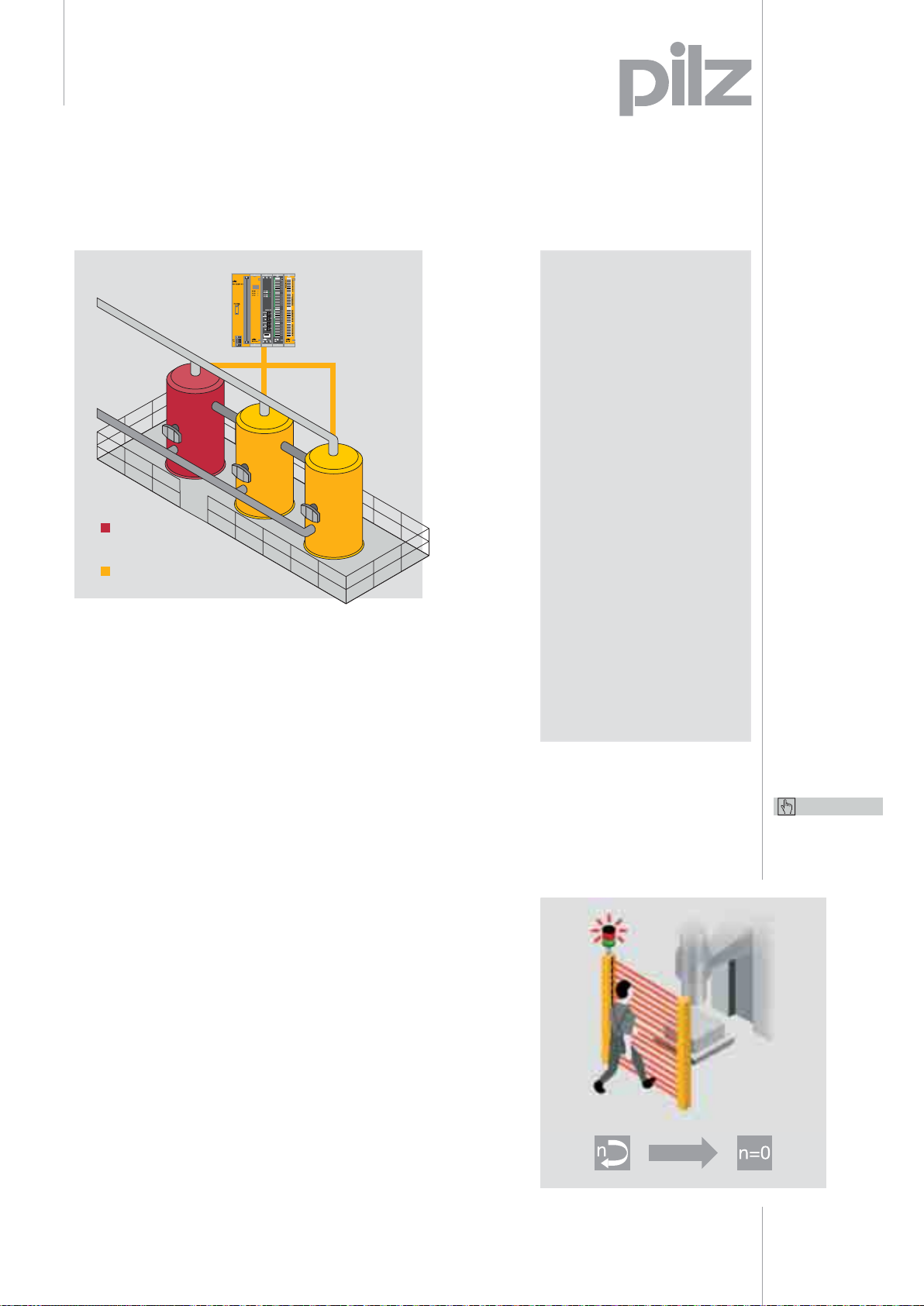
Burner
not in operation
Burner in operation
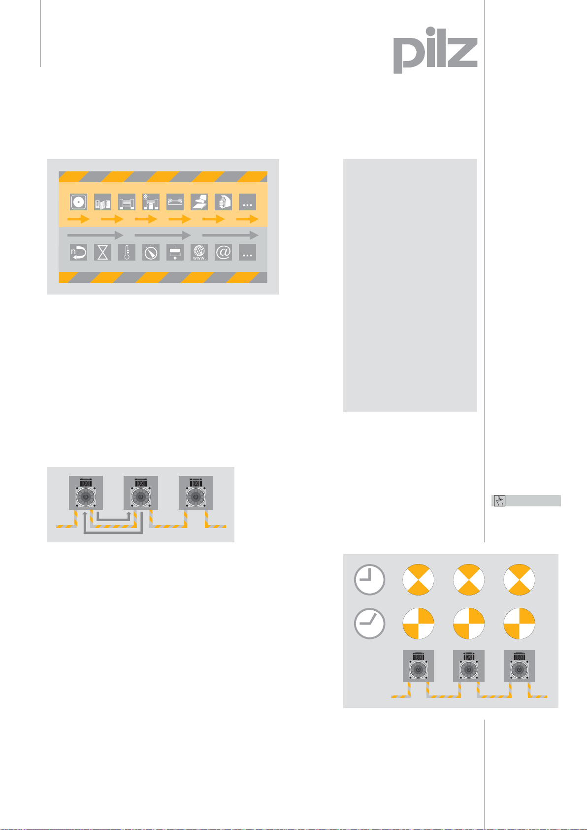
Few downtimes thanks
to safe selective shutdown
Each SafetyBUS p subscriber
can be assigned to a group.
Within an application, plant
sections that belong together
logically can be confi gured
as groups and switched off
separately in the case of an error.
Modular
safety and
control system
PSS 3100
The rest of the production cycle
continues unhindered – enabling
productive work practices.
Generic functions, such as an
E-STOP of the entire plant,
are assigned to all groups.
With up to 32 groups within a
SafetyBUS p network, it is
possible to build up complex
structures.
Your benefi ts at a glance
• Decentralised, safe
networking of sensors
and actuators
• The safety technology
does not have to be hardwired, as the signal is transferred via the bus cable
• Meets the highest
safety requirements
in accordance with
international standards
• Rapid reaction times
to hazardous events
thanks to event-driven
communication
• Extremely short error
reaction times of 25 ms
and shorter
• Few downtimes thanks to
integrated diagnostics
• Large network extension
up to 4,032 inputs and
outputs
Keep up-to-date
on SafetyBUS p:
Webcode 2469
Online information
at www.pilz.com
Fast reaction times thanks to
event-driven communication
SafetyBUS p operation is
event-driven. This means that
messages are only sent when the
status changes at the centralised/
decentralised inputs/outputs or
at the bus subscribers. For this
reason, SafetyBUS p is especially
suitable for networking plants
with different signalling rates and
high reaction time requirements.
Short reaction times have the
additional advantage that
protective measures (e.g. safety
gates or light grids) can be
positioned close to the danger
zone – saving space and costs.
If a hazardous event occurs, the
PSS programmable safety and control
systems will react particularly quickly.
t = min
15
Page 18
Applications and industries
SafetyBUS p
SafetyBUS p® – proven across industry
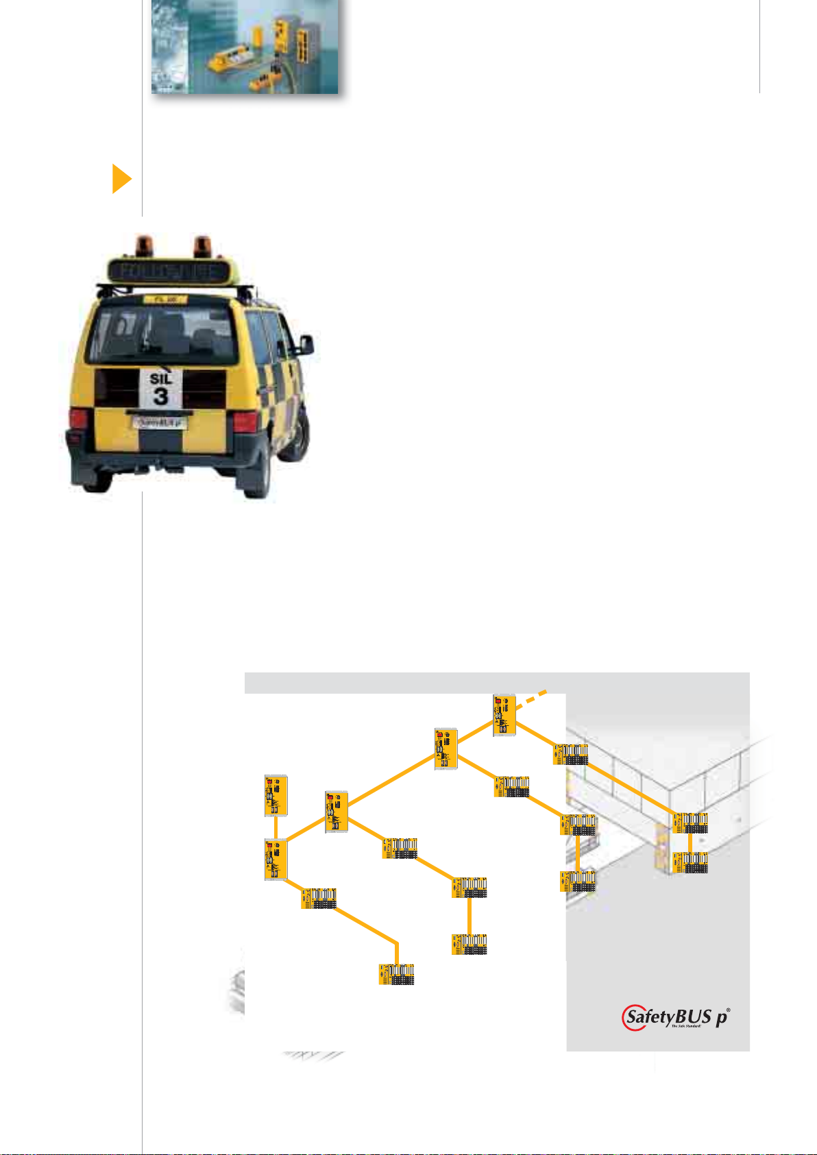
Visible success
The safe bus system
SafetyBUS p is used for the safe,
fast transfer of time-critical information on decentralised control
structures. It is used across a
range of industries in conjunction
with PSS programmable safety
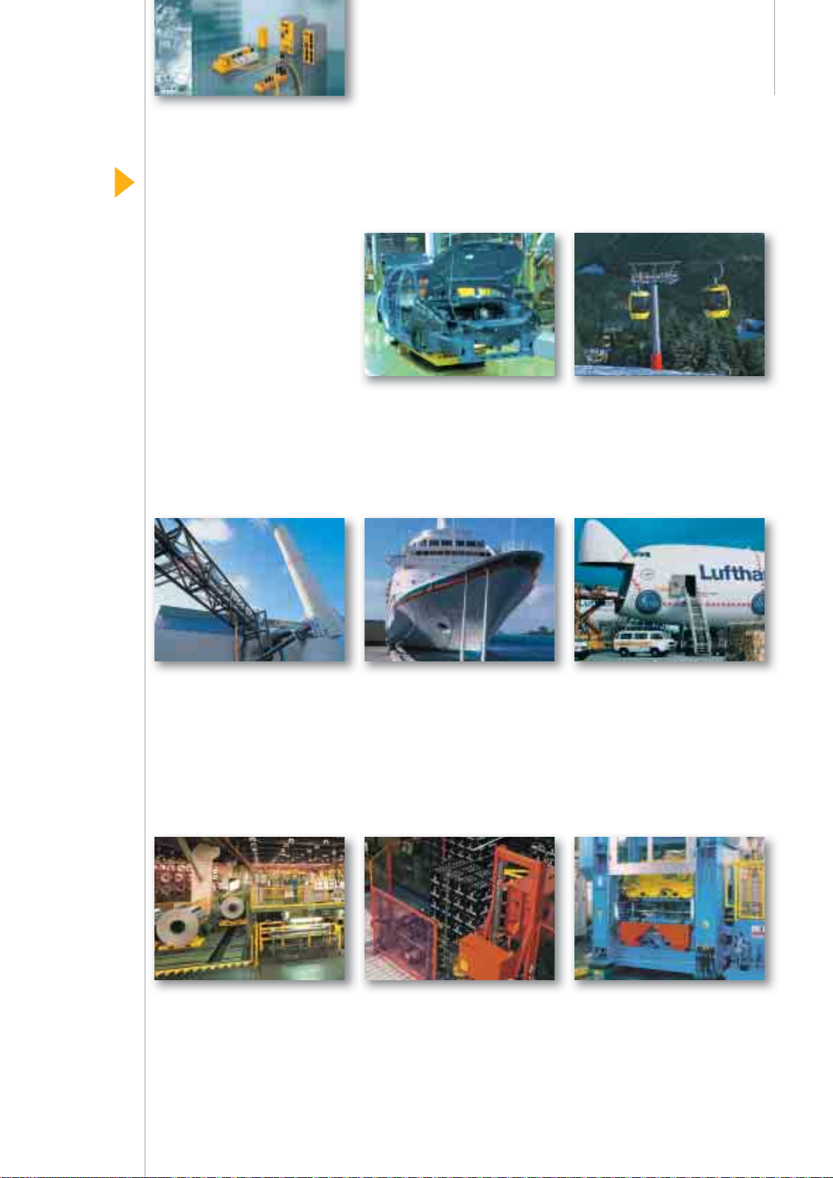
and control systems: Automotive industry –
Monitoring production processes
in the press shop, body plant,
transmission, fi nal assembly
and paint shop
Cablecar technology –
Moni toring the entire route,
from entry to exit, distance
between the cars and recognition
of rope layers
Process technology –
Safe monitoring and control
of furnaces, monitoring valves,
fi ll levels and fuel/air ratios
Steel and aluminium
processing – Safe monitoring
during maintenance and restart
Conveyor technology –
Safe track and load monitoring,
collision detection on crane and
harbour applications, container
loading and lifting platforms
Packaging industry – Safe
monitoring of fi lling, picking and
packaging processes
Airport automation – Flexible
control and safe monitoring of
fi lling stations, combined heat
and power stations, rolling
hangar doors, baggage handling
systems and transport systems
Presses – Economical application
on stand-alone presses or on
press lines
16
Page 19
Safety Network
International e. V.
Safety Network International e. V.
The open forum for
safety and automation
Safety Network International e. V.
is an independent organisation
which, as well as promoting the
proven SafetyBUS p system, also
supports the Ethernet-based
system SafetyNET p.
Members include users, integrators and manufacturers of both
systems. The organisation was
founded in 1999 and now has
75 member companies.
The work carried out by
Safety Network International
e. V. guarantees users and
participating manufacturers that
the SafetyNET p system will
remain open and future-proof.
Tasks and projects:
• Investment protection for users
and manufacturers through
continual development and
support of SafetyBUS p and
SafetyNET p technology
• Sales promotion through
active press relations and
exhibition attendance
• Development of profi les
and specifi cations to simplify
handling of SafetyBUS p
and SafetyNET p
• Quality assurance through
the establishment of test
laboratories, device certifi cation,
monitoring of interoperability
and conformity
• Lobbying within standards
committees and associations
on behalf of the member
companies of Safety Network
International e. V.
• Assure worldwide propagation
by infl uencing international
standardisation
Machinery safety forum
With the machine safety forum,
Safety Network International e. V.
has created an important medium
for providing quick, effective
communication regarding
changes within the standards
fi eld and new regulations.
Safety Network Academy
Safety Network International e. V.
promotes the Safety Network
Academy in conjunction with
its member organisations.
The network's aim is to encourage knowledge transfer among
the participating institutions
and organisations.
Safety Network integration
As the umbrella organisation for
SafetyBUS p and SafetyNET p,
Safety Network International e. V.
hosts events to present automation suppliers with options for
implementing these technologies
in their own devices and components.
Find out more about Safety
Network International e. V.:
www.safety-network.org
17
Page 20
System features
InduraNET p
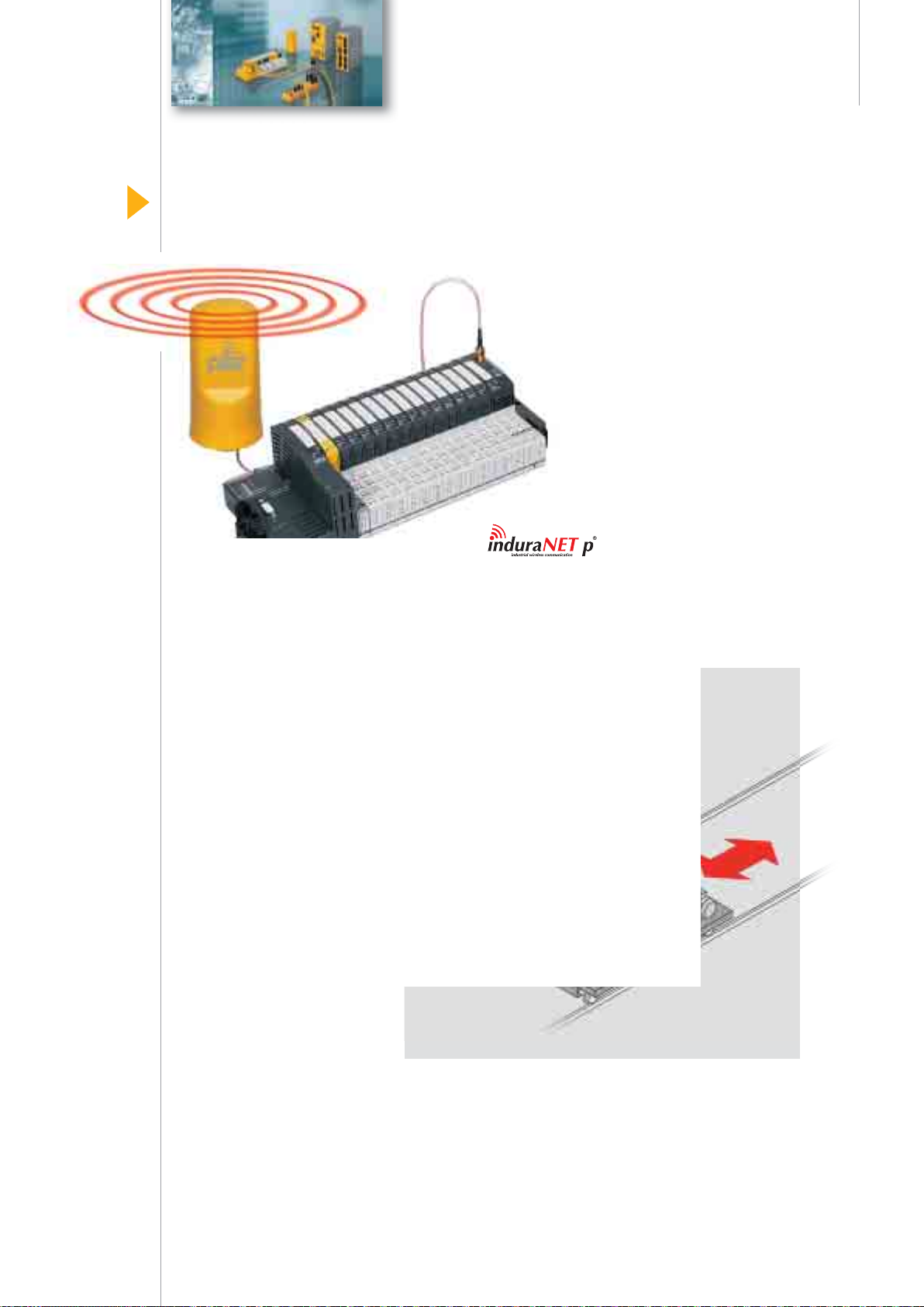
InduraNET p® – Reliable wireless technolo
A different way of broadcasting
The wireless system InduraNET p
(Industrial Radio Network) is
specifi cally designed for use in
an industrial environment.
Anywhere that a cable-based
solution is diffi cult if not impossible to install, InduraNET p
can help. Key features include a
particularly robust communication technology, high availability
due to a new type of antenna
system and a high coexistence
capability with other wireless
services.
Wireless compensates
for the disadvantages
of contact-based solutions
Mobile devices frequently use
trailing cable and drag chains,
rotary transformers and slip ring
transmitters, as well as data
light beam devices and cables.
These moving parts are subject
to wear, maintenance intensive
and complex to install. With its
special technology, the wireless
InduraNET p system compensates for the weaknesses of
contact-based solutions.
Wireless signal transfer via InduraNET p
in plants with moving parts.
18
Page 21
gy for industry
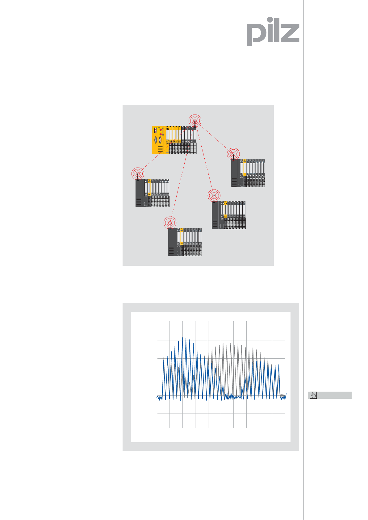
System solution
with PSSuniversal
InduraNET p is integrated within
the decentralised I/O system
PSSuniversal. A module is incorporated into the base station in
order to be able to use the wireless
technology. All remote stations
follow the slot addressing of the
base station, without occupying
a slot themselves. The head
module on the base station
“sees” all the remote components as a series of electrical
modules. Up to four remote
stations that are used in parallel
can be connected to each
base station.
The wireless
modules, antennas
etc. for the
decentralised
I/O system can
be found on
page 52/53.
High availability thanks
to a special antenna system
Antennas are required to enable
the PSSuniversal head modules
to process wireless information.
Both a single and a dual antenna
are available for InduraNET p.
The dual antenna contains
multiple subantennas, from which
the best receiver at any given
time can be used. This compensates for any interference in the
wireless zone. The dual antenna
is mainly used where communication conditions are poor.
Decentralised signal transfer via InduraNET p –
Centralised view of a decentralised structure.
-65 dBm
-70 dBm
-75 dBm
-80 dBm
-85 dBm
CF 2.439 GHz Span 70.0 MHz
Keep up-to-date
on InduraNET p:
Webcode 2605
Online information
at www.pilz.com
Consistently high reception quality: If one subantenna is barely able
to receive a usable signal, the other antenna will have a good signal.
19
Page 22
Benefi ts at a glance
InduraNET p
InduraNET p® – Innovative wireless system
Keep up-to-date
on InduraNET p:
Webcode 2605
Online information
at www.pilz.com
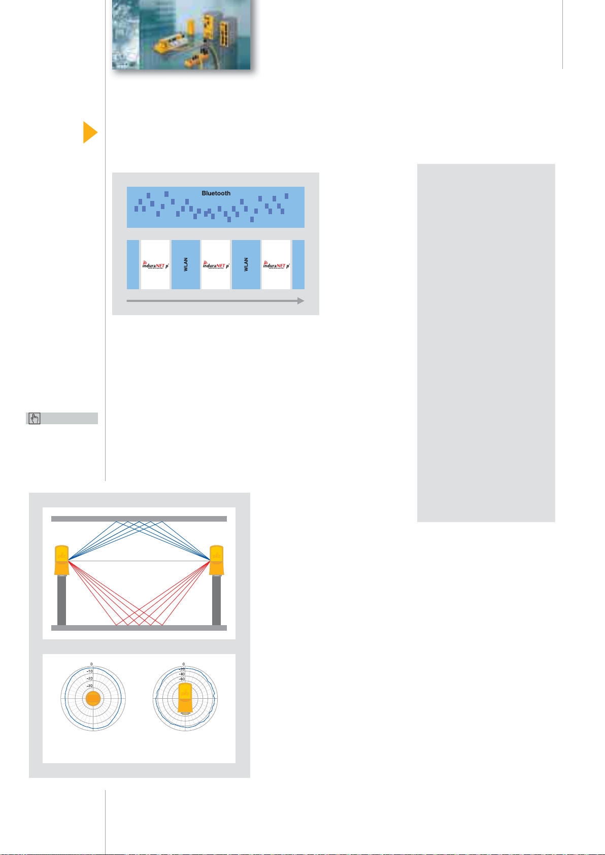
Coexistence with
other wireless services
Unlike Bluetooth wireless systems, for example, InduraNET p
does not infl uence any other
industrial wireless systems
thanks to its intelligent frequency
management (CFM). In addition
to the protocol mechanism, the
Coexistence
with other
wireless services.
access mechanism “Listen before
talk” guarantees that the radio
channel is available and is not
in use by any other wireless services. At the same time, the WLAN
channels that are identifi ed as
busy are permanently “marked”
and hidden. This means that
collisions or mutual interference
with WLAN are excluded.
Your benefi ts at a glance
• Easy accessibility within
the zone, which would not
be achievable with such
fl exibility using a cable
connection
• Particularly robust
communication technology
• Constant high quality
wireless connection
thanks to the innovative
antenna system
• Coexists with other
wireless services thanks
to intelligent frequency
management
• Easy to expand the
existing infrastructure,
so the work involved in
project confi guration and
installation is reduced
• Licence-free, uses
the free worldwide
ISM frequency bands
• Cost savings, as there is
less planning, installation
and maintenance work
Ceiling
Floor
Receive diagram
horizontal
polarised
horizontally or vertically
circular
horizontal
polarised
Receive diagram
vertical
Environment infl uences
wireless quality
Walls, suspended ceilings,
shelves, door and window frames
and insulating glass panels
can all produce attenuation or
refl ection that would affect
wireless communication in the
2.4 GHz ISM band. To achieve
a wide operating range and con-
Appropriate antenna
technology compensates for
multipath fading and refl ection.
stant availability, it's important to
establish the optimum installation
site for the antenna. Analysis
methods and tools available with
InduraNET p enable the signal’s
fi eld strength to be assessed
quite easily. The high reception
dynamic of InduraNET p also
compensates for physical
properties such as refl ections,
which may lead to errors.
20
Page 23
General
communication networks
Networks – Open, safe, economical
Networks – Reliable
Standard Failsafe
data transfer medium
The openness and fl exibility of
individual bus systems and their
various topologies enable you to
incorporate systems and their
add-ons. The use of standardised
bus systems means that standardcompliant components made by
a variety of manufacturers may
easily be connected. You can
quickly and easily integrate
PSS programmable safety and
control systems into existing
architectures or adapt them
to suit changed system requirements. That way you maintain
your independence in your
choice of control concept.
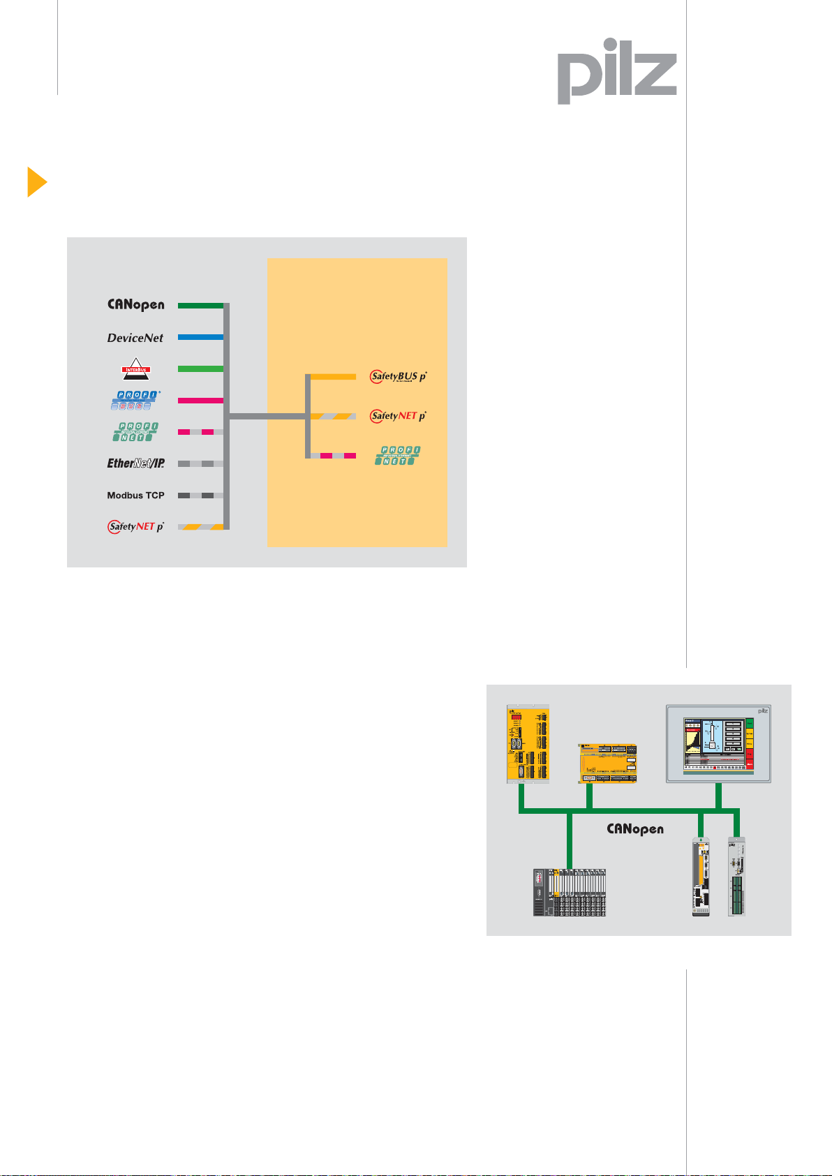
Ethernet interface ETH-2 –
Remote diagnostics
Lengthy travel times are now a
thing of the past. When servicing
is required, diagnostic data can
be accessed simply and quickly
from a remote location via the
ETH-2 Ethernet interface on
the PSS programmable safety
and control systems PSS
(PSS 3047-3 ETH-2,
PSS SB 3047-3 ETH-2 and
PSS SB 3075-3 ETH-2).
Complete networks can be
built up thanks to its master
functionality.
The complete solution for
your automation function
with CANopen
Combined with PSS
programmable safety and control
systems and other products with
CANopen interfaces, you now
have total fl exibility in your applications. Pilz offers a co-ordinated
solution comprising control
system, actuator technology
and visualisation.
Complete solution from Pilz with CANopen.
21
Page 24

Intelligent, future-proof control
Cost effectiveness
O
C
Safety
Control
A
U
T
O
PNOZmulti
Product group
PSS programmable safety and control systems
P
L
M
E
T
E
N
O
I
T
M
A
PSSmodular
systems
PSScompact
systems
PSS SB 3006-3 ETH-2
ST
F-STACK
FS
PG USER
R (USER)
PSS PWR
24 V
0 V
RUN ST
RUN FS
0 V
T 0
POWER
T 1
I0.0
AUTO PG
I0.1
SPS
I0.2
PG
I0.3
I0.4
RUN
I0.5
STOP
ETHERNET
LINK
10/100 BASE T
ON OFF
TRAFFIC
T
LINK
10/100 BASE T
TRAFFIC
SafetyBUS p
1
X0
3
1
X1
9
STATUS SB
Decentralised
periphery
PNOZelog
PNOZsigma
1 4 14 47 75 96 160 1 028 2 056 8 064
Complexity/number of safety functions
The appropriate solution – meeting your exact requirements: For simple plants with up to four safety functions,
safety relays PNOZ X, PNOZsigma or PNOZelog; for four safety functions and above, the PNOZmulti safety system;
for complex plant and machinery, PSS programmable safety and control systems.
Keep up-to-date on
PNOZ safety relays:
Webcode 0199
Online information
at www.pilz.com
The appropriate solution
for every requirement
With the extensive control
portfolio from Pilz you can cover
a wide range of applications.
PSS programmable safety and
control systems are the ideal
solution for safety-related and
standard control functions:
• For complex stand-alone
machines with high safety
requirements, such as presses
• For interlinked plants with
decentralised networking,
such as packaging machines
• For complete plant lines with
decentralised networking,
such as transfer lines
Intelligent, future-proof
investment
The complete solution from Pilz
is perfectly compatible. The
programmable safety and control
systems are subject to continuous
development, based on many
years of experience and in
constant consultation with
customers, guaranteeing longterm investment protection. Thus
they meet both current and future
requirements for safe, economical
automation solutions. In addition
to the PSS product group, the
Pilz portfolio also includes the
PNOZ product group, which
also stands for safe control.
22
Page 25

Standards for safety
Compliance with
international safety standards
Pilz’s thorough expertise in
safety technology pays off.
PSS programmable safety and
control systems meet the highest
safety requirements and therefore
comply with international standards for machine safety:
• EN 954-1 up to Category 4
• EN IEC 61508 up to SIL3
• EN IEC 62061 up to SIL3
• EN ISO 13849 up to PL e
• EN 60204-1
• NFPA 79
Represented in
various industries
The programmable safety
and control systems are easy to
use in the most wide-ranging
applications and industries.
They comply with various
application-specifi c standards.
Presses
EN 692,
EN 693,
EN 12622
Traffi c systems
EN 50126,
EN 50128,
EN 50129
each to SIL3,
EN 50159-1,
EN 50159-2
Cablecar
technology
EN 13243 AK4
PSS programmable safety and
control systems
are approved by
BG, TÜV and
UL/cUL.
Burner
management,
process technology
EN 289
Keep up-to-date
on laws and
standards:
Webcode 0240
Online information
at www.pilz.com
23
Page 26

O
C
Safety
Control
A
U
T
O
Product range
PSSmodular systems
PSSmodular systems
P
L
M
E
T
E
N
O
I
T
M
A
PSS 3000/PSS 3100
PSS 3000/PSS 3100
PSS 3000
and PSS 3100 –
Make your control
solution fl exible
and individual.
PSS 3000/PSS 3100
Two series covering
safety and control:
PSS 3000 and PSS 3100
The modular safety and control
systems PSS 3000 and PSS 3100
monitor safety-related functions
and perform standard control
functions at the same time:
Number of inputs/outputs
• Centrally – on complex,
independent stand-alone
machines, or
• Decentrally – on interlinked
plants extending over a
wide area
Communication interfaces to
fi eldbus systems, to the safe,
open bus system SafetyBUS p
and to Ethernet, enable the units
to be integrated quickly into the
plant’s full control sequence.
24
Page 27

Benefi ts at a glance
PSSmodular systems
When do I use which system?
The PSS 3000 modular system
is suitable for rugged application
conditions, e.g. for press controllers, fairground rides or in cablecars. All components feature
a sturdy aluminium housing
and can withstand increased
mechanical loads. In applications
requiring a large number of
standard inputs and outputs,
additional standard I/O modules
can be added to the PSS 3000
via 2 expansion module racks.
On the PSS 3100, the modules
are not enclosed in a housing
and the printed circuit boards
are visible, so they are suitable
for production environments with
low mechanical stress.
Modular hardware structure
Just assemble the hardware
components to match your own
individual project requirements:
• Module rack – with optional
integral power supply
• Central processing unit CPU –
with optional SafetyBUS p
connection
• Digital and analogue input/
output modules – for safetyrelated control functions
• Digital and analogue input/
output modules – for standard
control functions
• Communication modules
for all common fi eldbuses
and Ethernet
Your benefi ts at a glance
• One control system
for safety-related and
standard control functions
• Flexible and adaptable
thanks to the modular
hardware structure
• Highest performance
thanks to fast program
processing
• Wide range of application
areas thanks to digital and
analogue processing
• Open connection to
standard fi eldbuses,
Ethernet and SafetyBUS p
• Modules are simple and
quick to install
For decentralised
input/output,
use one system
for safety and
standard:
PSSuniversal –
Read more
from page 40.
Safety and control –
One system for all control
functions, e.g. on cablecars,
fairground rides, presses,
and many more
Keep up-to-date
on PSSmodular
systems:
Webcode 0911
Online information
at www.pilz.com
25
Page 28

Selection guide
PSSmodular systems
Selection guide – PSSmodular systems
Central processing units – PSSmodular controller
PSS 3000 series
Type
Order number
PSS CPU3 ............................................ 301 064 -
PSS SB CPU3 ...................................... 301 071 -
PSS SB CPU3 ETH-2 .......................... 301 081 -
- PSS1 CPU3 .......................................... 302 064
- PSS1 SB CPU3 .................................... 302 071
PSS1 SB CPU3
- PSS1 SB CPU3 ETH-2 ......................... 302 081
Module racks – PSSmodular controller
PSS 3000 series
Type
Order number
PSS BM 4 ............................................. 301 001 -
PSS BMP 4/2 ....................................... 301 006 -
PSS BM 8 ............................................. 301 000 -
PSS BMP 8 .......................................... 301 005 -
PSS 3100 series
Type
Order number
PSS 3100 series
Type
Order number
PSS1 BMPS 3/3
- PSS1 BMPS 3/3 ................................... 302 008
- PSS1 BMP 5/2 ..................................... 302 006
Power supplies – PSSmodular controller
PSS 3000 series
Type
Order number
PSS PS ................................................. 301 050 -
PSS PS 24 ............................................ 301 051 -
- PSS1 PS 24 .......................................... 302 051
PSS1 PS 24
PSS 3100 series
Type
Order number
26
Page 29

Features Communication
SafetyBUS p
• Data memory: Failsafe section: 64 KByte, standard section: 170 KByte
• Program memory:
Failsafe section: Integral 512 KByte Flash-EPROM memory,
Standard section: Integral 512 KByte Flash-EPROM memory
• Dimensions (H x W x D): 257 x 41 x 220 mm (PSS 3000), 265 x 41 x 218 mm (PSS 3100)
• Application range: Failsafe applications to EN 954-1, EN IEC 61508
• Interfaces:
Combined RS 232/RS 485 interface for programming device,
Combined RS 232/RS 485 interface as user interface
-
1
1
-
1
1
Electrical data
Free slots Size
(H x W x D)
Supply voltage
Number Use
- 4 For failsafe modules 277.5 x 280 x 244 mm
- 4 For failsafe modules,
277.5 x 280 x 244 mm
2 can be used for standard modules
- 9 For failsafe modules 277.5 x 482.6 x 244 mm
- 9 For failsafe and standard modules,
277.5 x 482.6 x 244 mm
plug in anywhere
24 VDC 3 For failsafe and standard modules,
266 x 259.4 x 245 mm
plug in anywhere, integral power supply
- 5 For failsafe modules,
2 can be used for standard modules
Electrical data
Supply voltage
Power consumption Continuous current
115/230 VAC, selectable 80 W 10 A
24 VDC 80 W 10 A
24 VDC 50 W 5 A
266 x 340.6 x 241 mm
Technical
documentation
on PSSmodular
systems:
Webcode 0685
Online information
at www.pilz.com
27
Page 30

Selection guide
PSSmodular systems
Selection guide – PSSmodular systems
Input/output modules for functional safety – PSSmodular I/O
PSS DI2O T
PSS1 DOR
PSS 3000 series
Type
Order number
PSS AI ....................301 121 PSS1 AI ..................302 121 - 6
PSS AI Ip ................301 123 PSS1 AI Ip ..............302 123 - -
PSS DI 2 .................301 101 PSS1 DI 2 ............... 302 101 32 -
PSS DIF ..................301 105 PSS1 DIF ................302 105 16 -
PSS DIF 2 ...............301 106 PSS1 DIF 2 .............302 106 16 -
PSS DI2O T ............301 112 PSS1 DI2O T .......... 302 112 16 -
PSS DI2O Z ............301 109 PSS DI2O Z ............302 109 16 -
PSS DOS ................301 111 PSS1 DOS ..............302 111 - -
PSS DOR ...............301 122 PSS1 DOR .............302 122 - -
PSS 3100 series
Type
Order number
Inputs
Digital
Common features:
• Application range: Failsafe applications to EN 954-1, EN IEC 61508
Inputs
Analogue
-10 V … +10 V
28
Input/output modules for standard applications – PSSmodular I/O
PSS 3000 series
Type
Order number
P10 AIO ..................304 120 P9 AIO ....................303 120 - 6
P10 DI ....................304 100 P9 DI ......................303 100 32 -
P10 DIO ..................304 107 - 16 -
- P9 DIO .................... 303 108 16 -
P10 DO ...................304 110 - - -
PSS DIO
- P9 DO .....................303 111 - -
P10 DOR 16 ...........304 122 P9 DOR 16 .............303 122 - -
PSS 3100 series
Type
Order number
Common features:
• Application range: Non-safety-related standard applications
Inputs
Digital
Inputs
Analogue
-10 V … +10 V
0 … 20 mA
Page 31

Outputs Features
4 … 20 mA Single-pole Dual-pole Relay
- - - - Analogue voltage inputs
6 - - - Analogue current inputs
1)
1)
- - - - Digital inputs to EN 954-1
up to Cat. 4 with test pulses
- - - - Digital inputs for alarms,
input delay 0.5 ms
- - - - Digital inputs for alarms,
input delay 3 ms
- 16 - - Digital inputs to EN 954-1 up to Cat. 4 with test pulses;
digital 2 A outputs, can also be used as test pulses
- - 8 - Digital inputs, dual-pole outputs (2 A)
- 32 - - Digital 1.5 A outputs
- - - 12 Relay outputs with positive-guided contacts
AC1: max. 250 V/0.1 … 4 A/1 000 VA
DC1: max. 250 V/0.4 A/100 W, 24 V/4 A/100 W
Outputs Features
Digital Analogue
-10 V … +10 V
Semi-
Relay 0 … 20 mA
conductor
- - 2 Analogue current/voltage inputs and outputs
- - - Digital inputs
16 - - Digital inputs, digital 2 A outputs
16 - - Digital inputs, digital 0.5 A outputs
32 - - Digital 2 A outputs
32 - - Digital 0.5 A outputs
Technical
documentation
on PSSmodular
systems:
Webcode 0685
Online information
at www.pilz.com
- 16 - Relay outputs
AC: max. 250 V/2 A/500 VA
DC: max. 100 V/0.5 A/50 W
1)
not for input/output modules for standard applications
29
Page 32

Selection guide
PSSmodular systems
Selection guide – PSSmodular systems
Communication modules for fi eldbus systems and Ethernet – PSSmodular COM
PSS ETH-2
PSS1 DN-S
PSS 3000 series
Type
Order number
PSS Ethernet ....................................... 301 157 PSS1 Ethernet ..................................... 302 157
PSS ETH-2 ........................................... 301 160 PSS1 ETH-2 ......................................... 302 160
PSS DP-S ............................................. 301 151 PSS1 DP-S ........................................... 302 151
PSS DN-S ............................................ 301 152 PSS1 DN-S .......................................... 302 152
PSS IBS-S PCP ................................... 301 154 PSS1 IBS-S PCP ................................. 302 154
PSS ControlNet Adapter .................... 301 156 PSS1 ControlNet-Adapter .................. 302 156
PSS CANopen ..................................... 301 155 PSS1 CANopen ................................... 302 155
PSS 3100 series
Type
Order number
PSS1 SER
PSS SER .............................................. 301 159 PSS1 SER ............................................ 302 159
30
Page 33

Function Features
Ethernet
Ethernet • Ethernet interfaces: Twisted Pair (RJ45)/AUI (IEEE 802.3)
Ethernet • Ethernet interfaces: Twisted Pair (RJ45)/4 Ports
PROFIBUS-DP • Device type: Slave
DeviceNet • Device type: Slave
Interbus • Device type: Slave with PCP channel
ControlNet • Device type: Adapter
CANopen • Device type: Slave
Serial interface • COM1/COM2: RS 232/RS 485 (combined)
• IP address: Selectable via confi guration software or DHCP
• Transmission rate: 10 MBit/s
• IP address: Selectable via confi guration software or DHCP
• Transmission rate: 10/100 MBit/s
• Transmission rate: 9.6/19.2/93.75/187.5/500 kBit/s, 1.5/3/6/12 MBit/s
• Data length: max. 488 Bytes
• Transmission rate: 125/250/500 kBit/s, selectable via rotary switch
• Data length: 0 ... 32 words, selectable
• Transmission rate: 500 kBit/s or 2 MBit/s, selectable
• Data length: 0 … 32 words, selectable (incl. PCP)
• PCP channel: 0, 1, 2 or 4 words, selectable
• ControlNet interface in accordance with ControlNet International
• Transmission rate: 5 MBit/s
• Data length: scheduled messages 0 … 128 words, unscheduled messages 32 words
• CANopen interface in accordance with CiA DS 301 V3.0 and CiA DS 102 V2.0
• Transmission rate: 6/10/12.5/20/33/50/66/100/125/333/500/666/1 000 kBit/s
• Data length: max. 512 Words
• Transmission rate: 150/300/600/1 200/2 400/4 800/9 600/19 200/38 400/57 600/76 800/115 200 Bit/s
• Data length: 1 024 Words
Technical
documentation
on PSSmodular
systems:
Webcode 0685
Online information
at www.pilz.com
31
Page 34

O
C
Safety
Control
A
U
T
O
Product range
PSScompact systems
PSScompact systems
P
L
M
E
T
E
N
O
I
T
M
A
PSS 3006 SB2
PSS 3006 SB
PSS 3075 SB
PSS 3047 SB
PSS 3075
PSS 3047
PSS SB 3006-3 ETH-2
RUN ST
RUN FS
POWER
AUTO PG
ST
F-STACK
RUN
FS
STOP
PG USER
ON OFF
R (USER)
T
PSS PWR
1
24 V
X0
0 V
3
0 V
1
T 0
T 1
I0.0
X1
I0.1
SPS
I0.2
PG
I0.3
I0.4
9
I0.5
ETHERNET
LINK
10/100 BASE T
TRAFFIC
LINK
10/100 BASE T
TRAFFIC
STATUS SB
SafetyBUS p
Choose the control
solution that’s right
for you from our
comprehensive
portfolio.
Numerous application options
Different projects require different
control solutions. PSScompact
systems are versatile, so you
always have the right solution –
whether on stand-alone machines
or extended plants.
Centralised control
of stand-alone machines
With a constant number of
sensors and actuators, the
PSScompact is the right
solution:
Number of inputs/outputs
• PSS 3047 – Centralised
system with 47 failsafe inputs
and outputs
• PSS 3075 – Centralised
system with 75 failsafe inputs
and outputs
Application examples:
Machining centres, presses
32
Page 35

Benefi ts at a glance
PSScompact systems
Centralised control with
optional decentralised
expansion via SafetyBUS p
Reduced wiring on large
stand-alone machines, so fl exible
when it comes to subsequent
changes and expansions:
• PSS 3047 SB – Centralised
system with 47 failsafe inputs
and outputs and decentralised
expansion options via
SafetyBUS p
• PSS 3075 SB – Centralised
system with 75 failsafe inputs
and outputs and decentralised
expansion options via
SafetyBUS p
Centrally driven stand-alone
machines can be interconnected
via SafetyBUS p in order to
exchange safety-related
information.
Application examples:
Press brakes, mechanical and
hydraulic presses, cable cars
Decentralised control
of extended plants via
SafetyBUS p
Create the optimum structure for
plant lines extending over a large
physical area and/or connect
independent machine units to
form interlinked plants:
• PSS 3006 SB –
Decentralised system with up
to 4,032 failsafe inputs and
outputs via SafetyBUS p
Application examples: Large
presses, packaging machines
Double the network
extension with SafetyBUS p
Network distributed plants with
network extensions of up to
7,000 metres through a second
SafetyBUS p interface:
• PSS 3006 SB2 – For up to
8,064 decentralised failsafe
inputs and outputs via
SafetyBUS p
Up to 126 bus subscribers can
be connected without problem.
Application examples:
Cablecar technology, press lines,
paint lines
Your benefi ts at a glance
• One control system for
safety-related and standard
control functions
• Open connection to
standard fi eldbuses,
Ethernet and SafetyBUS p
• Comprehensive product
portfolio for a wide
range of applications
• Rapid processing of time-
critical cycles and short
reaction times due to alarm
processing
Rugged and safe
With the rugged version of
the PSScompact systems
PSS 3047-3 AI Ip-R you can
comply with all the requirements
for vibration and shock. Even
with sinusoidal continuous duty
with sliding frequency in all
three spatial directions, vibration
resistance is guaranteed. Shock
resistance is also guaranteed
with up to 1,000 half sine shocks.
For decentralised
input/output,
use one system
for safety
and standard:
PSSuniversal –
Read more from
page 40.
Keep up-to-date
on PSScompact
systems:
Webcode 0914
Online information
at www.pilz.com
33
Page 36

Selection guide
PSScompact systems
Selection guide – PSScompact systems
Centralised safety system with 47 inputs/outputs – PSS 3047
PSS 3047-3
Type Inputs
Digital
(6 are alarm
outputs)
PSS 3047-3 32 - - 12
PSS 3047-3 DP-S 32 - - 12
PSS 3047-3 ETH-2 32 - - 12
PSS 3047-3 CANopen 32 - - 12
PSS 3047-3 AI 32 6 - 12
PSS 3047-3 AI Ip 32 - 6 12
PSS 3047-3 AI Ip-R 32 - 6 12
Inputs
Analogue
-10 V … +10 V 0 … 25.5 mA Single-pole
Outputs
(4 are
test pulse
outputs)
Centralised safety system with 47 inputs/outputs and decentralised expansion options via SafetyBUS p – PSS
Type Inputs
Digital
(6 are alarm
outputs)
Inputs
Analogue
-10 V … +10 V 0 … 25.5 mA Single-pole
Outputs
(4 are
test pulse
outputs)
34
PSS SB 3047-3 ETH-2
PSS SB 3047-3 ETH-2 32 - - 12
PSS SB 3047-3 DP-S 32 - - 12
PSS SB 3047-3 AI ETH-2 32 6 - 12
PSS SB 3047-3 AI Ip ETH-2 32 - 6 12
Common features:
• Supply voltage: 24 VDC
• Data memory: Failsafe section: 64 kByte,
standard section: 170 KByte
• Program memory:
Failsafe section: Integral 512 kByte
Flash-EPROM memory,
standard section: Integral 512 kByte
Flash-EPROM memory
• Application range:
Failsafe applications to
EN 954-1, EN IEC 61508
• Interfaces: Combined
RS 232/RS 485 interface for
programming device, combined
RS 232/RS 485 interface as
user interface
• Dimensions (H x W x D):
246.4 x see table x 162 mm
Page 37

Dual-pole
Communication Size Order
number
Width Screw terminals Spring-loaded
Accessories, connector sets
terminals
SafetyBUS p
3 87.0 mm 300 100 PSS ZKL 3047-3
3
3
3
3 123.6 mm 300 110 PSS ZKL 3047-3 AI
3 123.6 mm 300 115
3 138.6 mm 300 215
PROFIBUS-DP
CANopen
◆
◆
Ethernet
123.6 mm 300 105
123.6 mm 300 120
◆
123.6 mm 300 130
Order number:
300 900
Order number:
300 902
3047 SB
Dual-pole
3
3
3
3
Communication Size Order
Width Screw terminals Spring-loaded
SafetyBUS p
◆◆
◆◆
◆◆
◆◆
PROFIBUS-DP
CANopen
Ethernet
123.6 mm 300 150 PSS ZKL 3047-3
160.2 mm 300 160
160.2 mm 300 170 PSS ZKL 3047-3 AI
160.2 mm 300 180
number
Accessories, connector sets
Order number:
300 900
Order number:
300 902
PSS ZKF 3047-3
Order number:
300 904
PSS ZKF 3047-3 AI
Order number:
300 906
terminals
PSS ZKF 3047-3
Order number:
300 904
PSS ZKF 3047-3 AI
Order number:
300 906
Ethernet
Technical
documentation
on PSScompact
systems:
Webcode 0685
Online information
at www.pilz.com
35
Page 38

Selection guide
PSScompact systems
Selection guide – PSScompact systems
Centralised safety system with 75 inputs/outputs – PSS 3075
PSS 3075-3
Type Inputs
Digital
(6 are alarm
outputs)
PSS 3075-3 48 - - 18
PSS 3075-3 DP-S 48 - - 18
Inputs
Analogue
-10 V … +10 V 0 … 25.5 mA Single-pole
Outputs
(4 are
test pulse
outputs)
Centralised safety system with 75 inputs/outputs and decentralised expansion options via SafetyBUS p – PSS
Type Inputs
Digital
(6 are alarm
outputs)
Inputs
Analogue
-10 V … +10 V 0 … 25.5 mA Single-pole
Outputs
(4 are
test pulse
outputs)
36
PSS SB 3075-3 ETH-2
PSS SB 3075-3 CANopen 48 - - 18
PSS SB 3075-3 48 - - 18
PSS SB 3075-3 ETH-2 48 - - 18
PSS SB 3075-3 DP-S 48 - - 18
Common features:
• Supply voltage: 24 VDC
• Data memory: Failsafe section: 64 kByte,
standard section: 170 KByte
• Program memory:
Failsafe section: Integral 512 kByte
Flash-EPROM memory,
standard section: Integral 512 kByte
Flash-EPROM memory
• Application range:
Failsafe applications to
EN 954-1, EN IEC 61508
• Interfaces: Combined
RS 232/RS 485 interface for
programming device, combined
RS 232/RS 485 interface as
user interface
• Dimensions (H x W x D):
246.4 x see table x 162 mm
Page 39

Dual-pole
Communication Size Order
number
Width Screw terminals Spring-loaded
Accessories, connector sets
terminals
SafetyBUS p
9 123.6 mm 300 200 PSS ZKL 3075-3
9
PROFIBUS-DP
CANopen
◆
Ethernet
160.2 mm 300 205
Order number:
300 910
3075 SB
Dual-pole
9
9
9
Communication Size Order
Width Screw terminals Spring-loaded
SafetyBUS p
◆◆
◆
◆◆
PROFIBUS-DP
CANopen
Ethernet
196.8 mm 300 230 PSS ZKL 3075-3
160.2 mm 300 240
160.2 mm 300 250
number
Accessories, connector sets
Order number:
300 910
PSS ZKF 3075-3
Order number:
300 912
Ethernet
terminals
PSS ZKF 3075-3
Order number:
300 912
9
◆◆
196.8 mm 300 255
Technical
documentation
on PSScompact
systems:
Webcode 0685
Online information
at www.pilz.com
37
Page 40

Selection guide
PSScompact systems
Selection guide – PSScompact systems
Decentralised safety system with up to 4,032 inputs/outputs via SafetyBUS p – PSS 3006 SB
Common features:
Type Inputs
• Supply voltage: 24 VDC
• Data memory:
Failsafe section: 64 kByte,
standard section: 170 KByte
• Program memory:
Failsafe section: Integral 512 kByte
Flash-EPROM memory,
standard section: Integral 512 kByte
PSS SB 3006-3 ETH 6
PSS SB 3006-3 ETH-2 6
Flash-EPROM memory
• Dimensions (H x W x D):
246 x 123 x 161 mm
• Application range:
Failsafe applications to
EN 954-1, EN IEC 61508
• Interfaces: Combined
RS 232/RS 485 interface for
programming device, combined
RS 232/RS 485 interface as
user interface
PSS SB 3006-3 ETH-2
PSS SB 3006-3 DP-S 6
PSS SB 3006-3 IBS-S 6
PSS SB 3006-3 DN-S 6
PSS SB 3006-3 CN-A 6
PSS SB 3006-3 ETH DP-S 6
PSS SB 3006-3 ETH IBS-S 6
PSS SB 3006-3 ETH-2 IBS-S 6
PSS SB 3006-3 ETH-2 DP-S 6
Digital
Decentralised safety system with up to 8,064 inputs/outputs via SafetyBUS p – PSS 3006 SB2
Common features:
Type Inputs
• Supply voltage: 24 VDC
• Data memory:
Failsafe section: 64 kByte,
standard section: 170 KByte
• Program memory:
Failsafe section: Integral 512 kByte
Flash-EPROM memory,
standard section: Integral 512 kByte
PSS SB2 3006-3 DP-S 6
PSS SB2 3006-3 IBS-S 6
Flash-EPROM memory
• Dimensions (H x W x D):
246 x 123 x 161 mm
PSS SB2 3006-3 DN-S 6
PSS SB2 3006-3 CN-A 6
• Application range:
Failsafe applications to
EN 954-1, EN IEC 61508
PSS SB2 3006-3 ETH-2
PSS SB2 3006-3 ETH-2 6
PSS SB2 3006-3 ETH-2 DP-S 6
• Interfaces: Combined
RS 232/RS 485 interface for
PSS SB2 3006-3 ETH-2 IBS-S 6
programming device, combined
RS 232/RS 485 interface as
user interface
Digital
38
Page 41

Outputs Communication Order
number
Test pulses
Accessories, connector sets
Screw terminals Spring-loaded
terminals
SafetyBUS p
2
2
2
2
2
2
2
2
2
2
Outputs Communication Order
Test pulses
◆◆
◆◆
◆◆
◆◆
◆◆
◆◆
◆◆ ◆
◆◆ ◆
◆◆ ◆
◆◆ ◆
PROFIBUS-DP
Interbus
ControlNet
DeviceNet
Ethernet
301 630 PSS ZKL 3006-3
301 780
301 600
301 610
301 750
301 620
301 650
301 660
301 800
301 790
number
PSS ZKF 3006-3
Order number:
300 914
Accessories, connector sets
Screw terminals Spring-loaded
Order number:
300 916
terminals
Ethernet
SafetyBUS p
2
2
2
2
2
2
2
◆ (2 x) ◆
◆ (2 x) ◆
◆ (2 x) ◆
◆ (2 x) ◆
◆ (2 x) ◆
◆ (2 x) ◆◆
◆ (2 x) ◆◆
PROFIBUS-DP
Interbus
ControlNet
DeviceNet
Ethernet
301 680 PSS ZKL 3006-3
301 690
301 770
301 700
301 640
301 710
301 720
Order number:
300 914
PSS ZKF 3006-3
Order number:
300 916
Technical
documentation
on PSScompact
systems:
Webcode 0685
Online information
at www.pilz.com
39
Page 42

O
C
Safety
Control
A
U
T
O
Product ranges
Decentralised periphery and network components
Decentralised periphery and network com
P
L
M
E
T
E
N
O
I
T
M
A
Input/output on interlinked plants
extending over a wide area
Are you looking for a convincing
solution at fi eld level? Then Pilz’s
decentralised components are
an advised choice – whether you
are looking for a complete system
for the I/O periphery or an IP67
input module.
PSSuniversal – One system
for the whole I/O periphery
With the decentralised I/O system
PSSuniversal, safety-related and/
or standard control functions are
performed decentrally at fi eld
level. Communication at control
level is via common fi eldbus
systems and/or the safe, open
bus system SafetyBUS p.
Temperature-resistant modules
Rugged environments demand
components that will operate
reliably where there are high
temperature fl uctuations. Special
PSSuniversal modules, which
are identifi ed by a T in the type
description, can be used in
places where cabinet heating
would be very costly or uneconomical, or where heat is a key
factor. In a temperature range
of -30 °C to +60 °C they can
easily withstand moisture and
condensation within the scope
of pollution degree 2.
All sensor and actuator signals
are connected to one module.
So clear cabling is assured and
errors during installation can
be avoided.
40
Page 43

ponents
PSS67 – Resistant to dirt and water in accordance with IP67.
PSS67 – Input module
for cabinet-free installation
The digital input module PSS67
monitors safety functions decentrally in the fi eld. Both the module
and the M12 connections offer
IP67 protection. Simple screw
assembly minimises your planning, design and installation
work. Direct on-site installation
also saves you space in the
control cabinet. Thanks to the
extended temperature range
of -40 °C to +60 °C, you can now
be fl exible in your applications.
Network components –
For a clear, powerful network
Network components make
extended plants with distributed
control logic more powerful.
Network components enable:
• The bus architectures to
be clearly structured
• The networks to be divided
into individual bus segments
• Several networks to be
linked together
Router Bridge Active Junction
Components for
SafetyBUS p networks:
• Router – Logical division
of your bus structure, particularly when the individual bus
subscribers are physically
separated over a long distance.
• Bridge – The link to rapid
data transfer, to an increase in
the number of bus subscribers
and to the network’s maximum
overall length.
• Active Junction –
Modular, fl exible isolation
of sub branches
Keep up-to-date on:
• Decentralised
periphery
Webcode 0930
• Network
components
Webcode 0934
Online information
at www.pilz.com
41
Page 44

O
C
Safety
Control
A
U
T
O
Product range
Decentralised I/O system PSSuniversal
Decentralised I/O system PSSuniversal
P
L
M
E
T
E
N
O
I
T
M
A
Standard
Modular system structure
Assemble the input and output
modules on the decentralised
I/O system individually in accordance with your requirements and
adapt the system structure of the
PSSuniversal modules to meet
your exact needs. When adjustments are made to the system
at a later date, simply add new
modules or exchange existing
ones.
1
Head module
Connects the sensor/actuator
level to master control systems
via SafetyBUS p for safetyrelated functions and/or standard
fi eldbus systems for standard
control functions.
2
Input/output modules
For safety-related or non-safetyrelated digital or analogue signal
processing. Up to 64 input/output
modules can be installed in
any order.
3
Supply voltage module
For the internal supply voltage
and the formation of different
supply groups.
4
Safe block
switching module
For the formation of safe shutdown
groups on the hardware side.
Failsafe
5
Base modules
Carrier units for the input/output
modules, the supply voltage
modules and the block switching
module. These are simply
inserted on to the base modules
and are easy to change when
adjustments are made to the
system.
3
1
42
Page 45

1. The head module is attached
to the top hat rail.
2. The relevant base modules
are attached to the top hat rail.
3. The modules are attached
and connected.
4. The terminating plate is attached
with an end bracket.
2
5
5. With just one click: the relevant
electronic modules are connected.
4
2
5
5
6. The modules are labelled.
5
PSSuniversal –
The future-proof I/O system
for safety and standard.
Module selection
made simple – with
the PSSuniversal
Assistant:
Webcode 1250
Online information
at www.pilz.com
43
Page 46

Product range
Decentralised I/O system PSSuniversal
PSSuniversal – The future-proof I/O solution
Intelligent dovetailing
of standard and safety
On the decentralised I/O system
PSSuniversal, safety-related and
standard control functions are
mixed in physical terms, but
separate in terms of logic. The
requirements for extremely short
reaction times and absence of
feedback can therefore be met.
The system is designed completely in accordance with
Category 4 of EN 954-1 and
SIL3 of IEC 61508.
Sheer diversity
The PSSuniversal has various
head modules, so you can
operate fl exibly to suit your
requirements. The failsafe head
modules are equipped with
interfaces to common communication networks such as CANopen,
DeviceNET, PROFIBUS,
PROFINET, INTERBUS and
SafetyBUS p; the standard
head modules can communicate
with CANopen, DeviceNET,
PROFIBUS, PROFINET and
INTERBUS. This means you
can retain your existing system
architectures.
Local enable principle
reduces response times
The local enable principle on
the PSSuniversal compares the
incoming switch signals from the
process controller at fi eld level
with the safe enable information
on the PSS system. It then
enables the signals when
safe operation of the plant is
guaranteed.
By shifting the enable principle
to fi eld level, reduced demands
are placed on the system in
terms of CPU cycle time and bus
transmission time. Comparative
measurements have shown that
this can reduce actual response
times by more than 60 %.
Standard Failsafe
The local enable principle guarantees
the safe operationa of your plant.
44
Page 47

Benefi ts at a glance
Decentralised I/O system PSSuniversal
Rapid commissioning
The PSSuniversal Startup
Software can be used to carry
out initial cable and function
tests before the plant or machine
is assembled. That way all of the
periphery is tested and functional
when you come to commission
the control software. So commissioning work can be carried out
independently and in parallel,
reducing dependencies and
saving time.
Cable and function tests
are simply run through the
USB port on the notebook.
Your benefi ts at a glance
• Input/output of safety-
related and standard
control signals
• Modular system structure
for fl exible applications
• Extensive selection of
modules to meet your
requirements
• Digital and analogue
processing
• Response times reduced
by over 60 % thanks to the
local enable principle
• Optimum availability thanks
to safe block switching
• Rapid installation,
rapid module exchange
• Rapid commissioning
due to the independent
periphery test
Safe block switching
of individual plant sections
Block switching is used to shut
down the supply voltage to a
group of standard outputs (e.g.
several motors) when a hazardous event occurs. So when a
hazardous event does occur –
e.g. an E-STOP pushbutton is
operated – the safe shutdown
of a complete plant section is
guaranteed, while other sections
can continue to operate.
Standard
I/Os
When a fault occurs, safe block switching guarantees that a particular plant
section is shut down safely, while other sections can continue to operate.
Block
switching
Failsafe
I/Os
Keep up-to-date
on decentralised
periphery:
Webcode 0930
Online information
at www.pilz.com
45
Page 48

Selection guide
Decentralised I/O system PSSuniversal
Selection guide – Decentralised I/O system
Head modules for functional safety and standard control functions – PSSuniversal COM
Type Application range Communications interfaces
PSSu H SB DP
PSSu H DP
PSSu H SB
PSSu H SB DP
PSSu H SB DN
PSSu H SB CAN
PSSu H CAN
PSSu H DP
PSSu H DN
PSSu H SB IBSe
PSSu H SB IBSo
PSSu H IBSe
PSSu H IBSo
PSSu H F PN
PSSu H S PN
Failsafe functions
◆◆
◆◆◆ ◆
◆◆◆ ◆
◆◆◆ ◆
◆◆◆
◆◆◆
◆◆
Standard functions
◆◆
◆◆
◆◆
◆
◆
◆
SafetyBUS p
CANopen
DeviceNet
PROFIBUS-DP
46
Page 49

PSSuniversal
Size Order number
Interbus
◆
◆
◆
◆
PROIFNET
◆
H x W x D
128.4 x 50.2 x 72.6 mm 312 010 314 010
128.4 x 75.2 x 79.4 mm 312 025 314 025
128.4 x 75.2 x 79.4 mm 312 030 314 030
128.4 x 75.2 x 79.4 mm 312 035 314 035
128.4 x 75.2 x 79.4 mm 312 045 -
128.4 x 75.2 x 79.4 mm 312 046 314 045
128.4 x 75.2 x 79.4 mm 312 047 -
128.4 x 75.2 x 79.4 mm 312 015 -
128.4 x 75.2 x 79.4 mm 312 020 -
128.4 x 75.2 x 79.4 mm 312 048 -
128.4 x 75.2 x 79.4 mm 312 049 -
128.4 x 75.2 x 79.4 mm 312 040 -
Regular version Coated version
◆
128.4 x 75.2 x 79.4 mm 312 041 -
Technical
documentation
on the decentralised periphery:
Webcode 0685
Online information
at www.pilz.com
47
Page 50

Selection guide
Decentralised I/O system PSSuniversal
Selection guide – Decentralised I/O system
Supply modules, junction modules and safe block switching module – PSSuniversal I/O
PSSu E F PS
Type Function Application
PSSu E F PS Power supply
PSSu E F PS1 Power supply,
buffered
PSSu E F PS-P Power supply,
periphery
PSSu E PD Voltage
distribution
PSSu E PD1 Voltage
distribution
PSSu E F BSW Block switching
function
range
Failsafe functions
◆◆
◆◆
◆◆
◆◆
Electrical data
Supply
voltage
Standard functions
24 VDC max. 1.5 A
24 VDC max. 2.0 A
24 VDC -
--
◆
--
◆
24 VDC -
Current load
capacity
Module
supply
PSSu E PD
PSSu E PS-P 5 V Voltage
distribution
PSSu E PS-P +/- 10 V Voltage
distribution
PSSu E PS-P +/- 15 V Voltage
distribution
24 VDC -
◆
24 VDC -
◆
24 VDC -
◆
48
Page 51

PSSuniversal
Order number Screw terminals Cage clamp terminals
Current load
capacity
Periphery
supply
max. 10 A 312 190 314 190
max. 10 A 312 191 314 191
max. 10 A 312 185 314 185
- 312 195 314 195
- 312 196 314 196
max. 8 A 312 230 314 230
- 312 590 -
Regular
version
Coated
version
Order
number
........ 312 610
2)
............ 312 600
1)
PSSu BP-C 1/8 S
PSSu BP-C1 1/12 S ...... 312 618
PSSu BP-C 1/12 S ........ 312 622
PSSu BP-C 2/16 S ........ 312 630
PSSu BS 1/8 S .............. 312 650
PSSu BS-R 1/8 S .......... 312 652
PSSu BS-R 2/8 S .......... 312 654
Suitable
base module
PSSu BP 1/8 S
◆◆ ◆◆
◆◆
◆◆◆◆ ◆◆◆◆
◆◆◆
◆◆◆ ◆◆◆
PSSu BS 2/8 S .............. 312 656
◆◆ ◆◆
◆◆
........ 312 611
2)
............ 312 601
1)
PSSu BP 1/8 C
PSSu BP-C 1/8 C
PSSu BP-C 1/12 C ....... 312 619
PSSu BP-C1 1/12 C ..... 312 623
PSSu BP-C 2/16 C ....... 312 631
PSSu BS 1/8 C ............. 312 651
PSSu BS-R 1/8 C ......... 312 653
PSSu BS-R 2/8 C ......... 312 655
PSSu BS 2/8 C ............. 312 657
- 312 591 -
- 312 592 -
◆◆◆ ◆◆◆
◆◆◆ ◆◆◆
1)
without C-rail 2) with C-rail
Technical
documentation
on the decentralised periphery:
Webcode 0685
Online information
at www.pilz.com
49
Page 52

Selection guide
Decentralised I/O system PSSuniversal
Selection guide – Decentralised I/O system
Input/output modules for functional safety and standard control functions – PSSuniversal I/O
PSSu E S 4DI
Type Function Application
range
Failsafe functions
PSSu E S 4DI Digital inputs
PSSu E S 4DO 0.5 Digital outputs
PSSu E S 2DO 2 Digital outputs
PSSu E S 2DOR 10 Relay outputs
PSSu E S 2AI U Analogue inputs
PSSu E S 4AI U Analogue inputs
PSSu E S 2AI I se Analogue inputs
PSSu E S 2AI RTD Analogue inputs
PSSu E S 2AO U Analogue outputs
Standard functions
◆
◆
◆
◆
◆
◆
◆
◆
◆
Electrical data
Number of
inputs (value)
4
-
-
-
2 (0 … 10 V s.e.;
diff.; -10 … +10 V)
4 (0 … 10 V s.e.)
2 (0 … 20 mA; 4 … 20 mA)
2
-
PSSu E F 4DI
PSSu E F 2DOR 8
PSSu E F BSW
PSSu E S 4AO U Analogue outputs
PSSu E S 2AO I Analogue outputs
PSSu E S ABS SSI Absolute encoder SSI
PSSu E S INC Incremental encoder
PSSu E F 4DI Digital inputs
PSSu E F 4DO 0.5 Digital outputs
PSSu E F 2DO 2 Digital outputs
PSSu E F DI OZ 2 Digital outputs
PSSu E F 2DOR 8 Relay outputs
PSSu E F BSW Safe
Block switching
Common features:
• Supply voltage from module supply: 5 VDC
• Separation of supply
◆
◆
◆
◆
◆
◆
◆
◆
◆
◆◆
-
-
1 (SSI)
1 (INC)
4
-
-
1 (feedback loop)
-
-
50
Page 53

PSSuniversal
Order number Screw terminals Cage clamp terminals
Number of
outputs (value)
Regular
version
Coated
version
- 312 400 314 400
4 (0.5 A) 312 405 314 405
2 (2 A) 312 410 314 410
2 N/O 312 510 314 510
- 312 440 314 440
- 312 445 314 445
- 312 450 314 450
- 312 490 314 490
2 (0 … 10 V; -10 … +10 V) 312 460 314 460
4 (0 … 10 V) 312 465 314 465
600
610
618
620
622
630
656
601
Order
number
........ 312
1)
PSSu BP 1/8 S
Suitable
base module
.... 312
2)
...... 312
2)
PSSu BP-C 1/8 S
PSSu BP 1/12 S
PSSu BP-C 1/12 S .... 312
PSSu BP-C 1/12 S .... 312
PSSu BP-C 2/16 S .... 312
PSSu BS 2/8 S .......... 312
611
.... 312
2)
........ 312
1)
PSSu BP 1/8 C
PSSu BP-C 1/8 C
◆◆◆ ◆ ◆◆◆ ◆
◆◆◆ ◆ ◆◆◆ ◆
◆◆◆ ◆ ◆◆◆ ◆
◆◆
◆◆◆◆ ◆◆◆◆
◆◆◆◆ ◆◆◆◆
◆◆◆◆ ◆◆◆◆
◆◆ ◆◆
◆◆◆◆ ◆◆◆◆
◆◆◆◆ ◆◆◆◆
619
621
PSSu BP-C 1/12 C ... 312
623
PSSu BP-C 1/12 C ... 312
...... 312
2)
PSSu BP 1/12 C
631
PSSu BP-C 2/16 C ... 312
657
PSSu BS 2/8 C ......... 312
2 (0 … 20 mA; 4 … 20 mA) 312 470 314 470
- 312 480 314 480
- 312 485 314 485
2 test pulse outputs 312 200 314 200
4 (0.5 A) 312 210 314 210
2 (2 A) 312 215 314 215
1 (2 A), dual-pole
312 220 314 220
1 test pulse output
2 N/O
AC1: 250 V/8 A; 2
000 VA
312 225 314 225
DC1: 24 V/ 8 A; 192 W
- 312 230 314 230
◆◆◆◆ ◆◆◆◆
◆◆◆ ◆ ◆◆◆ ◆
◆◆
◆◆◆ ◆◆◆
◆◆ ◆◆
◆◆◆ ◆ ◆◆◆ ◆
◆◆◆ ◆ ◆◆◆ ◆
◆◆
◆◆
1)
without C-rail 2) with C-rail
Technical
documentation
on the decentralised periphery:
Webcode 0685
Online information
at www.pilz.com
51
Page 54

Selection guide
Decentralised I/O system PSSuniversal
Selection guide – Decentralised I/O system,
Wireless components – Remote station and base station for signal transfer via InduraNET p
Type Function
PSSu WB S IDN Base station with antenna connection
PSSu WB S IDN Remote station with antenna connection
PSSu WB S IDN
Wireless components – InduraNET p antennas and base modules
PSS ANT 1 IDN
Common features:
• Wireless communication: Frequency range 2.4 GHz ISM band
Type Function
PSS ANT 1 IDN InduraNET p single antenna with 2 m cable
PSS ANT 2 IDN InduraNET p dual antenna with 2 m cable
PSSu BP-C 2/16 S Base module with C-rail and screw terminals
PSSu BP-C 2/16 C Base module with C-rail and cage clamp terminals
PSSu BP 2/16 S Base module without C-rail with screw terminals
52
PSSu BP 2/16 C Base module without C-rail with cage clamp terminals
Page 55

wireless components
Application range Dimensions (H x W x D) Order number
Standard function 76 x 25.4 x 60.2 mm 312 095
Standard function 128.4 x 75.2 x 79.4 mm 312 096
Application range Order number
Standard function 312 995
Standard function 312 996
Standard function 312 630
Standard function 312 631
Standard function 312 628
Standard function 312 629
Technical
documentation
on the decentralised periphery:
Webcode 0685
Online information
at www.pilz.com
53
Page 56

Selection guide
Network components
Selection guide – Network components
Network components for SafetyBUS p
Router – Logical division
of your bus architecture
• Galvanic isolation
via optocoupler
Bridge – The link between
two networks for rapid
data transfer
• Galvanic isolation
via optocoupler
Active Junction – Modular,
fl exible isolation of sub branches
• Galvanic isolation between the
SafetyBUS p main branch and the
sub branches via optocoupler
• Max. 3 A load current
per sub branch, electronic short
circuit protection
• Main branch:
Female D-SUB connector (9-pin)
• Sub branches:
4-pin screw connectors
PSS SB BRIDGE
PSS SB ACTIVE
JUNCTION BASIS
Type Function
PSS SB Router1 Segmentation
PSS SB BRIDGE Coupling device
PSS SB ACTIVE
JUNCTION BASIS
PSS SB ACTIVE
JUNCTION EXPANSION
for SafetyBUS p
for SafetyBUS p
Active Y-junction with
repeater function –
Active Junction for
SafetyBUS p
Expansion module
for Active Junction for
SafetyBUS p
54
Active Junction Expansion –
Expansion module for
Active Junction
• Galvanic isolation between the
SafetyBUS p main branch and the
sub branches via optocoupler
• Max. 3 A load current
per sub branch, electronic short
circuit protection
• Sub branches:
4-pin screw connectors
Page 57

Electrical data SafetyBUS p Size
(H x W x D)
Galvanic
isolation
Subbranches
Virtual
cable runs
Connection Data width
Order
number
◆
- - 2 female
- 140 x 170 x 50 mm 311 055
D-SUB
connectors
(9-pin)
◆
- - 2 female
D-SUB
connector
(9-pin)
32 Bit as
virtual input/
outputs
(per SafetyBUS p
140 x 170 x 50 mm 301 131
network)
◆
2 50 m 1 female
- 94 x 49.2 x 126 mm 311 056
D-SUB
connector
(9-pin)
◆
2 - - - 94 x 26.5 x 121 mm 311 057
Technical
documentation
on network
components:
Webcode 0685
Online information
at www.pilz.com
55
Page 58

®
Selection guide – SafetyBUS p
Bus connector for SafetyBUS p
Type
PSS SB SUB-D4
accessories
Selection guide
SafetyBUS p
PSS SB SUB-D4
PSS SB SUB-D4 DIAG
Bus cable for SafetyBUS p
PSS SB
BUSCABLE0 MOVE
PSS SB SUB-D4 DIAG
PSS SB SUB-D-F01
Type Application range
PSS SB BUSCABLE0
PSS SB BUSCABLE0 MOVE
PSS SB BUSCABLE0 LC
Data transfer Supply for fi eld devices
◆
◆
◆◆
56
PSS SB BUSCABLE0 HC
Network tester for SafetyBUS p
Type Application range
PSS SB TESTER Network tester
PSS SB TESTER
◆◆
for SafetyBUS p
Page 59

Features Order
number
• Connector for SafetyBUS p
311 040
• Dimensions (H x W x D): 81 x 47 x 16 mm
• Female D-SUB connector, 9-pin
• Connection for permitted cable types PSS SB BUSCABLE0 and PSS SB BUSCABLE0 MOVE:
IDC terminals, cable diameter: 7.6 … 8.2 mm
• Single-core cross section: max. 0.75 mm
2
• Connector for SafetyBUS p
• Dimensions (H x W x D): 81 x 47 x 16 mm
• Female D-SUB connector, 9-pin
• Male D-SUB connector (diagnostics), 9-pin
• Connection for permitted cable types PSS SB BUSCABLE0 and PSS SB BUSCABLE0 MOVE:
IDC terminals, cable diameter: 7.6 … 8.2 mm
• Single-core cross section: max. 0.75 mm
2
• Fibre-optic coupler for SafetyBUS p
• Dimensions (H x W x D): 84 x 48 x 16 mm
• Female D-SUB connector, 9-pin
• Fibre-optic cable, ST connection for transmitter and receiver
• Graded index glass fi bre 50/125 μm or 62.5/125 μm
• Eye safety: Laser Class 3a
• Supply voltage: 5 VDC through the bus subscriber’s SafetyBUS p interface
Fixed installation Plug connection Mobile installation Field installation
◆◆
◆◆
◆ ◆
◆ ◆
311 041
311 053
Wires Order
number
3 311 070
3 311 071
1)
4
1)
4
311 074
311 076
Features Order number
• Power supply: Ni-Cd battery, 4.8 VDC, 1,000 mAh
• Charger: 110/230 VAC, 50 Hz
• Display type: Single-colour graphic LC display
German ................. 311 090
English .................. 311 091
French .................. 311 092
• Resolution: 128 x 64 pixels
• Interfaces: SafetyBUS p, USB
• Dimensions (H x W x D): 232 x 97 x 52 mm
1)
plus shielding
57
Page 60

Selection guide
PSS67
Selection guide – Input module PSS67 and
PSS67 – Module
PSS67 F 16DI SB-T
PSS67 – Cable
PSS67 Cable
Type Function Application range Number
Failsafe
functions
PSS67 F 16DI SB-T Digital inputs
Type Function Socket
PSS67 Cable M8sf M12sm Sensor cable M8
PSS67 Cable M8af M12sm Sensor cable M8
PSS67 Cable M12sf M12sm Sensor cable M12
PSS67 Cable M12af M12am Sensor cable M12
PSS67 Supply Cable IN sf OUT sm, B Supply cable -
PSS67 Supply Cable IN af OUT am, B Supply cable -
PSS67 Supply Cable IN sf, B Supply cable -
◆
Standard
functions
of inputs
(value)
16
PSS67 – Adapter
PSS67 Adapter
PSS67 Supply Cable IN af, B Supply cable -
PSS67 SB LC Cable IN sf OUT sm, A SafetyBUS p cable -
PSS67 SB LC Cable IN af OUT am, A SafetyBUS p cable -
PSS67 SB LC Cable IN sf, A SafetyBUS p cable -
PSS67 SB LC Cable IN af, A SafetyBUS p cable -
Type
PSEN mag ad
PSEN cs ad
PSEN op1.1 ad
PSEN op1.2 ad
PSEN M8 M12 Transmitter ad
PSEN op 2H Receiver ad
PSEN op M12 V1 Receiver ad
PSEN op M12 V1 Receiver ad
PSEN T M12
58
Page 61

accessories
Number of test
pulse outputs
(value)
4 1 -40 °C … +60 °C 24 VDC 215 x 60 x 35.5 mm 311 300
Connector Order number
M12 380 200 380 201 380 202 380 203
M12 380 204 380 205 380 206 380 207
M12 380 208 380 209 380 210 380 211
M12 380 212 380 213 380 214 380 215
- 380 250 380 251 380 252 -
- 380 253 380 254 380 255 -
- 380 256 380 257 380 258 -
Communications
interfaces
SafetyBUS p
interfaces
3 m length 5 m length 10 m length 30 m length
Ambient
temperature
Supply voltage Dimensions
(H x W x D)
Order
number
- 380 259 380 260 380 261 -
- 380 500 380 501 380 502 -
- 380 503 380 504 380 505 -
- 380 506 380 507 380 508 -
- 380 509 380 510 380 511 -
Application range Order number
Adapter for connection to PSENmag 380 300
Adapter for connection to PSENcode 380 301
Adapter for connection to PSEN op1.1 and PSEN op1.3 380 302
Adapter for connection to PSEN op1.2 380 303
Adapter for connection to PSEN op4F-s, PSEN op4H-s, PSEN op4F-m, PSEN op4H-m transmitter 380 304
Adapter for connection to PSEN op2H receiver 380 305
Adapter for connection to PSEN op4F-s, PSEN op4H-s, PSEN op4F-m, PSEN op4H-m receiver 380 306
Adapter for connection to PSEN op2B, PSEN op4F, PSEN op4H, PSEN op4B receiver 380 307
T-Adapter for connection to 2 PSEN 380 350
59
Page 62

Product range
PSENopt SB for SafetyBUS p
The complete
one-stop solution:
PSEN safe sensors
from Pilz!
Webcode 0219
Online information
at www.pilz.com
Light curtains and light grids for SafetyBUS p
®
Safety for man and machine
Safeguard danger zones,
protect man, machine and
capital goods. Safely, effectively
and economically with Pilz light
curtains and light grids.
As they are non-wearing and
have fast access times, light
curtains and light grids are
particularly suitable for numerous
applications and industries.
For example:
• Metal and sheet metal working
• Robot systems
and assembly lines
• Transport and conveyor
systems
• Food and packaging machinery
Simpler installation,
fewer components
Light grids with an integrated bus
interface are particularly suitable
for use in distributed plants or
in cramped conditions. All the
settings relating to the light
grid can be stored centrally
on the PSS system and can be
activated via the safe bus system
SafetyBUS p. There is no need
for any external components
such as an evaluation device or
service distribution system.
Diagnostics make
all the difference
Diagnostics are much more
detailed via a light grid with an
integrated SafetyBUS p interface:
In addition to purely functional
and wiring-related diagnostics,
information such as misalignment,
contamination signal, external
light source, supply voltage
status for the transmitter/receiver
etc. can be sent to the PSS
programmable safety and control
systems. As part of preventive
maintenance, this diagnostic
data helps to detect faults early,
before they potentially cause the
plant or machine to shut down.
Your benefi ts at a glance
• Less project confi guration
work as there are fewer
components
• Less work during
installation, reduced
space requirement
• Reduced downtimes during
operation thanks to simple
troubleshooting and comprehensive diagnostic data
• Complete solution that's
safe and approved
60
Page 63

Selection guide
PSENopt SB for SafetyBUS p
Selection guide – PSENopt for SafetyBUS p
®
Light curtains and light grids for SafetyBUS p – PSENopt SB
Type Function Optical data Order number
PSEN opSB-4F
PSEN opSB-4H
PSEN opSB-4F Finger
protection
for SafetyBUS p
Resolution:
14 mm
PSEN opSB-4H Hand protection
for SafetyBUS p
Resolution:
30 mm
Operating
range
0.2 … 6 m 300 … 900 mm • PSEN opSB-
0.2 … 15 m 300 … 1 650 mm • PSEN opSB-
Height of
protected fi eld
4F-14-030 ....... 630 351
• PSEN opSB-
4F-14-045 ....... 630 352
• PSEN opSB-
4F-14-060 ....... 630 353
• PSEN opSB-
4F-14-075 ....... 630 354
• PSEN opSB-
4F-14-090 ....... 630 355
4H-30-030 ......630 451
• PSEN opSB-
4H-30-045 ......630 452
• PSEN opSB-
4H-30-060 ......630 453
• PSEN opSB-
4H-30-075 ......630 454
• PSEN opSB-
4H-30-090 ......630 455
• PSEN opSB-
4H-30-105 ......630 456
• PSEN opSB-
4H-30-120 ......630 457
• PSEN opSB-
4H-30-135 ......630 458
• PSEN opSB-
4H-30-150 ......630 459
• PSEN opSB-
4H-30-165 ......630 460
PSEN opSB-4B
PSEN opSB-4B Body protection
for SafetyBUS p
2, 3 or
4 beams
0.5 … 25 m 500 … 1 200 mm • PSEN opSB-
Common features:
• Compliant and approved in accordance
with DIN VDE 080 and EN IEC 61508
• Approved in accordance with
EN IEC 61496-1/-2: Type 4
• Can be used in applications in accordance
with Category 4 of EN 954-1 for fi nger,
hand and body protection
• Integral functions: Muting (total/partial)
4B-2-050 ........630 550
• PSEN opSB-
4B-3-080 ........630 551
• PSEN opSB-
4B-4-090 ........630 552
• PSEN opSB-
4B-4-120 ........630 553
• Integral SafetyBUS p interface
• Connection:
Receiver Rx: M12, 8-pin and 5-pin;
Transmitter Tx: M12, 4-pin
• Supply voltage: 24 VDC
• Dimensions (in mm):
40 x 35 x Length
61
Page 64

PSS system software
Product range
System software
Solutions for the whole
engineering process
Practical software solutions are
available when designing and
programming PSS safety and
control systems – providing
support from planning to
diagnostics.
System software
PSS WIN-PRO offers
a wide function range
• Copy function – existing plant
projects can be transferred
into new projects
• Block encryption – to protect
against manipulation and
unauthorised access
• Language switching –
for worldwide use
• Online handling – which makes
troubleshooting easier in the
test and commissioning phase
PSS WIN-PRO as
full version or service version
PSS WIN-PRO is available as a
full version and a service version.
The full version contains the PVIS
diagnostic concept, with which
you can quickly and easily integrate unique plain text messages,
location information and stepby-step instructions into your
diagnostics.
The service version can be
used to evaluate maintenance
and diagnostic information.
Further information on PVIS
can be found on page 68.
PSS WIN-PRO –
Universal system software
with practical tools
PSS WIN-PRO contains
practical add-on tools to make
confi guration easier:
• PSSuniversal Startup
Software – including the
PSSuniversal Assistant for
confi guration and for the
independent periphery test of
the decentralised I/O system
PSSuniversal
• SafetyBUS p Confi gurator –
for confi guration of the safe
bus system SafetyBUS p
• Ethernet Confi gurator –
for setting up complete
Ethernet networks
The add-on tools are also
available separately.
62
Page 65

Benefi ts at a glance
System software
Your benefi ts at a glance
• PSS WIN-PRO
available as full version
and service version
• Practical add-on tools
for rapid confi guration of
the whole control solution
• Copy function for
existing plant projects
• Extensive selection of
software function blocks
• Manipulation protection
through block encryption
• Integrated PVIS diagnostic
concept
Simple to program thanks
to software function blocks
With an extensive selection
of software function blocks for
safety and control, we make
it easier for you to program
standardised control sequences.
Instead of complex programming
you just have to set the parameters – and that requires a lot
less effort!
Software function blocks
for the plant’s safety-related
section:
• To control and monitor
presses, transfer lines,
general E-STOP, safety
gate and light grid functions
• To enter plant-specifi c
parameters
• Approved by BG and TÜV
Software function blocks
for the plant’s standard section:
• Can be integrated into existing
fi eldbus and Ethernet networks
via the relevant drivers
• Direct connection via
communication modules
or user interfaces
An overview of the function
blocks can be found on page 66.
Keep up-to-date
on system software:
Webcode 1531
Online information
at www.pilz.com
63
Page 66

Selection guide
System software
Selection guide – System software
System software and confi guration tools for PSS programmable safety and control systems
Type Features
PSS WIN-PRO CD
System software
• Programming software PSS WIN-PRO
• Windows-based user interface:
German, English, French, Spanish (selectable)
• Programming languages: IL, LD, FBD (selectable)
• Online help
• Also contains:
- PSSuniversal Assistant confi guration software
- PSSuniversal Startup Software
- Ethernet Confi gurator
- SafetyBUS p Confi gurator
- Diagnostic concept PVIS
PSSuniversal Startup Software
incl. PSSuniversal Assistant
Confi guration and independent
periphery test of the decentralised
I/O system PSSuniversal
PVIS OPC Server,
PVIS ActiveX Control,
PVIS OPC Confi gurator
Diagnostic software
• Function test performed on a PSSuniversal
system via the integral USB port, without
the controller connected
• FS and ST outputs are switched on/off
• Input status display
(supports the panel builder, for example,
during the wiring test)
• Online help
• Diagnostics displayed on Pilz operator terminals PMIvisu,
PMIopen or industrial computers, in accordance
with the Pilz PVIS diagnostic concept
• The triggering fault is displayed along with
step-by-step remedy information for the operator
• Diagnostic texts and remedies are created simply
by selecting from the list of ready-made texts in
PSS WIN-PRO
• Diagnostic data is called up from the control
system through PVIS ActiveX Control or other OPC Clients
• Process data is called up from the control system
through other OPC Clients (e.g. graphics software)
• PVIS OPC Server is confi gured via the
PVIS OPC Confi gurator
64
Planning and product selection guides
Pilz Service Applications CD
2D and 3D product macros
for EPLAN 5.70 and eCabinet
• User interface: German and English
Page 67

System requirements Order number
• Operating system: Windows® 2000 or XP
PSS WIN-PRO software on CD
• Standard PC with min. 1 GHz processor
• RAM: min. 256 MByte
• Hard drive: ca. 500 MByte of available disk space
Full version for system confi guration
and programming
• Single-user licence (Basic) .............................. 301 288B
• Additional licence (User)
for an additional workstation ........................... 301 288K
• Multi-user licence (Multi-User) ......................... 301 288M
1)
...................... 301 290D
2)
• Operating system: Windows
®
2000 or XP
• Standard PC with min. 1 GHz processor
• RAM: min. 256 MByte
• Hard drive: ca. 100 MByte of available disk space
PVIS OPC Server
and PVIS ActiveX Control:
• Operating system: Windows
®
2000 or XP
• Standard PC with min. 1 GHz processor
• RAM: min. 256 MByte
• Hard drive: ca. 60 MByte of available disk space
or
• PMIvisu, PMIopen
PVIS OPC Confi gurator:
• Operating system: Windows
®
2000 or XP
• Standard PC with min. 1 GHz processor
• RAM: min. 256 MByte
• Hard drive: ca. 100 MByte of available disk space
Service version for starting/stopping the PSS system,
maintenance and diagnostic information
2)
• Single-user licence (Basic) .............................. 301 289B
• Additional licence (User)
for an additional workstation ........................... 301 289K
• Multi-user licence (Multi-User) ......................... 301 289M
• Software CD-ROM ........................................... 312 890B
• Single-user licence (Basic)
• Additional licence (User)
3)
............................ 312 890B
3)
for an additional workstation ........................... 312 890K
• Software CD-ROM ........................................... 261 904
• Runtime licence for Pilz PMI operator terminals
(1:1 connection) ............................................... 261 905
• Runtime licence for Pilz PMI operator terminals
(for up to 8 subscribers) .................................. 261 906
• Runtime licence for PC
(1:1 connection) ............................................... 261 907
• Runtime licence for PC
(unlimited subscribers) .................................... 261 908
1)
2)
3)
Further licensing conditions available on request
Free licence for Startup Software PSSuniversal Assistant
Also available with manual
Technical
documentation on
the system software:
Webcode 0685
Online information
at www.pilz.com
• Operating system: Windows® 95, 98 and NT 301 995
65
Page 68

Selection guide
Software function blocks
Selection guide – Software function blocks
Software function blocks for functional safety (Safety)
Type Function Order
PSS-SB-NOT
E-STOP software package
PSS-SB-TRA
Transfer line software package
PSS-SB-EXZ2
Eccentric press software package
PSS-SB-HYD
Hydraulic press software package
PSS-SB-AKAS
Fiessler-AKAS software package
PSS-SB-AI2
Analogue input software package
PSS-SB-GLT
Tank farm installation
software package
PSS-SB-FT
Burner management
software package
Software function blocks for monitoring and
evaluating E-STOP functions
Software function blocks for electrically monitored
safety devices on interlinked plants
Software function blocks for safety devices on
eccentric presses or press lines
Software function blocks for safety devices on
hydraulic presses or press lines
Software function block SB230 for controlling and
monitoring the AKAS press brake protection device
Software function blocks for monitoring and reading
analogue values from the PSS input modules
Software function blocks to monitor safety-related
functions on tank farm installations
Software function blocks for fl exible generation
of programs to drive and monitor various types of burner
number
301
176…
301
175…
301
172…
301
173…
301
188…
301
183…
301
177…
301
181…
66
PSS-SB-REGLER
Control engineering
software package
PSS-SB-VSTOPP
Locked stop software package
PSS-SB-SENSOR
IFM sensor software package
Software function blocks for failsafe control and
monitoring of a burner's fuel/air ratio, plus a
PID controller for regulating furnaces and process
engineering functions
Software function blocks for bringing a plant to a
locked stop and for preventing a machine from
starting up unintentionally
Software function block for evaluating IFM's
inductive safety switch
301
301
301
187…
184…
189…
Page 69

Software function blocks for the standard section (Control)
Type Application range Order
ST-SB-IBS-S
Driver software package
ST-SB-DP-S
Driver software package
ST-SB-RK512
Driver software package
ST-SB-DN-S
Driver software package
ST-SB-Mod RTU-S
Driver software package
ST-SB-CANopen
Driver software package
ST-SB-ControlNet
Driver software package
ST-SB-Ethernet
Driver software package
Standard function blocks
for Interbus-S Slave communication
Standard function blocks
for PROFIBUS-DP Slave communication
Standard function blocks
for RK512 passive
Standard function blocks
for DeviceNet-DN-Slave communication
Standard function blocks
for Modbus
Standard function blocks
for CANopen
Standard function blocks
for ControlNet
Standard function blocks
for Ethernet
number
301
253…
301
259…
301
260…
301
262…
301
263…
301
266…
301
268…
301
273…
ST-SB-SER
Driver software package
ST-SB-PSS-CNC Cyb
CNC software package for Cybelec
Standard function blocks
for serial interface
Standard function blocks SB157 and SB158
for data exchange between a PSS and a
Cybelec CNC controller
When ordering: please state the code for the type of licence you require
(B = Basic licence, K = Copy licence, U = Update licence, G = General licence).
301
301
279…
278…
Technical
documentation
on software
function blocks:
Webcode 0685
Online information
at www.pilz.com
67
Page 70

Product features
PVIS diagnostic concept
Diagnostics made simple – With the diagn
Operational features
• Clear information on the
fault that has occurred:
The operator is able to act
quickly in the event of a fault.
• Targeted support for trouble-
shooting and fault recovery:
This increases your ability to
act in the case of a malfunction
and thus your productivity.
The remedy messages for the
safety devices are already predefi ned and stored in the tools.
• Analysis included: For later
analysis, PVIS stores every
event with details of incoming
and outgoing times in an
“Event Log” ring memory.
Minimum downtimes
Plant and machinery must be
producing. As effi ciently and
economically as possible, and
without interruption. It’s not
until the machine suffers an
unscheduled stop that you
recognise the value of good,
user-friendly diagnostics.
A sophisticated concept
developed from practice is a
prerequisite. At Pilz we call it
PVIS for short. It’s a universal
diagnostic concept for small
machines to large plants.
Two recognised factors were
key for development. Machine
manufacturers require programming to be simple, involving
minimum effort. Operators, on
the other hand, need clear,
unambiguous instructions to
enable them to rectify faults
effi ciently. PVIS satisfi es both
sides.
Confi guration features
• Diagnostic projects are
created with just a few clicks,
using familiar programming
software (PSS WIN-PRO or
PNOZmulti Confi gurator).
• Pre-defi ned plain text
messages and remedy
messages are available for
devices and blocks. Texts
can be copied, adapted or
created from new.
• All pre-defi ned texts are
stored in multiple languages.
• Diagnostic messages can
be extended based on bit
and word information from
the control systems.
PVIS event message
components
• Plain text message
for the event
• Remedy messages
for each event
(up to eight actions)
• Text-based location
information on equipment
identifi er, scope
and responsibility
• Messages are prioritised –
the triggering event is
always displayed fi rst
The texts are stored
in the relevant PSS or
SafetyBUS p project. For
further details please refer
to our System Description!
Webcode 0685
www.pilz.com
68
Page 71

®
ostic concept PVIS
Fits perfectly into any customer topology
PSS PWR
PSS SB 3006-3 ETH-2
1
24 V
X0
0 V
X1 X2 X3
CHIP-Card
T0T1T2
T3
O0O1O2
CI-
CI+
CO-
CO+
POWER
RUN
DIAG
FAULT
IFAULT
O FAULTI0I1I2I3I4I5I6I7I8I9
I10
X4 X5 X6 X7
0V
0V
O3
13O414
23O524
24V
24V
OA0
PNOZ m1p
I11
I12
I13
I14
I15
I16
I17
I18
I19A1A1A2A2
For safety systems, control systems, sensor technology and motion control
ST
F-STACK
FS
PG USER
3
RUN ST
RUN FS
0 V
1
T 0
POWER
T 1
I0.0
AUTO PG
I0.1
X1
SPS
I0.2
PG
I0.3
I0.4
RUN
I0.5
9
STOP
ETHERNET
LINK
10/100 BASE T
ON OFF
TRAFFIC
R (USER)
T
LINK
10/100 BASE T
TRAFFIC
STATUS SB
SafetyBUS p
PSS PWR
PSS SB 3006-3 ETH-2
1
24 V
X0
0 V
3
RUN ST
RUN FS
1
0 V
T 0
POWER
T 1
I0.0
AUTO PG
I0.1
X1
SPS
ST
I0.2
PG
I0.3
F-STACK
I0.4
RUN
I0.5
9
FS
STOP
PG USER
ETHERNET
LINK
10/100 BASE T
ON OFF
TRAFFIC
R (USER)
T
LINK
10/100 BASE T
TRAFFIC
STATUS SB
SafetyBUS p
Confi guration
with just a few clicks
First failure
detection
Graphical location
information
Practical solution proposals –
step-by-step
Save time during operationSave time during engineering
Keep up-to-date
on the diagnostic
concept PVIS:
Webcode 1046
Online information
at www.pilz.com
69
Page 72

Benefi ts at a glance
Diagnostic concept PVIS
Wide range of application options
Benefi ts for
machine operators
• Save time and money with
error messages in plain text
• Practical solution proposals
help to get production
restarted quickly
• Simple to operate,
without any knowledge
of programming
• Machine-specifi c
diagnostic solution thanks
to an intelligent concept
Keep up-to-date
on the diagnostic
concept PVIS:
Webcode 1046
Online information
at www.pilz.com
Benefi ts for machine
manufacturers and system
integrators
• Use familiar software:
PSS WIN-PRO or
PNOZmulti Confi gurator
• Pre-defi ned error messages
and step-by-step remedy
messages for a large
number of safety devices
• Save time with simple
confi guration: just a
few clicks in the control
system’s software
• Pre-defi ned messages
in multiple languages
• Flexible concept –
easy to adapt pre-defi ned
messages and add new
messages
Universal diagnostic concept: From a small machine to
a large plant – PVIS suits every application.
70
Page 73

Index
Index
• A
Absence of feedback .............14, 44
Active Junction ......................41, 54
Adapter ........................................58
Airport automation .......................16
Aluminium processing .................16
Antennas ..........................18, 20, 52
Automation networks ....................9
Automotive industry.....................16
• B
Base module ....................42, 49, 51
Base station ...........................19, 52
Block ..................................7, 62, 66
Block switching .........42, 44, 45, 50
Block switching module ..42, 45, 48
Bridge ....................................40, 54
Bus structure .........................12, 41
Bus system ..............6, 8, 14, 21, 60
• C
Cablecar technology .............16, 23
CANopen ...............................21, 44
Central processing units ..............26
Centralised safety system .....34, 36
Coexistence ...........................18, 20
Commissioning ......................44, 62
Communication modules ......25, 30
Communication
network ......................4, 6, 8, 21, 44
Compact systems........................32
Conveyor technology ............16, 23
Cross-communication .................13
• G
General communication
networks .....................................21
• H
Head module ...................42, 44, 46
• I
I/O system .........................7, 42, 44
InduraNET p............. 6, 9, 18-20, 52
Input and output modules .....25, 28
Input/output ...................4, 6, 40, 44
Input/output module ........25, 42, 50
Interbus ..................................21, 44
IP67 ....................................... 40-41
• L
Light curtains ...............................60
Light grids ....................................60
Local enable principle ..................44
• M
Modular design ............................42
Modular safety systems ..............24
Module rack ...........................25, 26
• N
Network components ............41, 54
Networks ...............8, 12, 21, 41, 54
• O
OPC Confi gurator ........................64
OPC Server ..................................64
PSSmodular.......................7, 24, 30
PSSuniversal Assistant ..........62, 64
PSSuniversal Startup
Software ..........................45, 62, 64
PVIS ................................. 64, 68-70
PVIS ActiveX Control ...................64
PVIS OPC Confi gurator ...............64
PVIS OPC Server .........................64
• R
Real-time Ethernet ..............6, 8, 10
Remote station ......................19, 52
Router ....................................41, 54
• S
Safety Network
International e.V. ..........................17
Safety relays PNOZ .....................22
SafetyBUS p Confi gurator .....62, 64
SafetyNET p............................. 9-13
Selective shutdown .....................15
Service Applications CD ..............64
Shock resistance .........................33
Shutdown, safe ...........................45
Software function blocks .......63, 66
Speed classes .............................11
Standard head module ....42, 44, 46
Standards ....................................23
Steel and aluminium
processing ...................................16
Supply voltage module ................42
Synchroneity ................................13
System software ....................62, 64
• D
Decentralised
I/O system ........................7, 42, 44
Decentralised periphery ...............40
Decentralised safety system .......38
DeviceNet ..............................21, 44
Diagnostic
concept PVIS ......... 5, 62, 64, 68-70
Diagnostics ...........5, 21, 60, 62, 64,
...............................................68, 70
Diversity ................................. 19-20
• E
Enable principle ...........................44
Ethernet .................8, 10, 13, 17, 21
Ethernet Confi gurator ............ 63-64
• F
Failsafe head module ......42, 44, 46
Frequency management ..............20
• P
Packaging industry ......................16
Parameter setting ........................63
Planning .................................62, 64
Power supplies ............................26
Presses ..................................16, 63
PROFIBUS .......................21, 44, 67
PROFINET .......................10, 21, 44
Programming ...............7, 62, 65, 68
Project confi guration ............. 68-70
Protection type IP67 .............. 40-41
PSENopt ................................ 60-61
PSS 3000 ...................24, 26, 28, 30
PSS 3006 ...............................32, 38
PSS 3047 ...............................32, 34
PSS 3075 ...............................32, 36
PSS 3100 ...................24, 26, 28, 30
PSS WIN-PRO .......................62, 64
PSS67 ....................................41, 58
PSScompact......................7, 32, 38
• T
Temperature ...........................40, 41
Temperature fl uctuations .............40
Temperature resistance ...............40
Topology ................................12, 21
Traf fi c systems .............................23
• W
Wireless ...................................8, 18
Wireless communication .......20, 52
Wireless technology ..........8, 18, 20
71
Page 74

AT
Pilz Ges.m.b.H.
Sichere Automation
Modecenterstraße 14
1030 Wien
Austria
Telephone: +43 1 7986263-0
Telefax: +43 1 7986264
E-Mail: pilz@pilz.at
AU
Pilz Australia
Safe Automation
Suite C1, 756 Blackburn Road
Clayton, Melbourne VIC 3168
Australia
Telephone: +61 3 95446300
Telefax: +61 3 95446311
E-Mail: safety@pilz.com.au
BE LU
Pilz Belgium
Safe Automation
Bijenstraat 4
9051 Gent (Sint-Denijs-Westrem)
Belgium
Telephone: +32 9 3217570
Telefax: +32 9 3217571
E-Mail: info@pilz.be
BR
Pilz do Brasil
Automação Segura
Rua Ártico, 123 - Jd. do Mar
09726-300
São Bernardo do Campo - SP
Brazil
Telephone: +55 11 4337-1241
Telefax: +55 11 4337-1242
E-Mail: pilz@pilzbr.com.br
CH
Pilz lndustrieelektronik GmbH
Gewerbepark Hintermättli
Postfach 6
5506 Mägenwil
Switzerland
Telephone: +41 62 88979-30
Telefax: +41 62 88979-40
E-Mail: pilz@pilz.ch
CN
Pilz Industrial Automation
Trading (Shanghai) Co., Ltd.
Safe Automation
Rm. 704-706
No. 457 Wu Lu Mu Qi (N) Road
Shanghai 200040
China
Telephone: +86 21 62494658
Telefax: +86 21 62491300
E-Mail:
sales@pilz.com.cn
DE
Pilz GmbH & Co. KG
Felix-Wankel-Straße 2
73760 Ostfi ldern
Germany
Telephone: +49 711 3409-0
Telefax: +49 711 3409-133
E-Mail: pilz.gmbh@pilz.de
DK
Pilz Skandinavien K/S
Safe Automation
Ellegaardvej 25 L
6400 Sonderborg
Denmark
Telephone: +45 74436332
Telefax: +45 74436342
E-Mail: pilz@pilz.dk
ES
Pilz lndustrieelektronik S.L.
Safe Automation
Camí Ral, 130
Polígono Industrial Palou Nord
08400 Granollers
Spain
Telephone: +34 938497433
Telefax: +34 938497544
E-Mail: pilz@pilz.es
FI
Pilz Skandinavien K/S
Safe Automation
Nuijamiestentie 5 A
00400 Helsinki
Finland
Telephone: +358 9 27093700
Telefax: +358 9 27093709
E-Mail: pilz.fi @pilz.dk
FR
Pilz France Electronic
1, rue Jacob Mayer
BP 12
67037 Strasbourg Cedex 2
France
Telephone: +33 3 88104000
Telefax: +33 3 88108000
E-Mail: siege@pilz-france.fr
GB
Pilz Automation Technology
Safe Automation
Willow House, Medlicott Close
Oakley Hay Business Park
Corby
Northants NN18 9NF
United Kingdom
Telephone: +44 1536 460766
Telefax: +44 1536 460866
E-Mail: sales@pilz.co.uk
IE
Pilz Ireland Industrial Automation
Cork Business and Technology Park
Model Farm Road
Cork
Ireland
Telephone: +353 21 4346535
Telefax: +353 21 4804994
E-Mail: sales@pilz.ie
IT
Pilz ltalia Srl
Automazione sicura
Via Meda 2/A
22060 Novedrate (CO)
Italy
Telephone: +39 031 789511
Telefax: +39 031 789555
E-Mail: info@pilz.it
JP
Pilz Japan Co., Ltd.
Safe Automation
Shin-Yokohama Fujika Building 5F
2-5-9 Shin-Yokohama
Kohoku-ku
Yokohama 222-0033
Japan
Telephone: +81 45 471-2281
Telefax: +81 45 471-2283
E-Mail: pilz@pilz.co.jp
KR
Pilz Korea Ltd.
Safe Automation
9F Jo-Yang Bld. 50-10
Chungmuro2-Ga Jung-Gu
100-861 Seoul
Republic of Korea
Telephone: +82 2 2263 9541
Telefax: +82 2 2263 9542
E-Mail: info@pilzkorea.co.kr
MX
Pilz de Mexico, S. de R.L. de C.V.
Automatización Segura
Circuito Pintores # 170
Cd. Satelite
C.P. 53100
Naucalpan de Juarez, Edo. de Mexico
Mexico
Telephone: +52 55 5572 1300
Telefax: +52 55 5572 4194
E-Mail: info@mx.pilz.com
NL
Pilz Nederland
Veilige automatisering
Postbus 186
4130 ED Vianen
Netherlands
Telephone: +31 347 320477
Telefax: +31 347 320485
E-Mail: info@pilz.nl
…
In many countries we are
represented by sales partners.
Please refer to our homepage
for further details or contact our
headquarters.
NZ
Pilz New Zealand
Safe Automation
5 Nixon Road
Mangere
Auckland
New Zealand
Telephone: +64 9 6345350
Telefax: +64 9 6345352
E-Mail: t.catterson@pilz.co.nz
PL
Pilz Polska Sp. z o.o.
Safe Automation
ul. Odlewnicza 1
03-231 Warszawa
Poland
Telephone: +48 22 8847100
Telefax: +48 22 8847109
E-Mail: pilz.pl@pilz.de
PT
Pilz Industrieelektronik S.L.
R. Eng Duarte Pacheco, 120
4 Andar Sala 21
4470-174 Maia
Portugal
Telephone: +351 229407594
Telefax: +351 229407595
E-Mail: pilz@pilz.es
SE
Pilz Skandinavien K/S
Safe Automation
Energigatan 10 B
43437 Kungsbacka
Sweden
Telephone: +46 300 13990
Telefax: +46 300 30740
E-Mail: pilz.se@pilz.dk
TR
Pilz Emniyet Otomasyon
Ürünleri ve Hizmetleri Tic. Ltd. Şti.
İsmail Paşa Sokak No: 8
Koşuyolu/Kadıköy
34718 İstanbul
Tur ke y
Telephone: +90 216 5452910
Telefax: +90 216 5452913
E-Mail: pilz.tr@pilz.de
US CA
Pilz Automation Safety L.P.
7150 Commerce Boulevard
Canton
Michigan 48187
USA
Telephone: +1 734 354 0272
Telefax: +1 734 354 3355
E-Mail: info@pilzusa.com
www
www.pilz.com
Technical support
+49 711 3409-444
© Pilz GmbH & Co. KG, 2008
5-4-2-2-018, 2008-04 Printed in Germany
are registered,
®
, the spirit of safety
®
, SafetyNET p
®
, SafetyEYE
®
, SafetyBUS p
®
, PVIS
®
, PSS
®
, PSEN
®
, Primo
®
, PNOZ
®
, PMI
®
, PMCprotego
®
, PIT
®
, Pilz
®
Pilz GmbH & Co. KG
Felix-Wankel-Straße 2
73760 Ostfi ldern, Germany
Telephone: +49 711 3409-0
Telefax: +49 711 3409-133
E-Mail: pilz.gmbh@pilz.de
In some countries, InduraNET p
protected trademarks of Pilz GmbH & Co. KG. Text and graphics in this leafl et are simply intended to give an overview of the system. No responsibility accepted for errors or omissions.
 Loading...