

Page 1

Operating Manual PSENvip RL D P Set
Operating Manual PSENvip RL D P Set
PSENvip RL D P Set
Safe camera systems
Operating Manual — No. 1001641-EN-07
Page 2

This document is a translation of the original document.
All rights to this documentation are reserved by Pilz GmbH & Co. KG. Copies may be made
for internal purposes.
Suggestions and comments for improving this documentation will be gratefully received.
Pilz
®
, PIT®, PMI®, PNOZ®, Primo®, PSEN®, PSS®, PVIS®, SafetyBUS p®, SafetyEYE®,
SafetyNET p®, the spirit of safety® are registered and protected trademarks of
Pilz GmbH & Co. KG in some countries.
SD means Secure Digital.
Preface
Page 3

Contents
Contents
Contents Page
Chapter 1 Introduction
1.1 Validity of the documentation 1-2
1.2 Overview of documentation 1-3
1.3 Definition of symbols 1-5
Chapter 2 Overview
2.1 Scope of supply 2-3
Chapter 3 Safety
3.1 Intended use 3-1
3.1.1 Approvals 3-2
3.1.2 Safety during operation 3-2
3.1.2.1 Hazards arising from the installation of the
3-2
PSENvip
3.1.2.2 Hazards arising from a reduced protected
3-2
field
3.1.2.3 Hazards arising from incorrect handling of
3-3
the workpiece
3.1.2.4 Correct handling of the workpiece 3-3
3.1.3 Categories / SIL 3-6
3.1.4 Tool shapes 3-6
3.2 Standards 3-9
3.3 Safety guidelines 3-10
3.3.1 Use of qualified personnel 3-10
3.3.2 EMCD 3-10
3.3.3 Warranty and liability 3-11
3.3.4 Safety during commissioning, installation
3-11
and operation
3.3.5 Disposal 3-11
Chapter 4 Function description
4.1 Overview 4-1
4.2 Protected field 4-5
4.2.1 Dynamic muting 4-6
4.2.2 Standard interrupted press stroke 4-8
4.3 Overrun 4-10
4.4 Description of the units 4-11
4.4.1 Overview 4-11
4.4.2 Transmitter 4-11
4.4.2.1 Inputs 4-11
4.4.3 Receiver 4-12
4.4.3.1 Inputs 4-12
4.4.3.2 Outputs 4-14
Pilz GmbH & Co. KG, Felix-Wankel-Straße 2, 73760 Ostfildern, Germany
Telephone: +49 711 3409-0, Telefax: +49 711 3409-133, E-Mail: pilz.gmbh@pilz.de
1
Page 4

Contents
4.4.3.3 LED 4-16
4.4.3.4 Key display and function 4-17
4.4.4 Communication with the safety system 4-20
4.5 Protected field modes 4-24
4.5.1 Standard protected field mode 4-24
4.5.2 Box bending protected field mode 4-25
4.5.3 Back gauge protected field mode 4-26
4.5.4 Box bending with back gauge protected
field mode
4.6 Operating modes during commissioning 4-28
4.6.1 Press brake setup mode 4-28
4.6.2 Adjustment during initial commissioning 4-28
4.6.3 Adjustment during tool change 4-28
4.7 System cycle 4-30
4.7.1 System cycle for standard press stroke 4-31
4.7.2 System cycle for box bending press stroke 4-34
4.7.3 System cycle for back gauge press stroke 4-37
4.7.4 System cycle for box bending with back
gauge press stroke
4-27
4-37
Chapter 5 Installation
5.1 General requirements 5-1
5.2 Install transmitter and receiver 5-2
5.3 Dimensions 5-4
5.3.1 Transmitter 5-4
5.3.2 Receiver 5-5
5.3.3 Fastening kit for the transmitter 5-5
5.3.4 Fastening kit for the receiver 5-6
5.3.5 Bracket for transmitter and receiver 5-7
Chapter 6 Wiring
6.1 Notes on wiring 6-1
6.2 Connections 6-4
6.2.1 Receiver 6-4
6.2.2 Transmitter 6-6
6.2.3 Supply voltage 6-6
6.2.4 Connection between transmitter and receiver
6.2.5 Connection diagram 6-7
Chapter 7 Commissioning
7.1 Commissioning guidelines 7-1
7.2 Initial commissioning 7-2
7.2.1 Align transmitter and receiver 7-2
7.2.1.1 Prepare for alignment 7-2
6-6
Pilz GmbH & Co. KG, Felix-Wankel-Straße 2, 73760 Ostfildern, Germany
2
Telephone: +49 711 3409-0, Telefax: +49 711 3409-133, E-Mail: pilz.gmbh@pilz.de
Page 5

Contents
7.2.1.2 Adjustment templates 7-2
7.2.1.3 Adjustment directions of transmitter and
receiver
7.2.1.4 Align transmitter 7-5
7.2.1.5 Tool shapes 7-6
7.2.1.6 Align receiver 7-8
7.2.2 Adjustment template with bracket 7-11
7.3 Adjustment during tool change 7-13
7.3.1 Prepare for adjustment during tool change 7-13
7.3.2 Tool detection 7-13
7.3.3 Make adjustment during tool change 7-16
7.4 Enter overrun 7-19
7.5 Check protective equipment 7-21
7.5.1 Function test of the safety device 7-21
7.5.1.1 Test during initial commissioning 7-22
7.5.1.2 Test after machine modification 7-22
7.5.1.3 Regular check 7-22
7.5.1.4 Prepare for function test 7-23
7.5.1.5 Function test using the test piece 7-23
7.5.2 Visual inspection 7-25
7-3
Chapter 8 Operation
8.1 Safety guidelines 8-1
8.2 Operating notes 8-2
8.2.1 Switch on PSENvip 8-2
8.2.2 Muting lamp 8-2
8.2.3 Initial press stroke 8-2
8.2.4 Acknowledge protected field modes 8-3
8.2.5 Tool change 8-4
8.2.6 Error messages 8-4
8.2.7 Cleaning the front lenses 8-5
Chapter 9 Diagnostics and Troubleshooting
9.1 Error Management 9-2
9.1.1 Minor errors 9-2
9.1.2 Major errors 9-2
9.1.3 Fatal errors 9-3
9.2 Error messages 9-4
9.3 DIAGNOSTICS menu 9-6
9.3.1 Diagnostic blocks and diagnostic data 9-6
Chapter 10 System Connections
10.1 Requirements of the user program 10-1
10.2 Communication with the safety system 10-2
Pilz GmbH & Co. KG, Felix-Wankel-Straße 2, 73760 Ostfildern, Germany
Telephone: +49 711 3409-0, Telefax: +49 711 3409-133, E-Mail: pilz.gmbh@pilz.de
3
Page 6

Contents
Chapter 11 Technical details
11.1 Technical details 11-1
11.2 Order reference 11-3
Chapter 12 Attachment
12.1 Check list 12-1
12.2 EC declaration of conformity 12-4
Pilz GmbH & Co. KG, Felix-Wankel-Straße 2, 73760 Ostfildern, Germany
4
Telephone: +49 711 3409-0, Telefax: +49 711 3409-133, E-Mail: pilz.gmbh@pilz.de
Page 7

1 Introduction
11000IntroductionIntroduction1-Einführung_PSENvip
Einf Aufbewahren
This operating manual contains information about the intended operation of the PSENvip. The PSENvip is a camera-based protection system
for press brakes.
This operating manual is aimed at manufacturers, company operators
and personnel involved in designing, maintaining and operating press
brakes, which are to be safeguarded using the PSENvip.
This operating manual is not an instruction manual for the press brake
that is safeguarded using the PSENvip. Please refer to the press brake
operating manual for this information.
This documentation is intended for instruction and should be retained
for future reference.
Pilz GmbH & Co. KG, Felix-Wankel-Straße 2, 73760 Ostfildern, Germany
Telephone: +49 711 3409-0, Telefax: +49 711 3409-133, E-Mail: pilz.gmbh@pilz.de
1-1
Page 8

1 Introduction
1.1 Validity of the documentation
1.1Validity of the documentation1100Validity of th e documentation1-Einf Gltigkeit der Dokumentation
This documentation is valid for the product PSENvip RL D P Set. It is
Einfuehrung_Doku_ab_Vers ion_2.0_2012
valid until new documentation is published.
This documentation is valid for the PSENvip from Version 2.2/year of
construction 2013.
1-2
Pilz GmbH & Co. KG, Felix-Wankel-Straße 2, 73760 Ostfildern, Germany
Telephone: +49 711 3409-0, Telefax: +49 711 3409-133, E-Mail: pilz.gmbh@pilz.de
Page 9

1 Introduction
1.2 Overview of documentation
1.2Overview of documentation1200Overview of documentation1-Einführung_Übersicht
1 Introduction
The introduction is designed to familiarise you with the contents, structure and specific order of this manual.
2 Overview
This chapter provides information on the PSENvip's most important features.
3 Safety
This chapter must be read as it contains important information on safety
and intended use.
4 Function Description
This chapter provides an overview of the PSENvip's mode of operation.
It describes the units and the system procedures.
5 Installation
This chapter explains how to install the PSENvip.
6 Wiring
This chapter explains how to wire the inputs and outputs on the
PSENvip.
7 Commissioning
This chapter explains how to commission the PSENvip. It contains information on adjustments and on the tests performed on the safety device.
8 Operation
This chapter contains all the information required by the operator.
9 Diagnostics and Troubleshooting
This chapter describes the output of diagnostics on the display and explains how to handle errors.
Pilz GmbH & Co. KG, Felix-Wankel-Straße 2, 73760 Ostfildern, Germany
Telephone: +49 711 3409-0, Telefax: +49 711 3409-133, E-Mail: pilz.gmbh@pilz.de
1-3
Page 10

1 Introduction
1.2 Overview of documentation
10 System Connections
This chapter describes how the PSENvip is connected to the press
brake's programmable safety system.
11 Technical Details
12 Appendix
1-4
Pilz GmbH & Co. KG, Felix-Wankel-Straße 2, 73760 Ostfildern, Germany
Telephone: +49 711 3409-0, Telefax: +49 711 3409-133, E-Mail: pilz.gmbh@pilz.de
Page 11
1 Introduction
1.3 Definition of symbols
1.3Definition of symbols1300Definition of symbols1-Einfhrung Zeichen
Information that is particularly important is identified as follows:
DANGER!
This warning must be heeded! It warns of a hazardous situation
that poses an immediate threat of serious injury and death and
indicates preventive measures that can be taken.
WARNING!
This warning must be heeded! It warns of a hazardous situation
that could lead to serious injury and death and indicates preventive measures that can be taken.
CAUTION!
This refers to a hazard that can lead to a less serious or minor
injury plus material damage, and also provides information on
preventive measures that can be taken.
NOTICE
This describes a situation in which the unit(s) could be damaged
and also provides information on preventive measures that can
be taken. It also highlights areas within the text that are of particular importance.
INFORMATION
This gives advice on applications and provides information on
special features.
Pilz GmbH & Co. KG, Felix-Wankel-Straße 2, 73760 Ostfildern, Germany
Telephone: +49 711 3409-0, Telefax: +49 711 3409-133, E-Mail: pilz.gmbh@pilz.de
1-5
Page 12

1 Introduction
1-6
Pilz GmbH & Co. KG, Felix-Wankel-Straße 2, 73760 Ostfildern, Germany
Telephone: +49 711 3409-0, Telefax: +49 711 3409-133, E-Mail: pilz.gmbh@pilz.de
Page 13

2 Overview
22000OverviewOverview2-Uebersicht_Allgemein
Uebersicht_Merkmale_Sender
Uebersicht_Merkmale_Empfaenger
Uebersicht_Merkmale_Empfaenger_Eingaenge
The PSENvip is a camera-based protection and measuring system
(electrosensitive protective equipment) for press brakes. It consists of a
transmitter and receiver. The PSENvip monitors the detection zone between the transmitter and receiver below the moving upper tool.
Transmitter
Generates parallel beam
2 inputs for controlling the light source
Receiver
Evaluates the light generated by the transmitter
Display for the operating statuses and inputs
Membrane keypad for operating the menus and for inputs
Max. distance between transmitter and receiver: 10 m
Uebersicht_Merkmale_Empfaenger_Ausgaenge
Uebersicht_Merkmale_Empfaenger_Ausgaenge_Mute
Uebersicht_Merkmale_Empfaenger_Ein_Aus_Zusatz
Uebersicht_Merkmale_Empfaenger_LED
Uebersicht_Merkmale_Betriebszustaende
Inputs
1 input for setup mode
1 input for signalling when the press brake is at top dead centre
2 inputs for controlling the protected field mode:
Protected field can be adapted to a range of bending functions: full
protected field, reduced protected field for box bending and lower
tools with back gauge
1 input for acknowledging the protected field mode
Outputs
2 output signal switching devices (OSSD) for signalling the status of
the protected field (clear or interrupted)
2 outputs for signalling that PSENvip is in dynamic muting
Some inputs and outputs are used for communication with the safety
system during the system status TEST:
Register tool class on safety system
Approve tool class for PSENvip
LED indicators for
Status of OSSDs
Operating statuses
Adjustment for initial commissioning
Tool change
Diagnostics
Uebersicht_Merkmale_Werkzeugerkennung
Pilz GmbH & Co. KG, Felix-Wankel-Straße 2, 73760 Ostfildern, Germany
Telephone: +49 711 3409-0, Telefax: +49 711 3409-133, E-Mail: pilz.gmbh@pilz.de
2-1
Page 14
2 Overview
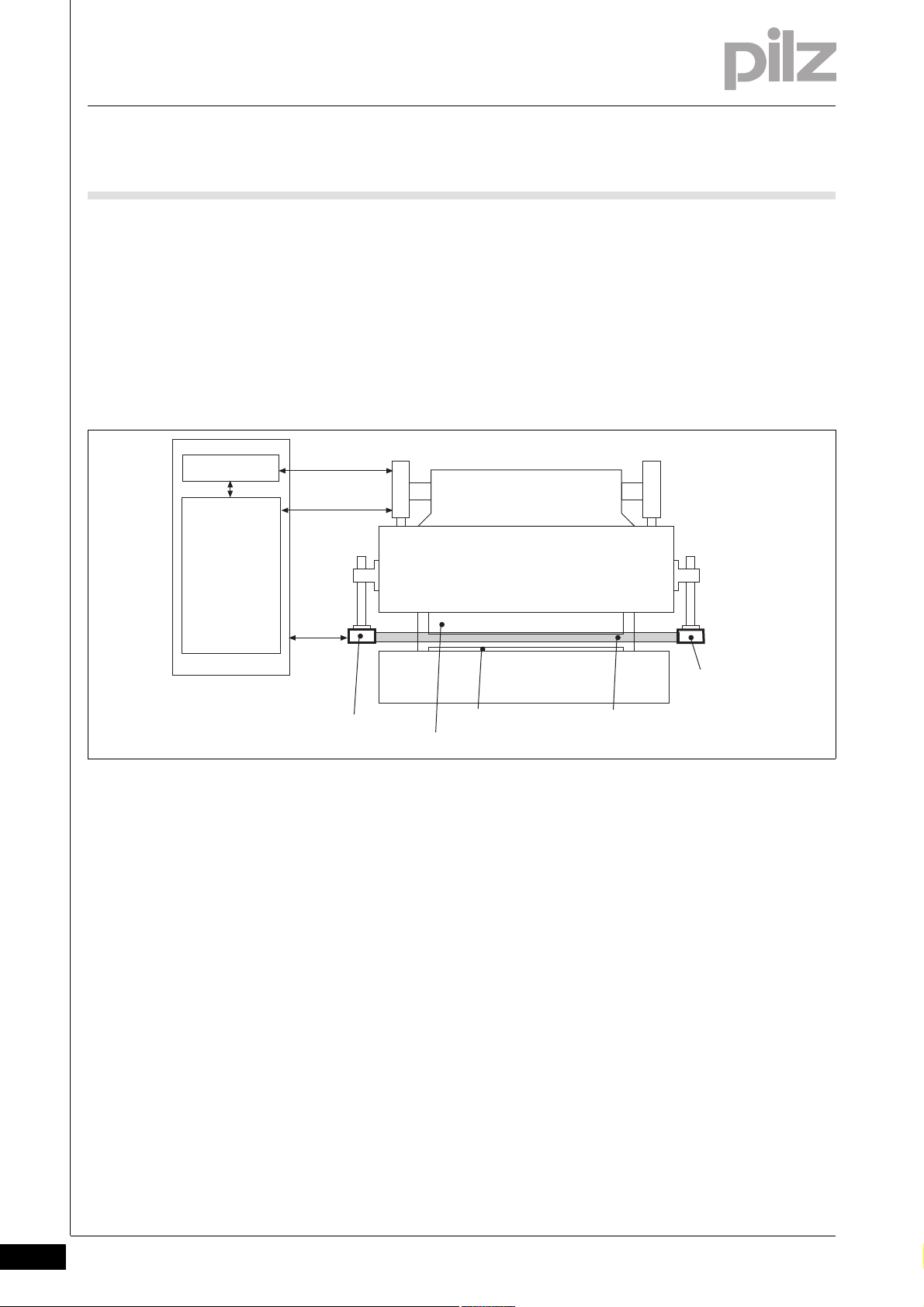
Upper die
Safety control
system
CNC
Receiver
Lower tool
Detection zone
Upper tool
Transmitter
Uebersicht_Gesamtsystem
Tool detection
Automatic detection of tool contour during tool change
Assignment of tool to a tool class
The whole system consists of:
Press brake
Numerical controller (CNC)
Programmable safety system
PSENvip (transmitter and receiver)
Fig. 2-1: Whole system
2-2
Pilz GmbH & Co. KG, Felix-Wankel-Straße 2, 73760 Ostfildern, Germany
Telephone: +49 711 3409-0, Telefax: +49 711 3409-133, E-Mail: pilz.gmbh@pilz.de
Page 15

2 Overview
2.1 Scope of supply
2.1Scope of supply2100Scope of supply2-Grundlagen
PSENvip RL D P Set: complete set
Order reference Description
PSENvip RL D P PSENvip receiver, left, with display
and dynamic muting
PSENvip T PSENvip transmitter
PSENvip AT mag Adjustment templates with magnets
PSENvip AP Set of adjustment plates for transmit-
ter/receiver
PSENvip TP Test piece in accordance with
EN 12622, Annex H
DVD with operating manuals
Pilz GmbH & Co. KG, Felix-Wankel-Straße 2, 73760 Ostfildern, Germany
Telephone: +49 711 3409-0, Telefax: +49 711 3409-133, E-Mail: pilz.gmbh@pilz.de
2-3
Page 16

2 Overview
2-4
Pilz GmbH & Co. KG, Felix-Wankel-Straße 2, 73760 Ostfildern, Germany
Telephone: +49 711 3409-0, Telefax: +49 711 3409-133, E-Mail: pilz.gmbh@pilz.de
Page 17

3 Safety
3.1 Intended use
33000SafetySafety3-3.1Intended use3100Intended use3-Sicherheit_Bestimm_Allg
Sicherheit_Bestimm_Allg_dyn_Muting
The PSENvip is exclusively designed for stationary use on press brakes.
As electrosensitive protective equipment (ESPE), the PSENvip meets
the requirements of a type 4 ESPE in accordance with EN 61496-1.
The PSENvip safeguards the danger zone below the moving upper tool.
Danger zones outside of the protected field are not protected. Hazards
in the area of the lower tool and above the protected field must be protected by the press manufacturer with appropriate measures. Please refer to the guidelines given in the "Tool shapes" section in this chapter.
The protected field monitors the danger zone between upper tool and
plate up to a remaining gap of 6 mm (dynamic muting)
Sicherheit_Bestimm_Allg_NLW
Sicherheit_Bestimm_Allg_Zusaetze
The upward movement of the press is assumed as a safe movement.
Use of the PSENvip RL D P Set is only permitted with the automation
system PSS 4000 from Pilz. In the PSS 4000 user program, safety functions must be implemented to safeguard the dynamic muting of
PSENvip:
Monitoring of the pinch point
Monitoring of the press braking ramp
Definition of a safe position and safe speed for the upper tool
Activation of the entire protected field via System-Init = 1, when the
press stops during dynamic muting and then the upward movement
is initiated.
For this safety function Pilz provides a certified evaluation program for
the PSS 4000.
The press brake must observe a max. overrun of 14 mm.
The following is deemed improper use:
Any structural, technical or electrical modification to the PSENvip
Use of the PSENvip outside the zones described in this manual
Use of the PSENvip contrary to the documented technical details (see
chapter entitled "Technical Details")
Intended use includes making the wiring EMC-compliant. Please refer to
the guidelines stated in this manual, in the section entitled "Wiring".
The protective function of the PSENvip must not be adversely affected
by sources of interference, e.g. wireless remote controls for cranes,
welding sparks, strobe lighting effects.
Pilz GmbH & Co. KG, Felix-Wankel-Straße 2, 73760 Ostfildern, Germany
Telephone: +49 711 3409-0, Telefax: +49 711 3409-133, E-Mail: pilz.gmbh@pilz.de
3-1
Page 18
3 Safety
4
4
4
3.1 Intended use
3.1.1 Approvals
Approvals3-Sicherheit_Zulassungen
3.1.2 Safety during operation
Safety during operation3-Sicherheit_Betrieb_Allg
Intended use also includes awareness of the hazards that arise during
operation, against which the PSENvip does not provide protection.
3.1.2.1 Hazards arising from the installation of the PSENvip
Hazards arising from the installation of the PSENvip3-Sicherheit_Betrieb_Montage
When installing the PSENvip, please note the following:
The PSENvip must be installed so that there are no crushing or shear-
ing hazards between the moving transmitter/receiver and the fixed
machine parts or any other parts around the machine.
If hazard areas cannot be avoided, other safeguards must be put in
place.
3.1.2.2 Hazards arising from a reduced protected field
Hazards arising from a reduced protected field3-Sicherheit_Betrieb_Schutzfeld_reduziert
The full protected field is only active in standard protected field mode.
In box bending or box bending with back gauge protected field mode,
the protected field is reduced. This means there can only be limited protection against trapping and crushing. The protected field is around the
tolerance zone behind the bending line. Any parts of the body within the
danger zone will only be detected behind the bending line. There is a risk
of injury from trapping or crushing.
3-2
Pilz GmbH & Co. KG, Felix-Wankel-Straße 2, 73760 Ostfildern, Germany
Telephone: +49 711 3409-0, Telefax: +49 711 3409-133, E-Mail: pilz.gmbh@pilz.de
Page 19

3 Safety
3.1 Intended use
3.1.2.3 Hazards arising from incorrect handling of the workpiece
Hazards arising from incorrect handling of the workpiece3-Sicherheit_Betrieb_Handhabung_Werkstueck_falsch
The PSENvip does not protect against hazards arising from incorrect
handling of the workpiece.
When bending metal sheets on press brakes there is a risk of hand injuries
From the tool's closing movement
From the swivel movement of the parts of the metal sheet that pro-
trude from the tool and
From the dropping of the metal sheet when the tool is opened.
So please note the following:
You can avoid crushing and trapping of fingers or hands if the work-
piece is handled correctly.
Wear protective gloves to prevent cuts from edges, corners and ridg-
es.
3.1.2.4 Correct handling of the workpiece
Correct handling of the workpiece3-Sicherheit_Warnung_Quetschen_1
WARNING!
Crushing and trapping of fingers or hands!
With box bending and/or back gauge bending mode, the protected field is partly blanked.
Around the bending line there is an increased risk of crushing
and trapping of fingers or hands.
Pilz GmbH & Co. KG, Felix-Wankel-Straße 2, 73760 Ostfildern, Germany
Telephone: +49 711 3409-0, Telefax: +49 711 3409-133, E-Mail: pilz.gmbh@pilz.de
3-3
Page 20
3 Safety
3.1 Intended use
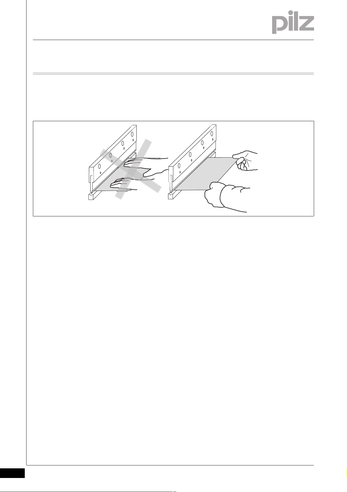
Sicherheit_Betrieb_Handhabung_Werkstueck_richtig
Correct handling with flat workpieces
Grip the metal sheet by the front corners. Thumbs should be on top
of the sheet, palms should hold the sheet from below.
Fig. 3-1: Handling flat workpieces
3-4
Pilz GmbH & Co. KG, Felix-Wankel-Straße 2, 73760 Ostfildern, Germany
Telephone: +49 711 3409-0, Telefax: +49 711 3409-133, E-Mail: pilz.gmbh@pilz.de
Page 21
3 Safety
3.1 Intended use
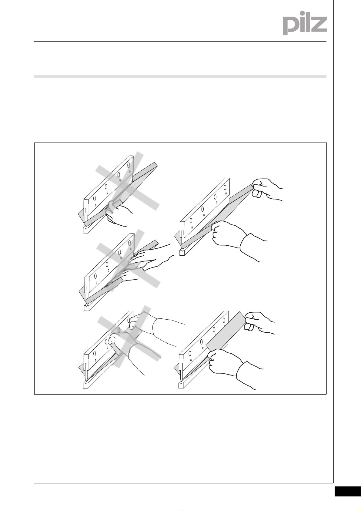
Correct handling with box bending
Hold the sheet on the right and left between the thumb and index fin-
ger.
As you hold the sheet, do not reach with your hands into the box. Dur-
ing the bending operation, fingers or hands can become crushed or
trapped between the workpiece and upper tool.
Fig. 3-2: Handling box bending
Pilz GmbH & Co. KG, Felix-Wankel-Straße 2, 73760 Ostfildern, Germany
Telephone: +49 711 3409-0, Telefax: +49 711 3409-133, E-Mail: pilz.gmbh@pilz.de
3-5
Page 22

3 Safety
3.1 Intended use
3.1.3 Categories / SIL
Categories / SIL3-Sicherheit_Kategorien_P_Variante
3.1.4 Tool shapes
Tool shapes3-Sicherheit_Werkzeugformen
The PSENvip may only be used with an automation system PSS 4000
from Pilz with SIL 3 of EN 61508 and PL e of EN ISO 13849-1.
Please note: To achieve the corresponding category or SIL, the whole
system including all safety-related components (parts, devices, user
program etc.) must be included in the assessment. For this reason, Pilz
cannot accept liability for the correct classification into a category or
SIL.
All tool shapes are permitted in principle. They are divided into tool
classes by the PSENvip. Classification is based on EN 12622, according
to which the protected field must safeguard areas lying 15 mm in front
of the bending line.
INFORMATION
Please refer to the information on tool classes
In the section entitled "Adjustment during tool change", under
"Commissioning".
In the section entitled "Requirements of the user program", un-
der "System Connections".
Please note the following when using tools:
Tool class 1
These tools can be safeguarded in compliance with the standards:
The front and rear bending lines are detected by the protected field
on the PSENvip. The front segments of the protected field are more
than 15 mm away from the front bending line.
Upper tools with a width of max. 32 mm or radius of max. 25 mm.
Press brakes can travel up to the regular switchover point at high
closing speed.
3-6
Tool class 2
These tools cannot be safeguarded in compliance with the standards:
The front and rear bending lines are detected by the protected field
on the PSENvip. The front segments of the protected field are less
than 15 mm away from the front bending line.
Upper tools with a width of max. 43 mm or radius of max. 50 mm.
Pilz GmbH & Co. KG, Felix-Wankel-Straße 2, 73760 Ostfildern, Germany
Telephone: +49 711 3409-0, Telefax: +49 711 3409-133, E-Mail: pilz.gmbh@pilz.de
Page 23

3 Safety
3.1 Intended use
The following safety guideline applies for press brakes with tools in
this tool class.
WARNING!
Crushing and trapping of fingers or hands!
There may be additional hazard areas in zones that are not monitored by the PSENvip.
In these zones there is an increased risk of crushing and trapping of fingers or hands.
Secure these zones with appropriate additional measures!
– Carry out a hazard analysis!
– Raise the regular switchover point, which initiates braking at
low speed! The switchover point must be monitored by the
safety system.
Tool class 3
These tools cannot be safeguarded in compliance with the standards:
The front and rear bending lines are not detected by the protected
field on the PSENvip.
The following safety guideline applies for press brakes with tools in
this tool class.
WARNING!
Crushing and trapping of fingers or hands!
There may be additional hazard areas in zones that are not monitored by the PSENvip.
In these zones there is an increased risk of crushing and trapping of fingers or hands.
Secure these zones with appropriate additional measures!
– Carry out a hazard analysis!
– Raise the switchover point, which initiates braking at low
speed. It must be placed even higher than the position used
for tools of tool class 2. The switchover point must be monitored by the safety system.
– Each press stroke must be acknowledged by the operator
prior to initiation.
Sicherheit_Werkzeugformen_Beispiele
Pilz GmbH & Co. KG, Felix-Wankel-Straße 2, 73760 Ostfildern, Germany
Telephone: +49 711 3409-0, Telefax: +49 711 3409-133, E-Mail: pilz.gmbh@pilz.de
3-7
Page 24
3 Safety
3.1 Intended use
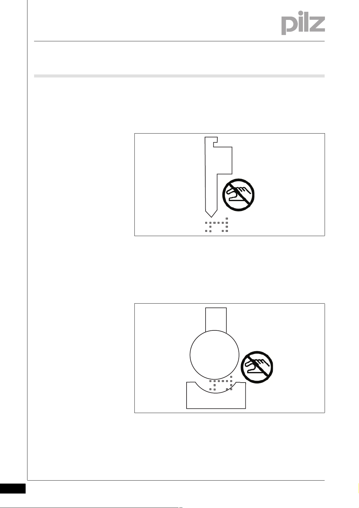
Please also note the following guidelines in danger zones in areas that
cannot be detected and monitored by the safeguard.
Example: Upper tool with a danger zone outside the zone monitored by
the PSENvip
Fig. 3-3: Danger zone in unmonitored zone
Example: In unmonitored zones, the use of tools which are not fully detected by the protected field on the PSENvip (e.g. tools with a radius
greater than 25 mm) will lead to the risk of fingers or hands being
crushed or trapped!
3-8
Fig. 3-4: Crush points when the tool is wider than the protected field
Pilz GmbH & Co. KG, Felix-Wankel-Straße 2, 73760 Ostfildern, Germany
Telephone: +49 711 3409-0, Telefax: +49 711 3409-133, E-Mail: pilz.gmbh@pilz.de
Page 25

3 Safety
3.2 Standards
3.2Standards3200St andards3-Sicherheit_Normen
To use the PSENvip correctly you will need to have a good knowledge
of the relevant standards and directives. The following gives an overview
of the most important standards:
EN 61496-1:2004: Safety of machinery - Electrosensitive protective
equipment, Part 1
CLC/TS 61496-2:2006: Safety of machinery - Electrosensitive protec-
tive equipment, Part 2
EN 12622:2009: Machine tools - Hydraulic press brakes
EN ISO 13849-1:2008: Safety of machinery – Safety-related parts of
control systems - Part 1: General principles for design
EN ISO 13849-2:2008: Safety of machinery – Safety-related parts of
control systems - Part 2: Validation
EN 61508:2001: Functional safety of safety-related electrical/elec-
tronic/programmable electronic systems
Please note this is not an exhaustive list of safety standards and directives.
Pilz GmbH & Co. KG, Felix-Wankel-Straße 2, 73760 Ostfildern, Germany
Telephone: +49 711 3409-0, Telefax: +49 711 3409-133, E-Mail: pilz.gmbh@pilz.de
3-9
Page 26

3 Safety
3.3 Safety guidelines
3.3Safety guidelines3300Safety guidelines3-Sicherheit_Sicherheitsrichtlinien_Allgemein
Failure to keep to these guidelines will render all warranty and liability
claims invalid:
All health and safety / accident prevention regulations for the particu-
lar area of application must be observed.
Before using the unit it is necessary to perform a safety assessment
in accordance with the Machinery Directive 2006/42/EC.
Please note that manufacturers and company operators who use the
PSENvip are themselves responsible for agreeing the regulations with
the relevant authorities and complying with them.
3.3.1 Use of qualified personnel
Use of qualified personnel3-Sich Qualif. Personal
Sicherheit_Qualifikation_BWS
The products may only be assembled, installed, programmed, commissioned, operated, maintained and decommissioned by competent persons.
A competent person is someone who, because of their training, experience and current professional activity, has the specialist knowledge required to test, assess and operate the work equipment, devices,
systems, plant and machinery in accordance with the general standards
and guidelines for safety technology.
It is the company's responsibility only to employ personnel who:
Are familiar with the basic regulations concerning health and safety /
accident prevention
Have read and understood the safety guidelines given in this descrip-
tion
Have a good knowledge of the generic and specialist standards ap-
plicable to the specific application.
Approved personnel must be familiar with how to use and test ESPE and
be authorised by the ESPE operator to do this.
3-10
3.3.2 EMCD
EMCD3-Sicherheit_EMVG
The PSENvip is designed for use in an industrial environment. It is not
suitable for use in a domestic environment, as this can lead to interference.
Pilz GmbH & Co. KG, Felix-Wankel-Straße 2, 73760 Ostfildern, Germany
Telephone: +49 711 3409-0, Telefax: +49 711 3409-133, E-Mail: pilz.gmbh@pilz.de
Page 27

3 Safety
3.3 Safety guidelines
3.3.3 Warranty and liability
Warranty and liability3-Sich Gewhrleistung
All claims to warranty and liability will be rendered invalid if:
The product was used contrary to the purpose for which it is intended
Damage can be attributed to not having followed the guidelines in the
manual
Operating personnel are not suitably qualified
Any type of modification has been made (e.g. exchanging compo-
nents on the PCB boards, soldering work etc.).
3.3.4 Safety during commissioning, installation and operation
Safety during commissioning, installation and operation3-Sicherheit_Inbetriebnahme_Montage_Betrieb
Please read the guidelines stated in the chapters entitled "Commissioning", "Installation" and "Operation".
3.3.5 Disposal
Disposal3-Si ch Entsorgung
In safety-related applications, please comply with the mission time t
M
in the safety-related characteristic data.
When decommissioning, please comply with local regulations regard-
ing the disposal of electronic devices (e.g. Electrical and Electronic
Equipment Act).
Pilz GmbH & Co. KG, Felix-Wankel-Straße 2, 73760 Ostfildern, Germany
Telephone: +49 711 3409-0, Telefax: +49 711 3409-133, E-Mail: pilz.gmbh@pilz.de
3-11
Page 28

3 Safety
3-12
Pilz GmbH & Co. KG, Felix-Wankel-Straße 2, 73760 Ostfildern, Germany
Telephone: +49 711 3409-0, Telefax: +49 711 3409-133, E-Mail: pilz.gmbh@pilz.de
Page 29
4 Function description
3
12
4 56
4.1 Overview
44000Function descriptionFunction description4-4.1Overview4100Overview4-Funktion_Ueberblick_P_Variante
The PSENvip is a camera-based protection system for press brakes. It
consists of a transmitter and receiver, which are fixed to the moving part
of the press brake, the upper die. The detection zone between the transmitter and receiver monitors the immediate danger zone below the moving upper tool.
The detection zone moves with the upper die, providing mobile safeguarding of the danger zone. If an object encroaches into the detection
zone, both output signal switching devices (OSSD1, OSSD2) on the
PSENvip will switch to the OFF-state. The safety system will use these
signals to initiate stopping of the press stroke.
Fig. 4-1: Press brake with PSENvip
1: Upper tool
2: Upper die
3: Receiver
4: Detection zone
5: Lower tool
Funktion_Gesamtsystem_P_Variante
6: Transmitter
The PSENvip is part of an overall system comprising
PSENvip transmitter and receiver
Programmable safety system PSS 4000
CNC controller
Signals from incremental encoders for defining the position and
speed
External operator elements or signals (foot switch, reset button for re-
duced protected field or setup mode, E-STOP pushbutton)
Pilz GmbH & Co. KG, Felix-Wankel-Straße 2, 73760 Ostfildern, Germany
Telephone: +49 711 3409-0, Telefax: +49 711 3409-133, E-Mail: pilz.gmbh@pilz.de
4-1
Page 30
4 Function description
OSSD 1
OSSD 2
Mute 1
TRM_ON
TRM_SYNC
TRM_ON
TRM_SYNC
Programmable safety
system
PSS 4000
Incremental encoder
Mute 2
Pinch point
Up/
Down
Power Off
System-Init
Protected field mode
Acknowledgement of reduced
protected field
Inputs
Outputs
PSENvip receiver
PSENvip transmitter
CNC controller
Protected field mode
Setup
Foot switch
E-STOP
E-STOP contactor
User program
Safety valve
Prefill valve
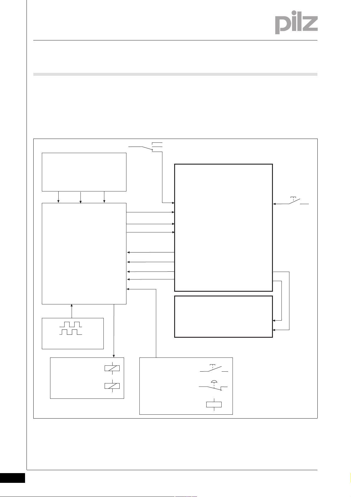
4.1 Overview
Other safety devices (safety valves, prefill valve, contactor for E-
STOP)
The following overview shows the fundamentals of the whole system.
The signals from the PSENvip transmitter and receiver are explained in
the sections below.
Funktion_Geraete_Schutzfeldmodus
4-2
Pilz GmbH & Co. KG, Felix-Wankel-Straße 2, 73760 Ostfildern, Germany
Telephone: +49 711 3409-0, Telefax: +49 711 3409-133, E-Mail: pilz.gmbh@pilz.de
Fig. 4-2: Overview of overall system
Page 31

4 Function description
4.1 Overview
INFORMATION
Some inputs and outputs on the receiver are also used for communication with the safety system (see section entitled "Communication with the safety system"). If communication is not
required, protected field mode can also be controlled directly via
the CNC controller.
Funktion_PSS_4000
The motion sequence of the press is monitored by the automation system PSS 4000. In the PSS 4000 user program safety functions must be
implemented to safeguard the dynamic muting of PSENvip. (see chapter
Funktion_Optik
10 "System Connections").
Funktion_Schutzraum
The receiver evaluates the parallel beams generated by the transmitter.
The beam is enclosed by the illuminated target area. The lens on the receiver only detects light that runs parallel to the optical axis. This guarantees stability against diffused light.
WARNING!
The light generated by the transmitter is not hazardous to the
human eye.
However, do not use additional optical aids, e.g. lenses, to look
at the light from the transmitter. This could damage the eye.
The receiver monitors and evaluates the detection zone between the
transmitter and receiver. The protected field is the cross section of the
detection zone. It consists of several segments.
Pilz GmbH & Co. KG, Felix-Wankel-Straße 2, 73760 Ostfildern, Germany
Telephone: +49 711 3409-0, Telefax: +49 711 3409-133, E-Mail: pilz.gmbh@pilz.de
4-3
Page 32

4 Function description
1
2
3
4
4.1 Overview
Funktion_Schutzfeld_allgemein
Fig. 4-3: Definitions
Key:
1: Light beam bundle
2: Illuminated target area
3: Protected field
4: Detection zone
The shape and size of the protected field depend on the bending function and the machine-dependent overrun. A reduced protected field is
possible for box bending and/or back gauge mode (for the size of the
protected field please see "Protected field" section and the chapter entitled "Technical Details").
If an object encroaches into the detection zone, both output signal
switching devices (OSSD1 and OSSD2) on the PSENvip will switch to
the OFF-state. The safety system will use these signals to initiate stopping of the press stroke.
4-4
Pilz GmbH & Co. KG, Felix-Wankel-Straße 2, 73760 Ostfildern, Germany
Telephone: +49 711 3409-0, Telefax: +49 711 3409-133, E-Mail: pilz.gmbh@pilz.de
Page 33

4 Function description
Bending line
Upper tool
Illuminated target area
Rear segments
Workpiece
Lower tool
Adjustment line
Front segments
Central segments
44
max. 20
min. 8
6
1
Overrun distance 2 m
Overrun distance 14 mm
4.2 Protected field
4.2Protected field4200Protected field4-Funktion_Schutzfeld
The protected field consists of several segments. The front and rear segments (viewed from the operator's side) can be deactivated. This provides flexibility to adapt to the bending function:
Standard
Full protected field: all segments active
Box bending
Reduced protected field: front segments deactivated
Bending with back gauge
Reduced protected field: rear segments deactivated
Box bending with back gauge
Reduced protected field: front and rear segments deactivated
Funktion_Schutzfeld_Groesse
Funktion_Schutzfeld_Info_Kastenbiegen
Pilz GmbH & Co. KG, Felix-Wankel-Straße 2, 73760 Ostfildern, Germany
Telephone: +49 711 3409-0, Telefax: +49 711 3409-133, E-Mail: pilz.gmbh@pilz.de
Fig. 4-4: Protected field definitions
The height of the protected field depends on the overrun. For the setting
range of the overrun please see following figure and Chapter 11, "Technical Details".
Fig. 4-5: Size of the detection zone
4-5
Page 34

4 Function description
max. 20
0,4
4.2 Protected field
INFORMATION
Please note that the central segments are 1 mm behind the
bending line. With box bending you must ensure that the side
panels of the box do not encroach into this area.
Funktion_Schutzfeld_Hinweise
The two following sections explain the basic mode of action of the protected field during a press stroke (interrupted and uninterrupted).
INFORMATION
The cycle of a press stroke with the corresponding inputs and
outputs is explained in this chapter, in the section entitled "System cycle".
4.2.1 Dynamic muting
Funktion_vorauseilendes_Messfeld_Muting_Allgemein
Dynamic muting4-
Funktion_vorauseilendes_Messfeld_Groesse
Funktion_vorauseilendes_Messfeld_Muting_Zustaende
An advance measuring field is located below the protected field. If is interrupted, the dynamic muting is started. The dynamic muting ensures
that the danger zone between upper tool and plate is monitored up to a
remaining gap of 6 mm during the downward movement.
The distance of the advance measuring field to the lower edge of the
protected field is constant. The distance to the top edge of the protected
field varies according to the length of the overrun.
Fig. 4-6: Distance of advance measuring field from protected field
4-6
Procedure:
1. The press is on downward movement. The protected field moves
down with the upper tool.
2. The advance measuring field touches the workpiece. The outputs
Mute1 and Mute2 at the receiver are set = 0.
Pilz GmbH & Co. KG, Felix-Wankel-Straße 2, 73760 Ostfildern, Germany
Telephone: +49 711 3409-0, Telefax: +49 711 3409-133, E-Mail: pilz.gmbh@pilz.de
Page 35

4 Function description
6 mm
4.2 Protected field
3. The advance measuring field is used to hold the protected field stationary at the pinch point on the workpiece. The segment division is
optimised for the dynamic muting process.
4. The respective upper segments are deactivated before the upper tool
enters the protected field.
NOTICE
The control system may only override the safety function from a
remaining gap of 6 mm.
Signal statuses of the outputs Mute1/Mute2 and OSSD1/OSSD2
full protected field active
OSSD1/ OSSD2 = 1
Mute1/Mute2 = 1
full protected field active
advance measuring field touches
plate
OSSD1/ OSSD2 = 1
Mute1/Mute2 = 1 -> 0
Remaining gap = 6mm
OSSD1/ OSSD2 = 1 -> 0
Mute1/Mute2 = 0
Pilz GmbH & Co. KG, Felix-Wankel-Straße 2, 73760 Ostfildern, Germany
Telephone: +49 711 3409-0, Telefax: +49 711 3409-133, E-Mail: pilz.gmbh@pilz.de
4-7
Page 36

4 Function description
4.2 Protected field
The signal statuses of the outputs Mute1/Mute2 and OSSD1/OSSD2
when interrupting the protected field by side intervention or interruption
of the advance measuring field before reaching the plate are described
in section entitled "Standard interrupted press stroke".
4.2.2 Standard interrupted press stroke
Standard interrupted press stroke4-Funktion_Pressenhub_mit_Unterbrechung_dyn_mute
It is necessary to distinguish between
Interruption of the advance measuring field
and
Side intervention with full protected field and reduced protected field
during the dynamic muting
Interruption of the advance measuring field
1
Downward movement
Object interrupts advance
measuring field, starts dynamic muting
OSSD1/OSSD2 = 1
Mute1/Mute2 = 1 -> 0
Safety system initiated the
stopping of the press,
measuring field was not interrupted in the expected
position (pinch point)
2
Upper tool continues moving for the overrun distance.
Protected field interrupted
Object is removed Protected field cleared. Press
stroke can be resumed.
4-8
Pilz GmbH & Co. KG, Felix-Wankel-Straße 2, 73760 Ostfildern, Germany
Telephone: +49 711 3409-0, Telefax: +49 711 3409-133, E-Mail: pilz.gmbh@pilz.de
Page 37

4 Function description
4.2 Protected field
Side intervention with full protected field or reduced protected field
during the dynamic muting
1
Object interrupts the protected field to the side:
OSSD1/OSSD2= 1 -> 0
Mute1/Mute2 = 1
Safety system initiates the
stopping of the press stroke
2
Upper tool continues moving for the overrun distance.
Protected field interrupted
Object is removed Protected field cleared. Press
stroke can be resumed.
Pilz GmbH & Co. KG, Felix-Wankel-Straße 2, 73760 Ostfildern, Germany
Telephone: +49 711 3409-0, Telefax: +49 711 3409-133, E-Mail: pilz.gmbh@pilz.de
4-9
Page 38

4 Function description
4.3 Overrun
4.3Overrun4300Overrun4-Funktion_Nachlaufweg_Allgemein
The max. overrun is a press brake variable that will depend on the machine type. Once the closing movement has stopped, the max. overrun
must not be exceeded.
The overrun is entered during configuration via the keypad on the
PSENvip receiver.
INFORMATION
Please refer to chapter 11, "Technical Details", for more information about the input area of the overrun.
Details on how to enter the overrun are described in Chapter 7,
“Commissioning”, section entitled “Enter overrun”.
Funktion_Nachlaufweg_P_Variante
Funktion_Nachlaufweg_Warnung_3
Normally, the factory-assigned overrun is sufficient and does not have
to be configured.
WARNING!
If you require a different overrun path than the factory-set path,
then use the value indicated by the manufacturer on the nameplate of the press brake, or a higher value.
If you enter a lower value for the overrun, the protected field will
also be reduced to an unpermitted level.
Failure to comply could result in a hazardous situation, which
could lead to serious injury and death.
4-10
Pilz GmbH & Co. KG, Felix-Wankel-Straße 2, 73760 Ostfildern, Germany
Telephone: +49 711 3409-0, Telefax: +49 711 3409-133, E-Mail: pilz.gmbh@pilz.de
Page 39

4 Function description
1
2
3
4
4.4 Description of the units
4.4Description of the units4400Descriptio n of the units4-
4.4.1 Overview
Overview4-Funktion_Geraete_Sender_Empfaenger
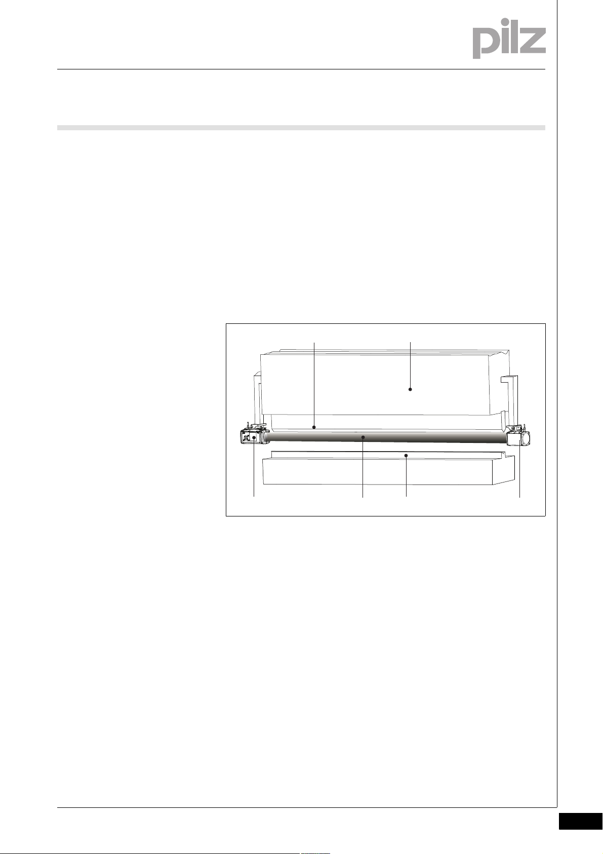
The transmitter and receiver form one unit. The receiver contains all the
inputs and outputs required for communication with the CNC controller,
programmable safety system, transmitter and press brake. The trans-
Funktion_Geraete_Sender_Empfaenger_RL_D
mitter merely contains the inputs for controlling the light source.
4.4.2 Transmitter
Transmitter4-Funktion_Geraete_Sender_Stecker
4.4.2.1 Inputs
Inputs4-Funktion_Geraete_Sender_Eingang_TRM_ON_TRM_SYNC
Fig. 4-7: Transmitter and receiver
1: Display
2: Receiver
3: LED: OSSD status
4: Transmitter
The top of the transmitter has a 4-pin M12 connector.
The receiver uses these standard inputs to control the transmitter's light
source. The user cannot influence these internal signals.
TRM_ON
The receiver uses this signal to switch the transmitter's light source
on and off.
TRM_SYNC
The receiver uses this signal to control the intensity of the transmitter's light source.
Pilz GmbH & Co. KG, Felix-Wankel-Straße 2, 73760 Ostfildern, Germany
Telephone: +49 711 3409-0, Telefax: +49 711 3409-133, E-Mail: pilz.gmbh@pilz.de
4-11
Page 40

4 Function description
4.4 Description of the units
4.4.3 Receiver
Receiver4-Funktion_Geraete_Empfaenger_Stecker
The top of the receiver has two 8-pin M12 connectors.
4.4.3.1 Inputs
Inputs4-Funktion_Geraete_Empfaenger_Eingaenge_1_P
Funktion_Geraete_Empfaenger_Eingaenge_2
System-Init
Input whose signal comes from the safety system PSS 4000.
System-Init = 1: Press at top dead centre or in an upward movement
System-Init = 0: Downward movement
The PSENvip can perform internal availability tests and completely
activate the protected field when System-Init = 1. The outputs OSSD
and mute are in the OFF state (OSSD = 0, Mute = 0).
Funktion_Geraete_Empfaenger_Eingaenge_3
INFORMATION
Please note that the PSENvip independently carries out an internal safety test every 2 minutes, if such a test is not requested
within this time by an external control system through SystemInit = 1. The PSENvip switches the OSSDs off during the safety
tests. For this reason you should ensure that the safety tests are
requested by an external control system before these 2 minutes
have elapsed. The best time to do this is when the OSSDs are
already switched off due to the position within the press stroke,
e.g. at top dead centre.
Power Off
Input signalling that the press brake is in setup mode.
Power Off = 1: Setup mode activated
All safety functions are deactivated in setup mode.
– The display is switched on.
–The OSSD LED on the receiver lights up red.
– The light source is switched off.
4-12
INFORMATION
The Power Off input has another function during the system status TEST. It is used for communication with the safety system.
See "Communication with a safety system" in this section.
Pilz GmbH & Co. KG, Felix-Wankel-Straße 2, 73760 Ostfildern, Germany
Telephone: +49 711 3409-0, Telefax: +49 711 3409-133, E-Mail: pilz.gmbh@pilz.de
Page 41

4 Function description
4.4 Description of the units
Acknowledgement
Input to acknowledge that a press stroke is to be performed with a
reduced protected field (front and/or rear segments blanked). The
protected field mode selected is shown on the receiver's display.
Acknowledgement = 0/1 pulse edge via pushbutton: Run selected
protected field mode
Protected field mode 1/protected field mode 2
Two safe inputs for setting the protected field mode. The CNC or
safety system provides the signal. It is only absolutely necessary to
connect the inputs to a safety system if communication is needed for
tool detection.
Protected
field mode
12
0 0 Standard
10Box bending
0 1 Bending with back gauge
1 1 Box bending with back gauge
INFORMATION
The inputs for protected field mode have another function during
the system status TEST. They are used for communication with
the safety system. See "Communication with a safety system" in
this section.
Bending function
Pilz GmbH & Co. KG, Felix-Wankel-Straße 2, 73760 Ostfildern, Germany
Telephone: +49 711 3409-0, Telefax: +49 711 3409-133, E-Mail: pilz.gmbh@pilz.de
4-13
Page 42

4 Function description
4.4 Description of the units
4.4.3.2 Outputs
Outputs4-Funktion_Geraete_Empfaenger_Ausgang_OSSD
OSSD1/OSSD2 in accordance with EN 61496-1, type 4
Two safe outputs that signal the status of the protected field:
OSSD = 1: Protected field clear
Funktion_Geraete_Empfaenger_Ausgang_Mute
OSSD = 0: Protected field broken
Mute1/Mute2 in accordance with EN 61496-1, type 4
Two safe outputs that signal the dynamic muting
Mute1/Mute2 = 1: no dynamic muting
Mute1/Mute2 = 0: dynamic muting active
INFORMATION
The outputs Mute1/Mute2 have another function during the system status TEST. They are used for communication with the
safety system. See "Communication with a safety system" in
this section.
Funktion_Geraete_Empfaenger_Ausgang_Ausgangstest_Info
Funktion_Geraete_Empfaenger_Ausgang_Ausgangstest
INFORMATION
For details of the output behaviour during a press stroke please
refer also to the section entitled "System cycle", in this chapter.
INFORMATION
The outputs OSSD1/OSSD2 and Mute1/Mute2 are checked via
regular output tests.
Output test
Outputs that are switched on are checked via regular off tests.
Test pulses for outputs that are switched on: see Technical Details
Outputs that are switched on are switched off for the duration of the
test pulse.
The load must not switch off because of the test.
Outputs that are switched off are checked via regular on tests.
Test pulses for outputs that are switched off: see Technical Details
Outputs that are switched off are switched on for the duration of the
test pulse.
4-14
Pilz GmbH & Co. KG, Felix-Wankel-Straße 2, 73760 Ostfildern, Germany
Telephone: +49 711 3409-0, Telefax: +49 711 3409-133, E-Mail: pilz.gmbh@pilz.de
Page 43

4 Function description
1
t
2
t
1
t
1
t
3
t
1
t
t
2
t
1
U
0
4.4 Description of the units
The load must not switch on because of the test.
Testing for shorts
A test is regularly carried out to check for shorts between the outputs.
][Funktionsbeschreibung_BA_Zusatz Einschalttest
Fig. 4-8: Test pulses
Key:
t
: Pulse length of on test (40 μs)
1
t
: Repetition length of on test (100 μs ... 3 ms)
2
t
: Cycle time of on test (30 μs ... 5 min)
3
WARNING!
When wiring an output with capacitance it is essential to note
the pulse duration, repetition period and scan time of the powerup test, otherwise the load may switch on unintentionally.
Pilz GmbH & Co. KG, Felix-Wankel-Straße 2, 73760 Ostfildern, Germany
Telephone: +49 711 3409-0, Telefax: +49 711 3409-133, E-Mail: pilz.gmbh@pilz.de
4-15
Page 44

4 Function description
1
4.4 Description of the units
4.4.3.3 LED
LED4-Funktion_Geraete_Empfaenger_LED_OSSD
OSSD
The OSSD LED on the receiver indicates the status of the protected
field.
Green: The protected field is clear
Funktion_Geraete_Empfaenger_LED_RL_D_Abbildung
Red: Protected field is interrupted
Fig. 4-9: LED on receiver
1: OSSD LED
4-16
Pilz GmbH & Co. KG, Felix-Wankel-Straße 2, 73760 Ostfildern, Germany
Telephone: +49 711 3409-0, Telefax: +49 711 3409-133, E-Mail: pilz.gmbh@pilz.de
Page 45

4 Function description
PSENvip
12 3
46
MODE
ESC
5
MODE
ESC
4.4 Description of the units
4.4.3.4 Key display and function
Key display and function4-Funktion_Display_Allgemein
The PSENvip receiver has an integrated display. Data can be entered via
Funktion_Display_Pilz
a membrane keypad.
Funktion_Display_Legende
Funktion_Display_Tasten
Fig. 4-10: Display on the receiver
Key:
1: Navigation keys
2: <MODE> key
3: Display
4: <ESC> key
5: Tool change
6: <ENTER> key
Key functions
Key Description
Move in the direction of the arrows (scroll function) (up/
down)
Confirm entry - together with the <ENTER> key when confirming the entered overrun and making adjustments during
a tool change
Call up the operating modes: tool change and adjustment
during initial commissioning. The DIAGNOSTICS menu is
also available.
Close current window, cancel entry
Pilz GmbH & Co. KG, Felix-Wankel-Straße 2, 73760 Ostfildern, Germany
Telephone: +49 711 3409-0, Telefax: +49 711 3409-133, E-Mail: pilz.gmbh@pilz.de
4-17
Page 46

4 Function description
SYSTEM OK
OSSD ON
NORMAL OPERATION
À
Ã
Â
Á
4.4 Description of the units
Key Description
Funktion_Display_Abbildung
Display
Call up tool change operating mode directly
Confirm entry or menu option selection
Funktion_Display_Systemzustand
Fig. 4-11: Information on the display
The display is divided into 4 segments:
1: System status
2: Status of the OSSD
3: Input and display field
4: Operating status
4-18
Pilz GmbH & Co. KG, Felix-Wankel-Straße 2, 73760 Ostfildern, Germany
Telephone: +49 711 3409-0, Telefax: +49 711 3409-133, E-Mail: pilz.gmbh@pilz.de
Page 47

4 Function description
4.4 Description of the units
System status
Status Description
SYSTEM OK The PSENvip is performing the specified operating mode
TEST The PSENvip is performing calibration and internal tests.
STANDBY The PSENvip is deactivated when the press is in setup
ERROR An error has occurred (HOLD, STOP, FATAL). See
Funktion_Display_OSSD
Status of the OSSD
Status Description
OSSD ON The output signal switching devices OSSD1 and OSSD2
OSSD OFF The output signal switching devices OSSD1 and OSSD2
Funktion_Display_Betriebszustand_P_Variante
without error, see table: "Operating status"
mode.
Chapter 9, "Diagnostics and Troubleshooting"
are in the ON state.
The protected field is clear.
are in the OFF state.
The protected field is interrupted. Or the PSENvip is not in
the status: SYSTEM OK or NORMAL OPERATION
Funktion_Display_Eingabe feld
Operating state
State Description
NORMAL OPERATION
SETUP This is the operating mode in which you enter the overrun.
TOOL CHANGE This is the operating mode in which you track the adjust-
ADJUSTMENT This is the operating mode in which you set up the trans-
DIAGNOSTICS System data and error codes are displayed in this menu.
MENU On pressing the <MODE> key, you can choose between
One of the protected field modes is activated.
See Chapter 8, "Operation"
See Chapter 7, "Commissioning"
ment line to the tip of the tool during a tool change.
See Chapter 7, "Commissioning"
mitter and receiver mechanically so that they are calibrated
with each other.
See Chapter 7, "Commissioning"
Pilz technical support can use these to locate errors.
See Chapter 9, "Diagnostics and Troubleshooting"
the following
options:
- TOOL CHANGE: Adjustment during tool change
- ADJUSTMENT: Adjustment during initial commissioning
- DIAGNOSTICS: Display error codes
Pilz GmbH & Co. KG, Felix-Wankel-Straße 2, 73760 Ostfildern, Germany
Telephone: +49 711 3409-0, Telefax: +49 711 3409-133, E-Mail: pilz.gmbh@pilz.de
4-19
Page 48

4 Function description
4.4 Description of the units
The input and display field is used to
Display the active protected field mode
See chapter 8, "Operation"
Enter the overrun
See chapter 7, "Commissioning"
Menu Selection
Display the adjustment image during initial commissioning
See chapter 7, "Commissioning"
Display the adjustment image during a tool change
See chapter 7, "Commissioning"
Display of error messages and system data
See Chapter 9, "Diagnostics and Troubleshooting"
4.4.4 Communication with the safety system
Communication with the safety system4-Funktion_Kommunikation_Allg
Communication between the PSENvip and safety system is required if
you use tools that cannot be safeguarded in compliance with the standards (see section entitled "Tool shapes", under "Safety"). This is the
case with tool classes 2 and 3. User programs that do not support communication with the PSENvip can be used if you only intend to safeguard
tools of tool class 1. This is the case with older versions of the PSENvip,
for example.
Communication between the PSENvip and the PLC safety system is
conducted via digital inputs and outputs. Some inputs and outputs on
the PSENvip have another function compared to normal mode.
Communication only occurs in the system status TEST. This status is
adopted
After power-up.
After a tool change.
After a 0/1 pulse edge at the input System-Init.
Funktion_Kommunikation_P_Variante
Periodically every 2 minutes.
4-20
Pilz GmbH & Co. KG, Felix-Wankel-Straße 2, 73760 Ostfildern, Germany
Telephone: +49 711 3409-0, Telefax: +49 711 3409-133, E-Mail: pilz.gmbh@pilz.de
Page 49

4 Function description
X1, 1
PLC Ready
X2, 1
X1, 6
X2, 6
X2, 2
PSENvip
Tool class PLC -> PSENvip Bit 1
Acknowledge PSENvip -> PLC
Tool class PSENvip -> PLC Bit 1
X1, 3
X1, 4
Activate
Tool class PSENvip -> PLC Bit 2
Tool class PLC -> PSENvip Bit 2
PLC
I1
I4
I3
I2
O3
O2
O1
4.4 Description of the units
Terminal Input/output Normal mode Communication with safety sys-
X1, 1 Output No function Activate The PSENvip starts com-
X2, 1 Output No function Acknowledge PSENvip -> PLC The PSENvip confirms
X1, 6 Output Mute1 Tool class PSENvip -> PLC Bit 1 The PSENvip sends Bit 1
X2, 6 Output Mute2 Tool class PSENvip -> PLC Bit 2 The PSENvip sends Bit 2
X2, 2 Input Power Off PLC Ready The safety system is
X1, 3 Input Protected field
X1, 4 Input Protected field
Funktion_Kommunikation_Ablauf
Pilz GmbH & Co. KG, Felix-Wankel-Straße 2, 73760 Ostfildern, Germany
Telephone: +49 711 3409-0, Telefax: +49 711 3409-133, E-Mail: pilz.gmbh@pilz.de
Fig. 4-12: Digital inputs and outputs for communication
Key to inputs and outputs:
tem
Tool class PLC -> PSENvip Bit 1 The safety system re-
mode 1
Tool class PLC -> PSENvip Bit 2 The safety system re-
mode 2
Notes
munication.
the validity of the tool
class registered on the
safety system.
of the detected tool class
to the safety system.
of the detected tool class
to the safety system.
ready for communication.
flects Bit 1 of the tool
class.
flects Bit 2 of the tool
class.
4-21
Page 50

4 Function description
PLC Ready
1
0
1
0
1
0
1
0
1
0
Activate
Acknowledge PSENvip -> PLC
1
0
Tool class PSENvip -> PLC Bit 1
1
0
Tool class PSENvip -> PLC Bit 2
Tool class PLC -> PSENvip Bit 1
Tool class PLC -> PSENvip Bit 2
12345 6 7
max. 600 ms
max.
200 ms
max.
200 ms
max.
200 ms
4.4 Description of the units
Communication sequence:
4-22
Pilz GmbH & Co. KG, Felix-Wankel-Straße 2, 73760 Ostfildern, Germany
Telephone: +49 711 3409-0, Telefax: +49 711 3409-133, E-Mail: pilz.gmbh@pilz.de
1
– The PSENvip starts communication.
Activate = 0/1 pulse edge
– Tool class PLC -> PSENvip Bit 1/2: Bits can have any status
2
– The safety system is ready for communication.
PLC Ready = 0/1 pulse edge
– Tool class PLC -> PSENvip Bit 1/2 = 0 to step 5
3
The PSENvip sends the detected tool class to the safety system.
Tool class PSENvip -> PLC Bit 1 0 1 1
Tool class PSENvip -> PLC Bit 2 1 0 1
4
The PSENvip confirms the validity of the tool class registered on the
safety system in step 3.
Acknowledge PSENvip -> PLC = 0/1 pulse edge
5
– The safety system reflects the tool class transmitted by the PSEN-
vip.
– Tool class PLC -> PSENvip Bit 1/2 = 0 or 1, depending on the tool
class
Tool class
123
Page 51

4 Function description
4.4 Description of the units
Tool class PLC -> PSENvip Bit 1 0 1 1
Tool class PLC -> PSENvip Bit 2 1 0 1
6
The PSENvip ends communication.
All outputs are set = 0:
– Activate = 0
– Acknowledge PSENvip -> PLC = 0
– Tool class PSENvip -> PLC Bit 1 = 0
– Tool class PSENvip -> PLC Bit 2 = 0
7
– The safety system ends communication.
PLC Ready = 1/0 pulse edge
– Tool class PLC -> PSENvip Bit 1/2 = 0 or 1, depending on the orig-
inal status
Tool class
123
INFORMATION
The requirements of the user program in the safety system are
described under "System Connections".
Pilz GmbH & Co. KG, Felix-Wankel-Straße 2, 73760 Ostfildern, Germany
Telephone: +49 711 3409-0, Telefax: +49 711 3409-133, E-Mail: pilz.gmbh@pilz.de
4-23
Page 52

4 Function description
4.5 Protected field modes
4.5Protected field modes4500Protected field modes4-Funktion_Schutzfeldmodus
Four protected field modes are available for adapting to different bending functions:
Full protected field: Standard press stroke
Reduced protected field:
– Box bending press stroke
– Back gauge press stroke
– Box bending with back gauge press stroke
Funktion_Schutzfeldmodus_Werkzeugklasse
Use of the protected field modes depends on the tool class. Not all protected field modes can be selected with tool class 2 and 3.
Protected field mode Tool class
Standard
Full protected field
Box bending
Front segments blanked
Back gauge
Rear segments blanked
123
Yes Yes Yes
Yes Yes No
Yes No No
4.5.1 Standard protected field mode
Standard protected field mode4-Funktion_Schutzfeldmodus_Standard
The full protected field is available with standard protected field mode.
This protected field mode is applied for flat workpieces.
Fig. 4-13: Standard protected field mode
4-24
Pilz GmbH & Co. KG, Felix-Wankel-Straße 2, 73760 Ostfildern, Germany
Telephone: +49 711 3409-0, Telefax: +49 711 3409-133, E-Mail: pilz.gmbh@pilz.de
Page 53

4 Function description
1
4.5 Protected field modes
4.5.2 Box bending protected field mode
Box bending protected field mode4-Funktion_Schutzfeldmod us_Kastenbiegen
With box bending protected field mode, the front segments of the protected field are blanked. This protected field mode is used for workpieces that need to be bent several times, e.g. a box. Interruption of the front
segments is to be expected and does not cause the press stroke to
stop.
The central segments of the protected field are behind the bending line.
The box's side panels must not encroach into the central segments.
If the central or rear segments of the protected field are interrupted, the
OSSDs switch to the OFF state.
Sicherheit_Warnung_Quetschen_Kastenbiegen
Fig. 4-14: Box bending protected field mode
1: Front segments of protected field are blanked
The box bending protected field mode is only active for one press stroke
and must be acknowledged by the operator before it is initiated.
WARNING!
Crushing and trapping of fingers or hands!
With box bending protected field mode, the front segments of
the protected field are blanked.
Around the bending line there is an increased risk of crushing
and trapping of fingers or hands.
Make sure that the workpiece is handled correctly (see
Chapter 3, “Safety”).
Pilz GmbH & Co. KG, Felix-Wankel-Straße 2, 73760 Ostfildern, Germany
Telephone: +49 711 3409-0, Telefax: +49 711 3409-133, E-Mail: pilz.gmbh@pilz.de
4-25
Page 54

4 Function description
1
4.5 Protected field modes
4.5.3 Back gauge protected field mode
Back gauge protected field mode4-Funktion_Schutzfeldmodus_Anschlag
With back gauge protected field mode, the rear segments of the protected field are blanked. This protected field mode is used when the rear
back gauge extends into the vicinity of the bending line. Interruption of
the rear segments is to be expected and does not cause the press
stroke to stop.
If the front and central segments of the protected field are interrupted,
the OSSDs switch to the OFF state.
Sicherheit_Warnung_Quetschen_Anschlag
Fig. 4-15: Back gauge protected field mode
1: Rear segments of protected field are blanked
The back gauge protected field mode is only active for one press stroke
and must be acknowledged by the operator before it is initiated.
WARNING!
Crushing and trapping of fingers or hands!
With back gauge protected field mode, the rear segments of the
protected field are blanked.
Around the bending line there is an increased risk of crushing
and trapping of fingers or hands.
Make sure that the workpiece is handled correctly (see
Chapter 3, “Safety”).
4-26
Pilz GmbH & Co. KG, Felix-Wankel-Straße 2, 73760 Ostfildern, Germany
Telephone: +49 711 3409-0, Telefax: +49 711 3409-133, E-Mail: pilz.gmbh@pilz.de
Page 55

4 Function description
1
2
4.5 Protected field modes
4.5.4 Box bending with back gauge protected field mode
Box bending with back gauge protected field mode4-Funktion_Schutzfeldmodus_Kaste mbiegen_mit_Anschlag
With box bending with back gauge protected field mode, both the rear
and front segments of the protected fields are blanked. This protected
field mode is applied for workpieces that need to be bended several
times, e.g. boxes, and when the rear back gauge extends into the vicinity of the bending line. Interruption of the front and rear segments is to
be expected and does not cause the press stroke to stop.
The central segments of the protected field are behind the bending line.
The box's side panels must not encroach into the central segments.
If the central segments of the protected field are interrupted, the OSSDs
switch to the OFF state.
Fig. 4-16: Box bending with back gauge protected field mode
1: Rear segments of protected field are blanked
2: Front segments of protected field are blanked
The box bending with back gauge protected field mode is only active for
one press stroke and must be acknowledged by the operator before it is
initiated.
Sicherheit_Warnung_Quetschen_Kastenbiegen_Anschlag
WARNING!
Crushing and trapping of fingers or hands!
With box bending with back gauge protected field mode, both
the front and rear segments of the protected fields are blanked.
Around the bending line there is an increased risk of crushing
and trapping of fingers or hands.
Make sure that the workpiece is handled correctly (see
Chapter 3, “Safety”).
Pilz GmbH & Co. KG, Felix-Wankel-Straße 2, 73760 Ostfildern, Germany
Telephone: +49 711 3409-0, Telefax: +49 711 3409-133, E-Mail: pilz.gmbh@pilz.de
4-27
Page 56

4 Function description
4.6 Operating modes during commissioning
4.6Operating modes during commissioning4600Operating modes during commissioning4-Funktion_Betriebsarten_Inbetriebnahme_Allg
The PSENvip has the following options for commissioning:
Press brake setup mode
Adjustment during initial commissioning
Adjustment during tool change
4.6.1 Press brake setup mode
Press brake setup mode4-Funktion_Betriebsarten_Inbetriebnahme_Einrichten
Setup mode must be activated when work is to be carried out on the
press brake. The transmitter and receiver must be switched off. The display is switched on. By switching off the transmitter's light source the
tool setter has visual communication that there is no safety function via
the protected field. The OSSD LED on the receiver lights up red.
The input Power Off = 1 switches off the transmitter's light source.
4.6.2 Adjustment during initial commissioning
Adjustment during initial commissioning4-Funktion_Betriebsarten_Inbetriebnahme_Justage_Erstinbetriebnehme
The transmitter and receiver are aligned to each other during initial commissioning. The vertical and horizontal alignment is performed using
templates and is displayed on the receiver.
In this operating mode
The protected field is inactive.
The OSSDs are switched off.
There is no protection via the PSENvip.
INFORMATION
Details of the adjustments made during initial commissioning are
described in Chapter 7, "Commissioning", section entitled "Initial commissioning".
4-28
4.6.3 Adjustment during tool change
Adjustment during tool change4-Funktion_Betriebsarten_Inbetriebnahme_Justage_Werkzeugwechsel_1
The tool is assigned to a tool class in "Tool change" operating mode.
Once the tool data has been saved it is downloaded to the safety system.
Funktion_Betriebsarten_Inbetriebnahme_Justage_Werkzeugwechsel
The adjustment line is automatically tracked to the tip of the tool. The
tracking is shown on the display. This makes it easier to adjust to the different tool sizes.
Pilz GmbH & Co. KG, Felix-Wankel-Straße 2, 73760 Ostfildern, Germany
Telephone: +49 711 3409-0, Telefax: +49 711 3409-133, E-Mail: pilz.gmbh@pilz.de
Page 57

4 Function description
4.6 Operating modes during commissioning
INFORMATION
Generally you should not have to mechanically realign the transmitter and receiver during a tool change.
In this operating mode
The protected field is inactive.
The OSSDs are switched off.
There is no protection via the PSENvip.
INFORMATION
Details of the adjustments made during a tool change are
described in Chapter 7, "Commissioning", section entitled
"Adjustment during tool change".
Pilz GmbH & Co. KG, Felix-Wankel-Straße 2, 73760 Ostfildern, Germany
Telephone: +49 711 3409-0, Telefax: +49 711 3409-133, E-Mail: pilz.gmbh@pilz.de
4-29
Page 58

4 Function description
TDC
6 mm
BDC
v = 0
v > 0
v < 0
v = 0
6 mm
KP
Mute 1/2
4.7 System cycle
4.7System cycle4700System cycle4-Funktion_Systemablauf_Muting
This section illustrates the interdependencies of the parameters on the
press brake, PSENvip and safety system during a press stroke. The following parameters are illustrated:
Status: Describes the cycle status. The upward movement of the
press is assumed as a safe movement.
Foot switch: Start/stop press stroke
System-Init: Press brake is at top dead centre
OSSD: Output signal switching devices of the PSENvip
Protected field: Free, interrupted
Mute 1/2: signals whether dynamic muting is activated or deactivat-
ed.
Mute 1/2 are reset to "1" when the protected field is completely ac-
tivated and the advance measuring field is free.
A protected field that has already been partly deactivated can be
completely reactivated by
– side intervention
– the signal System-Init = 1
Dynamic muting:
– reset: advance measuring field touches pinch point on the work-
piece
– End: Tool centre point reaches the 6 mm point
4-30
Fig. 4-17: Definitions
Legend:
TDC top dead centre
Pilz GmbH & Co. KG, Felix-Wankel-Straße 2, 73760 Ostfildern, Germany
Telephone: +49 711 3409-0, Telefax: +49 711 3409-133, E-Mail: pilz.gmbh@pilz.de
6 mm: 6 mm point, end of dynamic muting
PP: Pinch point
BDC bottom dead centre
v = 0 mm/s closing speed at top/bottom dead centre
v > 0 mm/s downward movement
Page 59

4 Function description
v = 0
TDC
v > 0
4.7 System cycle
v > 0 mm/s upward movement
Mute 1/2: Segment switches outputs Mute 1 and Mute 2
4.7.1 System cycle for standard press stroke
System cycle for standard press stroke4-Funktion_Systemablauf_Pressenhub_Standard_Muting
Inputs on the PSENvip receiver:
Protected field mode 1 = 0
Protected field mode 2 = 0
Power Off = 0
1
Status Press is at top dead centre
Foot switch 0
System-Init 1
OSSD 0
Protected field Free
Mute 1/2 0
Dynamic muting Inactive
2
Status Downward movement
Foot switch 1
System-Init 0
OSSD 1
Protected field Free
Mute 1/2 1
Dynamic muting Inactive
Pilz GmbH & Co. KG, Felix-Wankel-Straße 2, 73760 Ostfildern, Germany
Telephone: +49 711 3409-0, Telefax: +49 711 3409-133, E-Mail: pilz.gmbh@pilz.de
4-31
Page 60

4 Function description
v > 0
KP
v > 0
KP
8 mm
v > 0
6 mm
6 mm
4.7 System cycle
3
Status Downward movement
Advance measuring field touches
plate (pinch point)
Foot switch 1
System-Init 0
OSSD 1
Protected field Free
Mute 1/2 1 -> 0
Dynamic muting Start
4
Status Downward movement
Tool centre point reaches the 8 mm
point
Foot switch 1
System-Init 0
OSSD 1
Protected field Free
Mute 1/2 0
Dynamic muting Active
5
Status Downward movement
Tool centre point reaches the 6 mm
point
Foot switch 1
System-Init 0
OSSD 1 -> 0
Muting of the OSSD in steps 5 to 8 in
the safety system
Protected field Interrupted
Mute 1/2 0
Dynamic muting End
4-32
Pilz GmbH & Co. KG, Felix-Wankel-Straße 2, 73760 Ostfildern, Germany
Telephone: +49 711 3409-0, Telefax: +49 711 3409-133, E-Mail: pilz.gmbh@pilz.de
Page 61

4 Function description
v > 0
6 mm
v = 0
BDC
v < 0
4.7 System cycle
6
Status Downward movement
Foot switch 1
System-Init 0
OSSD 0
Protected field Interrupted
Mute 1/2 0
Dynamic muting Inactive
7
Status Press is at bottom dead centre
Foot switch 1
System-Init 0
OSSD 0
Protected field Interrupted
Mute 1/2 0
Dynamic muting Inactive
8
Status Upward movement
Advance measuring field is cleared
Foot switch 1
Generally, the press travels up auto-
matically, the operator can release the
foot switch.
System-Init 1
OSSD 1 or 0
Protected field Free or interrupted
Mute 1/2 0 - > 1
Dynamic muting Inactive
Continue with step 1
Pilz GmbH & Co. KG, Felix-Wankel-Straße 2, 73760 Ostfildern, Germany
Telephone: +49 711 3409-0, Telefax: +49 711 3409-133, E-Mail: pilz.gmbh@pilz.de
4-33
Page 62

4 Function description
TDC
v = 0
v > 0
4.7 System cycle
4.7.2 System cycle for box bending press stroke
System cycle for box bending press stroke4-Funktion_Systemablauf_Pressenhub_Kastenbiegen_Muting
Inputs on the PSENvip receiver:
Protected field mode 1 = 0
Protected field mode 2 = 1
Acknowledgement of reduced protected field = Press pushbutton
and then release
1
Status Press is at top dead centre
Foot switch 0
System-Init 1
OSSD 0
Protected field Free
Mute 1/2 0
Dynamic muting Inactive
2
Status Downward movement
Foot switch 1
System-Init 0
OSSD 1
Protected field Free
Mute 1/2 1
Dynamic muting Inactive
4-34
Pilz GmbH & Co. KG, Felix-Wankel-Straße 2, 73760 Ostfildern, Germany
Telephone: +49 711 3409-0, Telefax: +49 711 3409-133, E-Mail: pilz.gmbh@pilz.de
Page 63

4 Function description
v > 0
KP
v > 0
KP
8 mm
v > 0
6 mm
6 mm
4.7 System cycle
3
Status Downward movement
Advance measuring field touches
plate (pinch point)
Foot switch 1
System-Init 0
OSSD 1
Protected field Free
Mute 1/2 1 -> 0
Dynamic muting Start
4
Status Downward movement
Tool centre point reaches the 8
mm point
Foot switch 1
System-Init 0
OSSD 1
Protected field Free
Mute 1/2 0
Dynamic muting Active
5
Status Downward movement
Tool centre point reaches the 6
mm point
Foot switch 1
System-Init 0
OSSD 1 -> 0
Muting of the OSSD in steps 5 to
8 in the safety system
Protected field Interrupted
Mute 1/2 0
Dynamic muting End
Pilz GmbH & Co. KG, Felix-Wankel-Straße 2, 73760 Ostfildern, Germany
Telephone: +49 711 3409-0, Telefax: +49 711 3409-133, E-Mail: pilz.gmbh@pilz.de
4-35
Page 64

4 Function description
v > 0
6 mm
v = 0
BDC
v < 0
4.7 System cycle
6
Status Downward movement
Foot switch 1
System-Init 0
OSSD 0
Protected field Interrupted
Mute 1/2 0
Dynamic muting Inactive
7
Status Press is at bottom dead centre
Foot switch 1
System-Init 0
OSSD 0
Protected field Interrupted
Mute 1/2 0
Dynamic muting Inactive
8
Status Upward movement
Advance measuring field is
cleared
Foot switch 1
Generally, the press travels up
automatically, the operator can
release the foot switch.
System-Init 1
OSSD 1 or 0
Protected field Free or interrupted
Mute 1/2 0 - > 1
Dynamic muting Inactive
4-36
Continue with step 1
Pilz GmbH & Co. KG, Felix-Wankel-Straße 2, 73760 Ostfildern, Germany
Telephone: +49 711 3409-0, Telefax: +49 711 3409-133, E-Mail: pilz.gmbh@pilz.de
Page 65

4 Function description
4.7 System cycle
4.7.3 System cycle for back gauge press stroke
System cycle for back gauge press stroke4-Funktion_Systemablauf_Pressenhub_mit_Anschlag
Inputs on the PSENvip receiver:
Protected field mode 1 = 1
Protected field mode 2 = 0
Acknowledgement of reduced protected field = Press pushbutton
and then release
The system cycle is the same as for box bending. Please note that with
back gauge protected field mode, the rear segments of the protected
field are blanked.
4.7.4 System cycle for box bending with back gauge press stroke
System cycle for box bending with back gauge press stroke4-Funktion_Systemablauf_Pressenhub_Kastenbiegen_mit_Anschlag
Inputs on the PSENvip receiver:
Protected field mode 1 = 1
Protected field mode 2 = 1
Acknowledgement of reduced protected field = Press pushbutton
and then release
The system cycle is the same as for box bending. Please note that with
box bending with back gauge protected field mode, both the front and
rear segments of the protected field are blanked.
Pilz GmbH & Co. KG, Felix-Wankel-Straße 2, 73760 Ostfildern, Germany
Telephone: +49 711 3409-0, Telefax: +49 711 3409-133, E-Mail: pilz.gmbh@pilz.de
4-37
Page 66

4 Function description
4-38
Pilz GmbH & Co. KG, Felix-Wankel-Straße 2, 73760 Ostfildern, Germany
Telephone: +49 711 3409-0, Telefax: +49 711 3409-133, E-Mail: pilz.gmbh@pilz.de
Page 67

5 Installation
5.1 General requirements
55000InstallationInstallation5-5.1General requirements5100General req uirements5-Montage_Allgemeine_Anforderungen
Please note for installation:
The PSENvip may only be installed by qualified personnel.
The environmental data for the PSENvip must be taken into account.
Details are available in the chapter entitled “Technical Details”.
The transmitter and receiver should be installed with the respective
front lenses aligned in parallel to each other.
The distance between the transmitter and receiver may not be greater
than the value stated in the "Technical Details".
CAUTION!
Ensure that the field of vision of the front lenses on the transmitter and receiver is not restricted. Do not attach any other optical
elements such as glass/plastic surfaces, films or lenses.
Check the fastening of the PSENvip at regular intervals.
Check that the fastening of the PSENvip is not accidentally
working its way loose as a result of vibration from the press
brake.
Pilz GmbH & Co. KG, Felix-Wankel-Straße 2, 73760 Ostfildern, Germany
Telephone: +49 711 3409-0, Telefax: +49 711 3409-133, E-Mail: pilz.gmbh@pilz.de
5-1
Page 68

5 Installation
14
+0,3
7
+0,3
15
+0,2
8,3
+0,2
1
17
+0,5
(4x) ø15
(4x) ø8.4
(32)
5
(71.5)
115
35
35
27
A-A
B
B
5.2 Install transmitter and receiver
5.2Install transmitter and receiver5200Install transmitter and receiver5-Montage_Sender_Empfaenger_Zusatz
Montage_Sender_Empfaenger
Fastening kits for the transmitter and receiver are available as acces-
sories (for order no. see Chapter 11, "Technical Details").
The fastening kit consists of an adapter plate and adjustment plate
with a slot nut. The bracket on the upper die must have a corresponding groove in which to insert the slot nut (see Fig. 5-1).
Fig. 5-1: Dimensions of adapter plate with groove, dimensions in
mm
Both the transmitter and receiver are installed in the same way. Only
the dimensions of the adjustment plates for the transmitter and receiver are different.
To install the system, proceed as follows:
Fasten the adjustment plate as shown in the diagram below. Ensure
that the flat washers, spring washers and nuts are attached in the
right order.
5-2
Pilz GmbH & Co. KG, Felix-Wankel-Straße 2, 73760 Ostfildern, Germany
Telephone: +49 711 3409-0, Telefax: +49 711 3409-133, E-Mail: pilz.gmbh@pilz.de
Page 69

5 Installation
Nut
Auxiliary adjustment plate
Adjustment plate
Flat washer
5.2 Install transmitter and receiver
Fig. 5-2: Installing the transmitter and receiver
Viewed from the operator's side, the receiver is installed on the left-hand
bracket and the transmitter on the right-hand bracket.
Slide the nut slot on the adjustment plate into the groove on the
bracket attached to the upper die.
Pilz GmbH & Co. KG, Felix-Wankel-Straße 2, 73760 Ostfildern, Germany
Telephone: +49 711 3409-0, Telefax: +49 711 3409-133, E-Mail: pilz.gmbh@pilz.de
5-3
Page 70

5 Installation
80
55
168
115.5
142.5
52
112
52
5.3 Dimensions
5.3Dimensions5300Di mensions5-
5.3.1 Transmitter
Transmitter5-Montage_Abmessungen_Sender
Fig. 5-3: Transmitter dimensions, dimensions in mm
5-4
Pilz GmbH & Co. KG, Felix-Wankel-Straße 2, 73760 Ostfildern, Germany
Telephone: +49 711 3409-0, Telefax: +49 711 3409-133, E-Mail: pilz.gmbh@pilz.de
Page 71

5 Installation
55
137
228
115.5
112
52
142.5
52
112
MODE
ESC
97.6
8
36.5
9
46
20
(162)
13
6
72
5.3 Dimensions
5.3.2 Receiver
Receiver5-Montage_Abmessungen_Empfaenger
Fig. 5-4: Receiver dimensions, dimensions in mm
5.3.3 Fastening kit for the transmitter
Fastening kit for the transmitter5-Montage_Befestigungssatz_Sender
Fig. 5-5: Dimensions of the fastening kit for the transmitter, dimen-
sions in mm
Pilz GmbH & Co. KG, Felix-Wankel-Straße 2, 73760 Ostfildern, Germany
Telephone: +49 711 3409-0, Telefax: +49 711 3409-133, E-Mail: pilz.gmbh@pilz.de
5-5
Page 72

5 Installation
156
36.5
9
76
20
13
6
8
(162)
72
5.3 Dimensions
5.3.4 Fastening kit for the receiver
Fastening kit for the receiver5-Montage_Befestigungssatz_Empfaenger
Fig. 5-6: Dimensions of the fastening kit for the receiver, dimensions
in mm
5-6
Pilz GmbH & Co. KG, Felix-Wankel-Straße 2, 73760 Ostfildern, Germany
Telephone: +49 711 3409-0, Telefax: +49 711 3409-133, E-Mail: pilz.gmbh@pilz.de
Page 73

5 Installation
1
2
3
4
5
5.3 Dimensions
5.3.5 Bracket for transmitter and receiver
Bracket for transmitter and receiver5-Montage_Haltearm
Brackets for the transmitter and receiver are available as accessories
(for order no. see Chapter 11, "Technical Details").
Details about installation can be found in the diagram below.
Fig. 5-7: Bracket for transmitter and receiver
Key:
1: left bracket
2: right bracket
3: 2 x DIN 912 M8x20 cheese head screw
4: adapter plate
5: 4 x DIN 912 M8x20 cheese head screw
Pilz GmbH & Co. KG, Felix-Wankel-Straße 2, 73760 Ostfildern, Germany
Telephone: +49 711 3409-0, Telefax: +49 711 3409-133, E-Mail: pilz.gmbh@pilz.de
5-7
Page 74

5 Installation
5-8
Pilz GmbH & Co. KG, Felix-Wankel-Straße 2, 73760 Ostfildern, Germany
Telephone: +49 711 3409-0, Telefax: +49 711 3409-133, E-Mail: pilz.gmbh@pilz.de
Page 75

6 Wiring
6.1 Notes on wiring
66000WiringWiring6-6.1Notes on wiring6100Notes on wiring6-Verdrahtung_Hinweise_Einf
Sicherheit_Achtung_unbeabsichtigter_Start
Verdrahtung_Hinweise_Netzteil
Sicherheit_Warnung_elektrischer_Schlag
Please observe the following when wiring:
CAUTION!
Unintended machine start up!
Voltage should be removed from the whole machine and
PSENvip during wiring.
Power supply
When selecting the power supply, please refer to the requirements
stated under “Technical Details”.
The power supply used to supply the PSENvip transmitter and receiv-
er must be able to bridge a power outage of 10 ms. This requirement
comes from EN 61496-1:2004: Safety of machinery – Electrosensitive
protective equipment. Supply interruptions on the PSENvip that cannot be bridged by the PSENvip will always lead to a safe condition
(OSSD1, OSSD2 in OFF condition).
Overload protection must be provided. Use a circuit breaker with
characteristic C, 4 A or 6 A, depending on the inrush current. Please
refer to the recommendations of the power supply manufacturer.
Verdrahtung_Hinweise_Kabel
WARNING!
Electric shock!
Safe electrical isolation must be ensured for the external power
supply generating the 24 V supply voltage and the voltages to
the inputs on the PSENvip. Failure to do so could result in electric shock. The power supplies must comply with EN 60950-1
and EN 61558-2-6.
Cable
The transmitter and receiver should only be connected using shielded
cables (available as accessories). The cable shield is connected to the
metal coupling on the M12 connectors.
Earth the cable shield connection within the control cabinet, e.g. on a
bus bar.
The ready-made cables from Pilz should preferably be used for con-
necting The PSENvip (see chapter 11, "Technical Details").
Protect the cable from mechanical damage. Lay the cable in such a
way that wire short circuits are excluded. If the cable is not protected
through the machine, it should be laid in armoured hose.
Pilz GmbH & Co. KG, Felix-Wankel-Straße 2, 73760 Ostfildern, Germany
Telephone: +49 711 3409-0, Telefax: +49 711 3409-133, E-Mail: pilz.gmbh@pilz.de
6-1
Page 76

6 Wiring
Protected field mode 2
Protected field mode 1
X1
3
4
24 V DC
6.1 Notes on wiring
Verdrahtung_Hinweise_EMV
Verdrahtung_Hinweise_Eingaenge_des_Empfaengers
EMC
Avoid interference (e.g. from motors, power lines) by laying cables in
a way that is EMC-compliant.
Inputs on the receiver
The inputs Protected field mode 1/Protected field mode 2 are safe-
ty-related.
– The CNC or safety system provides the signal. It is only absolutely
necessary to connect the inputs to a safety system if communication is needed for tool detection.
– When driven via relay contacts it is the user's responsibility to apply
an appropriate safety concept.
The inputs for protected field mode 1 and protected field mode 2 can
be switched directly via the 24 VDC supply. In this case, both inputs
should be linked. Only the following protected field modes are possible:
– "Standard" protected field mode (switch open, both inputs = "0")
– "Box bending with back gauge" protected field mode (switch
closed, both inputs = "1")
Verdrahtung_Hinweise_Fu nktionspruefung
6-2
Pilz GmbH & Co. KG, Felix-Wankel-Straße 2, 73760 Ostfildern, Germany
Telephone: +49 711 3409-0, Telefax: +49 711 3409-133, E-Mail: pilz.gmbh@pilz.de
Fig. 6-1: Protected field mode 1/2 directly at the 24 V DC supply
The input to acknowledge the specified protected field mode can be
switched directly via the 24 VDC supply.
NOTICE
The acknowledgement button for the protected field mode must
be positioned outside the danger zone in such a way that the
operator can see all of the danger zone.
Page 77

6 Wiring
6.1 Notes on wiring
Function test
When the wiring is complete the protective equipment will need to un-
dergo a function test.
INFORMATION
To perform the function test, follow the procedure described in
Chapter 7, "Commissioning", section entitled "Function test of
the safety device".
Pilz GmbH & Co. KG, Felix-Wankel-Straße 2, 73760 Ostfildern, Germany
Telephone: +49 711 3409-0, Telefax: +49 711 3409-133, E-Mail: pilz.gmbh@pilz.de
6-3
Page 78

6 Wiring
X1
X2
1
2
3
4
8
5
6
7
6.2 Connections
6.2Connections62 00Connections6-
6.2.1 Receiver
Receiver6-Funktion_Geraete_Empfaenger_Stecker
Verdrahtung_Anschluss_Empfaenger
The top of the receiver has two 8-pin M12 connectors.
Fig. 6-2: M12 connector on the receiver
The receiver is connected via two 8-pin cables.
Fig. 6-3: Receiver's pin assignment
The cable ends of the Pilz ready-made cable are colour-coded. Please
refer to the tables below for the coding details.
Verdrahtung_Anschluss_Empfaenger_mit_dyn_muting
Pin assignment of M12 connector X1 on the receiver
PIn No. Designation Description Colour
1 Activate *) Output: Start communication with safety system White
2 24 VDC Input, 24 VDC supply voltage Brown
3 Protected field mode 1 Input, setting of protected field modes Green
Tool class PLC -> PSENvip Bit 1 *)Input, safety system reflects tool class Bit 1
4 Protected field mode 2 Input, setting of protected field modes Yellow
Tool class PLC -> PSENvip Bit 2 *)Input, safety system reflects tool class Bit 2
5 OSSD1 Output, OSSD1 Grey
6 Mute1 Output, dynamic muting Pink
Tool class PSENvip -> PLC Bit 1 *)Output, sends tool class Bit 1 to safety system
7 0 V Input, 0 V supply voltage Blue
6-4
Pilz GmbH & Co. KG, Felix-Wankel-Straße 2, 73760 Ostfildern, Germany
Telephone: +49 711 3409-0, Telefax: +49 711 3409-133, E-Mail: pilz.gmbh@pilz.de
Page 79

6 Wiring
OSSD2
OSSD1
OSSD2
OSSD1
6.2 Connections
PIn No. Designation Description Colour
8 TRM_ON Output, signal to switch the transmitter's light
source on and off
Shield Cable shield
*) Used in communication between PSENvip and safety system.
Pin assignment of M12 connector X2 on the receiver
PIn No. Designation Description Colour
1 Acknowledge PSENvip -> PLC *) Output, confirm validity of tool class White
2 Power Off Input, activates setup mode Brown
PLC Ready *) Input, safety system signals that it is ready for com-
munication
3 Acknowledgement Input, acknowledges initiation of a press stroke with
reduced protected field
4 System-Init Input, the press is at top dead centre Yellow
5 OSSD2 Output, OSSD2 Grey
6 Mute2 Output, dynamic muting Pink
Tool class PSENvip -> PLC Bit 2 *)Output, sends tool class Bit 2 to safety system
Red
Green
7 0 V Input, 0 V supply voltage Blue
8 TRM_SYNC Output, signal to control the intensity of the trans-
mitter's light source
Shield Cable shield
Red
*) Used in communication between PSENvip and safety system.
Verdrahtung_Anschluss_Empfänger_OSSD
The two safety outputs OSSD1 and OSSD2 must be connected separately to the machine's programmable safety system. OSSD1 and
OSSD2 must not be connected.
Fig. 6-4: Correct and incorrect connection of OSSD1 and OSSD2
Pilz GmbH & Co. KG, Felix-Wankel-Straße 2, 73760 Ostfildern, Germany
Telephone: +49 711 3409-0, Telefax: +49 711 3409-133, E-Mail: pilz.gmbh@pilz.de
6-5
Page 80

6 Wiring
1
2
3
4
6.2 Connections
6.2.2 Transmitter
Transmitter6-Funktion_Geraete_Sender_Stecker
Verdrahtung_Anschluss_Sender
Fig. 6-5: Pin assignment of transmitter
The transmitter is connected via a 4-core cable. The cable ends of the
Pilz ready-made cable are colour-coded. Please refer to the table below
for the coding details.
Pin assignment of M12 connector X3 on the transmitter
Pin no. Designation Description Colour
1 24 V DC Input, 24 V DC supply voltage brown
The top of the transmitter has a 4-pin M12 connector.
2 TRM_SYNC Input, signal to control the intensity of the light
source
3 0 V Input, 0 V supply voltage blue
4 TRM_ON Input, signal to switch the light source on and off Black
Shield Cable shielding
white
6.2.3 Supply voltage
Supply voltage6-Verdrahtung_Anschluss_Versorgungsspannung
The supply voltage is fed to the receiver and transmitter via the 8-core /
4-core connection cable.
6.2.4 Connection between transmitter and receiver
Connection between transmitter and receiver6-Verdrahtung_Anschluss_Verbildung_Sender_Empfaenger
The signals TRM_ON and TRM_SYNC are routed via the control cabinet.
6-6
Pilz GmbH & Co. KG, Felix-Wankel-Straße 2, 73760 Ostfildern, Germany
Telephone: +49 711 3409-0, Telefax: +49 711 3409-133, E-Mail: pilz.gmbh@pilz.de
Page 81
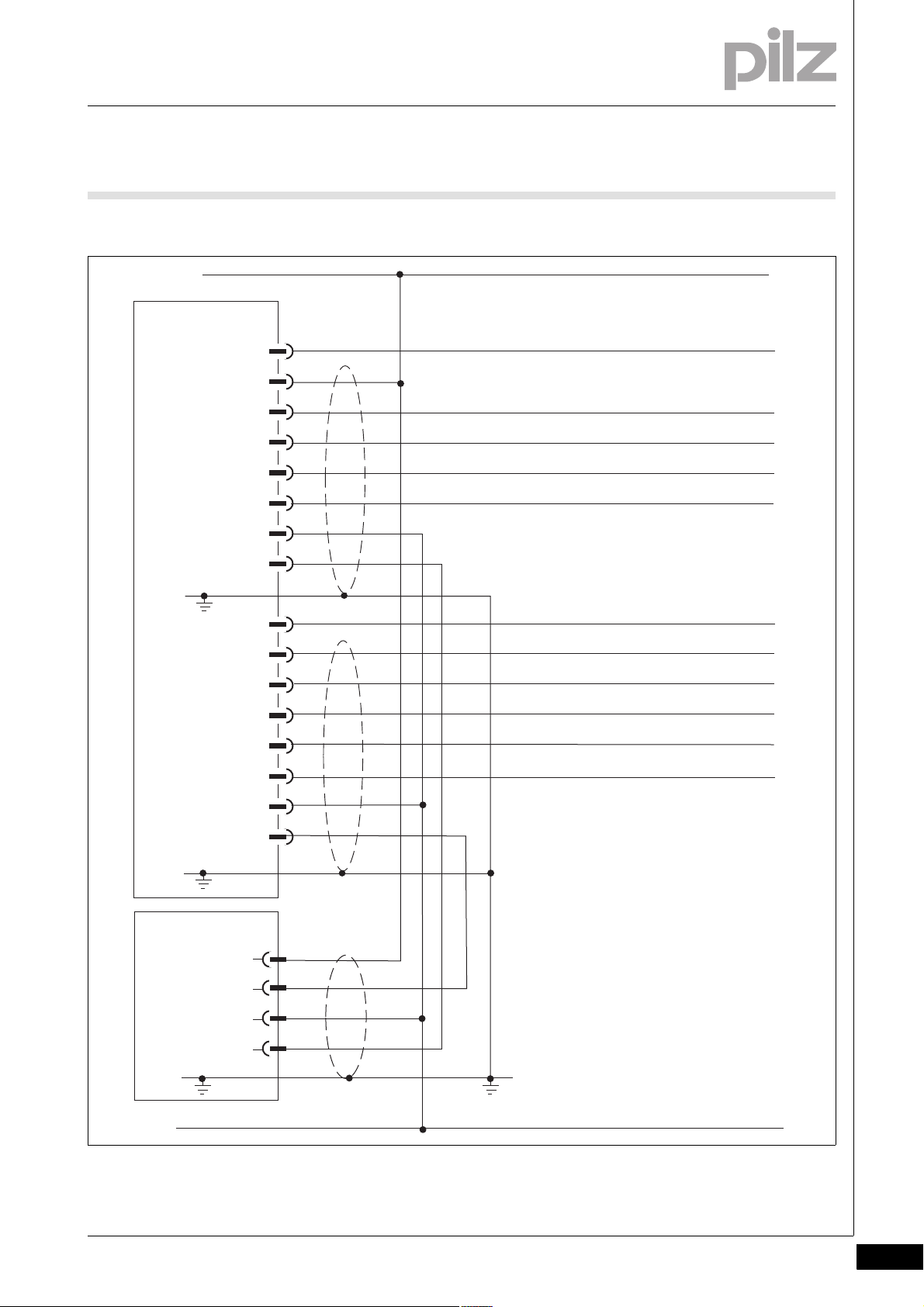
1
PSENvip
Receiver
X1
PSENvip
Transmitter
2
3
4
5
6
7
8
Protected field mode 1 / Tool class PLC -> PSENvip Bit 1
Protected field mode 2 / Tool class PLC -> PSENvip Bit 2 *)
OSSD 1
Mute 1 / Tool class PSENvip -> PLC Bit 1 *)
1
2
3
4
5
6
7
8
1
2
3
4
24 V DC
0 V
Power Off (Setup) / PLC Ready *)
Acknowledgement
System-Init
OSSD 2
TRM_ON
TRM_SYNC
TRM_ON
TRM_SYNC
X2
X3
Mute 2 / Tool class PSENvip -> PLC Bit 2 *)
Activate *)
Acknowledge PSENvip -> PLC *)
*) Used in communication between
PSENvip and safety system
6 Wiring
6.2 Connections
6.2.5 Connection diagram
Connection diagram6-Verdrahtung_Anschluss_Schema_dyn_mute
Fig. 6-6: Connection diagram
Pilz GmbH & Co. KG, Felix-Wankel-Straße 2, 73760 Ostfildern, Germany
Telephone: +49 711 3409-0, Telefax: +49 711 3409-133, E-Mail: pilz.gmbh@pilz.de
6-7
Page 82

6 Wiring
6-8
Pilz GmbH & Co. KG, Felix-Wankel-Straße 2, 73760 Ostfildern, Germany
Telephone: +49 711 3409-0, Telefax: +49 711 3409-133, E-Mail: pilz.gmbh@pilz.de
Page 83

7 Commissioning
7.1 Commissioning guidelines
77000CommissioningComm issioning7-7.1Commissioning guidelines7100Commissioning guidelines7-Inbetriebnahme_Hinweise
When commissioning for the first time, please note the following:
CAUTION!
Have the protective equipment tested and approved before
commissioning for the first time!
Any machine safeguarded by the PSENvip must be tested and
approved by qualified personnel before it is placed on the market. A test report must be generated and archived during initial
commissioning.
Please refer to the guidelines given in the chapter entitled
"Safety", under "Qualified Personnel".
Initial commissioning involves
Aligning the transmitter and receiver
Tracking the adjustment line to the tip of the upper tool
Entering the overrun
Performing the function test using the test piece
The tool change adjustment involves
Tracking the adjustment line to the tip of the upper tool
Performing the function test using the test piece
NOTICE
The tool change adjustment must also be made during initial
commissioning.
Pilz GmbH & Co. KG, Felix-Wankel-Straße 2, 73760 Ostfildern, Germany
Telephone: +49 711 3409-0, Telefax: +49 711 3409-133, E-Mail: pilz.gmbh@pilz.de
7-1
Page 84

7 Commissioning
7.2 Initial commissioning
7.2Initial commissioning7200Initial commissioning7-
7.2.1 Align transmitter and receiver
Align transmitter and receiver7-Inbetriebnahme_Erstinbetriebnahme_Ausrichten
Please note the following when aligning the transmitter and receiver:
Once installed, the transmitter and receiver must be exactly aligned
to each other and to the tip of the upper tool. The vertical and horizontal alignment is performed using adjustment templates and is displayed on the receiver.
The transmitter and receiver must also be aligned after changing ei-
ther the PSENvip transmitter or receiver.
7.2.1.1 Prepare for alignment
Prepare for alignment7-Inbetriebnahme_Erstinbetriebnahme_Ausrichtung_vorbereiten
Please note the following when preparing for alignment:
Transmitter and receiver must be installed correctly on the press
brake (see Chapter 5, "Installation") and electrically wired (see Chapter 6, "Wiring").
An upper tool must be fitted to the right and left-hand edge of the
press brake.
Switch on the supply to the PSENvip.
7.2.1.2 Adjustment templates
Adjustment templates7-Inbetriebnahme_Erstinbetriebnahme_Justageschablonen
Two adjustment templates and the information on the display provide
support when aligning the transmitter and receiver.
Please note the different cut-outs around the cross-hair on the two adjustment templates. On the left-hand adjustment template in the illustration below, the cross-hair is located within a square cutout. The different
forms make it easier to secure information about the direction of movement when aligning the transmitter and receiver.
7-2
Pilz GmbH & Co. KG, Felix-Wankel-Straße 2, 73760 Ostfildern, Germany
Telephone: +49 711 3409-0, Telefax: +49 711 3409-133, E-Mail: pilz.gmbh@pilz.de
Page 85

7 Commissioning
Magnet
Alignment grid
Magnet
Back gauge with notch
Cross-hair
7.2 Initial commissioning
Fig. 7-1: Adjustment templates (viewed from the magnet side)
You can select either adjustment template to attach to the transmitter or
receiver side.
7.2.1.3 Adjustment directions of transmitter and receiver
Adjustment directions of transmitter and receiver7-Inbetriebnahme_Erstinbetriebnahme_Verstellrichtungen
The PSENvip transmitter and receiver can be adjusted in three directions.
Fig. 7-2: Adjustment directions of transmitter and receiver
Pilz GmbH & Co. KG, Felix-Wankel-Straße 2, 73760 Ostfildern, Germany
Telephone: +49 711 3409-0, Telefax: +49 711 3409-133, E-Mail: pilz.gmbh@pilz.de
7-3
Page 86

7 Commissioning
7.2 Initial commissioning
Direction What?
A Move horizontally within the groove of the adjustment plate
B Rotate on a horizontal plane within the slot holes of the ad-
C Move vertically by adjusting the nuts on the bolts
Guidelines for the mechanical alignment of transmitter and receiver:
When making the alignment, the nuts on the bolt connecting the
PSENvip to the adjustment plate should only be hand-tightened.
There are three notches on the adjustment plate and auxiliary adjust-
ment plate for rotating the transmitter and receiver. The transmitter or
receiver is inserted into the slot holes on the adjustment plate (adjustment direction B).
Push the screwdriver blade into the middle notch of the auxiliary ad-
justment plate and adjustment plate.
Rotate the screwdriver blade in the required direction.
You can use the left or right-hand notch to rotate the transmitter or
receiver even further to the left or right.
justment plate
7-4
Fig. 7-3: Adjustment direction B
Pilz GmbH & Co. KG, Felix-Wankel-Straße 2, 73760 Ostfildern, Germany
Telephone: +49 711 3409-0, Telefax: +49 711 3409-133, E-Mail: pilz.gmbh@pilz.de
Page 87

7 Commissioning
Align the
alignment grid
on the upper
tool
Centre point of
the upper tool
in the notch on
the back stop
Illuminated target area
7.2 Initial commissioning
7.2.1.4 Align transmitter
Align transmitter7-Inbetriebnahme_Erstinbetriebnahme_Sender_ausrichten
Attach an adjustment template with magnets to the upper tool. The tip
of the upper tool must sit in the notch on the stop of the adjustment
template.
Align the alignment grid of the adjustment template to the contour of
the upper tool.
Fig. 7-4: Attach the adjustment template to the transmitter
The illuminated target area must completely envelop the receiver. If
you hold a white sheet of paper behind the receiver you will be able
to see the contours of the receiver better.
Fig. 7-5: Receiver illuminated by transmitter
If the illuminated target area does not enclose the receiver as shown
in the diagram, then you will need to realign the transmitter
Pilz GmbH & Co. KG, Felix-Wankel-Straße 2, 73760 Ostfildern, Germany
Telephone: +49 711 3409-0, Telefax: +49 711 3409-133, E-Mail: pilz.gmbh@pilz.de
7-5
Page 88

7 Commissioning
7.2 Initial commissioning
INFORMATION
Carefully align the illuminated target area to the receiver. This will
make the adjustments in the following work stages easier.
7.2.1.5 Tool shapes
Tool shapes7-Inbetriebnahme_Erstinbetriebnahme_Empfaenger_ausrichten_Werkzeuge_1
The correct adjustment of the upper tool also depends on the tool
shape. The tools are divided into tool classes in the Tool Change menu.
INFORMATION
You must comply with the tool class information provided in
Section 7.3 "Adjustment during tool change", "Tool detection"
Section entitled "Tool shapes", under "Safety"
"System Connections" chapter
in this chapter.
Inbetriebnahme_Erstinbetriebnahme_Empfaenger_ausrichten_Werkzeuge_2
During initial commissioning, the upper tool should be positioned in a
way that corresponds to the expected tool class.
Two bending lines are available on the PSENvip display for correct alignment of the various tool types. In the following examples, please note
that the maximum width of the respective tools for the tool class can be
achieved when the appropriate bending line is used.
7-6
Pilz GmbH & Co. KG, Felix-Wankel-Straße 2, 73760 Ostfildern, Germany
Telephone: +49 711 3409-0, Telefax: +49 711 3409-133, E-Mail: pilz.gmbh@pilz.de
Page 89

7 Commissioning
> 15 mm
< 15 mm
< 15 mm
7.2 Initial commissioning
Examples of the correct adjustment of various tool types:
Tool class 1: Pointed tools
For these tools we recommend alignment to
the left-hand bending line. The distance from
the bending line to the front segments of the
protected field is >15 mm.
Tool class 2: Semi-circular tools
For these tools we recommend alignment to
the left-hand bending line. The distance from
the front bending line of the tool to the front
segments of the protected field is <15 mm.
The rear bending line of the tool is detected
by the protected field. The position of the
front bending line must be considered in the
hazard analysis.
Tool class 2: Stamp
For these tools we recommend alignment to
the central bending line. The distance from
the front bending line of the tool to the front
segments of the protected field is <15 mm.
The rear bending line of the tool is detected
by the protected field. The position of the
front bending lines must be considered in the
hazard analysis.
Tool class 3: Stamp
The front and rear bending lines of the tool
are outside the protected field. The position
of the bending lines must be considered in
the hazard analysis.
Pilz GmbH & Co. KG, Felix-Wankel-Straße 2, 73760 Ostfildern, Germany
Telephone: +49 711 3409-0, Telefax: +49 711 3409-133, E-Mail: pilz.gmbh@pilz.de
7-7
Page 90

7 Commissioning
Align the
alignment grid
on the upper
tool
Centre point of
the upper tool
in the notch on
the back stop
7.2 Initial commissioning
7.2.1.6 Align receiver
Align receiver7-Inbetriebnahme_Erstinbetriebnahme_Empfaenger_ausrichten_1
Attach an adjustment template with magnets to the upper tool. The tip
of the upper tool must sit in the notch on the stop of the adjustment
template.
Align the alignment grid of the adjustment template to the contour of
the upper tool.
Inbetriebnahme_Erstinbetriebnahme_Empfaenger_ausrichten_Justagebild_1
Inbetriebnahme_Erstinbetriebnahme_Empfaenger_ausrichten_Justagebild_nicht_mittig_1
Fig. 7-6: Attach the adjustment template to the receiver
Press the <MODE> key.
Using the keys , select the Adjustment option.
Press the <ENTER> key to open the Adjustment option.
The adjustment image shown in the illustration below will appear on the
receiver display.
Please note that the bending line is approximately 7 mm to the left of the
centre of the display.
7-8
Pilz GmbH & Co. KG, Felix-Wankel-Straße 2, 73760 Ostfildern, Germany
Telephone: +49 711 3409-0, Telefax: +49 711 3409-133, E-Mail: pilz.gmbh@pilz.de
Page 91

7 Commissioning
7.2 Initial commissioning
Inbetriebnahme_Erstinbetriebnahme_Empfaenger_ausrichten_Justagebild_2
Inbetriebnahme_Erstinbetriebnahme_Empfaenger_ausrichten_Justagebild_nicht_mittig_2
Fig. 7-7: Adjustment image
The receiver is correctly aligned with the transmitter when:
The cross-hairs of both adjustment templates overlap
The quadrants form a full circle and
The centre point of the upper tool is on the bending line.
The correct adjustment image on the display will look like the image
shown in the illustration below.
Inbetriebnahme_Erstinbetriebnahme_Empfaenger_ausrichten_2
Fig. 7-8: Correct adjustment image
INFORMATION
The adjustment templates have different cut-outs around the
cross-hair (see section entitled "Adjustment templates"). This
makes it easier to evaluate the adjustment direction required by
the transmitter and receiver.
Pilz GmbH & Co. KG, Felix-Wankel-Straße 2, 73760 Ostfildern, Germany
Telephone: +49 711 3409-0, Telefax: +49 711 3409-133, E-Mail: pilz.gmbh@pilz.de
7-9
Page 92

7 Commissioning
7.2 Initial commissioning
Adjust the direction of the receiver as described in the section entitled
"Adjustment directions of transmitter and receiver".
Remove the adjustment templates.
The correct adjustment image on the display will look like the image
shown in the illustration below:
The bending line should be on the vertical guide.
The tool centre point should be aligned with the horizontal guide (the
horizontal guide is firmly in the middle of the range bar (see section
Inbetriebnahme_Erstinbetriebnahme_Empfaenger_ausrichten_3_nicht_mittig
entitled "Make adjustment during tool change").
Inbetriebnahme_Erstinbetriebnahme_Empfaenger_ausrichten_4
Inbetriebnahme_Erstinbetriebnahme_Empfaenger_ausrichten_5_nicht_mittig
Fig. 7-9: Correct adjustment image
Select <ENTER>.
A guide frame appears on the display. Apart from the areas around the
tool centre point, the guide frame should be clear of objects. The following diagram illustrates a valid and an an invalid adjustment image.
In the case of an invalid adjustment (right-hand diagram), the Out of ran-
ge message will also appear.
7-10
Pilz GmbH & Co. KG, Felix-Wankel-Straße 2, 73760 Ostfildern, Germany
Telephone: +49 711 3409-0, Telefax: +49 711 3409-133, E-Mail: pilz.gmbh@pilz.de
Page 93

7 Commissioning
Out of range
7.2 Initial commissioning
Fig. 7-10: Checking the adjustment image with superimposed guide
Inbetriebnahme_Erstinbetriebnahme_Empfaenger_ausrichten_6
You can switch to the adjustment image without guide frame by
pressing <ENTER> again.
Exit the adjustment using the <ESC> key.
frame
The transmitter and receiver are now mechanically aligned.
NOTICE
After you have aligned the transmitter and receiver you will still
need to carry out the step for "Adjustment during tool change"
(see section entitled "Adjustment during tool change").
7.2.2 Adjustment template with bracket
Adjustment template with bracket7-Inbetriebnahme_Erstinbetriebnahme_Justageschablone_mit_Traeger
An adjustment template screwed to a suitable bracket is also available
as an accessory. This bracket is not supplied with the system.
Fasten the template to the bracket using half length taper-grooved
dowel pins and cylinder head bolts (see illustration).
Pilz GmbH & Co. KG, Felix-Wankel-Straße 2, 73760 Ostfildern, Germany
Telephone: +49 711 3409-0, Telefax: +49 711 3409-133, E-Mail: pilz.gmbh@pilz.de
7-11
Page 94

7 Commissioning
10
45
65
Ø 3
+0,1
Ø 3,4
Ø 3,4
Ø 3
+0,1
1
3
2
1
7.2 Initial commissioning
Fig. 7-11: Adjustment template to attach to bracket
1: Ø 3 mm DIN 1472 half length taper-grooved dowel pin
2: M3 x 10 cylinder head bolts
3: Ø 3 mm DIN 1472 half length taper-grooved dowel pin
Attach the bracket to the upper tool clamp.
7-12
Fig. 7-12: Adjustment template with bracket
1: Bracket
Pilz GmbH & Co. KG, Felix-Wankel-Straße 2, 73760 Ostfildern, Germany
Telephone: +49 711 3409-0, Telefax: +49 711 3409-133, E-Mail: pilz.gmbh@pilz.de
INFORMATION
To align the transmitter and receiver, follow the same procedure
as outlined in the section entitled "Align transmitter and
receiver".
Page 95

7 Commissioning
7.3 Adjustment during tool change
7.3Adjustment during tool change7300Adjustm ent during tool change7-Inbetriebnahme_Justage_bei_Werkzeugwechsel
The adjustment line is automatically tracked to the tip of the tool. The
tracking of the adjustment line is shown on the display.
INFORMATION
Generally you should not have to mechanically realign the transmitter and receiver during a tool change.
CAUTION!
The manufacturer or operator of the press must ensure safe
selection of the "Adjustment during tool change" operating
mode with appropriate measures.
CAUTION!
The protective equipment must be tested following a tool
change adjustment!
Use the standardised test piece to perform a function test, see
section entitled "Function test of the safety device".
7.3.1 Prepare for adjustment during tool change
Prepare for adjustment during tool change7-Inbetriebnahme_Justage_bei_Werkzeugwechsel_vorbereiten
Transmitter and receiver must be exactly aligned to each other and to
the centre point of the upper tool, as described in the section entitled
"Initial commissioning".
The supply voltage must be present.
7.3.2 Tool detection
Tool detection7-Inbetriebnahme_Justage_bei_Werkzeugwechsel_Werkzeugerkennung
All tool shapes are permitted in principle (but please refer to the warnings in the section entitled "Tool shapes", under "Safety").
In TOOL CHANGE operating mode, the PSENvip detects the contour of
the tool and assigns it to a tool class.
Pilz GmbH & Co. KG, Felix-Wankel-Straße 2, 73760 Ostfildern, Germany
Telephone: +49 711 3409-0, Telefax: +49 711 3409-133, E-Mail: pilz.gmbh@pilz.de
7-13
Page 96

7 Commissioning
>15 mm
1
2
3
<15 mm
H3 V2H2 V3V1H1 B1
max. 32 mm
max. 25 mm
> 15 mm
> 15 mm
HHVV
7.3 Adjustment during tool change
Assignment to a tool class depends on
Compliance with the requirement from EN 12622, whereby the pro-
tected field must safeguard areas lying 15 mm before the front bending line.
Full or partial detection of the upper tool via the protected field.
Fig. 7-13: Classification of tools into tool classes
Tool class 1
The contour of these tools is fully detected by the PSENvip.
The front (V1 or B1) and rear (H1 or B1) bending lines are within the
protected field.
The front segments of the protected field are at least 15 mm away
from the front bending line.
These tools are safeguarded in compliance with the standards.
Example:
7-14
Pilz GmbH & Co. KG, Felix-Wankel-Straße 2, 73760 Ostfildern, Germany
Telephone: +49 711 3409-0, Telefax: +49 711 3409-133, E-Mail: pilz.gmbh@pilz.de
Fig. 7-14: Example for tool class 1
Page 97

7 Commissioning
> 25 mm
<15 mm
HV
HV
7.3 Adjustment during tool change
Tool class 2
The contour of these tools is fully detected by the PSENvip.
The front (V2) and rear (H2) bending lines are within the protected
field.
The front segments of the protected field are less than 15 mm away
from the front bending line.
These tools are not safeguarded in compliance with the standards.
Example:
Fig. 7-15: Example for tool class 2
Tool class 3
The contour of these tools is not fully detected by the PSENvip.
The front (V3) and/or rear (H3) bending lines are within the protected
field.
These tools are not safeguarded in compliance with the standards.
Example:
Pilz GmbH & Co. KG, Felix-Wankel-Straße 2, 73760 Ostfildern, Germany
Telephone: +49 711 3409-0, Telefax: +49 711 3409-133, E-Mail: pilz.gmbh@pilz.de
Fig. 7-16: Example for tool class 3
7-15
Page 98

7 Commissioning
SYSTEM OK
OSSD OFF
TOOL CHANGE
SYSTEM OK
OSSD OFF
TOOL CHANGE
SYSTEM OK
OSSD OFF
TOOL CHANGE
Tool class 1
Tool class 2
Tool class 3
7.3 Adjustment during tool change
The tools are displayed as follows on the PSENvip display:
7.3.3 Make adjustment during tool change
Make adjustment during tool change7-Inbetriebnahme_Justage_bei_Werkzeugwechsel_durchführen_1
Fig. 7-17: Tool detection on the PSENvip display
To achieve optimum results, the tool should be aligned to an appropriate
bending line during initial commissioning (see section entitled "Initial
commissioning").
There are two ways of starting the function "Adjustment during tool
change":
Option 1:
Press the <MODE> key.
Using the keys , select the Tool Change option.
Press the <ENTER> key to start the Tool Change.
7-16
Telephone: +49 711 3409-0, Telefax: +49 711 3409-133, E-Mail: pilz.gmbh@pilz.de
Pilz GmbH & Co. KG, Felix-Wankel-Straße 2, 73760 Ostfildern, Germany
Page 99

7 Commissioning
SYSTEM OK
OSSD OFF
TOOL CHANGE
À
Â
Á
Ä
Å
Tool class 1
Æ
Ã
7.3 Adjustment during tool change
Option 2:
Press the ( ) key to start the Tool Change.
Inbetriebnahme_Justage_bei_Werkzeugwechsel_durchführen_2
Fig. 7-18: Tool change menu
1: Tool centre point
2: Range bar
3: Adjustment line
4: Central and rear bending line
5: No tool identified or vertical position of tool centre point out-
side of the range bar
6: Receiver insufficiently lit by transmitter
7: Detected tool class
The adjustment line is automatically tracked to the tool centre point.
The vertical position of the tool centre point must be within the range
bar. Once the adjustment line is at the top or bottom of the range bar,
the following symbol appears: .
Pilz GmbH & Co. KG, Felix-Wankel-Straße 2, 73760 Ostfildern, Germany
Telephone: +49 711 3409-0, Telefax: +49 711 3409-133, E-Mail: pilz.gmbh@pilz.de
If the symbol appears on the display, there is a problem with the
lighting of the receiver by the transmitter:
Check that the transmitter and receiver are aligned correctly. The illu-
minated target area must completely envelop the receiver. If necessary, realign the transmitter (see section entitled "Align transmitter").
Remove any potential contamination on the lens of the transmitter or
receiver.
7-17
Page 100

7 Commissioning
7.3 Adjustment during tool change
The adjustment has been carried out correctly when none of the symbols appear:
Finish the adjustment using the <ENTER> key.
The PSENvip prompts you to confirm that you accept the new tool
data:
Within 3 seconds, press the key .
You can exit the menu at any time without confirming by pressing
<ESC>. In this case, the previous tool data will be retained.
7-18
Pilz GmbH & Co. KG, Felix-Wankel-Straße 2, 73760 Ostfildern, Germany
Telephone: +49 711 3409-0, Telefax: +49 711 3409-133, E-Mail: pilz.gmbh@pilz.de
 Loading...