

Page 1

21909-3FR-07
4 D Betriebsanleitung
4 GB Operating instructions
4 F Manuel d'utilisation
PSEN sl-1.0p
21909-3FR-07PSEN sl-1.0p
Sicheres Schutztürsystem PSENslock
1153871755
Das sichere Schutztürsystem erfüllt die Anforderungen nach
EN 60204-1
EN 60947-5-3: PDF-M zusammen mit dem
Betätiger (siehe Technische Daten).
EN 62061: SIL CL 3
EN ISO 13849-1. PL e und Kat. 4
Der Sicherheitsschalter darf nur mit dem zu-
gehörigen Betätiger verwendet werden (sie-
he Technische Daten).
Die Sicherheitsausgänge müssen 2-kanalig
weiterverarbeitet werden.
Zu Ihrer Sicherheit
547263243
Installieren und nehmen Sie das Gerät nur
dann in Betrieb, wenn Sie diese Betriebsan-
leitung gelesen und verstanden haben und
Sie mit den geltenden Vorschriften über Ar-
beitssicherheit und Unfallverhütung vertraut
sind.
Beachten Sie die VDE- sowie die örtlichen
Vorschriften, insbesondere hinsichtlich
Schutzmaßnahmen
Durch Öffnen des Gehäuses oder eigen-
mächtige Umbauten erlischt jegliche Ge-
währleistung.
777809547
Entfernen Sie die Schutzkappe erst unmittel-
bar vor Anschluss des Geräts.
1007068171
Wichtig!
Die Magnetoberfläche und die Gegenplatte
können sich erwärmen. Achten Sie bei der
Montage darauf, dass die Wärmeabfuhr ge-
währleistet ist.
Gerätemerkmale
1013887115
Transpondertechnik
1163990667
Gerätevarianten:
– PSEN sl-1.0p 1.1: codiert
– PSEN sl-1.0p 1.1 VA: codiert, Bodenplatte
und Betätiger aus Edelstahl
– PSEN sl-1.0p 2.1: vollcodiert
– PSEN sl-1.0p 2.2: unikat codiert
1013941387
zweikanaliger Betrieb
2 Sicherheitsausgänge
2 Eingänge für Reihenschaltung
1 Meldeausgang
magnetische Zuhaltung für Prozessschutz
1 Eingang zum Ein-/Ausschalten des Zuhal-
temagnets
LED-Anzeige für
– Versorgungsspannung/Fehler
– Tür geschlossen
– Zustand Eingänge
– Zustand magnetische Zuhaltung
8-poliger M12-Anschlussstecker
PSENslock safety gate system
The safety gate system meets the requirements
in accordance with
EN 60204-1
EN 60947-5-3: PDF-M in conjunction with
the actuator (see Technical Details).
EN 62061: SIL CL 3
EN ISO 13849-1. PL e and Cat. 4
The safety switch may only be used with the
corresponding actuator (see Technical De-
tails).
The safety outputs must use 2-channel
processing.
For your safety
Only install and commission the unit if you
have read and understood these operating
instructions and are familiar with the applica-
ble regulations for health and safety at work
and accident prevention.
Ensure VDE and local regulations are met,
especially those relating to safety.
Any guarantee is rendered invalid if the hous-
ing is opened or unauthorised modifications
are carried out.
Do not remove the protective cap until you
are just about to connect the unit.
Notice!
The magnet surface and counterplate may
heat up. When installing, make sure that
heat dissipation is guaranteed.
Unit features
Transponder technology
Unit types:
– PSEN sl-1.0p 1.1: Coded
– PSEN sl-1.0p 1.1 VA: Coded, stainless
steel base plate and actuator
– PSEN sl-1.0p 2.1: Fully coded
– PSEN sl-1.0p 2.2: Uniquely coded
Dual-channel operation
2 safety outputs
2 inputs for series connection
1 signal output
Magnetic guard locking for process protec-
tion
1 input to switch the locking magnet on/off
LEDs for
– Supply voltage/fault
– Gate closed
– State of the inputs
– State of the magnetic guard locking device
8-pin M12 connector
Système de sécurité pour protecteurs
mobiles PSENslock
Le système de sécurité pour protecteurs mobiles satisfait aux exigences des normes
EN 60204-1
EN 60947-5-3 : PDF-M avec l'actionneur
(voir les caractéristiques techniques).
EN 62061 : SIL CL 3
EN ISO 13849-1. PL e et cat. 4
Le capteur de sécurité doit être utilisé uni-
quement avec l'actionneur correspondant
(voir les caractéristiques techniques).
Les sorties de sécurité doivent être traitées par
2 canaux.
Pour votre sécurité
Vous n'installerez l'appareil et ne le mettrez
en service qu'après avoir lu et compris le
présent manuel d'utilisation et vous être fa-
miliarisé avec les prescriptions en vigueur
sur la sécurité du travail et la prévention des
accidents.
Respectez les normes locales ou VDE, parti-
culièrement en ce qui concerne la sécurité.
L'ouverture de l'appareil ou sa modification
annule automatiquement la garantie.
Veuillez retirer le cache de protection avant
de raccorder l'appareil.
Important !
La surface magnétique et la contreplaque
peuvent chauffer. Pour le montage, faites at-
tention à ce que l'évacuation de la chaleur
soit assurée.
Caractéristiques de l'appareil
Technique à transpondeur
Modèles d'appareils :
– PSEN sl-1.0p 1.1 : codé
– PSEN sl-1.0p 1.1 VA : codé, platine de
fond et actionneur en acier inoxydable
– PSEN sl-1.0p 2.1 : codé multiple
– PSEN sl-1.0p 2.2 : codé unique
Commande par 2 canaux
2 sorties de sécurité
2 entrées pour montage en série
1 sortie de signalisation
Interverrouillage magnétique pour la protec-
tion des process
1 entrée pour l'activation / la désactivation
de l'aimant d'interverrouillage
LED de visualisation pour
– tension d'alimentation / défauts
– protecteur mobile fermé
– état des entrées
– état de l'interverrouillage magnétique
Connecteur M12 à 8 broches
- 1 -
Page 2
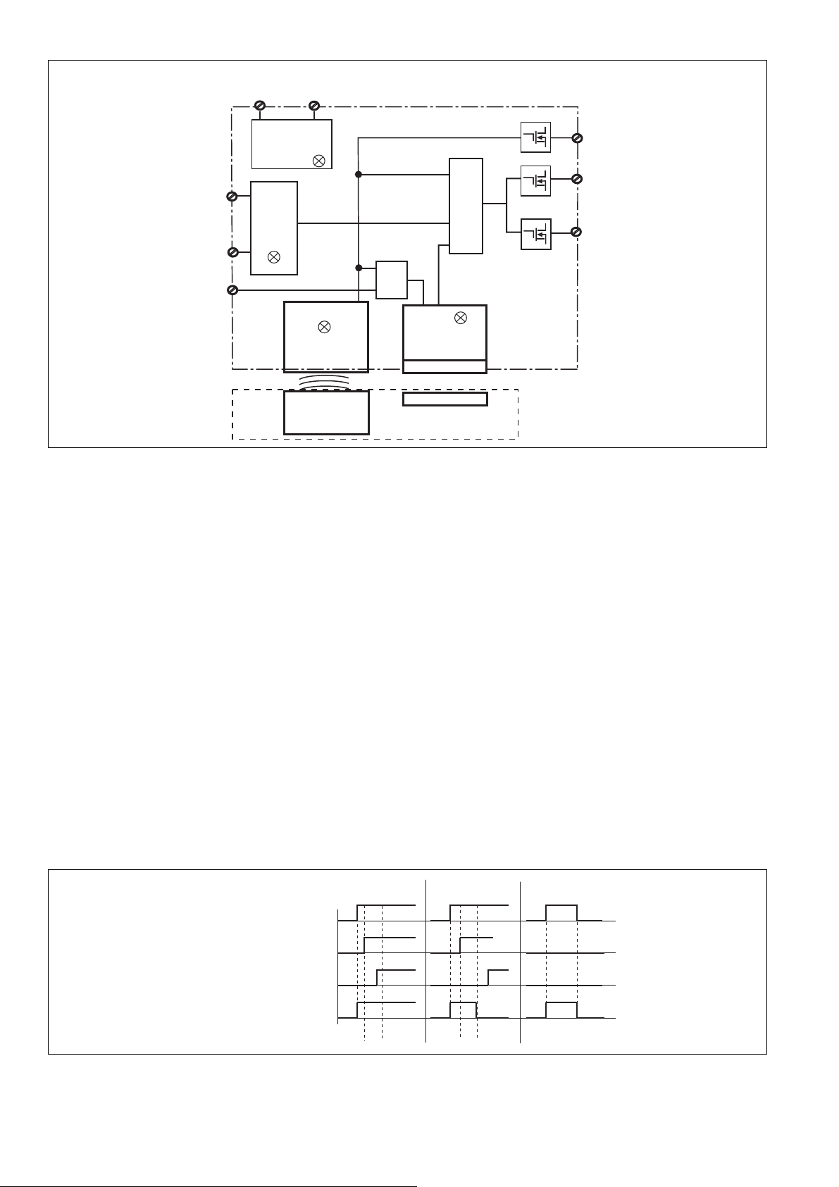
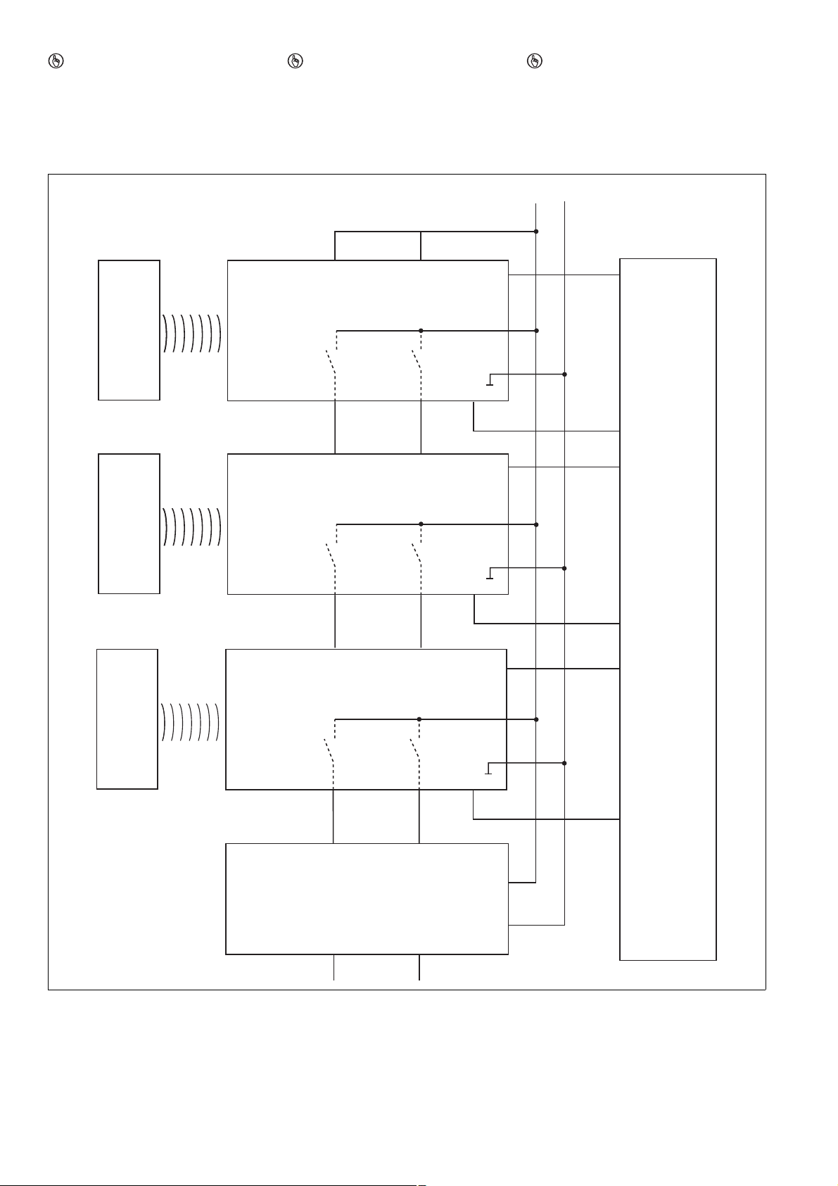
Blockschaltbild Block diagram Schéma de principe
Y32
S11
22
Empfänger
Receiver
Récepteur
Betätiger
Actuator
Actionneur
A1
A2
U
B
S21
12
Netzteil
Power supply
Alimentation
S31
Magnet
Magnet
Aimant
&
Input
&
Safety Gate
&
Power / Fault
Lock
Funktionsbeschreibung
1486993931
Sicherheitsausgänge
An den Sicherheitsausgängen 12 und 22 liegt
ein High-Signal, wenn gleichzeitig:
der Betätiger im Ansprechbereich ist.
(Schutztür geschlossen) und
die Eingänge S11 und S21 high sind und
der Eingang S31 high ist (Steuerbefehl für
magnetische Zuhaltung) und der Zuhaltema-
gnet eingeschaltet ist.
Die Sicherheitsausgänge 12 und 22 sind low,
wenn:
Der Betätiger sich außerhalb des Ansprech-
bereichs befindet oder
die Eingänge S11 und S21 low sind oder
der Eingang S31 low ist (Steuerbefehl für ma-
gnetische Zuhaltung) und der Zuhaltemagnet
ausgeschaltet ist
Wurden die Sicherheitsausgänge durch einen
der Eingänge S11 oder S21 abgeschaltet, dann
ist ein Wiedereinschalten nur möglich, nachdem beide Eingänge gleichzeitig low waren.
Die Sicherheitseingänge S11 und S21 werden
auf Plausibilität überwacht. Beide Eingänge
müssen gemeinsam aus- und einschalten (Teilbetätigungssperre).
1487004043
Meldeausgang
Der Meldeausgang Y32 meldet, ob der Betätiger im Ansprechbereich ist und ob die Haltekraft des Zuhaltemagneten nach 600 ms
erreicht wurde.
Safety gate
S31
Guard locking
Y32
Function description
Safety outputs
There is a high signal at safety output 12 and 22
if the following occur simultaneously:
The actuator is within the response range
(safety gate closed) and
Inputs S11 and S21 are high and
Input S31 is high (control command for mag-
netic guard locking) and the locking magnet
is switched on.
Safety outputs 12 and 22 are low if:
The actuator is outside the response range or
Inputs S11 and S21 are low or
Input S31 is low (control command for mag-
netic guard locking) and the locking magnet
is switched off.
If the safety outputs have been shut down by
either of the inputs S11 or S21, they cannot be
switched back on until both inputs are low simultaneously.
Safety inputs S11 and S21 are monitored for
feasibility. Both inputs must switch off and on
together (partial operation lock).
Signal output
The signal output Y32 signals whether the actuator is within the response range and whether
the holding force of the locking magnet has
been achieved after 600 ms.
①②③
closed
open
high
low
active
not active
high
low
tlock
tlock
Description du fonctionnement
Sorties de sécurité
Les sorties de sécurité 12 et 22 sont à « 1 » si,
simultanément :
l'actionneur se situe dans la zone de détec-
tion. (protecteur mobile fermé) et
les entrées S11 et S21 sont à « 1 » et
l'entrée S31 est à « 1 » (ordres de commande
avec interverrouillage magnétique) et
l'aimant d'interverrouillage est activé.
Les sorties de sécurité 12 et 22 sont à « 0 » si :
l'actionneur se trouve à l'extérieur de la zone
de détection ou si
les entrées S11 et S21 sont à « 0 » ou
l'entrée S31 est à « 0 » (ordres de commande
avec interverrouillage magnétique) et
l'aimant d'interverrouillage est désactivé.
Si les sorties de sécurité sont coupées par l'une
des entrées S11 ou S21, un redémarrage est
uniquement possible dès que les deux entrées
ont été à « 0 » en même temps.
La plausibilité des entrées de sécurité S11 et
S12 est surveillée. Les deux entrées doivent
être mises hors tension et sous tension simultanément (activation partielle).
Sortie de signalisation
La sortie de signalisation Y32 signale si l'actionneur se trouve dans la zone de détection et
si la force d'interverrouillage de l'aimant d'interverrouillage a été atteinte après 600 ms.
- 2 -
Page 3
1487029387
Lock
Safety Gate
Power Fault
Input
Seitenversatz/Lateral offset/
Décalage latéral
Höhenversatz/Vertical offset/Décalage vertical
1. Am Meldeausgang liegt ein High-Signal an,
wenn der Betätiger im Ansprechbereich ist
(Schutztür geschlossen). Der Meldeausgang
bleibt high, wenn
– an den Eingang S31 ein High-Signal ange-
legt wird (Zuhaltemagnet eingeschaltet)
und
– die Zuhaltekraft innerhalb von t
ms) aufgebaut werden konnte.
lock
(600
2. Der Meldeausgang wechselt nach low, wenn
der Aufbau der Zuhaltekraft t
überschreitet. Aus diesem Zustand kann der
(600 ms)
lock
Meldeausgang nur dann wieder nach high
wechseln, wenn am Eingang S31 erst ein
Low- und danach ein High-Signal angelegt
wird.
3. Der Meldeausgang wechselt nach low, wenn
der Betätiger den Ansprechbereich verlässt
(Schutztür geöffnet).
1090038795
Magnetische Zuhaltung und Magnetüberwachung
Der Zuhaltemagnet wird eingeschaltet, wenn
S31 high ist und der Betätiger erkannt wird
(Schutztür geschlossen).
Die Haltekraft des Zuhaltemagneten wird
beim Einschalten getestet. Wenn dieser Test
erfolgreich abgeschlossen ist, wechseln die
Sicherheitsausgänge in den High-Zustand.
Wird am eingeschalteten Zuhaltemagneten
Windungsunterbruch, oder Windungskurz-
1. There is a high signal at the signal output
when the actuator is within the response range (safety gate closed). The signal output
remains high if
– a high signal is present at the input S31
(locking magnet switched on)
and
– the holding force could be built up within
t
(600 ms).
lock
2. The signal output switches to low when the
build-up of the holding force exceeds t
(600 ms). From this status the signal output
lock
can only switch to high again when a low and
then a high signal is present at the input S31.
3. The signal output switches to low when the
actuator leaves the response range (safety
gate open).
Magnetic guard locking device and magnet monitoring
The locking magnet is switched on if S31 is
high and the actuator is detected (safety gate
closed).
The holding force of the locking magnet is
tested on power-up. If this test is completed
successfully, the safety outputs switch to a
high state.
If an open winding or a winding short circuit is
detected on a locking magnet that is switched
on, safety outputs 12 and 22 switch to a low
state.
1. La sortie de signalisation est à « 1 » si l'actionneur se trouve dans la zone de détection
(protecteur mobile fermé). La sortie de signalisation reste à « 1 » si
– l'entrée S31 est à « 1 » (aimant d'interver-
rouillage activé)
et si
– la force d'interverrouillage est créée en
l'espace de t
2. La sortie de signalisation passe à « 0 » si la
(600 ms).
lock
force d'interverrouillage dépasse t
(600 ms). À partir de cet état, la sortie de signalisation ne peut alors passer à « 1 » que si
l'entrée S31 est d'abord à « 0 » puis à « 1 ».
3. La sortie de signalisation passe à « 0 » si l'actionneur quitte la zone de détection (protecteur mobile ouvert).
Interverrouillage magnétique et surveillance magnétique
L'aimant d'interverrouillage est activé si S31
est à l'état « 1 » et si l'actionneur est détecté
(protecteur mobile fermé).
La force d'interverrouillage de l'aimant est
testée lors de l'activation. Si ce test a été effectué avec succès, les sorties de sécurité
passent à l'état « 1 ».
Si une coupure de la bobine ou un court-circuit
de la bobine est détecté sur l'aimant d'interverrouillage activé, les sorties de sécurité 12 et 22
passent à l'état « 0 ».
schluss erkannt, wechseln die Sicherheitsausgänge 12 und 22 in den Low-Zustand.
INFO
Wenn die Schutztür im zugehaltenen Zu-
INFORMATION
If the safety gate is in a locked condition
and is opened by force, the safety outputs
will shut down.
INFORMATION
Si le protecteur mobile en position fermée
est ouvert par la force, les sorties de sécu-
rité sont désactivées.
stand gewaltsam geöffnet wird, schalten
die Sicherheitsausgänge ab.
Seiten- und Höhenversatz Lateral and vertical offset Décalage latéral et en hauteur
lock
1077141515
Höhenversatz max. 5 mm
Seitenversatz max. 3 mm
Verdrahtung
1460809099
Beachten Sie:
Angaben im Abschnitt "Technische Daten"
unbedingt einhalten.
Hinweise zur Leitungslänge
1460805899
Die max. Leitungslänge ist abhängig vom
Spannungsabfall an den Leitungen zum Sensor. Die Höhe des Spannungsabfalls wird bestimmt durch:
den Leitungswiderstand
den Strom des Gerätes und der Strombela-
stung der Sicherheitsausgänge 12 und 22
Wird die minimal zulässige Versorgungsspannung am Stecker des Geräts unterschritten
(s. technische Daten), wird der Elektromagnet
nicht mehr zuverlässig angesteuert. Die LED
"Lock" meldet einen Fehler bei der Zuhaltung.
Vertical offset max. 5 mm
Lateral offset max. 3 mm
Wiring
Please note:
Information given in the "Technical details"
must be followed.
Guidelines for cable length
The max. cable length depends on the voltage
drop at the sensor cables. The level of voltage
drop is determined by the:
Cable resistance
Current of the device and the current load of
the safety outputs 12 and 22
If the level of the supply voltage at the device
connector falls below the minimum permitted
value (see Technical details), the electromagnet
is no longer activated reliably. The "Lock" LED
registers an error when guard locking.
- 3 -
Décalage en hauteur max. 5 mm
Décalage latéral max. 3 mm
Raccordement
Important :
Respecter impérativement les données indi-
quées dans le paragraphe « Caractéristiques
techniques ».
Remarques concernant la longueur des câbles
La longueur maximale des câbles dépend de la
chute de tension dans les câbles utilisés pour le
capteur. Le niveau de la chute de tension est
déterminée par :
la résistance du câble
le courant de l'appareil et la charge électri-
que des sorties de sécurité 12 et 22.
Si la tension d'alimentation minimale autorisée
est inférieure au connecteur de l'appareil (voir
les caractéristiques techniques), l'aimant électrique n'est plus commandé en toute fiabilité.
La LED « Lock » signale une erreur lors de l'interverrouillage.
Page 4
Mögliche Abhilfen:
1
2
3
4
8
5
6
7
Versorgungsspannung dauerhaft auf den
oberen Toleranzbereich (siehe technische
Daten) einstellen
höheren Leiterquerschnitt wählen
Last am Sicherheitsausgang reduzieren,
z. B. mit elektrischem Auswertegerät
(PNOZ e11p, 5 mA/Kanal)
Empfohlene Leiterquerschnitte
1487134091
Voraussetzung:
Versorgungsspannung: 24 V
Leitungstyp: LiYY 8x0,25 mm² (79 Ohm/km)
von Pilz
Possible remedies:
Set the supply voltage constantly to the up-
per tolerance range (see Technical details)
Select a higher cable cross section
Reduce the load on the safety output, e.g.
with an electrical evaluation device
(PNOZ e11p, 5 mA/channel)
Recommended cable cross sections
Prerequisite:
Supply voltage: 24 V
Cable type: LiYY 8x0.25 mm² (79 Ohm/km)
from Pilz
Remèdes possibles :
Paramétrer la tension d'alimentation dura-
blement sur la plage de tolérance supérieure
(voir les caractéristiques techniques)
Sélectionner une section du fil plus impor-
tante
Réduire la charge sur la sortie de sécurité,
par exemple, avec une unité de contrôle
électrique (PNOZ e11p, 5 mA/canal)
Section des câbles recommandée
Conditions préalables :
Tension d'alimentation : 24 V
Type de câble : LiYY 8x0,25 mm² (79 Ohm/
km) de Pilz
Max. Last pro Sicherheitsausgang/Max. load per safety output/Charge max. par
sortie de sécurité
Leitungslänge
1463471755
Wenn Leitungslängen größer als in der Tabelle
angegeben benötigt werden, dann nehmen Sie
bitte Kontakt mit Pilz auf.
/Cable length/Longueur du câble 45 m 24 m
If cable lengths greater than those stated in the
table are required, please contact Pilz.
100 mA 500 mA
Si des longueurs de câbles plus grandes que
celles indiquées dans le tableau sont nécessaires, veuillez prendre contact avec Pilz.
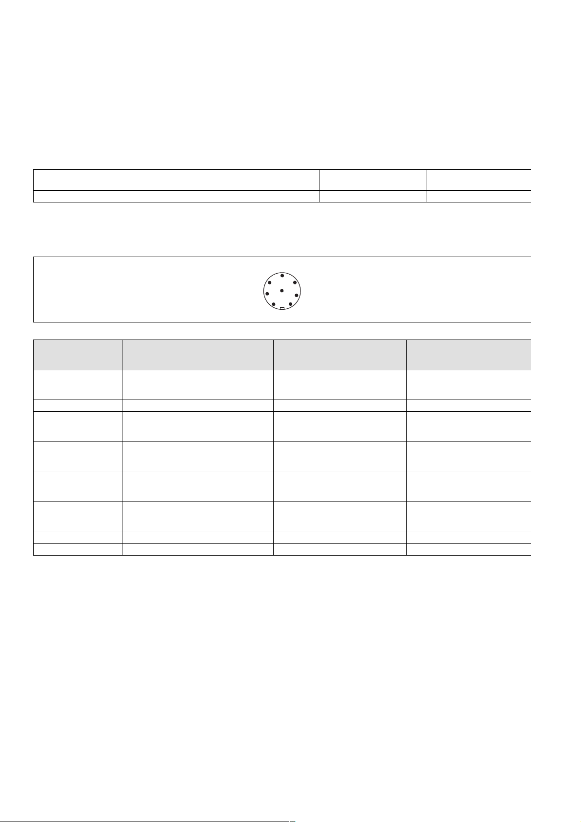
Anschlüsse Connections Raccordements
Stiftstecker 8-pol. M12 Connector 8 pin M12 Connecteur mâle M12 à 8 pôles
Anschlussbelegung Pin assignment Affectation des bornes
PIN/
Broche
1 Eingang Kanal 2/
2 +24 UB A1 braun/brown/marron
3 Ausgang Kanal 1/
4 Ausgang Kanal 2/
5 Meldeausgang "Lock"/
6 Eingang Kanal 1/
7 0 V UB A2 blau/blue/bleu
8 "Lock_Unlock" S31 rot/red/rouge
Funktion/
Function/
Foncion
Input, channel 2/
Canal d'entrée 2
Output, channel 1/
Canal de sortie 1
Output, channel 2/
Canal de sortie 2
Signal output "Lock"/
Sortie message "Lock"
Input, channel 1/
Canal d'entrée 1
Klemmenbezeichnung/
Terminal designation/
Désignation des bornes
S21 weiß/white/blanc
12 grün/green/vert
22 gelb/yellow/jaune
Y32 grau/grey/gris
S11 rosa/pink/rose
Adernfarbe (Pilz Kabel)/
Cable colour (Cable Pilz)/
Couleur du fil (fil de Pilz)
- 4 -
Page 5
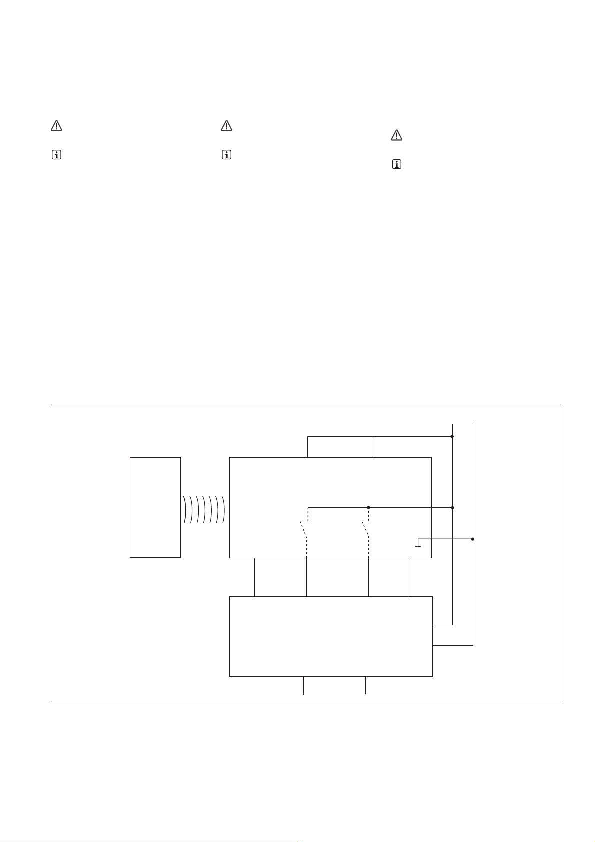
Anschluss an Auswertegeräte
S21
S11
12
22
24 V
0 V
I1 (FS)
I2 (FS)
A1
A2
A1
A2
Empfänger/
Reciever/
Recépteur
Betätiger/
Actuator/
Actioneur
S31
O1 (ST)
Y32
I1 (ST)
Auswertegerät/
Evaluation device/
Appareil de surveillance
FS: Fail-safe
ST: Standard
1104750091
Bitte beachten Sie:
das Netzteil muss den Vorschriften für Klein-
spannungen mit sicherer Trennung (SELV,
PELV) entsprechen.
die Ein- und Ausgänge des Sicherheitsschal-
ters müssen eine sichere Trennung zu Spannungen über 60 V AC besitzen.
1090417163
ACHTUNG!
Die Sicherheitsausgänge müssen 2-ka-
nalig weiterverarbeitet werden.
1067372427
INFO
Sicherheitsschaltgeräte mit Weitspannungsnetzteil oder in der Geräte-Variante
AC haben eine interne Potentialtrennung
und sind als Auswertegeräte nicht geeignet. Geeignet sind ausschließlich Sicherheitsschaltgeräte mit einer
Versorgungsspannung von 24 V DC.
Bei Sicherheitsschaltgeräten, bei denen es
Varianten mit Weitspannungsnetzteil gibt,
werden deshalb nur die Bestell-Nr. der Geräte-Varianten mit 24 V DC Versorgungsspannung aufgeführt.Bei mit "*"
versehenen Bestell-Nr. können die Sicherheitsschaltgeräte mit einer Versorgungsspannung von 24 V DC oder 24 V AC
betrieben werden. Diese Sicherheitsschaltgeräte dürfen aber ausschließlich nur mit
24 V DC Versorgungsspannung betrieben
werden.
Connection to evaluation devices
Please note:
The power supply must meet the regulations
for extra low voltages with safe separation
(SELV, PELV).
the inputs and outputs of the safety switch
must have a safe separation to voltages over
60 V AC.
CAUTION!
The safety outputs must use 2-channel
processing.
INFORMATION
Safety relays with universal power supply
or in AC unit versions have internal potential isolation and are not suitable as evaluation devices. Only safety relays with a
24 VDC supply voltage are suitable.
For this reason, where safety relays have
versions with a universal power supply,
only those order numbers for unit versions
with 24 VDC supply voltage are listed.Where order numbers are marked with
"*", the safety relays can be operated with
a supply voltage of 24 VDC or 24 VAC.
However, these safety relays may only be
operated with 24 VDC supply voltage.
Raccordement aux appareils de contrôle
Tenez compte de ce qui suit :
Cette alimentation doit être conforme aux
prescriptions relatives aux basses tensions à
séparation galvanique (SELV, PELV).
Les entrées et les sorties du capteur de sé-
curité doivent posséder une séparation gal-
vanique pour les tensions supérieures à
60 V AC.
ATTENTION !
Les sorties de sécurité doivent être traitées par 2 canaux.
INFORMATION
Les blocs logiques de sécurité avec alimentation universelle ou les variantes d'appareils AC disposent d'une isolation
galvanique interne et ne conviennent pas
en tant qu'unités de contrôle. Seuls les
blocs logiques de sécurité avec une tension d'alimentation de 24 V DC sont compatibles.
Pour les blocs logiques de sécurité qui disposent de modèles avec alimentation universelle, on répertorie uniquement la
référence des modèles d'appareils dont la
tension d'alimentation est de 24 V DC.Si les
références sont suivies de "*", les blocs logiques de sécurité peuvent être exploités
avec une tension d'alimentation de 24 V DC
ou 24 V AC. Néanmoins, ces blocs logiques
de sécurité ne doivent être exploités
qu'avec une tension d'alimentation de
24 V DC.
Einzelschaltung Single connection Montage simple
- 5 -
Page 6
Reihenschaltung
S21
S11
24 V
0 V
A1
A2
12
22
A1
A2
Auswertegerät/
Evaluation device/
Appareil de surveillance
12 22
A1
A2
12 22
Betätiger/Actuator/
Actionneur
A1
A2
S21
S11
S21
S11
PLC
Y32
Y32
Y32
Betätiger/Actuator/
Actionneur
Betätiger/Actuator/
Actionneur
Empfänger/Receiver/
Récepteur
Empfänger/Receiver/
Récepteur
Empfänger/Receiver/
Récepteur
S31
S31
S31
I1 (FS)
I2 (FS)
FS: Fail-safe
ST: Standard
O1 (ST)
I1 (ST)
O2 (ST)
O3 (ST)
I2 (ST)
I3 (ST)
1484998667
WICHTIG
Bei Reihenschaltung mehrerer Geräte addiert sich mit der Anzahl der zwischengeschalteten Sicherheitsschalter
die Rückfallverzögerung
der max. Magnetstrom (s. technische
Daten)
Series connection
NOTICE
When several units are connected in series,
the number of interconnected safety
switches adds together.
The delay-on de-energisation
The max. solenoid current (see Technical
details)
Montage en série
IMPORTANT
Si plusieurs appareils sont montés en série,
les éléments suivants augmentent avec le
nombre de capteurs de sécurité montés
le temps de retombée
le courant magnétique max. (voir les ca-
ractéristiques techniques)
- 6 -
Page 7

Anschluss an PNOZ X, PNOZpower, PNOZ-
PNOZ X2.7P (No. 777 305*, 787 305*)
PNOZ X2.8P (No. 777 301*, 787 301*)
PNOZ X4 (No. 774 730)
PNOZ X8P (No. 777 760, 787 760)
PNOZ X9P (No. 777 609, 787 609)
A1
A2
2
7
S12
S52
3
4
5
8
6
1
24 V
0 V
A1
A2
12
22
Y32
S31
S11
S21
S21
S22
PNOZ
PSENslock
PNOZ X3P (No. 777 310*, 787 310*)
PNOZ X3.10P (No. 777 314*, 787 314*)
PNOZ XV3P
PNOZ XV3.1P (No. 777 520, 787 520, 777 522, 787 522, 777525)
A1
A2
2
7
S12
S32
3
4
5
8
6
1
24 V
0 V
A1
A2
12
22
Y32
S31
S11
S21
S21
S22
PNOZ
PSENslock
PNOZ s3
PNOZ s4 (No. 750 104, 751 104)
PNOZ s4.1 (No. 750 124, 751 124)
PNOZ s5 (No. 750 105, 751 105, 751 185)
PNOZ X5 (No. 774 325*)
A1
A2
2
7
S12
S22
3
4
5
8
6
1
24 V
0 V
A1
A2
12
22
Y32
S31
S11
S21
PNOZ
PSENslock
PNOZ X2.9P
A1
A2
2
7
S12
S52
3
4
5
8
6
1
24 V
0 V
A1
A2
12
22
Y32
S31
S11
S21
PNOZ
PSENslock
sigma, PNOZelog
Connection to PNOZ X, PNOZpower,
PNOZsigma, PNOZelog
Raccordement aux PNOZ X, PNOZpower,
PNOZsigma, PNOZelog
- 7 -
Page 8

Anschluss an PNOZmulti Connection to PNOZmulti Raccordement au PNOZmulti
PNOZ X10.1 (No. 774 749)
PNOZ X10.11P
A1
A2
2
7
S12
Y3
3
4
5
8
6
1
24 V
0 V
A1
A2
12
22
Y32
S31
S11
S21
S21
S22
PNOZ
PSENslock
PNOZ e1.1p
PNOZ e1vp
PNOZ e6.1p
PNOZ e6vp
A1
A2
2
7
S12
S22
3
4
5
8
6
1
24 V
0 V
A1
A2
12
22
Y32
S31
S11
S21
Y4
S11
PNOZ
PSENslock
PNOZ e5.11p
PNOZ e5.13p
A1
A2
2
7
S12
S22
3
4
5
8
6
1
24 V
0 V
A1
A2
12
22
Y32
S31
S11
S21
Y37
S11
PNOZ
PSENslock
Schutztür/safety gate/protecteur mobile
Schaltertyp 3/switch type 3/type du capteur 3
I0, I1: Eingänge OSSD/inputs OSSD/entrées OSSD
I2: Meldeeingang/signal input/entrée d'information
O1: Lock / Unlock
Schutztür/safety gate/protecteur mobile
Standardbaustein SB64/standard block SB64/
bloc standard SB64
I00, I01: Eingänge OSSD/inputs OSSD/entrées OSSD
I02: Meldeeingang/signal input/entrée d'information
O00: Lock / Unlock
Anschluss an PSS Connection to PSS Raccordement au PSS
3
4
8
5
3
4
8
5
- 8 -
Page 9

Einlernen des Betätigers Teaching in the actuator Programmation de l'actionneur par ap-
prentissage
PSEN sl-1.0p 1.1
1175993995
Es wird jeder zugehörige Betätiger von Pilz (siehe Technische Daten) erkannt, sobald er in den
Ansprechbereich gebracht wird.
PSEN sl-1.0p 2.1
1175997707
Erstmaliges Einlernen des Betätigers:
Der erste vom Sicherheitsschalter erkannte zugehörige Betätiger (siehe Technische Daten)
wird automatisch eingelernt, sobald er in den
Ansprechbereich gebracht wird.
PSEN sl-1.0p 1.1
Any corresponding Pilz actuator (see Technical
Details) is detected as soon as it is brought into
the response range.
PSEN sl-1.0p 2.1
Teaching in the actuator for the first time:
The first corresponding actuator to be detected
by the safety switch (see Technical Details) is
taught in automatically as soon as it is brought
into the response range.
PSEN sl-1.0p 1.1
Chaque actionneur de Pilz (voir les caractéristiques techniques) est détecté dès qu'il est entre
dans la zone de déclenchement.
PSEN sl-1.0p 2.1
Première programmation de l'actionneur :
Le premier actionneur (voir les caractéristiques
techniques) détecté par le capteur de sécurité
est automatiquement programmé dès qu'il entre dans la zone de déclenchement.
Einlernen eines neuen Betätigers:
Bringen Sie den einzulernenden Betätiger als
einzigen Transponder in den Ansprechbereich des Sicherheitsschalters. Sobald der
Betätiger erkannt wird, wechselt die LED
"Safety Gate" auf gelbes Blinklicht.
Nach einer Wartezeit von 20 s wechselt die
LED "Safety Gate" auf gelbes Blitzen. Lösen
Sie innerhalb der nächsten 120 s durch Unterbrechen der Stromversorgung einen Systemreset aus.
Nach Wiedereinschalten des Geräts ist der
Lernvorgang erfolgreich beendet und die Anzahl noch erlaubter weiterer Lernvorgänge
wird um 1 vermindert.
Es sind maximal 8 Lernvorgänge möglich.
WICHTIG
Der Betätiger darf während des Einlernvorgangs nicht entfernt werden.
INFO
Ein erneutes Einlernen dieses Betätigers
am selben Sicherheitsschalter ist nicht
mehr möglich.
PSEN sl-1.0p 2.2
1176000651
Der erste vom Sicherheitsschalter erkannte zugehörige Betätiger (siehe Technische Daten)
wird automatisch eingelernt, sobald er in den
Ansprechbereich gebracht wird.
WICHTIG
Nach dem Einlernen des Betätigers kann
kein weiterer Betätiger mehr eingelernt
werden.
To teach in a new actuator:
The actuator that is to be taught in must be
brought into the safety switch's response
range as the only transponder. As soon as
the actuator is detected, the "Safety Gate"
LED switches to a yellow flashing light.
After 20 s has elapsed, the "Safety Gate"
LED switches to quick yellow flashes. Trigger
a system reset in the next 120 s by interrupting the power supply.
When the device is switched back on, the
learning procedure is complete and the
number of permitted additional learning procedures is reduced by 1.
A maximum of 8 learning procedures are
possible.
NOTICE
The actuator must not be removed during
the learning procedure.
INFORMATION
This actuator cannot be retaught on the
same safety switch.
PSEN sl-1.0p 2.2
The first corresponding actuator to be detected
by the safety switch (see Technical Details) is
taught in automatically as soon as it is brought
into the response range.
NOTICE
No other actuator may be taught in once
this actuator has been taught.
Programmation d'un nouvel actionneur :
Amenez l'actionneur à programmer dans la
zone de déclenchement du capteur de sécu-
rité. Aucun autre transpondeur ne doit se
trouver dans cette zone. Dès que l'action-
neur est détecté, la LED « Safety Gate »
commence à clignoter en jaune.
Après un délai d'attente de 20 s, la LED
« Safety Gate » commence à émettre des
flashs jaunes. Dans les 120 s qui suivent, dé-
clenchez une remise à zéro du système en
coupant l'alimentation électrique.
Le processus d'apprentissage est terminé
avec succès lorsque vous remettez l'appareil
sous tension. Le nombre de processus d'ap-
prentissage encore autorisés est alors réduit
de 1.
8 processus d'apprentissage au maximum
sont possibles.
IMPORTANT
Ne pas retirer l'actionneur de la zone de déclenchement durant le processus d'apprentissage.
INFORMATION
Une nouvelle programmation de cet actionneur sur le même capteur de sécurité n'est
plus possible.
PSEN sl-1.0p 2.2
Le premier actionneur (voir les caractéristiques
techniques) détecté par le capteur de sécurité
est automatiquement programmé dès qu'il entre dans la zone de déclenchement.
IMPORTANT
Dès que l'actionneur est programmé, il
n'est plus possible d'en programmer un
autre.
- 9 -
Page 10

Montage
800274059
Berücksichtigen Sie bei der Montage die An-
forderungen der DIN EN 1088.
Das sichere Schutztürsystem kann an
Schwenktüren mit Links- oder Rechtsanschlag oder an Schiebetüren montiert werden.
WARNUNG!
Möglicher Verlust der Sicherheitsfunktion durch grobe Manipulation!
Abhängig von der Anwendung können
schwerste Körperverletzungen und Tod
verursacht werden.
Verhindern Sie durch entsprechende Einbaumaßnahmen, dass
die Verdrahtung verändert werden kann
oder
ein Kurzschluss am Stecker erzeugt wer-
den kann.
Verhindern Sie auch, dass die Schutztür
mithilfe eines zweiten Betätigers geöffnet
werden kann.
Montieren Sie Sicherheitsschalter und Betä-
tiger parallel gegenüberliegend.
Befestigen Sie den Betätiger unlösbar mit Si-
cherheitsschrauben oder Nieten.
ACHTUNG!
Eine Umgebung mit elektrischen oder magnetisch leitfähigem Material kann die Geräteeigenschaften beeinflussen. Prüfen Sie
die Schaltabstände und den gesicherten
Ausschaltabstand.
1209719307
INFO
Montagewinkel sind als Zubehör erhältlich.
Installation
When installing make sure you comply with
the requirements of DIN EN 1088.
The safety gate system can be installed on
left or right-hinged swing gates or on sliding
gates.
WARNING!
Potential loss of safety function due to
gross manipulation!
Depending on the application, serious injury or death may result.
Use appropriate installation measures to
prevent
The wiring being modified or
A short circuit being generated on the
connector.
You should also prevent the possibility of
using a second actuator to open the
safety gate.
The safety switch and actuator should be in-
stalled opposite each other in parallel.
The actuator should be secured permanently
using safety screws or rivets.
CAUTION!
The unit's properties may be affected if installed in an environment containing electrical or magnetically conductive material.
Please check the operating distances and
the assured release distance.
INFORMATION
Mounting brackets are available as accessories.
Montage
Lors du montage, veuillez tenir compte des
exigences de la norme DIN EN 1088.
Le système de sécurité pour protecteurs mo-
biles peut être monté sur des portes battantes, gauche ou droite, ou sur des portes
coulissantes.
AVERTISSEMENT !
Perte possible de la fonction de sécurité
en cas de fraude grossière !
En fonction de l'application, cela peut provoquer de graves blessures corporelles,
voire la mort.
Empêchez par des mesures de montage
correspondantes
que le câblage puisse être modifié ou
qu'un court-circuit puisse se produire au
niveau du connecteur.
Empêchez également qu'un protecteur
mobile puisse être ouvert à l'aide d'un
deuxième actionneur.
Montez le capteur de sécurité et l'actionneur
face à face en parallèle.
Fixez l'actionneur à l'aide de vis de sécurité
ou de rivets, de sorte que son démontage
soit impossible.
ATTENTION !
Un environnement électrique ou magnétique peut influencer les caractéristiques des
appareils. Vérifiez les distances de commutation et la distance de déclenchement de
sécurité.
INFORMATION
Les équerres de montage sont disponibles
en tant qu'accessoires.
- 10 -
Page 11

Hinweis zum BetätigerPSEN sl-1.0fm
1462009611
Die Betätiger sind mit einer beweglichen Metallplatte ausgestattet. Deshalb muss im Befestigungsuntergrund eine Vertiefung für die
Schraubverbindung vorgesehen werden.
B ( 2 : 1 )
0
1
P
3
Note regarding the actuator PSEN sl-1.0fm
The actuators are fitted with a movable metal
plate. For this reason, a recess must be provided in the mounting surface for the screw connection.
Remarques concernant l’actionneur
PSEN sl-1.0fm
Les actionneurs sont équipés d'une plaque de
métal. C'est pourquoi il faut prévoir dans la
base de fixation une certaine profondeur pour
l'assemblage des vis.
B
1462017419
WARNUNG!
Gefahr von Tod und schwersten Verlet-
zungen durch Hineingreifen in den Gefahrenbereich!
Die Betätiger ermöglichen das Schließen
einer verzogenen Tür. Dadurch kann ein
Türspalt entstehen. Sorgen Sie dafür, dass
der Türspalt so klein bleibt, dass ein Hineingreifen in den Gefahrenbereich nicht möglich ist.
6
1
1
WARNING!
Risk of death and serious injury by
reaching into the danger zone!
The actuators enable a warped gate to be
closed. A gap may occur on the gate as a
result. Make sure that the gap remains
small enough to exclude the possibility of
reaching into the danger zone.
AVERTISSEMENT !
Danger de mort et lésions très graves en
cas de pénétration dans la zone dangereuse !
L'actionneur permet la fermeture d'un protecteur mobile endommagé. Il peut donc y
avoir une fente dans la porte. Assurez-vous
que la fente de la porte reste la plus petite
possible de manière à ce qu'elle ne permette pas d'accéder à la zone dangereuse.
- 11 -
Page 12

An Schwenktür montieren
1
3
2
4
1059870603
1. Betätiger auf gewünschte Höhe an Türkante
bündig ausrichten und Schrauben festziehen.
2. Tür schließen.
3. Montagewinkel an Sensor bündig ausrichten
und Schrauben festziehen.
4. Sensor mit Montagewinkel an Betätiger ausrichten und Schrauben festziehen.
Installing on a swing gate
1. Align the actuator flush with the edge of the
gate at the height required and tighten the
screws.
2. Close gate.
3. Align the mounting bracket flush with the
sensor and tighten the screws.
4. Align the sensor and mounting bracket with
the actuator and tighten the screws.
Montage sur porte à battants
1. Aligner l'actionneur sur le bord de la porte à
la hauteur souhaitée et serrer les vis à fond.
2. Fermer la porte.
3. Aligner l'équerre de montage sur le bord du
capteur et serrer les vis à fond.
4. Aligner le capteur et l'équerre de montage
sur l'actionneur et serrer les vis à fond.
- 12 -
Page 13

An Schiebetür montieren
1
3
2
5
6
4
(a)
(b)
(c)
1077138699
1. Montagewinkel für Betätiger an Schiebetür
bündig ausrichten und Schrauben festziehen.
2. Betätiger auf gewünschte Höhe montie-
ren.
3. Montagewinkel für Sensor am Rahmen
bündig ausrichten und mit Schrauben befestigen. (Wichtig: Schrauben nicht fest anziehen)
4. Tür schließen und Montagewinkel zuein-
ander ausrichten. Sensor aufgestellt mit
Montagewinkel an Betätiger drücken (a) und
Schraube (b) festziehen.
5. Sensor entfernen und Schraube (c) festzie-
hen.
6. Sensor zu Betätiger ausrichten und
Schrauben festziehen.
Installing on a sliding gate
1. Align the actuator mounting bracket flush
with the sliding gate and tighten the screws.
2. Install the actuator at the height required.
3. Align the sensor mounting bracket flush
with the frame and fasten with screws. (Important: do not tighten the screws)
4. Close the gate and align the mounting
plates. Place the sensor on the mounting
bracket, press the assembly against the actuator (a) and tighten screw (b).
5. Remove the sensor and tighten screw (c).
6. Align the sensor to the actuator and tight-
en the screws.
Montage sur porte coulissante
1. Aligner l'équerre de montage de l'action-
neur sur le bord de la porte coulissante et
serrer les vis à fond.
2. Monter l'actionneur à la hauteur souhaitée.
3. Aligner l'équerre de montage du capteur
sur le bord du cadre et fixer avec des vis.
(Important : ne pas serrer les vis à fond).
4. Fermer le protecteur mobile et l'aligner
avec l'équerre de montage. Appuyer le capteur placé avec l'équerre de montage sur
l'actionneur (a) et serrer la vis (b) à fond.
5. Retirer le capteur et serrer la vis (c) à fond.
6. Aligner le capteur sur l'actionner et serrer
les vis à fond.
Justage
814438667
Die angegebenen Schaltabstände (siehe technische Daten) gelten nur, wenn Sicherheitsschalter und Betätiger parallel
gegenüberliegend montiert sind. Andere Anordnungen können zu abweichenden Schaltabständen führen. Beachten Sie den maximal
zulässigen Seiten- und Höhenversatz (siehe
„Schaltabstände“ und „Max. Seiten- und Höhenversatz“).
Adjustment
The stated operating distances (see Technical
details) only apply when the safety switch and
actuator are installed facing each other in parallel. Operating distances may deviate if other
arrangements are used. Note the maximum
permitted lateral and vertical offset (see "Operating distances" and "Max. lateral and vertical
offset").
- 13 -
Ajustement
Les distances de commutation mentionnées
dans les caractéristiques techniques sont valables uniquement lorsque le capteur de sécurité
et l'actionneur sont montés l'un en face de
l'autre de manière parallèle. D'autres montages
peuvent conduire à des distances de commutation divergentes. Respectez le décalage latéral et vertical maximal autorisé (voir "Distances
de commutation" et "Décalage latéral et vertical maximum").
Page 14

Betrieb
800695819
Prüfen Sie vor der Inbetriebnahme die Funktion des Sicherheitsschalters.
Abweichungen zu den in dieser Bedienungsanleitung beschriebenen Eigenschaften und
Funktionen können zu gefährlichen Situationen führen.
ACHTUNG!
Verschmutzte Oberflächen können die
Haltekraft des Elektromagnets reduzieren. Halten Sie die Auflageflächen sauber.
Statusanzeigen:
LED "Power / Fault" leuchtet grün: Gerät ist
betriebsbereit
LED "Safety Gate" leuchtet gelb: Betätiger
befindet sich im Ansprechbereich
LED "Input" leuchtet gelb: HIGH-Signal liegt
an den Eingängen an.
LED "Lock" leuchtet grün: magnetische Zu-
haltung aktiv
Fehleranzeige:
LED "Power / Fault" leuchtet rot: Fehlermel-
dung.
An den LEDs "Safety Gate" oder "Input" werden Blinkcodes zur Fehlerdiagnose ausgegeben (siehe Technischer Katalog PSENmag
und PSENcode).
Abhilfe: Fehler beheben und Stromversorgung unterbrechen.
LED "Input" blinkt gelb: nur ein Eingang low
(Teilbetätigung)
Abhilfe: an beide Eingänge Low-Signal legen.
LED "Lock" leuchtet rot: Anforderung zur Zu-
haltung liegt an; aber keine Zuhaltung erfolgt.
Z.B. Schutztür offen, Betätiger befindet sich
nicht im Ansprechbereich, Haltekraft zu gering.
Operation
Check the function of the safety switch before commissioning.
Any deviations from the properties and functions described in these operating instructions can lead to hazardous situations.
CAUTION!
Contaminated surfaces can reduce the
holding force of the electromagnet.
Make sure the contact surfaces are kept
clean.
Status indicators:
"Power / Fault" LED illuminates green: The
unit is ready for operation
"Safety Gate" LED lights up yellow: Actuator
is within the response range
"Input" LED lights up yellow: There is a HIGH
signal at the inputs.
"Lock" LED illuminates green: Magnetic
guard locking device active
Fault indicator:
"Power / Fault" LED illuminates red: Error
message.
Flashing codes are output at the "Safety
Gate" or "Input" LEDs for fault diagnostics
(see Technical Catalogue for PSENmag and
PSENcode).
Remedy: Rectify fault and interrupt power
supply.
"Input" LED lights up yellow: Only one input
is low (partial operation)
Remedy: Apply a low signal to both inputs.
"Lock" LED illuminates red: Guard locking
request is present, but guard locking has not
taken place. e.g. safety gate open, actuator
is not within the response range, holding
force is too low.
Fonctionnement
Vérifiez le fonctionnement du capteur de sécurité avant sa mise en service.
Des écarts par rapport aux caractéristiques
et fonctions décrites dans ce manuel d'utilisation peuvent entraîner des situations dangereuses.
ATTENTION !
Les surfaces encrassées peuvent rédui-
re la force d'interverrouillage de l'aimant
électrique. Maintenez les surfaces d'application propres.
Affichages des états :
La LED « Power/Fault » s'allume en vert :
l'appareil est prêt à fonctionner
La LED « Safety Gate » s'allume en jaune :
l'actionneur est dans la zone de détection
La LED « Input » s'allume en jaune : les en-
trées sont à l'état « 1 ».
La LED « Lock » s'allume en vert : l'interver-
rouillage magnétique est actif.
Affichage des erreurs :
La LED « Power / Fault » s'allume en rouge :
message d'erreur.
Des codes clignotants servant au diagnostic
des erreurs sont émis sur les LEDs « Safety
Gate » et « Input » (voir le catalogue technique PSENmag et PSENcode).
Remède : supprimer l'erreur et couper l'alimentation électrique.
La LED « Input » clignote en jaune : seule une
entrée est à l'état « 0 » (activation partielle)
Remède : mettre les deux entrées à l'état « 0
».
La LED « Lock » s'allume en rouge : l'exigen-
ce relative à l'interverrouillage est présente ;
néanmoins, l'interverrouillage n'a pas lieu.
Exemple : protecteur mobile ouvert, actionneur en dehors de la zone de détection, force
d'interverrouillage trop faible.
- 14 -
Page 15

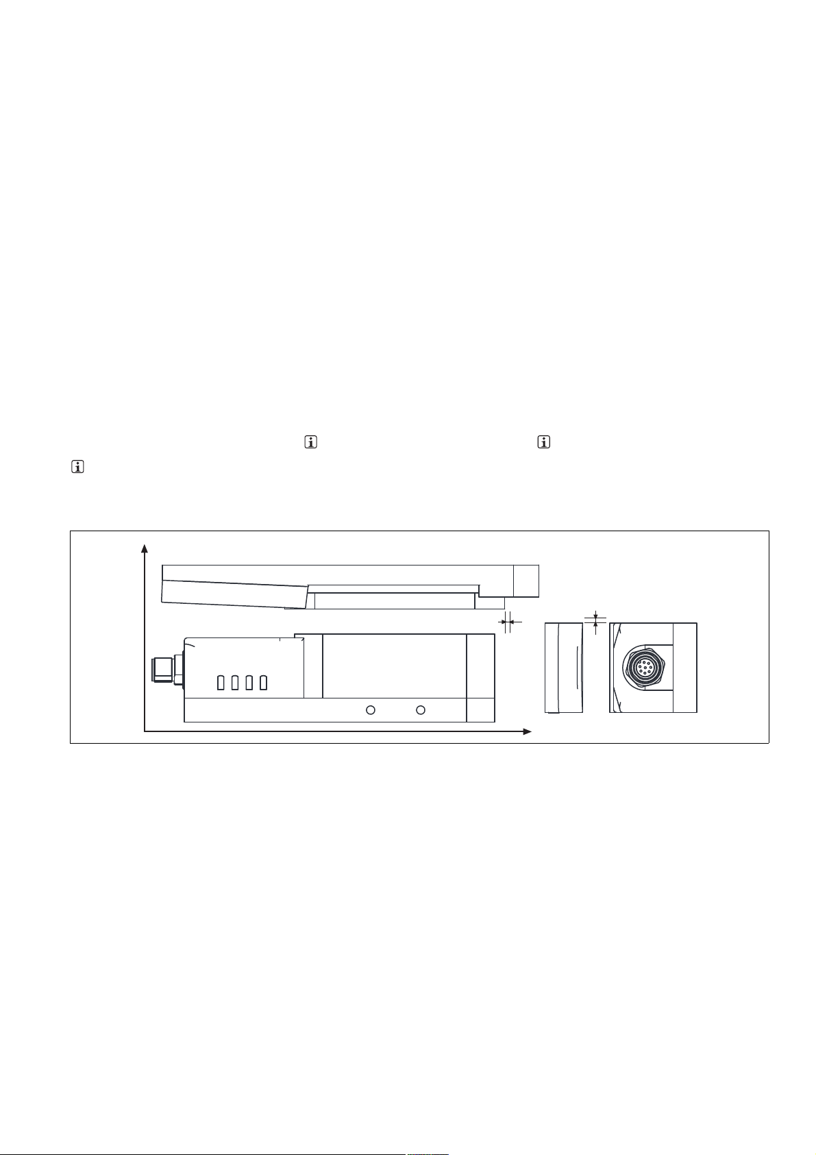
Abmessungen in mm Dimensions in mm Dimensions en mm
2
,
5
°
R25
M5 (6x)
24
93
R5
44
45
42
26
6
25
93
155
171
M12x1
R10
116
104
24
M5 (2x)
R33
22,5
16
52
188,46
173
188
14
5,3
10
7,5
Technische Daten Technical details Caractéristiques techniques
Elektrische Daten Electrical data Données électriques
Versorgungsspannung UBDC Supply voltage UB DC Tension d'alimentation UBDC 24 V
Spannungstoleranz Voltage tolerance Plage de la tension d'alimentation -15 %/+10 %
Leistungsaufnahme bei U
Max. Einschaltstromimpuls A1 Max. inrush current impulse A1 Impulsion de courant max. lors de
DC Power consumption at UB DC Consommation UBDC 7,2 W
B
9,90 A
la mise sous tension A1
Impulsdauer A1 Pulse duration A1 Durée d'impulsion A1 0,0020 ms
Spannung an Eingängen Voltage at inputs Tension sur entrées 24 V DC
Strom pro Eingang Current per input Courant par entrée 5,0 mA
Schaltstrom pro Ausgang Switching current per output Intensité de commutation par sortie 500 mA
Reststrom (I
Schaltleistung pro Ausgang Breaking capacity per output Puissance de commutation par sor-
Max. Schaltfrequenz Max. switch frequency Fréquence de commutation max. 1 Hz
Halbleiterausgänge (kurz-
schlussfest)
Sicherheitsausgänge OSSD OSSD safety outputs Sorties de sécurité OSSD 2
Meldeausgänge Signal outputs Sorties d'information 1
Max. Gesamtleitungswiderstand R
im Eingangskreis
max
) Residual current (Ir) Courant résiduel (Ir) 0,25 mA
r
Semiconductor outputs (short circuit proof)
Max. overall cable resistance R
l-
in the input circuit
tie
Sorties statiques (protégées contre
les courts-circuits)
Résistance max. de l'ensemble du
lmax
câblage R
trée
- 15 -
dans le circuit d'en-
lmax
12,0 W
1000 Ohm
Page 16

Elektrische Daten Electrical data Données électriques
Max. Leitungskapazität an den Sicherheitsausgängen
Leerlauf, PNOZ mit Relaiskontakten No-load, PNOZ with relay contacts Fonctionnement à vide, PNOZ avec
Max. line capacitance at the safety
outputs
Capacité max. du câblage sur les
sorties de sécurité
40 nF
contacts de relais
PNOZmulti, PNOZelog, PSS PNOZmulti, PNOZelog, PSS PNOZmulti, PNOZelog, PSS 70 nF
Zeiten Times Temporisations
Überbrückung bei Spannungseinbrüchen
Supply interruption before deenergisation
Tenue aux micro-coupures 17,0 ms
Einschaltverzögerung Switch-on delay Temps de montée
nach Anlegen von U
B
after applying U
B
après application de U
B
1,6 s
Eingänge typ. Input typ. Entrées env. 20 ms
Eingänge max. Input max. Entrées max. 35 ms
Betätiger typ. Actuator typ. Actionneur env. 500 ms
Rückfallverzögerung Delay-on de-energisation Temps de retombée
Eingänge typ. Input typ. Entrées env. 20 ms
Eingänge max. Input max. Entrées max. 35 ms
Betätiger typ. Actuator typ. Actionneur env. 25 ms
Betätiger max. Actuator max. Actionneur max. 260 ms
Testimpulsdauer Sicherheitsaus-
gänge
Test pulse duration on safety outputs
Durée du test impulsionnel pour les
sorties de sécurité
350 µs
Gleichzeitigkeit Kanal 1 und 2 Simultaneity, channel 1 and 2 Simultanéité des canaux 1 et 2 ∞
Umweltdaten Environmental data Données sur l'environnement
Temperatur Metallfläche Metal surface temperature Température de la surface métalli-
65 °C
que
EMV EMC CEM EN 55011: class A,
EN 61000-4-2, EN 61000-4-3,
EN 61000-4-4, EN 61000-4-6,
EN 61000-4-8
Schockbeanspruchung Shock stress Résistance aux chocs 30g , 11 ms
Schwingungen nach EN 60947-5-2 Vibration to EN 60947-5-2 Vibrations selon EN 60947-5-2
Frequenz Frequency Fréquence 10 - 55 Hz
Amplitude Amplitude Amplitude 1,00 mm
Verschmutzungsgrad Pollution degree Niveau d'encrassement 3
Bemessungsisolationsspannung Rated insulation voltage Tension assignée d'isolement 75 V
Bemessungsstoßspannungsfestig-
keit
Rated impulse withstand voltage Tension assignée de tenue aux
chocs
1,00 kV
Überspannungskategorie Overvoltage category Catégorie de surtensions III
Umgebungstemperatur Ambient temperature Température d'utilisation -25 - 55 °C
Lagertemperatur Storage temperature Température de stockage -25 - 70 °C
Mechanische Daten Mechanical data Données mécaniques
Magnethaltekraft ein Magnetic holding force on Force magnétique activée 1.000 N
Magnethaltekraft aus Magnetic holding force off Force magnétique désactivée 30 N
Höhenversatz max. Max. vertical offset Décalage en hauteur max. 5 mm
Seitenversatz max. Max. lateral offset Décalage latéral max. 3 mm
Winkelversatz max. Max. angular offset Décalage angulaire max. 2,5 deg
Hysterese typ. Hysteresis typ. Hystérésis env. 0,7 mm
Gesicherter Schaltabstand S
Gesicherter Ausschaltabstand S
Typischer Schaltabstand S
o
Min. Abstand zwischen Sicherheitsschaltern
Assured operating distance S
ao
Assured release distance S
ar
Typical switching distance S
Min. distance between safety
switches
Distance de commutation de sécu-
ao
rité S
ao
ar
Distance de déclenchement de sécurité S
ar
Distance de commutation caracté-
o
ristique S
o
Distance minimale entre les cap-
1,0 mm
8,0 mm
2,0 mm
30 mm
teurs de sécurité
Zugehörige Betätiger Corresponding actuator Actionneurs correspondants PSEN sl-1.0 1.1,
PSEN sl-1.0 2.1,
PSEN sl-1.0 VA
PSEN sl-1.0fm 1.1,
PSEN sl-1.0fm 2.1
Anschlussart Connection type Type de connection M12, 8-pol. Stiftstecker/
Connector male 8 pin M12/
Connecteur mâle M12 à 8 broches
Leitung Cable Câble LiYY 8 x 0,25 mm
2
Schutzart Protection type Indice de protection IP67
- 16 -
Page 17

Mechanische Daten Mechanical data Données mécaniques
Material Material Matériau
Gehäuse Housing Boîtier PBT
Ankerplatte Anchor plate Plaque de maintien Stahl vernickelt/nickel-plated
steel/acier nickelé
Bodenplatte Base plate Plaque support Anticorodal, hart eloxiert/Anti-
corodal, hard anodised/Anticorodal, anodisé dur No.
570600, 570601, 570602
Edelstahl 1.4301/Stainless
steel 1.4301/Acier fin 1.4301
No. 570630
Betätiger Actuator Actionneur Anticorodal, hart eloxiert/Anti-
corodal, hard anodised/Anticorodal, anodisé dur No.
570600, 570601, 570602
Edelstahl 1.4301/Stainless
steel 1.4301/Acier fin 1.4301
No. 570630
Abmessungen siehe Abbildung Dimensions, see graphic Dimensions, voir l'illustration
Gewicht Weight Poids
Sensor Sensor Capteur 1.148 g No. 570600, 570601,
570602
1.470 g No. 570630
Betätiger Actuator Actionneur 1.023 g No. 570630
599 g No. 570600, 570601,
570602
Sicherheitstechnische Kenndaten
PL nach EN ISO 13849-1: 2006 PL in accordance with EN ISO
Safety-related characteristic
data
Caractéristiques techniques de
sécurité
PL selon EN ISO 13849-1: 2006 PL e (Cat. 4)
13849-1: 2006
Kategorie nach EN 954-1 Category in accordance with EN
Catégorie selon EN 954-1 Cat. 4
954-1
SIL CL nach EN IEC 62061 SIL CL in accordance with EN IEC
SIL CL selon EN IEC 62061 SIL CL 3
62061
PFH nach EN IEC 62061 PFH in accordance with EN IEC
PFH selon EN IEC 62061 3,29E-09
62061
SIL nach IEC 61511 SIL in accordance with IEC 61511 SIL selon IEC 61511 SIL 3
PFD nach IEC 61511 PFD in accordance with IEC 61511 PFD selon IEC 61511 1,72E-04
T
[Jahr] nach EN ISO 13849-1:
M
2006
585241611
Es gelten die 2008-04 aktuellen Ausgaben der
TM [year] in accordance with EN
ISO 13849-1: 2006
The standards current on 2008-04 apply. Les versions actuelles 2008-04 des normes
TM [année] selon EN ISO 13849-1:
2006
s'appliquent.
20
Normen.
- 17 -
Page 18

Bestelldaten Order reference Références
Typ/Type/Type Stück/
Quantity/
Nombre
PSEN sl-1.0p 1.1 / PSEN sl-1.0 1 unit 1 Transpondertechnik/Trans-
PSEN sl-1.0p 2.1 / PSEN sl-1.0 1 unit 1 Transpondertechnik/ Trans-
PSEN sl-1.0p 2.2 / PSEN sl-1.0 1 unit 1 Transpondertechnik/ Trans-
PSEN sl-1.0p 1.1 VA/PSEN sl-1.0 1
1 Transpondertechnik/Trans-
unit
PSEN sl-1.0p 1.1 / PSEN sl-1.0fm 1
1 Transpondertechnik/Trans-
unit
PSEN sl-1.0p 2.1 / PSEN sl-1.0fm 1
1 Transpondertechnik/Trans-
unit
PSEN sl-1.0p 2.2 / PSEN sl-1.0fm 1
1 Transpondertechnik/Trans-
unit
PSEN sl bracket swing door 1 Montagewinkel für Schwenk- und
PSEN sl bracket sliding door 2 Montagewinkel für Schiebetüren/
Wirkweise/Operation/Actionnement
ponder technology/Technique
à transpondeur
ponder technology/Technique
à transpondeur
ponder technology/Technique
à transpondeur
ponder technology/Technique
à transpondeur
ponder technology/Technique
à transpondeur
ponder technology/Technique
à transpondeur
ponder technology/Technique
à transpondeur
Merkmale/Features/ Caractéristiques
Sicheres Schutztürsystem, codiert/
Safety gate system,coded/ Système
de sécurité pour protecteurs mobiles, codé
Sicheres Schutztürsystem, vollcodiert/Safety gate system, fully coded/ Système de sécurité pour
protecteurs mobiles, précodé
Sicheres Schutztürsystem, unikat
codiert/Safety gate system, uniquely
coded/ Système de sécurité pour
protecteurs mobiles, codé unique
Sicheres Schutztürsystem, codiert/
Safety gate system,coded/ Système
de sécurité pour protecteurs mobiles, codé
Sicheres Schutztürsystem, codiert
mit leichtgängigem Betätiger/
Safety gate system, coded with freemoving actuator/Système de sécurité pour protecteurs mobiles, codé
avec actionneur souple et flexible
Sicheres Schutztürsystem, vollcodiert mit leichtgängigem Betätiger/
Safety gate system, fully coded with
free-moving actuator/Système de
sécurité pour protecteurs mobiles,
codé multiple avec actionneur souple et flexible
Sicheres Schutztürsystem, unikat
codiert mit leichtgängigem Betätiger/
Safety gate system, uniquely coded
with free-moving actuator/Système
de sécurité pour protecteurs mobiles, codé unique avec actionneur
souple et flexible
Flügeltüren/Mounting bracket for
swing gates and folding gates/
Équerre de montage pour portes battantes et portes basculantes
Mounting bracket for sliding gates/
Équerre de montage pour portes
coulissantes
Bestell-Nr./Order
no./Référence
570 600
570 601
570 602
570 630
570 660
570 661
570 662
570 550
570 551
EG-Konformitätserklärung
1139424011
Diese(s) Produkt(e) erfüllen die Anforderungen
der Richtlinie 2006/42/EG über Maschinen des
europäischen Parlaments und des Rates. Die
vollständige EG-Konformitätserklärung finden
Sie im Internet unter www.pilz.com.
Bevollmächtigter: Norbert Fröhlich, Pilz GmbH
& Co. KG, Felix-Wankel-Str. 2, 73760 Ostfildern, Deutschland
21909-3FR-072013-11Printed in Germany
EC Declaration of Conformity
This (these) product(s) comply with the requirements of Directive 2006/42/EC of the European
Parliament and of the Council on machinery.
The complete EC Declaration of Conformity is
available on the Internet at www.pilz.com.
Authorised representative: Norbert Fröhlich,
Pilz GmbH & Co. KG, Felix-Wankel-Str. 2,
73760 Ostfildern, Germany
Déclaration de conformité CE
Ce(s) produit(s) satisfait (satisfont) aux exigences de la directive 2006/42/CE relative aux machines du Parlement Européen et du Conseil.
Vous trouverez la déclaration de conformité CE
complète sur notre site internet www.pilz.com.
Représentant : Norbert Fröhlich, Pilz GmbH &
Co. KG, Felix-Wankel-Str. 2, 73760 Ostfildern,
Allemagne
Originalbetriebsanleitung/Original instructions/Notice originale
21909-3FR-07, 2013-11 Printed in Germany
 Loading...