

Page 1
PSEN sg2c
Operating Manual 1003267-EN-04
} PSEN sensor technology
Page 2

Preface
This document is a translation of the original document.
All rights to this documentation are reserved by Pilz GmbH & Co. KG. Copies may be made
for internal purposes. Suggestions and comments for improving this documentation will be
gratefully received.
Source code from third-party manufacturers or open source software has been used for
some components. The relevant licence information is available on the Internet on the Pilz
homepage.
Pilz®, PIT®, PMI®, PNOZ®, Primo®, PSEN®, PSS®, PVIS®, SafetyBUS p®,
SafetyEYE®, SafetyNET p®, the spirit of safety® are registered and protected trademarks
of Pilz GmbH & Co. KG in some countries.
SD means Secure Digital
Page 3
Contents
Operating Manual PSEN sg2c
1003267-EN-04
3
Section 1 Introduction 5
1.1 Validity of documentation 5
1.2 Using the documentation 5
1.3 Definition of symbols 5
Section 2 Overview 7
2.1 Scope of PSEN sg2c Unit 7
2.2 Unit features 7
Section 3 Safety 8
3.1 Intended use 8
3.2 Safety regulations 8
3.2.1 Safety assessment 8
3.2.2 Use of qualified personnel 8
3.2.3 Warranty and liability 9
3.2.4 Disposal 9
3.3 For your safety 9
Section 4 Function description 10
4.1 Normal /Unlock mode 10
4.2 Escape release 11
4.3 Auxiliary release 13
4.4 Restart interlock 14
4.5 Holding forces 15
4.6 Pushbutton 16
4.7 Device types 17
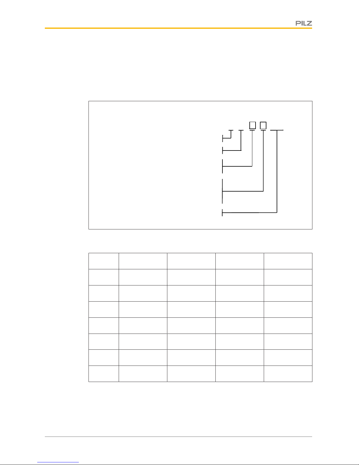
4.8 Block diagram 21
Section 5 Wiring 22
5.1 Notes on cable run 22
5.2 Recommended cable cross sections 23
5.3 General wiring guidelines 23
5.4 Terminal configuration 24
5.5 Wiring the connection terminals 25
5.6 E-STOP pushbutton connection 26
5.7 Enabling switch connection 26
5.8 EMC requirements 26
5.9 Connection to evaluation devices 27
5.9.1 Connection examples PNOZmulti 27
5.9.2 Connection examples PSS 27
5.10 Single connection 27
5.11 Series connection 28
Section 6 Installation 30
6.1 Initial installation of safety switch 31
6.2 Initial installation of handle unit 36
Page 4
Contents
Operating Manual PSEN sg2c
1003267-EN-04
4
6.3 Second installation of safety switch and handle unit / upgrade for lefthinged gates
37
6.4 Labelling the pushbuttons 37
6.5 Dimensions in mm 39
6.5.1 Drill holes 39
6.5.2 PSEN sg2c-3xxx 40
6.5.3 PSEN sg2c-5xxxxx 41
6.5.4 PSEN sg2c-5xxxxx-M12/5 42
Section 7 Adjustment 43
Section 8 Maintenance 44
Section 9 Operation 45
9.1 Status table 47
9.2 Toggle normal/unlock mode 48
9.3 Remedy 49
Section 10 Technical Details Order No. 570800-570804 51
Section 11 Technical Details Order No. 570806-570810 56
Section 12 Technical Details Order No. 570812-570816 60
Section 13 Technical Details Order No. 570818-570822 65
Section 14 Technical Details Order No. 570824-570828 69
Section 15 Technical Details Order No. 570830-570834 74
Section 16 Technical Details Order No. 570880-570884 78
Section 17 Safety characteristic data 82
Section 18 Order reference 83
18.1 Unit 83
18.2 Safety switch 84
18.3 Handle unit with actuator 85
18.4 Accessories 85
Section 19 Supplementary data 87
19.1 Radio approval 87
19.2 EC declaration of conformity 87
Page 5
Introduction
Operating Manual PSEN sg2c
1003267-EN-04
5
1 Introduction
1.1 Validity of documentation
This documentation is valid for the product PSEN sg2c. It is valid until new documentation
is published.
This operating manual explains the function and operation, describes the installation and
provides guidelines on how to connect the product.
1.2 Using the documentation
This document is intended for instruction. Only install and commission the product if you
have read and understood this document. The document should be retained for future reference.
1.3 Definition of symbols
Information that is particularly important is identified as follows:
DANGER!
This warning must be heeded! It warns of a hazardous situation that poses
an immediate threat of serious injury and death and indicates preventive
measures that can be taken.
WARNING!
This warning must be heeded! It warns of a hazardous situation that could
lead to serious injury and death and indicates preventive measures that can
be taken.
CAUTION!
This refers to a hazard that can lead to a less serious or minor injury plus
material damage, and also provides information on preventive measures
that can be taken.
NOTICE
This describes a situation in which the product or devices could be damaged and also provides information on preventive measures that can be
taken. It also highlights areas within the text that are of particular importance.
Page 6

Introduction
Operating Manual PSEN sg2c
1003267-EN-04
6
INFORMATION
This gives advice on applications and provides information on special features.
Page 7

Overview
Operating Manual PSEN sg2c
1003267-EN-04
7
2 Overview
2.1 Scope of PSEN sg2c Unit
} Safety switch
} Handle unit with actuator
} Colour covers for illuminated buttons
} Pin for escape release
2.2 Unit features
} Safe guard locking (only for revolving gates and swing gates)
} Safe interlocking (position monitoring)
} Transponder technology
} 2 safety inputs for series connection of multiple safety switches
} 2 safety outputs
} Guard locking element keeps the safety gate from being opened unintentionally
} Detection of broken bolt tongue and broken guard locking element
} Handle unit with locking lever to attach padlocks as a restart interlock
} Auxiliary release for opening the safety gate, when the plant's voltage is switched off
} Escape release for fast manual release of the guard locking in emergency situations
from within the danger zone (revolving gates and swing gates)
} Suitable for left and right hinged safety gates
Note: The handle unit PSEN sg2c actuator is only suitable for revolving gates and
swing gates.
} Plug-in spring-loaded terminals
} LED indicator for:
– Supply voltage/fault
– Gate locked
– State of the hazardous machine
– Request to stop the machine
– State of the inputs
– Bolt tongue engaged
} Depends on device type
– Various control elements, for example integral E-STOP pushbutton, section stop
pushbutton, key-operated pushbutton, key switch...
– Coding:
- coded
- uniquely coded
See section entitled Device types
Page 8

Safety
Operating Manual PSEN sg2c
1003267-EN-04
8
3 Safety
3.1 Intended use
The safety gate system is used for guard locking and interlocking swing gates and revolving
gates.
It meets the requirements in accordance with:
} EN 60947-5-3
} EN ISO 14119
} EN 62061: SIL CL 3
} EN ISO 13849-1: Up to PL e (Cat. 4)
The safety level PL e (Cat. 4)/SIL CL 3 can be achieved when
} The safety outputs use 2-channel processing and
} The solenoid is operated 2-channel via safe relay outputs, suitable for PL e (Cat. 4)/SIL
CL 3 applications.
Wiring errors should be excluded using appropriate measures. The potential solutions
are the protected cable layout or the use of pulsed semiconductor outputs.
3.2 Safety regulations
3.2.1 Safety assessment
Before using a unit it is necessary to perform a safety assessment in accordance with the
Machinery Directive.
Functional safety is guaranteed for the product as a single component. However, this does
not guarantee the functional safety of the overall plant/machine. In order to achieve the required safety level for the overall plant/machine, define the safety requirements for the
plant/machine and then define how these must be implemented from a technical and organisational standpoint.
3.2.2 Use of qualified personnel
The products may only be assembled, installed, programmed, commissioned, operated,
maintained and decommissioned by competent persons.
A competent person is someone who, because of their training, experience and current professional activity, has the specialist knowledge required to test, assess and operate the
work equipment, devices, systems, plant and machinery in accordance with the general
standards and guidelines for safety technology.
It is the company’s responsibility only to employ personnel who:
} Are familiar with the basic regulations concerning health and safety / accident preven-
tion
} Have read and understood the information provided in this description under "Safety"
} And have a good knowledge of the generic and specialist standards applicable to the
specific application.
Page 9
Safety
Operating Manual PSEN sg2c
1003267-EN-04
9
3.2.3 Warranty and liability
All claims to warranty and liability will be rendered invalid if
} The product was used contrary to the purpose for which it is intended
} Damage can be attributed to not having followed the guidelines in the manual
} Operating personnel are not suitably qualified
} Any type of modification has been made (e.g. exchanging components on the PCB
boards, soldering work etc.).
3.2.4 Disposal
} In safety-related applications, please comply with the mission time TM in the safety-re-
lated characteristic data.
} When decommissioning, please comply with local regulations regarding the disposal of
electronic devices (e.g. Electrical and Electronic Equipment Act).
3.3 For your safety
WARNING!
Potential loss of safety function during adjustment and repair work!
When carrying out adjustment and repair work, make sure that the power
supply of the plant is switched off and protected against switching on again.
WARNING!
Loss of safety function due to manipulative use of substitute actuating elements!
When substitute actuating elements are used, these have to be installed as
described in chapter Initial installation of safety switch [ 31]. When substitute actuating elements are used in a manipulative way to defeat the protective device, operating the plant presents a threat to life.
The operator has to consider this in the hazard analysis and he must determine possible countermeasures.
Page 10

Function description
Operating Manual PSEN sg2c
1003267-EN-04
10
4 Function description
The interlocking and guard locking system prevents the safety gates to the danger zone
from opening while the hazardous machine is switched on.
There is a high signal (safety gate closed and locked) at safety outputs X1-3 and X1-4 if the
following conditions are met simultaneously:
} Inputs X2-3 and X2-4 are high and
} The bolt tongue is within the response range and
} The guard locking element is engaged in the bolt tongue and
} The escape or auxiliary release pin is in the correct position.
Signal output X1-9 is high if:
} The bolt tongue is within the response rang
There is a low signal (safety gate open and hazardous machine function interlocked) at
safety outputs X1-3 and X1-4 if the following occurs:
} Inputs X2-3 or X2-4 are low or
} The guard locking element is outside the bolt tongue or
} The escape or auxiliary release has been operated or
} The guard locking element is not engaged in the bolt tongue.
If the safety outputs have been shut down by either of the inputs X2-3 or X2-4, they cannot
be switched back on until both inputs are low simultaneously.
To operate the solenoid, a high signal must be present at X1-6 (X2-6) and at X1-7 (X2-7)
after the hazardous movement has been ended.
4.1 Normal /Unlock mode
Normal mode:
The safety gate to the danger zone is not unlocked until the hazardous machine is stopped
and the pushbutton for access request has been operated.
} The guard locking element is disengaged from the bolt tongue as soon as there is a
high signal at terminals X1-6 and X1-7 or X2-6 and X2-7, followed by operation of the
pushbutton for access request.
Unlock mode:
The safety gate to the danger zone is unlocked when the hazardous machine is stopped.
This enables easier access for cleaning staff once the shift has ended, for example.
} The guard locking element is disengaged from the bolt tongue as soon as there is a
high signal at terminals X1-6 and X1-7 or X2-6 and X2-7.
Page 11
Function description
Operating Manual PSEN sg2c
1003267-EN-04
11
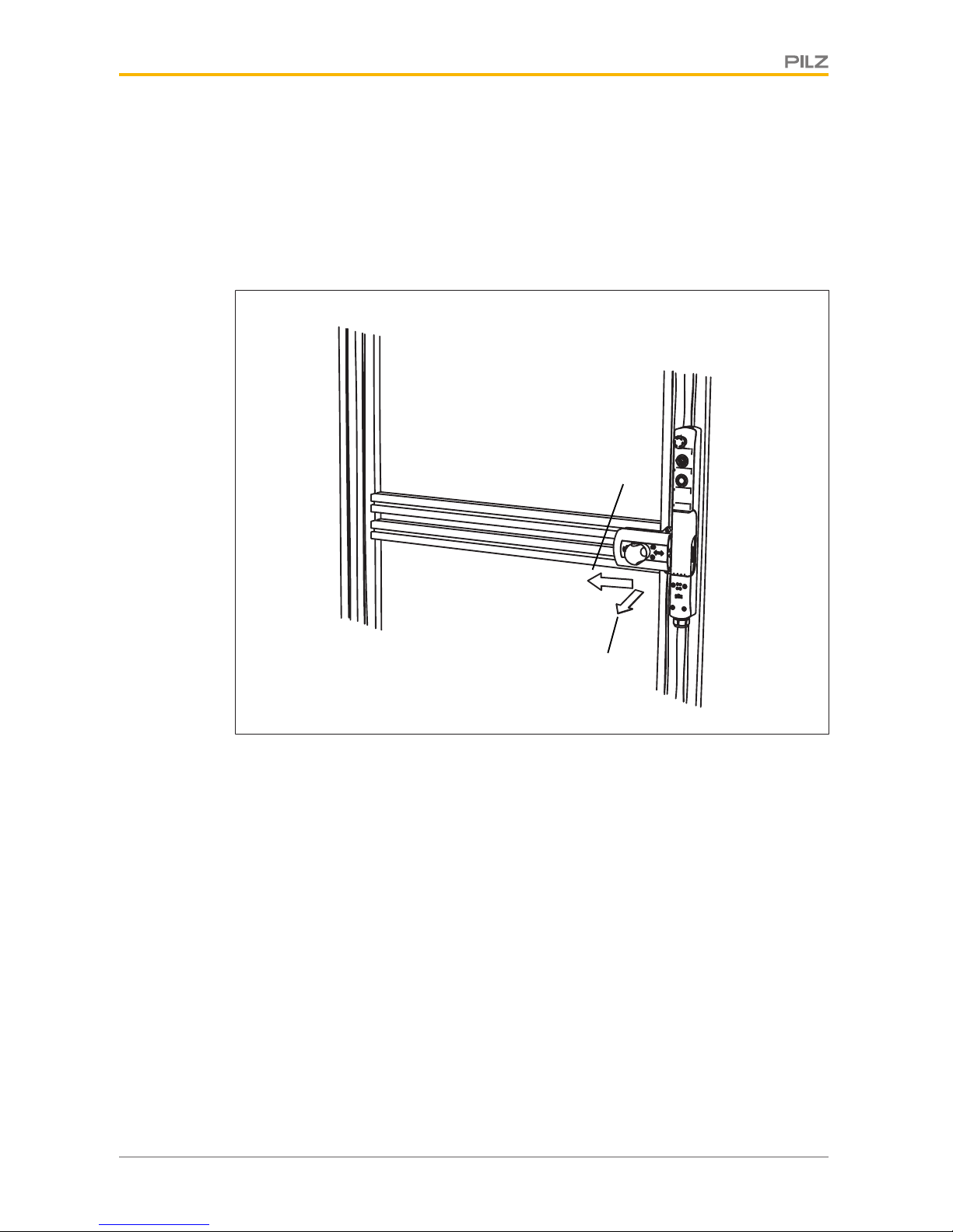
4.2 Escape release
The escape release enables the guard locking to be manually released from within the
danger zone.
[1]
[2]
[3]
[4]
[1]
[2]
Mode of operation
Within the danger zone, if the escape release pin [1] is pressed in the direction of the safety
gate, the cover on the escape release [2] detaches from the locked position and lifts upwards. The swivel piece [3] folds downwards. The bolt tongue [4] behind the swivel piece is
released. The safety gate can be opened immediately, enabling the operator to leave the
danger zone.
Page 12
Function description
Operating Manual PSEN sg2c
1003267-EN-04
12
WARNING!
Loss of safety function due to the incorrect installation of the escape release!
If the escape release pin is accessible from the outside, the guard locking
device can be released from the outside and the safety gates opened, although the hazardous machine is switched on.
Depending on the application, serious injury or death may result.
The escape release should be installed so that it is only accessible from inside the danger zone.
It is also important to refer to the maintenance instructions (see chapter entitled Maintenance [ 44])
INFORMATION
When the escape or auxiliary release is operated, there is a low signal at
the safety outputs X1-3 and X1-4. An error code is issued (see section entitled Remedy [ 49]). The PSENsgate is not ready for operation again
until the escape release or auxiliary release has been reset to its unoperated state and the error has been rectified and reset.
Please note that the cover of the escape release has to be checked and reinstalled after operation.
Page 13
Function description
Operating Manual PSEN sg2c
1003267-EN-04
13
4.3 Auxiliary release
When the plant is powered down, the auxiliary release enables the guard locking device to
be released from the access side to the danger zone.
[1]
[2]
[4]
[3]
Mode of operation:
Carefully remove the cover of the escape release (1) from the latch below. Use a screwdriver (2) to pull out the escape or auxiliary release pin (3) from the swivel piece (4). The
swivel piece folds downwards, the bolt tongue behind the swivel piece is released. The
safety gate to the danger zone can be opened.
INFORMATION
When the escape or auxiliary release is operated, there is a low signal at
the safety outputs X1-3 and X1-4. An error code is issued (see section entitled Remedy [ 49]). The PSENsgate is not ready for operation again
until the escape release or auxiliary release has been reset to its unoperated state and the error has been rectified and reset.
Please note that the cover of the escape release has to be checked and reinstalled after operation.
Page 14
Function description
Operating Manual PSEN sg2c
1003267-EN-04
14
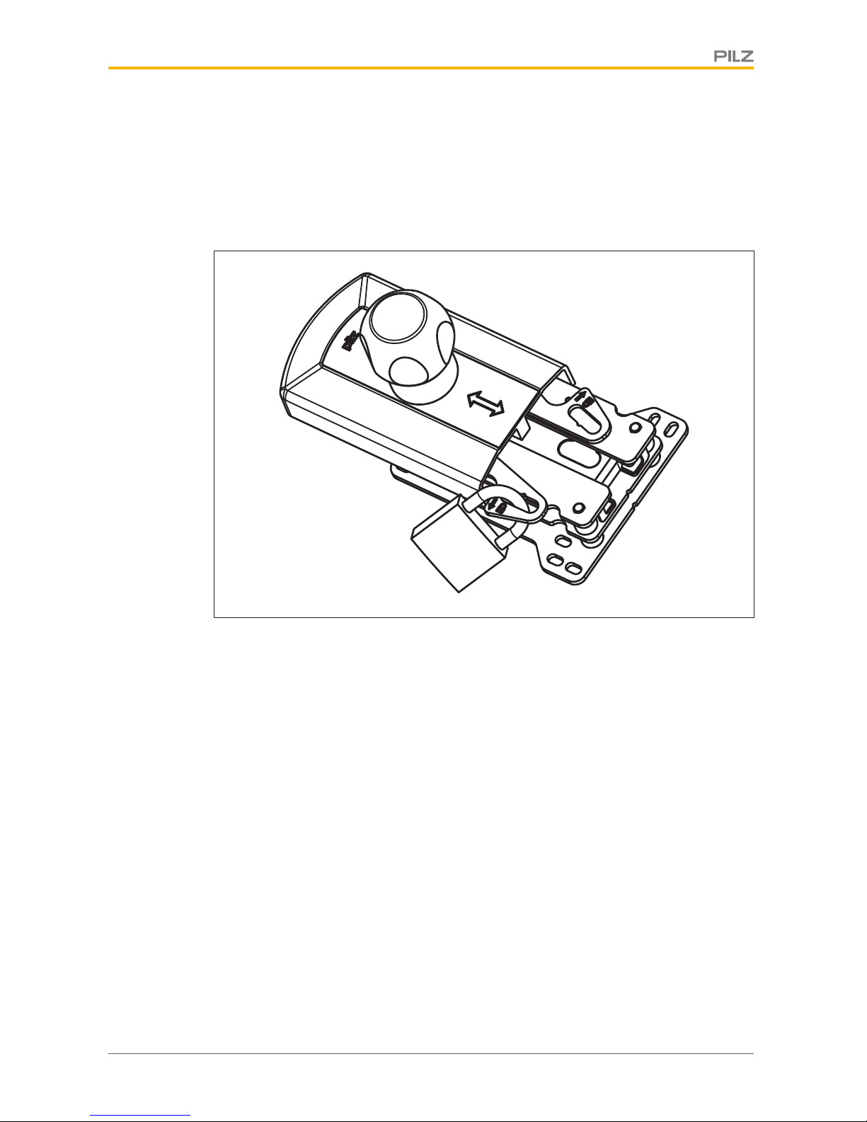
4.4 Restart interlock
To prevent the machine restarting while there is someone inside the danger zone, a padlock can be attached to one of the locking levers (see illustration). As a result, the guard
locking element cannot engage in the bolt tongue, the guard locking device is not activated
and the machine is prevented from restarting.
The padlock's shackle diameter may be max. 8 mm.
Page 15
Function description
Operating Manual PSEN sg2c
1003267-EN-04
15
4.5 Holding forces
The maximum holding forces that can be used to lock the safety gate are stated in the technical details.
A distinction is made between the following holding forces:
} Holding force in pan direction and
} Holding force in closing direction
Holding force in closing direction
Holding force in pan direction
Page 16
Function description
Operating Manual PSEN sg2c
1003267-EN-04
16
4.6 Pushbutton
Pushbutton 1
Pushbutton 2
Pushbutton 1
Pushbutton 2
Pushbutton 3
Pushbutton 4
PSEN sg2c-3... PSEN sg2c-5...
E-Stop/
Section stop
E-Stop/
Section stop
} Pushbutton 1: pushbutton for activating the safety gate guard locking device
By pressing the pushbutton for activating guard locking, the guard locking element is
engaged in the bolt tongue when the bolt tongue is detected by the sensor and a high
signal is present at X1-6 and X1-7 or at X2-6 and X2-7 (solenoid operation).
} Pushbutton 2: pushbutton for access request and release of the safety gate
– Pressing the pushbutton for access request disengages the guard locking element
from the bolt tongue when a high signal is present at X1-6 and X1-7 or at X2-6 and
X2-7 (solenoid operation).
– Pressing the pushbutton for access request switches output X1-5 (access request)
when a low signal is present at X1-6 and X1-7 or at X2-6 and X2-7 (solenoid operation).
Depending on the design, the device also has:
} E-STOP / or section stop pushbutton
} Pushbutton 3 and pushbutton 4
Pushbuttons that can be used depending on the application:
– Operating a pushbutton switches the pushbutton output
– The LEDs of the pushbuttons can be operated via the LED inputs.
Further information on the different types can be found in the section entitled Device
types [ 17].
Page 17
Function description
Operating Manual PSEN sg2c
1003267-EN-04
17
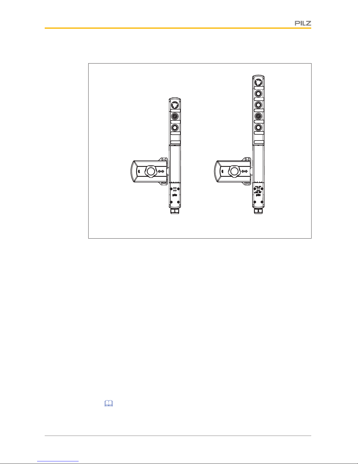
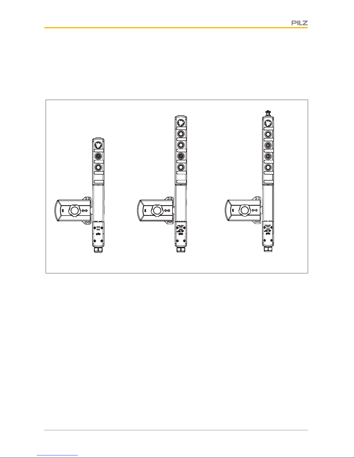
4.7 Device types
21 different versions are available. They differ as follows:
} Number and quality of the pushbuttons
} Coded or uniquely coded
} With or without M12 connection for enabling switch
PSEN sg2c-3xxx PSEN sg2c-5xxxxx
PSEN sg2c-5xxxxx-M12/5
[1]
[2]
[3]
[1]
[2]
[3]
[4]
[5]
[1]
[2]
[3]
[4]
[5]
[6]
Page 18
Function description
Operating Manual PSEN sg2c
1003267-EN-04
18
PSEN sg2c-3xxx (3 pushbuttons)
[1] Pushbutton 1: pushbutton for activating the safety gate guard locking device
[2] Pushbutton 2: pushbutton for access request and release of the safety gate
[3] E-STOP / or section stop pushbutton
Type code:
PSEN sg2c - 3 L X X 2.2*
3 pushbuttons = 3
Pushbutton illuminated = L
Pushbutton unilluminated = P
Key switch = B
E-STOP pushbutton = E
Section stop pushbutton = S
No pushbutton = C
uniquely coded
[1] [2] [3]
*not included with all versions
Types:
Pushbutton 1 Pushbutton 2 E-Stop/
Section stop
Coding
-3LPE Pushbutton
illuminated
Pushbutton
unilluminated
E-Stop coded
-3LBE Pushbutton
illuminated
Key
switch
E-Stop coded
-3LPS Pushbutton
illuminated
Pushbutton
unilluminated
Section
stop
coded
-3LBS Pushbutton
illuminated
Key-operated
pushbutton
Section
stop
coded
-3LPC Pushbutton
illuminated
Pushbutton
unilluminated
--- coded
-3LBC Pushbutton
illuminated
Key-operated
pushbutton
--- coded
-3LPE 2.2 Pushbutton
illuminated
Pushbutton
unilluminated
E-Stop uniquely coded
Page 19
Function description
Operating Manual PSEN sg2c
1003267-EN-04
19
PSEN sg2c-5-xxxxx and PSEN sg2c-5-xxxxx-M12 (5 pushbuttons):
[1] Pushbutton 1: pushbutton for activating the safety gate guard locking device
[2] Pushbutton 2: pushbutton for access request and release of the safety gate
[3], [4] pushbuttons 3 - 4: can be used depending on the application
[5] E-STOP / or section stop pushbutton
[6] M12 connection for enabling switch
Type code:
PSEN sg2c - 5 L X X L X - M12/5* 2.2*
5 pushbuttons = 5
Enabling switch
Pushbutton illuminated = L
Pushbutton unilluminated = P
Key switch = B
E-STOP pushbutton = E
Section stop pushbutton = S
No pushbutton = C
uniquely coded
Pushbutton illuminated = L
Key switch = B
Pushbutton illuminated = L
[1] [2] [3] [4] [5] [6]
Fig.: *not included with all versions
Types:
Pushbut-
ton 1
Pushbut-
ton 2
Pushbut-
ton 3
Pushbut-
ton 4
E-Stop/
Section
stop
M12Coding
-5LPLLE Pushbut-
ton
illuminated
Pushbut-
ton
unillumin-
ated
Pushbut-
ton
illuminated
Pushbut-
ton
illuminated
E-Stop --- coded
-5LBLLE Pushbut-
ton
illuminated
Key-oper-
ated
pushbutton
Pushbut-
ton
illuminated
Pushbut-
ton
illuminated
E-Stop --- coded
-5LPLLS Pushbut-
ton
illuminated
Pushbut-
ton
unillumin-
ated
Pushbut-
ton
illuminated
Pushbut-
ton
illuminated
Section
stop
--- coded
Page 20
Function description
Operating Manual PSEN sg2c
1003267-EN-04
20
-5LBLLS Pushbut-
ton
illuminated
Key-oper-
ated
pushbutton
Pushbut-
ton
illuminated
Pushbut-
ton
illuminated
Section
stop
--- coded
-5LPLLC Pushbut-
ton
illuminated
Pushbut-
ton
unillumin-
ated
Pushbut-
ton
illuminated
Pushbut-
ton
illuminated
--- --- coded
-5LBLLC Pushbut-
ton
illuminated
Key-oper-
ated
pushbutton
Pushbut-
ton
illuminated
Pushbut-
ton
illuminated
--- --- coded
-5LPKLEM12/5
Pushbut-
ton
illuminated
Pushbut-
ton
unillumin-
ated
Key
switch
Pushbut-
ton
illuminated
E-Stop Yes coded
-5LBKLEM12/5
Pushbut-
ton
illuminated
Key-oper-
ated
pushbutton
Key
switch
Pushbut-
ton
illuminated
E-Stop Yes coded
-5LPKLSM12/5
Pushbut-
ton
illuminated
Pushbut-
ton
unillumin-
ated
Key
switch
Pushbut-
ton
illuminated
Section
stop
Yes coded
-5LBKLSM12/5
Pushbut-
ton
illuminated
Key-oper-
ated
pushbutton
Key
switch
Pushbut-
ton
illuminated
Section
stop
Yes coded
-5LPKLCM12/5
Pushbut-
ton
illuminated
Pushbut-
ton
unillumin-
ated
Key
switch
Pushbut-
ton
illuminated
--- --- coded
-5LBKLCM12/5
Pushbut-
ton
illuminated
Key-oper-
ated
pushbutton
Key
switch
Pushbut-
ton
illuminated
--- Yes coded
-5LPLLE
2.2
Pushbut-
ton
illuminated
Pushbut-
ton
unillumin-
ated
Pushbut-
ton
illuminated
Pushbut-
ton
illuminated
E-Stop --- uniquely
coded
-5LPKLEM12/5 2.2
Pushbut-
ton
illuminated
Pushbut-
ton
unillumin-
ated
Key
switch
Pushbut-
ton
illuminated
E-Stop Yes uniquely
coded
Page 21
Function description
Operating Manual PSEN sg2c
1003267-EN-04
21
4.8 Block diagram
6
3
24 V
Escape
Release Pin
24 V
(Connector)
Fig.: The connections shown in blue are available depending on the device type (see section entitled Device
types [ 17]).
Page 22
Wiring
Operating Manual PSEN sg2c
1003267-EN-04
22
5 Wiring
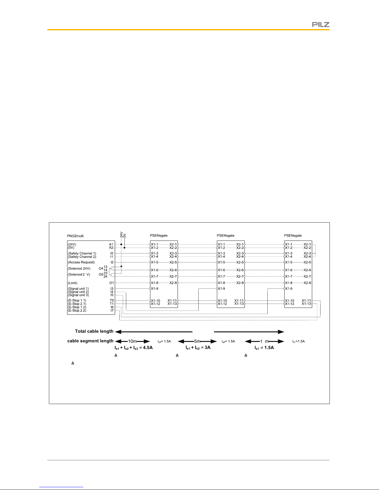
5.1 Notes on cable run
The maximum cable run depends on the voltage drop in the supply voltage conductors for
solenoid operation. The level of voltage drop is determined by the
} cable resistance of the cables
} solenoid current of the solenoid
If the voltage drop in the supply voltage conductors becomes too high, the voltage for
solenoid operation can permanently be set to the upper tolerance range (see Technical details).
The max. cable diameter is 10 mm.
Example:
} Connecting 3 safety switches in series
} Total cable run: 25 m
} Conductor cross section: 0.5 mm
2
} Solenoid current per solenoid: 1.5 A
} Voltage for solenoid operation: 24 V
4
U~0.05*10*1.5*4.5~3.4 V U~0.05*5*1.5*3~1.1 V U~0.05*10*1.5*1.5~1.5 V
U~cable specific impedence*cable length*cable factor*current
Cable impedence(2x0.25 mm²)
=0.05 Ohm/meter
25 m
0
The voltage drop over all the safety switches is 6 V. This means, there are only 18.0 V at
the terminals of the last solenoid. The solenoid is no longer operated reliably. If the voltage
for operating the solenoid is increased by the max. permitted tolerance to 26.4, there are
still 20.4 V at the terminals of the last solenoid. The solenoid switches reliably.
Page 23
Wiring
Operating Manual PSEN sg2c
1003267-EN-04
23
5.2 Recommended cable cross sections
The values in the table are valid for a series connection with max. 3 sensors and a voltage
for solenoid operation of 24 V. The solenoid current is 1.5 A per solenoid.
For differing values the conductor cross section must be calculated.
Total cable run [m]
1 safety switches 2 safety switches 3 safety switches
5 0.25 mm2, AWG24 0.25 mm2, AWG24 0.5 mm2, AWG21
10 0.25 mm2, AWG24 0.25 mm2, AWG24 0.5 mm2, AWG21
15 0.25 mm2, AWG24 0.25 mm2, AWG24 0.5 mm2, AWG21
20 0.25 mm2, AWG24 0.5 mm2, AWG21 x
25 0.25 mm2, AWG24 0.5 mm2, AWG21 x
30 0.25 mm2, AWG24 x x
40 0.5 mm2, AWG21 x x
50 0.5 mm2, AWG21 x x
60 0.5 mm2, AWG21 x x
70 x x x
Cable runs marked with an x are not recommended.
For operating several safety switches with greater cable runs, the cables for solenoid operation (terminals X1-6 and X1-7) have to be carried individually, or several cables have to be
used. If more than three safety switches are connected in series or cable runs over 60 m
are required, please contact Pilz.
The permitted conductor cross section is at least 0.25 mm². To have a higher conductor
cross section, two cable cores can be inserted into a terminal. This adds together the conductor cross sections and halves the cable resistances. In this case, use a terminal lug! The
signals important for cable resistance are:
} 24 V (X1-1 or X2-1)
} 0 V (X1-2 or X2-2)
} the two solenoid operation signals (X1-6 and X1-7 or X2-6 and X2-7).
5.3 General wiring guidelines
Please note:
} All metallic surfaces on the safety switch are connected to 0 V via a resistor (100
kOhm) for functional earthing.
} UL requirements:
– Use copper wiring with a temperature stability of 75 °C.
– Use an LVLC supply (LVLC: limited voltage, limited current).
– Use multicore cable with a cable diameter of 6 ... 10 mm.
} When 2 cables are used, make sure that both cables have the same cable diameter,
otherwise the strain relief will fail.
Page 24
Wiring
Operating Manual PSEN sg2c
1003267-EN-04
24
} The permitted conductor cross section for the connectors is 0.25 - 1.0 mm², 23 - 17
AWG.
} When calculating the max. cable run, remember to take into account the chapter "Notes
on cable run".
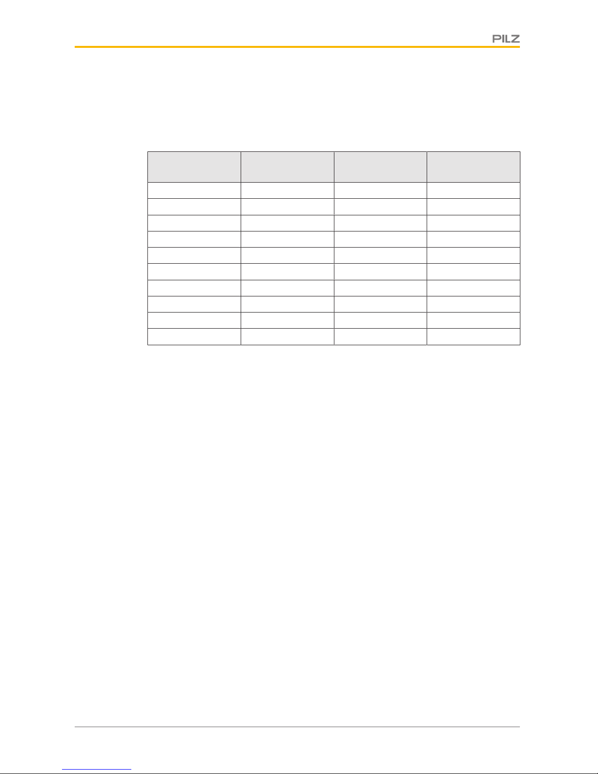
5.4 Terminal configuration
1
X2
3
5
7
9 11 13 15
246 8 10 12 14 16
1
X1
3
5
7
9 11 13 15
246 8 10 12 14 16
Terminal PSEN sg2c-3xxx PSEN sg2c-5xxxx
PSEN sg2c-5xxxxM12/5
X1-1 - X2-1
linked internally
+24 VDC supply voltage +24 VDC supply voltage +24 VDC supply voltage
X1-2 - X2-2
linked internally
0 V 0 V 0 V
X1-3 Safety output channel 1
(OSSD1)
Safety output channel 1
(OSSD1)
Safety output channel 1
(OSSD1)
X1-4 Safety output channel 2
(OSSD2)
Safety output channel 2
(OSSD2)
Safety output channel 2
(OSSD2)
X1-5 - X2-5
linked internally
Output pushbutton for access request [2]
Output pushbutton for access request [2]
Output pushbutton for access request [2]
X1-6 - X2-6
linked internally
Solenoid operation (24 V) Solenoid operation (24 V) Solenoid operation (24 V)
X1-7 - X2-7
linked internally
Solenoid operation (24 V) Solenoid operation (24 V) Solenoid operation (24 V)
X1-8 - X2-8
linked internally
Input for activating the
safety gate guard locking
device
Input for activating the
safety gate guard locking
device
Input for activating the
safety gate guard locking
device
X1-9 Signal output for state of
the bolt tongue
Signal output for state of
the bolt tongue
Signal output for state of
the bolt tongue
X1-10 E-STOP 1.1 E-STOP 1.1 E-STOP 1.1
X1-11 E-STOP 1.2 E-STOP 1.2 E-STOP 1.2
X1-12 E-STOP 2.1 E-STOP 2.1 E-STOP 2.1
X1-13 E-STOP 2.2 E-STOP 2.2 E-STOP 2.2
Page 25
Wiring
Operating Manual PSEN sg2c
1003267-EN-04
25
Terminal PSEN sg2c-3xxx PSEN sg2c-5xxxx
PSEN sg2c-5xxxxM12/5
X1-14 n.c Pushbutton 3 LED3 n.c
X1-15 n.c Pushbutton 4 LED4 Pushbutton 4 LED4
X1-16 Signal output, E-STOP Signal output, E-STOP Enabling switch Pin5 and
signal output E-STOP
X2-3 Input, channel 1 Input, channel 1 Input, channel 1
X2-4 Input, channel 2 Input, channel 2 Input, channel 2
X2-9 n.c n.c Enabling switch M12 Pin
1 (optional)
X2-10 n.c n.c Enabling switch M12 Pin
2 (optional)
X2-11 n.c n.c Enabling switch M12 Pin
3 (optional)
X2-12 n.c n.c Enabling switch M12 Pin
4 (optional)
X2-13 n.c Pushbutton 3 channel 1 Pushbutton 3: Key switch
rotated 90° to the left
X2-14 n.c n.c Pushbutton 3: Key switch
rotated 90° to the right
X2-15 n.c Pushbutton 4 channel 1 Pushbutton 4 channel 1
X2-16 n.c n.c n.c
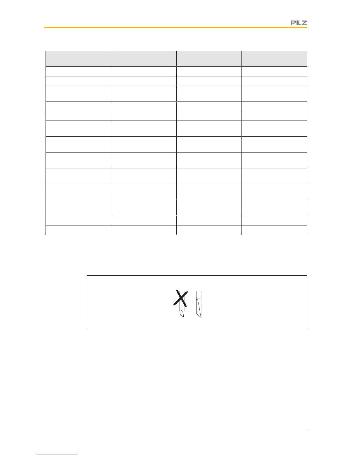
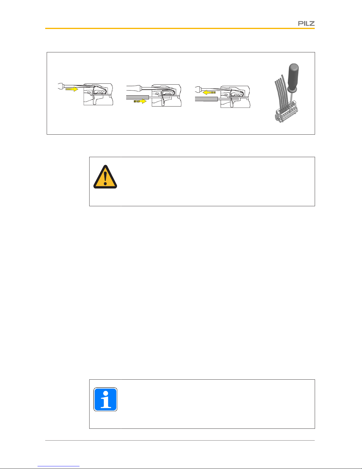
5.5 Wiring the connection terminals
Connecting the cables:
} Use a flat blade screwdriver (DIN 5264-A)!
DIN 5264-A
} Strip the wire back 7 mm.
} Insert the screwdriver into the square hole.
} Insert the stripped wire into the square hole as far as it will go.
} Pull out the screwdriver.
} Check that the cable is firmly seated.
Page 26
Wiring
Operating Manual PSEN sg2c
1003267-EN-04
26
5.6 E-STOP pushbutton connection
CAUTION!
With versions with integral E-STOP pushbutton, the E-STOP pushbutton
(terminals X1-10 to X1-13) must be integrated into the plant/machine's ESTOP concept in accordance with EN/IEC 60204.
5.7 Enabling switch connection
Details of the pin assignment of the female 5-pin M12 connector for the enabling switch can
be found in the block diagram and the terminal configuration.
We recommend you use the PIT en1.0p-5m-s (order no. 401 110) as the enabling switch.
5.8 EMC requirements
Please note:
} The power supply must meet the regulations for extra low voltages with protective sep-
aration (SELV, PELV).
} The inputs and outputs of the safety switch must have a protective separation to
voltages over 60 V AC.
} The supply voltage has to be at the safety switch terminals within the indicated toler-
ances (see Technical details).
} the supply voltage of the safety switch must be secured with a fuse of type quick
between 2 A and 10 A.
} The electrical installation must be performed in accordance with IEC/EN 60204.
} The assured release distance (SaO) can be influenced by external influences (e.g.: tem-
perature, dirt, EMC) (see Technical details).
INFORMATION
Safety relays with a wide-range power supply or in AC device versions have
internal potential isolation and are not suitable as evaluation devices. Only
safety relays with a 24 VDC supply voltage are suitable.
Page 27
Wiring
Operating Manual PSEN sg2c
1003267-EN-04
27
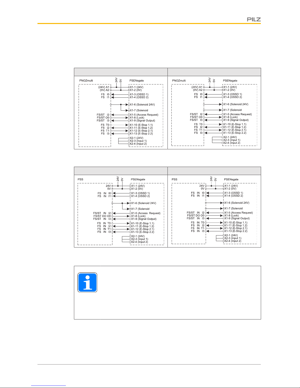
5.9 Connection to evaluation devices
5.9.1 Connection examples PNOZmulti
up to PL d/SIL CL 2 PL e/SIL CL 3
24 V)
FS O1
24 V)
FS O1
FS O2
5.9.2 Connection examples PSS
up to PL d/SIL CL 2 PL e/SIL CL 3
24 V)
FS DO O1
24V)
FS DO O1
FS DO O2
5.10 Single connection
INFORMATION
When the solenoid is operated in single-channel, only a safety level of PL d
(Cat.2)/SILCL2 can be achieved.
To achieve PLe(Cat.4/SILCL3, the solenoid must have dual-channel operation, e. g. via safe pulsed semiconductor outputs with high current load
capacity (0.9 A for 50 ms).
Page 28

Wiring
Operating Manual PSEN sg2c
1003267-EN-04
28
X2-4
24 V
0 V
I1 (ST)
I3 (FS)
A1
A2
PSENsgate
O1 (FS)
Auswertegerät/
Evaluation device/
Appareil de surveillance/
Dispositivo di controllo
FS: Fail-safe
ST: Standard
I4 (FS)
X2-3
X1-3 X1-4
X1-1
X1-2
X1-6 X1-5
I2 (ST)
X1-9
O3 (ST)
X1-8
O2 (FS)
X1-7
5.11 Series connection
CAUTION!
Extension of delay-on de-energisation
When several (n) devices are connected in series, the delay-on de-energisation time adds with the number of interconnected safety switches.
The may. delay-on de-energisation is composed of
max. delay-on de-energisation actuator
+ (n-1) x max. delay-on de-energisation of the inputs
+ delay-on de-energisation of the evaluation device
INFORMATION
When the solenoid is operated in single-channel, only a safety level of PL d
(Cat.2) / SILCL2 can be achieved.
To achieve PLe(Cat.4)/SILCL3, the solenoid must have dual-channel operation.
For applications with single-channel operation of the solenoid (up to PL d/SIL CL 2) a momentarily overloadable safe output (1.8 A for 50 ms) can be used.
Page 29

Wiring
Operating Manual PSEN sg2c
1003267-EN-04
29
The device can be switched in series with all safety switches from Pilz. In the connection
example, the safety switch guard locking device is activated / deactivated via access request (X1-5). The maximum switching current of the solenoid is present only while switching the solenoids for about 50 ms. The solenoids of the safety switches are switched with a
low time offset of ca. 1 s, to avoid power surges at the evaluation device.
X2-3
24 V
A1
A2
PLC
PSENsgate
I1 (FS)
I2 (FS)
FS: Fail-safe
ST: Standard
PSENsgate
PSENsgate
Auswertegerät/
Evaluation device/
Appareil de surveillance/
Dispositivo di controllo
I1 (ST)
X2-3
X2-4
X1-3 X1-4
X1-9
X2-3
X2-4
X1-1
X1-1
X1-2
X1-2
X2-1
X2-2
X1-6
X2-6
X1-6
X2-6
X1-7
I2 (ST)
X1-9
I3 (ST)
X1-9
X1-2
X2-2
X2-7
I4 (ST)
X1-5
X2-7
X1-7
X1-7
X1-1
X2-1
X1-3
X1-4
X2-4
X1-3
X1-4
X2-5
X1-5
X2-5
X1-5
0 V
O1 (FS)
X1-6
O2 (FS)
X2-8
X1-8
X2-8
X1-8
O3 (ST)
X1-8
Page 30

Installation
Operating Manual PSEN sg2c
1003267-EN-04
30
6 Installation
} When installing make sure you comply with the requirements of EN ISO 14119.
} The safety switch and handle unit with actuator should be installed opposite each other
in parallel.
} The safety switch and handle unit with actuator should be secured only with socket
head cap screws M5 - DIN EN ISO 4762.
NOTICE
It must not be possible to operate or remove the handle unit from inside the
danger zone. Protect the handle unit from access, e.g. by covers on the
hazard side of the door.
INFORMATION
The handle unit should be protected from unauthorised removal and from
contamination.
CAUTION!
Safety switch and handle unit
– Should not be exposed to heavy shock or vibration
– Should not be used as a limit stop
Page 31

Installation
Operating Manual PSEN sg2c
1003267-EN-04
31
6.1 Initial installation of safety switch
} Open the cover for the escape release in the direction of opening and remove it.
} Prepare 9 mm hole for the escape release and attach profile nuts to the aluminium pro-
file (see also Dimensions for the drill holes [ 39]).
The escape release does not require a drill hole.
Page 32

Installation
Operating Manual PSEN sg2c
1003267-EN-04
32
} Align actuator guide plate and safety switch. Please note the distance between the
handle unit and the safety switch (see chapter entitled Adjustment [ 43]).
} Fix actuator guide plate and safety switch with M5 - DIN EN ISO 4762 - socket head
cap screws (hexagon socket, e.g.: Bossard: BN3 (without shaft), galvanised blue,
torque setting Ma = 5 Nm). Use washer M5 - DIN125A (e.g.: Bossard: BN 715, galvanised blue, dimension: 10 x 5.3 x 1) for this.
The fixing screws on the safety switch are located under the cover of the escape release. Use an appropriate screw adhesive (e.g. Loctite 2700) to protect the socket head
cap screws from working loose.
WARNING!
Risk of manipulation of the safety device if the actuator guide plate is not
secured permanently!
If the actuator guide plate is not secured permanently, there is a risk that the
safety function will be defeated through manipulation. Depending on the application, serious injury or death may result.
– If the actuator guide plate is installed using only the unprotected
screws [1] accessible from the side, then one-way screws must be
used for manipulation protection.
– If the screws used under the bolt tongue [2] are protected against
manipulation, then this is not necessary.
[1]
[2]
Page 33

Installation
Operating Manual PSEN sg2c
1003267-EN-04
33
} Unscrew the pressure screw [1] from the housing and remove the rubber seal [2].
} Thread the cable through the correctly oriented pressure screw and the rubber seal, re-
move the blind insert if necessary.
} Remove the countersunk screws [3] on the housing cover for the connection terminals
and slowly remove the housing cover [4]. In doing so, the spring mechanism moves the
cover of the escape release upwards.
} Unscrew the strain relief plate [5].
} Connect and insert connection terminals.
} Position cable and screw on the strain relief plate (torque setting Ma 0.9 Nm +/- 0.1 (8
in-lbs)).
} Fix housing cover with screws (torque setting Ma 1.7 Nm +/- 0.1 (15 in-lbs)).
} Move the rubber seal along the cables and position it in the housing.
} Screw pressure screw on the thread.
[1]
[2]
[3]
[4]
[5]
Page 34

Installation
Operating Manual PSEN sg2c
1003267-EN-04
34
} Insert the escape or auxiliary release pin [1] into the safety switch and push it right to
the back. The swivel piece [2] must be maintained in a vertical position, safe from the
escape or auxiliary release pin. Screw the ball head on to the escape release pin.
Check the escape release for ease of movement. Fold down the cover on the escape
release ② and lock into position.
} Screw the ball handle [4] into the handle unit, lock the bolt tongue of the handle unit [5]
into position in the actuator guide plate. (See section entitled Initial installation of handle
unit [ 36]
INFORMATION
If the escape or auxiliary release pin is not inserted into the swivel piece
correctly, commissioning of the PSENsgate will be aborted and an error
code will be issued.
[2]
[3]
[4]
[5]
[1]
Page 35

Installation
Operating Manual PSEN sg2c
1003267-EN-04
35
WARNING!
Loss of safety function due to the incorrect installation of the escape release!
If the escape release pin is accessible from the outside, the guard locking
device can be released from the outside and the safety gates opened, although the hazardous machine is switched on.
Depending on the application, serious injury or death may result.
The escape release should be installed so that it is only accessible from inside the danger zone.
It is also important to refer to the maintenance instructions (see chapter entitled Maintenance [ 44])
Shorten the escape release pin
The escape release pin can be shortened, if required, so that it does not extend too much
into the danger zone.
NOTICE
Inside the danger zone, the escape release pin must protrude at least 65
mm from the profile. After installation, the escape release must be checked
for proper operation. When shortening the escape release pin, the material
of the escape release must not exceed a temperature of 100°C
65 mm
45 mm
Pin for escape release
with ball handle
Pin for auxiliary release
If the escape release is not to be used, the escape release pin can be shortened to a length
of 45 mm and then be used for the auxiliary release. The auxiliary release pin is also available as an accessory (see order references for Accessories [ 85]).
NOTICE
Please note that the escape release pin must not be shorter than 45 mm, to
guarantee the full holding force.
Page 36

Installation
Operating Manual PSEN sg2c
1003267-EN-04
36
6.2 Initial installation of handle unit
} Check whether the present bolt tongue is correctly oriented at the handle unit. Standard
is right-hand door hinge at delivery (leave of the door opens to the right).
} Coat the thread of the ball handle with screw adhesive (e.g. Loctite 2700) and screw
firmly together with the handle unit by hand.
Install bolt tongue with handle unit:
} Remove the screw blocking the spring-loaded limit stop mechanism (see illustration
"Handle unit and actuator with screw").
} Position the screwdrivers in the slots provided on the limit stop mechanism (see illustra-
tion "Unlock bolt").
} Press screwdriver towards the base plate to release the spring-loaded limit stop mech-
anism.
} Engage bolt tongue with handle unit in the actuator guide.
} Ensure by moving backwards and forwards towards the limit stop that the handle unit
cannot be removed from the actuator guide.
} Re-attach the screw with a torque setting of 2 Nm +/-0.1. Use an appropriate screw ad-
hesive (e.g. Loctite 2700) to protect the screw from working loose.
Fig.: Handle unit and actuator with screw
Page 37

Installation
Operating Manual PSEN sg2c
1003267-EN-04
37
Fig.: Unlock bolt
6.3 Second installation of safety switch and handle unit /
upgrade for left-hinged gates
} Remove the screw blocking the spring-loaded limit stop mechanism (see illustration in
previous section "Handle unit and actuator with screw").
} Uninstall the safety switch from the installation site (compare steps in section en-
titledInitial installation of safety switch [ 31] in reverse order).
} Uninstall handle unit from the gate. To do this, position the screwdrivers in the slots
provided on the limit stop mechanism (see graphic "Unlock bolt").
} Press screwdriver towards the base plate to release the spring-loaded limit stop mech-
anism.
} Disengage bolt tongue with handle unit in the actuator guide.
} Remove exposed fixing screws.
} Unscrew ball handle from the handle unit.
} Remove the cover of the handle unit from the bolt tongue (2 countersunk screws).
} Take limit stop from the bolt tongue and insert it from the other side into the location
hole.
} Turn bolt tongue around its longitudinal axis and screw together with the cover of the
handle unit.
} Carry out the steps from the sections entitled Initial installation of handle unit [ 36]
and Initial installation of safety switch [ 31].
6.4 Labelling the pushbuttons
Colour covers are supplied with the PSEN sg2c Unit; these must be attached to the pushbuttons, based on their function (see also order references for Accessories [ 85]).
} Press the colour covers into the pushbuttons in accordance with the required function.
The colour covers lock into position on the pushbuttons.
Page 38

Installation
Operating Manual PSEN sg2c
1003267-EN-04
38
NOTICE
The safety switch may only be operated with colour covers correctly locked
into position. Once the colour covers have locked into position, they can no
longer be removed.
The fields below the pushbuttons can be used for inscribing the pushbuttons. The pushbuttons can be written with a lettering device for 12 mm lettering band or with 32 x 10mm labels (e.g. AVERY(R) article number: 3320).
Page 39

Installation
Operating Manual PSEN sg2c
1003267-EN-04
39
6.5 Dimensions in mm
6.5.1 Drill holes
1
1
8
,
5
1
2
,
9
±
1
1
3
9
,
6
±
1
1
6
0
7
6
(29,5)
8 ± 1
20 ± 1
22,5 ± 1
74,75 ± 1
127 ± 1
133 ± 1
4
1
,5
±
5
9
5
±
1
1
4
±
1
7
2
±
1
7
6
1
6
0
1
1
±
±
ø9,0
90°
±
3°
The bore diameter for all drill holes = M5.
Exception: Drill hole for the escape release (see value stated in the drawing).
Page 40

Installation
Operating Manual PSEN sg2c
1003267-EN-04
40
6.5.2 PSEN sg2c-3xxx
2
1
4
6
5
1
1
0
8
6
1
4
1
,
4
49,7
8
Ø
173
108,2
44,2
30
1
7
0
33SW
7
6
146,5
74,5
46,3
±
Page 41

Installation
Operating Manual PSEN sg2c
1003267-EN-04
41
6.5.3 PSEN sg2c-5xxxxx
33SW
2
1
1
6
9
,
7
1
1
0
8
6
7
6
146,5
5
5
5
46,3
±
49,7
108,2
44,2
8
173
1
4
1
,
4
30
74,5
Page 42

Installation
Operating Manual PSEN sg2c
1003267-EN-04
42
6.5.4 PSEN sg2c-5xxxxx-M12/5
33SW
2
1
1
7
0
8
6
1
1
0
146,5
5
7
8
7
6
46,3
30
173
1
4
1
,
4
108,2
44,2
49,7
18,2
74,5
8
±
Page 43

Adjustment
Operating Manual PSEN sg2c
1003267-EN-04
43
7 Adjustment
} Make sure that the safety switch and handle unit with actuator are aligned correctly and
that the distances are maintained, as stated in the drawing, otherwise the correct functionality is not guaranteed.
} Always check the function of the safety switch in conjunction with the handle unit with
actuator, using one of the approved evaluation devices.
1,5 °
2,5
3,0
Page 44

Maintenance
Operating Manual PSEN sg2c
1003267-EN-04
44
8 Maintenance
Maintenance of the escape release:
} Check the correct functionality of the escape release at least every once per month.
When dust, humidity, chemical or dirt exposure is high we recommend that you keep to
shorter intervals.
Please note that the cover of the escape release must also be checked for damage and
then re-installed.
} Clean the escape release and the bolt tongue and test their mobility.
} If there are signs of wear on the safety switch or the mechanics are sluggish, check that
the handle unit with actuator is correctly aligned with the switch. If necessary, re-adjust
the handle unit with actuator.
Otherwise no maintenance work needs to be performed on the interlocking and guard locking system PSEN sg2c. Please return any faulty devices to Pilz.
Page 45

Operation
Operating Manual PSEN sg2c
1003267-EN-04
45
9 Operation
NOTICE
The safety function should be checked after initial commissioning and each
time the plant/machine is changed. The safety functions may only be
checked by qualified personnel.
Teaching in the actuator
} PSEN sg2c-xxx (coded version)
Any corresponding Pilz actuator (see Technical details) is detected as soon as it is
brought into the response range.
} PSEN sg2c-xxx 2.2 (uniquely coded version)
The first corresponding actuator to be detected by the safety switch (see Technical details) is taught in automatically as soon as it is brought into the response range.
NOTICE
Please note: No other actuator may be taught in once an actuator has been
taught.
Status indicators
} "Device" LED illuminates green: The unit is ready for operation
} "Safety Gate" LED lights up yellow: Bolt tongue is engaged
} "Input" LED lights up yellow: Input circuits are closed or a HIGH signal is present
} "Lock / Area safe" LED illuminates blue: The guard locking element is engaged in the
bolt tongue, guard locking is active. Signals X1-6 and X1-7 (or X2-6 and X2-7) are
present.
} "Lock / Area safe" LED illuminates green: The guard locking element is engaged in the
bolt tongue, guard locking is active. Signals X1-6 and X1-7 (or X2-6 and X2-7) are not
present.
} "Lock / Area safe" LED flashes green and blue: Pushbutton 2 for access requirement
was confirmed and the machine stop was requested.
Page 46

Operation
Operating Manual PSEN sg2c
1003267-EN-04
46
Device Input
Lock /
Area Safe
Safety
Gate
Pushbutton status indicators
(for details of the various pushbuttons see Device types [ 17])
} Pushbutton LED [1] is illuminated: The guard locking element is engaged in the bolt
tongue, guard locking is active. Signals X1-6 and X1-7 (or X2-6 and X2-7) are not
present.
Pushbuttons 3 and 4 can be used depending on the requirement and device version.
} Pushbutton LED [3] can be used depending on the application. It is operated via the in-
put (see Terminal assignment) by applying an external +24 VDC.
} Pushbutton LED [4] can be used depending on the application. It is operated via the in-
put (see Terminal assignment) by applying an external +24 VDC.
Page 47

Operation
Operating Manual PSEN sg2c
1003267-EN-04
47
9.1 Status table
This table shows the change of states of the inputs and outputs and the LEDs when switching from the "Lock" operating mode to the "Interlock" operating mode.
--- --- --- 0 V 0 V --- --- 0 V 0 V 0 V ---
--- --- --- 24V0 V --- --- 0 V 24V0 V ---
--- 24V0 V --- --- 24V24V0 V ---
24V24
V
--- 24V24V24V24
V
24V24
V
--- 24V0 V 24V24
V
24V24V--- 24V24V0 V 0 V ---
--- --- 24V0 V --- 24V0 V 24V24V---
--- --- 24V0 V --- --- 0 V 24V24V---
--- --- --- 24V0 V --- --- 0 V 24V24V---
* The guard locking element can be engaged either by pressing the pushbutton key for activating the guard locking of the safety gate or by operating the input X 1-8.
Legend
LED on
LED flashes
LED off
Page 48

Operation
Operating Manual PSEN sg2c
1003267-EN-04
48
9.2 Toggle normal/unlock mode
The device is in normal mode when delivered.
Normal mode
In this mode, the guard locking element is not disengaged from the bolt tongue until pushbutton 2 for access request is operated, when there is a high signal at X1-6 and X1-7 or at
X2-6 and X2-7 (solenoid operation).
Unlock mode
In this mode, the guard locking element is disengaged from the bolt tongue when a high
signal is present at X1-6 and X1-7 or at X2-6 and X2-7 (solenoid operation).
Switching between normal mode and unlock mode
} Switch off supply voltage
} Press and hold the pushbutton 2 for access request and the pushbutton 1 for activating
the guard locking simultaneously
} Switch on the supply voltage and hold both pushbuttons until "Device" LED lights up
blue. Then release the pushbuttons.
} The active mode is signalled by quick flashing of one of the LEDs:
– Normal mode: LED of pushbutton 1 for activating the guard locking and LED
"Safety Gate" are flashing
– Unlock mode: "Input" LED flashes
} To switch to the required mode, press pushbutton 1 for normal mode or pushbutton 2
for unlock mode. The "Device" LED will quickly light up green again and the device is
ready for operation.
Reset function
After an error that was signalled by the red "Device" LED the device can be restarted by a
reset:
} Rectify the error.
} Press the pushbutton for access request [2] and hold the pushbutton for at least 5
seconds.
Page 49

Operation
Operating Manual PSEN sg2c
1003267-EN-04
49
9.3 Remedy
Fault conditions are indicated by flashing the LEDs. Some errors are displayed through
periodic flashing (see table); with other errors it is possible to establish an error code
through the number of flashes.
Error Cause Remedy
Safety switch does not react, LED "Device" does not
light
Supply voltage missing/too
low
} Check supply voltage and apply 24 V
"Safety Gate" LED flashes a
code and "Device" LED
flashes red
See section on Error codes
} See section on Error codes
"Device" LED illuminates
red
Internal error
} Please contact Pilz
"Input" LED flashes yellow,
only one safety output
switches
Only one channel of the input circuit is open (partial
operation)
} Open both channels of the input circuit and
close them again
Only one safety output
switches
Only one channel of the input circuit is open, wiring error
} Check wiring of terminals X2-3 and X2-4
Signal output does not
switch when actuator is engaged, "SafetyGate" LED
does not light up
Actuator not detected
} Insert actuator as far as it will go
Solenoid does not switch Supply voltage or voltage
for solenoid operation is too
low, error in the wiring
} Check voltages and apply 24 V, check wir-
ing,
} Increase voltage for solenoid to increase
tolerance,
} reduce cable run,
} Use cable with a greater conductor cross
section
Solenoid does not switch,
"SafetyGate" LED does not
light up
Actuator not detected
} Insert actuator as far as it will go
Safety outputs fail to switch,
"Lock /Area Safe" LED
flashes red
Escape or auxiliary release
pin is not correctly in position
} Position the escape or auxiliary release pin
as far as it will go
} Perform reset
"Device" and "Lock/Area
safe" LEDs flash red
Guard locking is active, 24V
is present at inputs X2-3
and X2-4, escape or auxiliary release pin has been
operated
} Position the escape or auxiliary release pin
as far as it will go
} Perform reset
"Safety Gate" LED lights up
and guard locking element
is engaged, but the outputs
are not switching.
Wrong actuator, e.g. 1.1coded actuators with 2.2coded safety switch
} Insert correct actuator
Page 50

Operation
Operating Manual PSEN sg2c
1003267-EN-04
50
Error Cause Remedy
When pushbutton 1 or 2 is
operated, all LEDs go out
and the system starts up
again
Supply voltage or voltage
for solenoid operation is too
low or wiring error
} Check voltages and apply 24 V, check wir-
ing,
} reduce cable run,
} Use cable with a greater conductor cross
section
Error codes
Error codes are issued after 90 seconds at the latest at the "Safety Gate" LED. The number
of LED flashes corresponds to the error code. The error code consists of one digit. (4 x
flashing: error code 4). The flashing sequence is constantly repeated and separated from
each other by longer periods.
Error code Description Remedy
1 Short circuit to 0 V DC on at least
one of the two safety outputs X1-3
and X1-4
Check the wiring of terminals X1-3 and
X1-4, rectify the wiring error, then reset
2 During operation, short circuit
between safety output X1-3 and 24
V DC
Rectify wiring error at terminal X1-3,
then reset
3 During operation, short circuit
between safety output X1-4 and 24
V DC
Rectify wiring error at terminal X1-4,
then reset
4 At least one of the two safety out-
puts X1-3 and X1-4 have voltage
applied during system run-up
Check the wiring of terminals X1-3 and
X1-4, rectify the wiring error, then reset
Page 51

Technical Details Order No. 570800-570804
Operating Manual PSEN sg2c
1003267-EN-04
51
10 Technical Details Order No. 570800-570804
General 570800 570802 570804
Approvals CE, FCC, TÜV, UL/cUL CE, FCC, TÜV, UL/cUL CE, FCC, TÜV, UL/cUL
Sensor's mode of operation Transponder Transponder Transponder
Coding level in accordance with EN ISO 14119 Low Low Low
Design in accordance with
EN ISO 14119
4 4 4
Pilz coding type Coded Coded Coded
Electrical data 570800 570802 570804
Supply voltage
Voltage 24 V 24 V 24 V
Kind DC DC DC
Voltage tolerance -15 %/+10 % -15 %/+10 % -15 %/+10 %
Output of external
power supply (DC) 2 W 2 W 2 W
Max. inrush current at UB 5 A 5 A 5 A
Max. switching frequency 1 Hz 1 Hz 1 Hz
Magnet. supply voltage 24 V 24 V 24 V
Max. solenoid current t
<150 ms 1,5 A 1,5 A 1,5 A
Max. cable capacitance at
the safety outputs
No-load, PNOZ with re-
lay contacts 40 nF 40 nF 40 nF
PNOZmulti, PNOZelog,
PSS 70 nF 70 nF 70 nF
Max. inrush current impulse
Current pulse, A1 5 A 5 A 5 A
Pulse duration, A1 0,0002 ms 0,0002 ms 0,0002 ms
Max. unit fuse protection
in accordance with UL 3 A 3 A 3 A
Inputs 570800 570802 570804
Number 2 2 2
Voltage at inputs 24 V DC 24 V DC 24 V DC
Input current range 5 mA 5 mA 5 mA
E-STOP 570800 570802 570804
Number of N/C contacts 2 2 –
E-STOP release type Turn release Turn release –
Page 52

Technical Details Order No. 570800-570804
Operating Manual PSEN sg2c
1003267-EN-04
52
E-STOP 570800 570802 570804
Utilisation category
In accordance with the
standard EN 60947-5-1 EN 60947-5-1 –
Contacts, AC15 at 24 V 24 V –
Current 1,5 A 1,5 A –
Contacts, DC13 at 24 V 24 V –
Current 1,5 A 1,5 A –
Mechanical life 6050 cycles 6050 cycles –
Signal output
Output voltage 24 V 24 V –
Max. current 100 mA 100 mA –
Section stop 570800 570802 570804
Number of N/C contacts – – 2
Release type – – Turn release
Utilisation category
In accordance with the
standard – – EN 60947-5-1
Contacts, AC15 at – – 24 V
Max. current – – 1,5 A
Contacts, DC13 at – – 24 V
Max. current – – 1,5 A
Mechanical life – – 6050 cycles
Signal output
Output voltage – – 24 V
Max. current – – 100 mA
Semiconductor outputs 570800 570802 570804
OSSD safety outputs 2 2 2
Signal outputs 2 2 2
Switching current per output 500 mA 500 mA 500 mA
Breaking capacity per output 12 W 12 W 12 W
Residual current at "0"
signal 0,5 mA 0,5 mA 0,5 mA
Short circuit-proof yes yes yes
Pushbuttons 570800 570802 570804
Utilisation category
In accordance with the
standard EN 60947-5-1 EN 60947-5-1 EN 60947-5-1
Contacts, AC12 at 24 V 24 V 24 V
Max. current 0,1 A 0,1 A 0,1 A
Contacts, DC12 at 24 V 24 V 24 V
Max. current 0,1 A 0,1 A 0,1 A
Electrical life 1,000,000 cycles 1,000,000 cycles 1,000,000 cycles
Mechanical life 1,000,000 cycles 1,000,000 cycles 1,000,000 cycles
Contact material AgNi AgNi AgNi
Page 53

Technical Details Order No. 570800-570804
Operating Manual PSEN sg2c
1003267-EN-04
53
Times 570800 570802 570804
Test pulse duration, safety
outputs 450 µs 450 µs 450 µs
Switch-on delay
after UB is applied 1,1 s 1,1 s 1,1 s
Inputs typ. 15 ms 15 ms 15 ms
Inputs max. 20 ms 20 ms 20 ms
Actuator typ. 90 ms 90 ms 90 ms
Actuator max. 120 ms 120 ms 120 ms
Delay-on de-energisation
Inputs typ. 15 ms 15 ms 15 ms
Inputs max. 20 ms 20 ms 20 ms
Actuator typ. 30 ms 30 ms 30 ms
Actuator max. 260 ms 260 ms 260 ms
Supply interruption before
de-energisation 20 ms 20 ms 20 ms
Simultaneity, channel 1
and 2 max. 7 ms 7 ms 7 ms
Environmental data 570800 570802 570804
Temperature of metal surface at ambient temperature: 25 °C 40 °C 40 °C 40 °C
Ambient temperature
In accordance with the
standard
EN 60068-2-14 EN 60068-2-14 EN 60068-2-14
Temperature range -20 - 55 °C -20 - 55 °C -20 - 55 °C
Storage temperature
In accordance with the
standard EN 60068-2-1/-2 EN 60068-2-1/-2 EN 60068-2-1/-2
Temperature range -25 - 70 °C -25 - 70 °C -25 - 70 °C
Climatic suitability
In accordance with the
standard EN 60068-2-78 EN 60068-2-78 EN 60068-2-78
Humidity 93 % r. h. at 40 °C 93 % r. h. at 40 °C 93 % r. h. at 40 °C
EMC EN 55011: class A, EN
61000-4-2, EN 61000-4-3,
EN 61000-4-4, EN
61000-4-5, EN 61000-4-6,
EN 61000-4-8
EN 55011: class A, EN
61000-4-2, EN 61000-4-3,
EN 61000-4-4, EN
61000-4-5, EN 61000-4-6,
EN 61000-4-8
EN 55011: class A, EN
61000-4-2, EN 61000-4-3,
EN 61000-4-4, EN
61000-4-5, EN 61000-4-6,
EN 61000-4-8
Vibration
In accordance with the
standard EN 60068-2-6 EN 60068-2-6 EN 60068-2-6
Frequency 10 - 55 Hz 10 - 55 Hz 10 - 55 Hz
Amplitude 1 mm 1 mm 1 mm
Shock stress
In accordance with the
standard EN 60068-2-27 EN 60068-2-27 EN 60068-2-27
Acceleration 30g 30g 30g
Duration 11 ms 11 ms 11 ms
Page 54

Technical Details Order No. 570800-570804
Operating Manual PSEN sg2c
1003267-EN-04
54
Environmental data 570800 570802 570804
Airgap creepage
Overvoltage category III III III
Pollution degree 3 3 3
Rated insulation voltage 30 V 30 V 30 V
Rated impulse withstand
voltage 1 kV 1 kV 1 kV
Protection type
Housing IP54 IP54 IP54
Mechanical data 570800 570802 570804
Escape release available yes yes yes
Mechanical life 200,000 cycles 200,000 cycles 200,000 cycles
Max. holding force in closing direction 1000 N 1000 N 1000 N
Max. holding force in pan
direction 2000 N 2000 N 2000 N
Max. vertical offset +/-2,5 mm +/-2,5 mm +/-2,5 mm
Max. lateral offset +/-3,0 mm +/-3,0 mm +/-3,0 mm
Max. angular offset +/-1,5 deg +/-1,5 deg +/-1,5 deg
Max. retract speed of actuator 0,5 m/s 0,5 m/s 0,5 m/s
Actuator 1 PSEN sg2 actuator PSEN sg2 actuator PSEN sg2 actuator
Operating distances
Assured operating dis-
tance Sao 2 mm 2 mm 2 mm
Min. operating distance
Somin 3 mm 3 mm 3 mm
Typical operating dis-
tance So 3 mm 3 mm 3 mm
Assured release dis-
tance Sar 4 mm 4 mm 4 mm
Change of operating
distance with temperat-
ure changes +-0,01mm/°C +-0,01mm/°C +-0,01mm/°C
Typ. Hysteresis 0,1 mm 0,1 mm 0,1 mm
Connection type Spring-loaded terminal,
plug-in
Spring-loaded terminal,
plug-in
Spring-loaded terminal,
plug-in
Cable LiYY 24 x 0.5 mm2 LiYY 24 x 0.5 mm2 LiYY 24 x 0.5 mm2
Material
Top Valox 553 Valox 553 Valox 553
Actuator Stainless steel 1.4301 Stainless steel 1.4301 Stainless steel 1.4301
Dimensions
Height 465 mm 465 mm 465 mm
Width 200 mm 200 mm 200 mm
Depth 108 mm 108 mm 108 mm
Page 55

Technical Details Order No. 570800-570804
Operating Manual PSEN sg2c
1003267-EN-04
55
Mechanical data 570800 570802 570804
Actuator dimensions
Height 110 mm 110 mm 110 mm
Width 195 mm 195 mm 195 mm
Depth 108 mm 108 mm 108 mm
Weight of actuator 1.390 g 1.390 g 1.390 g
Weight 2.570 g 2.570 g 2.570 g
Where standards are undated, the 2013 latest editions shall apply.
Page 56

Technical Details Order No. 570806-570810
Operating Manual PSEN sg2c
1003267-EN-04
56
11 Technical Details Order No. 570806-570810
General 570806 570808 570810
Approvals CE, FCC, TÜV, UL/cUL CE, FCC, TÜV, UL/cUL CE, FCC, TÜV, UL/cUL
Sensor's mode of operation Transponder Transponder Transponder
Coding level in accordance with EN ISO 14119 Low Low Low
Design in accordance with
EN ISO 14119
4 4 4
Pilz coding type Coded Coded Coded
Electrical data 570806 570808 570810
Supply voltage
Voltage 24 V 24 V 24 V
Kind DC DC DC
Voltage tolerance -15 %/+10 % -15 %/+10 % -15 %/+10 %
Output of external
power supply (DC) 2 W 2 W 2 W
Max. inrush current at UB 5 A 5 A 5 A
Max. switching frequency 1 Hz 1 Hz 1 Hz
Magnet. supply voltage 24 V 24 V 24 V
Max. solenoid current t
<150 ms 1,5 A 1,5 A 1,5 A
Max. cable capacitance at
the safety outputs
No-load, PNOZ with re-
lay contacts 40 nF 40 nF 40 nF
PNOZmulti, PNOZelog,
PSS 70 nF 70 nF 70 nF
Max. inrush current impulse
Current pulse, A1 5 A 5 A 5 A
Pulse duration, A1 0,0002 ms 0,0002 ms 0,0002 ms
Max. unit fuse protection
in accordance with UL 3 A 3 A 3 A
Inputs 570806 570808 570810
Number 2 2 2
Voltage at inputs 24 V DC 24 V DC 24 V DC
Input current range 5 mA 5 mA 5 mA
Section stop 570806 570808 570810
Number of N/C contacts 2 – –
Release type Turn release – –
Page 57

Technical Details Order No. 570806-570810
Operating Manual PSEN sg2c
1003267-EN-04
57
Section stop 570806 570808 570810
Utilisation category
In accordance with the
standard EN 60947-5-1 – –
Contacts, AC15 at 24 V – –
Max. current 1,5 A – –
Contacts, DC13 at 24 V – –
Max. current 1,5 A – –
Mechanical life 6050 cycles – –
Signal output
Output voltage 24 V – –
Max. current 100 mA – –
Semiconductor outputs 570806 570808 570810
OSSD safety outputs 2 2 2
Signal outputs 2 2 2
Switching current per output 500 mA 500 mA 500 mA
Breaking capacity per output 12 W 12 W 12 W
Residual current at "0"
signal 0,5 mA 0,5 mA 0,5 mA
Short circuit-proof yes yes yes
Pushbuttons 570806 570808 570810
Utilisation category
In accordance with the
standard EN 60947-5-1 EN 60947-5-1 EN 60947-5-1
Contacts, AC12 at 24 V 24 V 24 V
Max. current 0,1 A 0,1 A 0,1 A
Contacts, DC12 at 24 V 24 V 24 V
Max. current 0,1 A 0,1 A 0,1 A
Electrical life 1,000,000 cycles 1,000,000 cycles 1,000,000 cycles
Mechanical life 1,000,000 cycles 1,000,000 cycles 1,000,000 cycles
Contact material AgNi AgNi AgNi
Times 570806 570808 570810
Test pulse duration, safety
outputs 450 µs 450 µs 450 µs
Switch-on delay
after UB is applied 1,1 s 1,1 s 1,1 s
Inputs typ. 15 ms 15 ms 15 ms
Inputs max. 20 ms 20 ms 20 ms
Actuator typ. 90 ms 90 ms 90 ms
Actuator max. 120 ms 120 ms 120 ms
Delay-on de-energisation
Inputs typ. 15 ms 15 ms 15 ms
Inputs max. 20 ms 20 ms 20 ms
Actuator typ. 30 ms 30 ms 30 ms
Actuator max. 260 ms 260 ms 260 ms
Page 58

Technical Details Order No. 570806-570810
Operating Manual PSEN sg2c
1003267-EN-04
58
Times 570806 570808 570810
Supply interruption before
de-energisation 20 ms 20 ms 20 ms
Simultaneity, channel 1
and 2 max. 7 ms 7 ms 7 ms
Environmental data 570806 570808 570810
Temperature of metal surface at ambient temperature: 25 °C 40 °C 40 °C 40 °C
Ambient temperature
In accordance with the
standard EN 60068-2-14 EN 60068-2-14 EN 60068-2-14
Temperature range -20 - 55 °C -20 - 55 °C -20 - 55 °C
Storage temperature
In accordance with the
standard EN 60068-2-1/-2 EN 60068-2-1/-2 EN 60068-2-1/-2
Temperature range -25 - 70 °C -25 - 70 °C -25 - 70 °C
Climatic suitability
In accordance with the
standard EN 60068-2-78 EN 60068-2-78 EN 60068-2-78
Humidity 93 % r. h. at 40 °C 93 % r. h. at 40 °C 93 % r. h. at 40 °C
EMC EN 55011: class A, EN
61000-4-2, EN 61000-4-3,
EN 61000-4-4, EN
61000-4-5, EN 61000-4-6,
EN 61000-4-8
EN 55011: class A, EN
61000-4-2, EN 61000-4-3,
EN 61000-4-4, EN
61000-4-5, EN 61000-4-6,
EN 61000-4-8
EN 55011: class A, EN
61000-4-2, EN 61000-4-3,
EN 61000-4-4, EN
61000-4-5, EN 61000-4-6,
EN 61000-4-8
Vibration
In accordance with the
standard EN 60068-2-6 EN 60068-2-6 EN 60068-2-6
Frequency 10 - 55 Hz 10 - 55 Hz 10 - 55 Hz
Amplitude 1 mm 1 mm 1 mm
Shock stress
In accordance with the
standard EN 60068-2-27 EN 60068-2-27 EN 60068-2-27
Acceleration 30g 30g 30g
Duration 11 ms 11 ms 11 ms
Airgap creepage
Overvoltage category III III III
Pollution degree 3 3 3
Rated insulation voltage 30 V 30 V 30 V
Rated impulse withstand
voltage
1 kV 1 kV 1 kV
Protection type
Housing IP54 IP54 IP54
Mechanical data 570806 570808 570810
Escape release available yes yes yes
Mechanical life 200,000 cycles 200,000 cycles 200,000 cycles
Max. holding force in closing direction 1000 N 1000 N 1000 N
Page 59

Technical Details Order No. 570806-570810
Operating Manual PSEN sg2c
1003267-EN-04
59
Mechanical data 570806 570808 570810
Max. holding force in pan
direction 2000 N 2000 N 2000 N
Max. vertical offset +/-2,5 mm +/-2,5 mm +/-2,5 mm
Max. lateral offset +/-3,0 mm +/-3,0 mm +/-3,0 mm
Max. angular offset +/-1,5 deg +/-1,5 deg +/-1,5 deg
Max. retract speed of actuator 0,5 m/s 0,5 m/s 0,5 m/s
Actuator 1 PSEN sg2 actuator PSEN sg2 actuator PSEN sg2 actuator
Operating distances
Assured operating dis-
tance Sao 2 mm 2 mm 2 mm
Min. operating distance
Somin 3 mm 3 mm 3 mm
Typical operating dis-
tance So 3 mm 3 mm 3 mm
Assured release dis-
tance Sar
4 mm 4 mm 4 mm
Change of operating
distance with temperat-
ure changes +-0,01mm/°C +-0,01mm/°C +-0,01mm/°C
Typ. Hysteresis 0,1 mm 0,1 mm 0,1 mm
Connection type Spring-loaded terminal,
plug-in
Spring-loaded terminal,
plug-in
Spring-loaded terminal,
plug-in
Cable LiYY 24 x 0.5 mm2 LiYY 24 x 0.5 mm2 LiYY 24 x 0.5 mm2
Material
Top Valox 553 Valox 553 Valox 553
Actuator Stainless steel 1.4301 Stainless steel 1.4301 Stainless steel 1.4301
Dimensions
Height 465 mm 465 mm 465 mm
Width 200 mm 200 mm 200 mm
Depth 108 mm 108 mm 108 mm
Actuator dimensions
Height 110 mm 110 mm 110 mm
Width 195 mm 195 mm 195 mm
Depth 108 mm 108 mm 108 mm
Weight of actuator 1.390 g 1.390 g 1.390 g
Weight 2.570 g 2.570 g 2.570 g
Where standards are undated, the 2013 latest editions shall apply.
Page 60

Technical Details Order No. 570812-570816
Operating Manual PSEN sg2c
1003267-EN-04
60
12 Technical Details Order No. 570812-570816
General 570812 570814 570816
Approvals CE, FCC, TÜV, UL/cUL CE, FCC, TÜV, UL/cUL CE, FCC, TÜV, UL/cUL
Sensor's mode of operation Transponder Transponder Transponder
Coding level in accordance with EN ISO 14119 Low Low Low
Design in accordance with
EN ISO 14119
4 4 4
Pilz coding type Coded Coded Coded
Electrical data 570812 570814 570816
Supply voltage
Voltage 24 V 24 V 24 V
Kind DC DC DC
Voltage tolerance -15 %/+10 % -15 %/+10 % -15 %/+10 %
Output of external
power supply (DC) 2 W 2 W 2 W
Max. inrush current at UB 5 A 5 A 5 A
Max. switching frequency 1 Hz 1 Hz 1 Hz
Magnet. supply voltage 24 V 24 V 24 V
Max. solenoid current t
<150 ms 1,5 A 1,5 A 1,5 A
Max. cable capacitance at
the safety outputs
No-load, PNOZ with re-
lay contacts 40 nF 40 nF 40 nF
PNOZmulti, PNOZelog,
PSS 70 nF 70 nF 70 nF
Max. inrush current impulse
Current pulse, A1 5 A 5 A 5 A
Pulse duration, A1 0,0002 ms 0,0002 ms 0,0002 ms
Max. unit fuse protection
in accordance with UL 3 A 3 A 3 A
Inputs 570812 570814 570816
Number 2 2 2
Voltage at inputs 24 V DC 24 V DC 24 V DC
Input current range 5 mA 5 mA 5 mA
E-STOP 570812 570814 570816
Number of N/C contacts 2 2 –
E-STOP release type Turn release Turn release –
Page 61

Technical Details Order No. 570812-570816
Operating Manual PSEN sg2c
1003267-EN-04
61
E-STOP 570812 570814 570816
Utilisation category
In accordance with the
standard EN 60947-5-1 EN 60947-5-1 –
Contacts, AC15 at 24 V 24 V –
Current 1,5 A 1,5 A –
Contacts, DC13 at 24 V 24 V –
Current 1,5 A 1,5 A –
Mechanical life 6050 cycles 6050 cycles –
Signal output
Output voltage 24 V 24 V –
Max. current 100 mA 100 mA –
Section stop 570812 570814 570816
Number of N/C contacts – – 2
Release type – – Turn release
Utilisation category
In accordance with the
standard – – EN 60947-5-1
Contacts, AC15 at – – 24 V
Max. current – – 1,5 A
Contacts, DC13 at – – 24 V
Max. current – – 1,5 A
Mechanical life – – 6050 cycles
Signal output
Output voltage – – 24 V
Max. current – – 100 mA
Semiconductor outputs 570812 570814 570816
OSSD safety outputs 2 2 2
Signal outputs 2 2 2
Switching current per output 500 mA 500 mA 500 mA
Breaking capacity per output 12 W 12 W 12 W
Residual current at "0"
signal 0,5 mA 0,5 mA 0,5 mA
Short circuit-proof yes yes yes
Pushbuttons 570812 570814 570816
Utilisation category
In accordance with the
standard EN 60947-5-1 EN 60947-5-1 EN 60947-5-1
Contacts, AC12 at 24 V 24 V 24 V
Max. current 0,1 A 0,1 A 0,1 A
Contacts, DC12 at 24 V 24 V 24 V
Max. current 0,1 A 0,1 A 0,1 A
Electrical life 1,000,000 cycles 1,000,000 cycles 1,000,000 cycles
Mechanical life 1,000,000 cycles 1,000,000 cycles 1,000,000 cycles
Contact material AgNi AgNi AgNi
Page 62

Technical Details Order No. 570812-570816
Operating Manual PSEN sg2c
1003267-EN-04
62
Times 570812 570814 570816
Test pulse duration, safety
outputs 450 µs 450 µs 450 µs
Switch-on delay
after UB is applied 1,1 s 1,1 s 1,1 s
Inputs typ. 15 ms 15 ms 15 ms
Inputs max. 20 ms 20 ms 20 ms
Actuator typ. 90 ms 90 ms 90 ms
Actuator max. 120 ms 120 ms 120 ms
Delay-on de-energisation
Inputs typ. 15 ms 15 ms 15 ms
Inputs max. 20 ms 20 ms 20 ms
Actuator typ. 30 ms 30 ms 30 ms
Actuator max. 260 ms 260 ms 260 ms
Supply interruption before
de-energisation 20 ms 20 ms 20 ms
Simultaneity, channel 1
and 2 max. 7 ms 7 ms 7 ms
Environmental data 570812 570814 570816
Temperature of metal surface at ambient temperature: 25 °C 40 °C 40 °C 40 °C
Ambient temperature
In accordance with the
standard
EN 60068-2-14 EN 60068-2-14 EN 60068-2-14
Temperature range -20 - 55 °C -20 - 55 °C -20 - 55 °C
Storage temperature
In accordance with the
standard EN 60068-2-1/-2 EN 60068-2-1/-2 EN 60068-2-1/-2
Temperature range -25 - 70 °C -25 - 70 °C -25 - 70 °C
Climatic suitability
In accordance with the
standard EN 60068-2-78 EN 60068-2-78 EN 60068-2-78
Humidity 93 % r. h. at 40 °C 93 % r. h. at 40 °C 93 % r. h. at 40 °C
EMC EN 55011: class A, EN
61000-4-2, EN 61000-4-3,
EN 61000-4-4, EN
61000-4-5, EN 61000-4-6,
EN 61000-4-8
EN 55011: class A, EN
61000-4-2, EN 61000-4-3,
EN 61000-4-4, EN
61000-4-5, EN 61000-4-6,
EN 61000-4-8
EN 55011: class A, EN
61000-4-2, EN 61000-4-3,
EN 61000-4-4, EN
61000-4-5, EN 61000-4-6,
EN 61000-4-8
Vibration
In accordance with the
standard EN 60068-2-6 EN 60068-2-6 EN 60068-2-6
Frequency 10 - 55 Hz 10 - 55 Hz 10 - 55 Hz
Amplitude 1 mm 1 mm 1 mm
Shock stress
In accordance with the
standard EN 60068-2-27 EN 60068-2-27 EN 60068-2-27
Acceleration 30g 30g 30g
Duration 11 ms 11 ms 11 ms
Page 63

Technical Details Order No. 570812-570816
Operating Manual PSEN sg2c
1003267-EN-04
63
Environmental data 570812 570814 570816
Airgap creepage
Overvoltage category III III III
Pollution degree 3 3 3
Rated insulation voltage 30 V 30 V 30 V
Rated impulse withstand
voltage 1 kV 1 kV 1 kV
Protection type
Housing IP54 IP54 IP54
Mechanical data 570812 570814 570816
Escape release available yes yes yes
Mechanical life 200,000 cycles 200,000 cycles 200,000 cycles
Max. holding force in closing direction 1000 N 1000 N 1000 N
Max. holding force in pan
direction 2000 N 2000 N 2000 N
Max. vertical offset +/-2,5 mm +/-2,5 mm +/-2,5 mm
Max. lateral offset +/-3,0 mm +/-3,0 mm +/-3,0 mm
Max. angular offset +/-1,5 deg +/-1,5 deg +/-1,5 deg
Max. retract speed of actuator 0,5 m/s 0,5 m/s 0,5 m/s
Actuator 1 PSEN sg2 actuator PSEN sg2 actuator PSEN sg2 actuator
Operating distances
Assured operating dis-
tance Sao 2 mm 2 mm 2 mm
Min. operating distance
Somin 3 mm 3 mm 3 mm
Typical operating dis-
tance So 3 mm 3 mm 3 mm
Assured release dis-
tance Sar 4 mm 4 mm 4 mm
Change of operating
distance with temperat-
ure changes +-0,01mm/°C +-0,01mm/°C +-0,01mm/°C
Typ. Hysteresis 0,1 mm 0,1 mm 0,1 mm
Connection type Spring-loaded terminal,
plug-in
Spring-loaded terminal,
plug-in
Spring-loaded terminal,
plug-in
Cable LiYY 24 x 0.5 mm2 LiYY 24 x 0.5 mm2 LiYY 24 x 0.5 mm2
Material
Top Valox 553 Valox 553 Valox 553
Actuator Stainless steel 1.4301 Stainless steel 1.4301 Stainless steel 1.4301
Dimensions
Height 555 mm 555 mm 555 mm
Width 200 mm 200 mm 200 mm
Depth 108 mm 108 mm 108 mm
Page 64

Technical Details Order No. 570812-570816
Operating Manual PSEN sg2c
1003267-EN-04
64
Mechanical data 570812 570814 570816
Actuator dimensions
Height 110 mm 110 mm 110 mm
Width 195 mm 195 mm 195 mm
Depth 108 mm 108 mm 108 mm
Weight of actuator 1.390 g 1.390 g 1.390 g
Weight 2.670 g 2.670 g 2.670 g
Where standards are undated, the 2013 latest editions shall apply.
Page 65

Technical Details Order No. 570818-570822
Operating Manual PSEN sg2c
1003267-EN-04
65
13 Technical Details Order No. 570818-570822
General 570818 570820 570822
Approvals CE, FCC, TÜV, UL/cUL CE, FCC, TÜV, UL/cUL CE, FCC, TÜV, UL/cUL
Sensor's mode of operation Transponder Transponder Transponder
Coding level in accordance with EN ISO 14119 Low Low Low
Design in accordance with
EN ISO 14119
4 4 4
Pilz coding type Coded Coded Coded
Electrical data 570818 570820 570822
Supply voltage
Voltage 24 V 24 V 24 V
Kind DC DC DC
Voltage tolerance -15 %/+10 % -15 %/+10 % -15 %/+10 %
Output of external
power supply (DC) 2 W 2 W 2 W
Max. inrush current at UB 5 A 5 A 5 A
Max. switching frequency 1 Hz 1 Hz 1 Hz
Magnet. supply voltage 24 V 24 V 24 V
Max. solenoid current t
<150 ms 1,5 A 1,5 A 1,5 A
Max. cable capacitance at
the safety outputs
No-load, PNOZ with re-
lay contacts 40 nF 40 nF 40 nF
PNOZmulti, PNOZelog,
PSS 70 nF 70 nF 70 nF
Max. inrush current impulse
Current pulse, A1 5 A 5 A 5 A
Pulse duration, A1 0,0002 ms 0,0002 ms 0,0002 ms
Max. unit fuse protection
in accordance with UL 3 A 3 A 3 A
Inputs 570818 570820 570822
Number 2 2 2
Voltage at inputs 24 V DC 24 V DC 24 V DC
Input current range 5 mA 5 mA 5 mA
E-STOP 570818 570820 570822
Number of N/C contacts
– –
2
Section stop 570818 570820 570822
Number of N/C contacts 2 – –
Release type Turn release – –
Page 66

Technical Details Order No. 570818-570822
Operating Manual PSEN sg2c
1003267-EN-04
66
Section stop 570818 570820 570822
Utilisation category
In accordance with the
standard EN 60947-5-1 – –
Contacts, AC15 at 24 V – –
Max. current 1,5 A – –
Contacts, DC13 at 24 V – –
Max. current 1,5 A – –
Mechanical life 6050 cycles – –
Signal output
Output voltage 24 V – –
Max. current 100 mA – –
Semiconductor outputs 570818 570820 570822
OSSD safety outputs 2 2 2
Signal outputs 2 2 2
Switching current per output 500 mA 500 mA 500 mA
Breaking capacity per output 12 W 12 W 12 W
Residual current at "0"
signal 0,5 mA 0,5 mA 0,5 mA
Short circuit-proof yes yes yes
Pushbuttons 570818 570820 570822
Utilisation category
In accordance with the
standard EN 60947-5-1 EN 60947-5-1 EN 60947-5-1
Contacts, AC12 at 24 V 24 V 24 V
Max. current 0,1 A 0,1 A 0,1 A
Contacts, DC12 at 24 V 24 V 24 V
Max. current 0,1 A 0,1 A 0,1 A
Electrical life 1,000,000 cycles 1,000,000 cycles 1,000,000 cycles
Mechanical life 1,000,000 cycles 1,000,000 cycles 1,000,000 cycles
Contact material AgNi AgNi AgNi
Times 570818 570820 570822
Test pulse duration, safety
outputs 450 µs 450 µs 450 µs
Switch-on delay
after UB is applied 1,1 s 1,1 s 1,1 s
Inputs typ. 15 ms 15 ms 15 ms
Inputs max. 20 ms 20 ms 20 ms
Actuator typ. 90 ms 90 ms 90 ms
Actuator max. 120 ms 120 ms 120 ms
Delay-on de-energisation
Inputs typ. 15 ms 15 ms 15 ms
Inputs max. 20 ms 20 ms 20 ms
Actuator typ. 30 ms 30 ms 30 ms
Actuator max. 260 ms 260 ms 260 ms
Page 67

Technical Details Order No. 570818-570822
Operating Manual PSEN sg2c
1003267-EN-04
67
Times 570818 570820 570822
Supply interruption before
de-energisation 20 ms 20 ms 20 ms
Simultaneity, channel 1
and 2 max. 7 ms 7 ms 7 ms
Environmental data 570818 570820 570822
Temperature of metal surface at ambient temperature: 25 °C 40 °C 40 °C 40 °C
Ambient temperature
In accordance with the
standard EN 60068-2-14 EN 60068-2-14 EN 60068-2-14
Temperature range -20 - 55 °C -20 - 55 °C -20 - 55 °C
Storage temperature
In accordance with the
standard EN 60068-2-1/-2 EN 60068-2-1/-2 EN 60068-2-1/-2
Temperature range -25 - 70 °C -25 - 70 °C -25 - 70 °C
Climatic suitability
In accordance with the
standard EN 60068-2-78 EN 60068-2-78 EN 60068-2-78
Humidity 93 % r. h. at 40 °C 93 % r. h. at 40 °C 93 % r. h. at 40 °C
EMC EN 55011: class A, EN
61000-4-2, EN 61000-4-3,
EN 61000-4-4, EN
61000-4-5, EN 61000-4-6,
EN 61000-4-8
EN 55011: class A, EN
61000-4-2, EN 61000-4-3,
EN 61000-4-4, EN
61000-4-5, EN 61000-4-6,
EN 61000-4-8
EN 55011: class A, EN
61000-4-2, EN 61000-4-3,
EN 61000-4-4, EN
61000-4-5, EN 61000-4-6,
EN 61000-4-8
Vibration
In accordance with the
standard EN 60068-2-6 EN 60068-2-6 EN 60068-2-6
Frequency 10 - 55 Hz 10 - 55 Hz 10 - 55 Hz
Amplitude 1 mm 1 mm 1 mm
Shock stress
In accordance with the
standard EN 60068-2-27 EN 60068-2-27 EN 60068-2-27
Acceleration 30g 30g 30g
Duration 11 ms 11 ms 11 ms
Airgap creepage
Overvoltage category III III III
Pollution degree 3 3 3
Rated insulation voltage 30 V 30 V 30 V
Rated impulse withstand
voltage
1 kV 1 kV 1 kV
Protection type
Housing IP54 IP54 IP54
Mechanical data 570818 570820 570822
Escape release available yes yes yes
Mechanical life 200,000 cycles 200,000 cycles 200,000 cycles
Max. holding force in closing direction 1000 N 1000 N 1000 N
Page 68

Technical Details Order No. 570818-570822
Operating Manual PSEN sg2c
1003267-EN-04
68
Mechanical data 570818 570820 570822
Max. holding force in pan
direction 2000 N 2000 N 2000 N
Max. vertical offset +/-2,5 mm +/-2,5 mm +/-2,5 mm
Max. lateral offset +/-3,0 mm +/-3,0 mm +/-3,0 mm
Max. angular offset +/-1,5 deg +/-1,5 deg +/-1,5 deg
Max. retract speed of actuator 0,5 m/s 0,5 m/s 0,5 m/s
Actuator 1 PSEN sg2 actuator PSEN sg2 actuator PSEN sg2 actuator
Operating distances
Assured operating dis-
tance Sao 2 mm 2 mm 2 mm
Min. operating distance
Somin 3 mm 3 mm 3 mm
Typical operating dis-
tance So 3 mm 3 mm 3 mm
Assured release dis-
tance Sar
4 mm 4 mm 4 mm
Change of operating
distance with temperat-
ure changes +-0,01mm/°C +-0,01mm/°C +-0,01mm/°C
Typ. Hysteresis 0,1 mm 0,1 mm 0,1 mm
Connection type Spring-loaded terminal,
plug-in
Spring-loaded terminal,
plug-in
Spring-loaded terminal,
plug-in
Cable LiYY 24 x 0.5 mm2 LiYY 24 x 0.5 mm2 LiYY 24 x 0.5 mm2
Material
Top Valox 553 Valox 553 Valox 553
Actuator Stainless steel 1.4301 Stainless steel 1.4301 Stainless steel 1.4301
Dimensions
Height 555 mm 555 mm 555 mm
Width 200 mm 200 mm 200 mm
Depth 108 mm 108 mm 108 mm
Actuator dimensions
Height 110 mm 110 mm 110 mm
Width 195 mm 195 mm 195 mm
Depth 108 mm 108 mm 108 mm
Weight of actuator 1.390 g 1.390 g 1.390 g
Weight 2.670 g 2.670 g 2.670 g
Where standards are undated, the 2013 latest editions shall apply.
Page 69

Technical Details Order No. 570824-570828
Operating Manual PSEN sg2c
1003267-EN-04
69
14 Technical Details Order No. 570824-570828
General 570824 570826 570828
Approvals CE, FCC, TÜV, UL/cUL CE, FCC, TÜV, UL/cUL CE, FCC, TÜV, UL/cUL
Sensor's mode of operation Transponder Transponder Transponder
Coding level in accordance with EN ISO 14119 Low Low Low
Design in accordance with
EN ISO 14119
4 4 4
Pilz coding type Coded Coded Coded
Electrical data 570824 570826 570828
Supply voltage
Voltage 24 V 24 V 24 V
Kind DC DC DC
Voltage tolerance -15 %/+10 % -15 %/+10 % -15 %/+10 %
Output of external
power supply (DC) 2 W 2 W 2 W
Max. inrush current at UB 5 A 5 A 5 A
Max. switching frequency 1 Hz 1 Hz 1 Hz
Magnet. supply voltage 24 V 24 V 24 V
Max. solenoid current t
<150 ms 1,5 A 1,5 A 1,5 A
Max. cable capacitance at
the safety outputs
No-load, PNOZ with re-
lay contacts 40 nF 40 nF 40 nF
PNOZmulti, PNOZelog,
PSS 70 nF 70 nF 70 nF
Max. inrush current impulse
Current pulse, A1 5 A 5 A 5 A
Pulse duration, A1 0,0002 ms 0,0002 ms 0,0002 ms
Max. unit fuse protection
in accordance with UL 3 A 3 A 3 A
Inputs 570824 570826 570828
Number 2 2 2
Voltage at inputs 24 V DC 24 V DC 24 V DC
Input current range 5 mA 5 mA 5 mA
E-STOP 570824 570826 570828
Number of N/C contacts 2 2 –
E-STOP release type Turn release Turn release –
Page 70

Technical Details Order No. 570824-570828
Operating Manual PSEN sg2c
1003267-EN-04
70
E-STOP 570824 570826 570828
Utilisation category
In accordance with the
standard EN 60947-5-1 EN 60947-5-1 –
Contacts, AC15 at 24 V 24 V –
Current 1,5 A 1,5 A –
Contacts, DC13 at 24 V 24 V –
Current 1,5 A 1,5 A –
Mechanical life 6050 cycles 6050 cycles –
Signal output
Output voltage 24 V 24 V –
Max. current 100 mA 100 mA –
Section stop 570824 570826 570828
Number of N/C contacts – – 2
Release type – – Turn release
Utilisation category
In accordance with the
standard – – EN 60947-5-1
Contacts, AC15 at – – 24 V
Max. current – – 1,5 A
Contacts, DC13 at – – 24 V
Max. current – – 1,5 A
Mechanical life – – 6050 cycles
Signal output
Output voltage – – 24 V
Max. current – – 100 mA
Semiconductor outputs 570824 570826 570828
OSSD safety outputs 2 2 2
Signal outputs 2 2 2
Switching current per output 500 mA 500 mA 500 mA
Breaking capacity per output 12 W 12 W 12 W
Residual current at "0"
signal 0,5 mA 0,5 mA 0,5 mA
Short circuit-proof yes yes yes
Pushbuttons 570824 570826 570828
Utilisation category
In accordance with the
standard EN 60947-5-1 EN 60947-5-1 EN 60947-5-1
Contacts, AC12 at 24 V 24 V 24 V
Max. current 0,1 A 0,1 A 0,1 A
Contacts, DC12 at 24 V 24 V 24 V
Max. current 0,1 A 0,1 A 0,1 A
Electrical life 1,000,000 cycles 1,000,000 cycles 1,000,000 cycles
Mechanical life 1,000,000 cycles 1,000,000 cycles 1,000,000 cycles
Contact material AgNi AgNi AgNi
Page 71

Technical Details Order No. 570824-570828
Operating Manual PSEN sg2c
1003267-EN-04
71
Times 570824 570826 570828
Test pulse duration, safety
outputs 450 µs 450 µs 450 µs
Switch-on delay
after UB is applied 1,1 s 1,1 s 1,1 s
Inputs typ. 15 ms 15 ms 15 ms
Inputs max. 20 ms 20 ms 20 ms
Actuator typ. 90 ms 90 ms 90 ms
Actuator max. 120 ms 120 ms 120 ms
Delay-on de-energisation
Inputs typ. 15 ms 15 ms 15 ms
Inputs max. 20 ms 20 ms 20 ms
Actuator typ. 30 ms 30 ms 30 ms
Actuator max. 260 ms 260 ms 260 ms
Supply interruption before
de-energisation 20 ms 20 ms 20 ms
Simultaneity, channel 1
and 2 max. 7 ms 7 ms 7 ms
Environmental data 570824 570826 570828
Temperature of metal surface at ambient temperature: 25 °C 40 °C 40 °C 40 °C
Ambient temperature
In accordance with the
standard
EN 60068-2-14 EN 60068-2-14 EN 60068-2-14
Temperature range -20 - 55 °C -20 - 55 °C -20 - 55 °C
Storage temperature
In accordance with the
standard EN 60068-2-1/-2 EN 60068-2-1/-2 EN 60068-2-1/-2
Temperature range -25 - 70 °C -25 - 70 °C -25 - 70 °C
Climatic suitability
In accordance with the
standard EN 60068-2-78 EN 60068-2-78 EN 60068-2-78
Humidity 93 % r. h. at 40 °C 93 % r. h. at 40 °C 93 % r. h. at 40 °C
EMC EN 55011: class A, EN
61000-4-2, EN 61000-4-3,
EN 61000-4-4, EN
61000-4-5, EN 61000-4-6,
EN 61000-4-8
EN 55011: class A, EN
61000-4-2, EN 61000-4-3,
EN 61000-4-4, EN
61000-4-5, EN 61000-4-6,
EN 61000-4-8
EN 55011: class A, EN
61000-4-2, EN 61000-4-3,
EN 61000-4-4, EN
61000-4-5, EN 61000-4-6,
EN 61000-4-8
Vibration
In accordance with the
standard EN 60068-2-6 EN 60068-2-6 EN 60068-2-6
Frequency 10 - 55 Hz 10 - 55 Hz 10 - 55 Hz
Amplitude 1 mm 1 mm 1 mm
Shock stress
In accordance with the
standard EN 60068-2-27 EN 60068-2-27 EN 60068-2-27
Acceleration 30g 30g 30g
Duration 11 ms 11 ms 11 ms
Page 72

Technical Details Order No. 570824-570828
Operating Manual PSEN sg2c
1003267-EN-04
72
Environmental data 570824 570826 570828
Airgap creepage
Overvoltage category III III III
Pollution degree 3 3 3
Rated insulation voltage 30 V 30 V 30 V
Rated impulse withstand
voltage 1 kV 1 kV 1 kV
Protection type
Housing IP54 IP54 IP54
Mechanical data 570824 570826 570828
Escape release available yes yes yes
Mechanical life 200,000 cycles 200,000 cycles 200,000 cycles
Max. holding force in closing direction 1000 N 1000 N 1000 N
Max. holding force in pan
direction 2000 N 2000 N 2000 N
Max. vertical offset +/-2,5 mm +/-2,5 mm +/-2,5 mm
Max. lateral offset +/-3,0 mm +/-3,0 mm +/-3,0 mm
Max. angular offset +/-1,5 deg +/-1,5 deg +/-1,5 deg
Max. retract speed of actuator 0,5 m/s 0,5 m/s 0,5 m/s
Actuator 1 PSEN sg2 actuator PSEN sg2 actuator PSEN sg2 actuator
Operating distances
Assured operating dis-
tance Sao 2 mm 2 mm 2 mm
Min. operating distance
Somin 3 mm 3 mm 3 mm
Typical operating dis-
tance So 3 mm 3 mm 3 mm
Assured release dis-
tance Sar 4 mm 4 mm 4 mm
Change of operating
distance with temperat-
ure changes +-0,01mm/°C +-0,01mm/°C +-0,01mm/°C
Typ. Hysteresis 0,1 mm 0,1 mm 0,1 mm
Connection type Spring-loaded terminal,
plug-in
Spring-loaded terminal,
plug-in
Spring-loaded terminal,
plug-in
Cable LiYY 24 x 0.5 mm2 LiYY 24 x 0.5 mm2 LiYY 24 x 0.5 mm2
Material
Top Valox 553 Valox 553 Valox 553
Actuator Stainless steel 1.4301 Stainless steel 1.4301 Stainless steel 1.4301
Dimensions
Height 568 mm 568 mm 568 mm
Width 200 mm 200 mm 200 mm
Depth 108 mm 108 mm 108 mm
Page 73

Technical Details Order No. 570824-570828
Operating Manual PSEN sg2c
1003267-EN-04
73
Mechanical data 570824 570826 570828
Actuator dimensions
Height 110 mm 110 mm 110 mm
Width 195 mm 195 mm 195 mm
Depth 108 mm 108 mm 108 mm
Weight of actuator 1.390 g 1.390 g 1.390 g
Weight 2.690 g 2.690 g 2.690 g
Where standards are undated, the 2013 latest editions shall apply.
Page 74

Technical Details Order No. 570830-570834
Operating Manual PSEN sg2c
1003267-EN-04
74
15 Technical Details Order No. 570830-570834
General 570830 570832 570834
Approvals CE, FCC, TÜV, UL/cUL CE, FCC, TÜV, UL/cUL CE, FCC, TÜV, UL/cUL
Sensor's mode of operation Transponder Transponder Transponder
Coding level in accordance with EN ISO 14119 Low Low Low
Design in accordance with
EN ISO 14119
4 4 4
Pilz coding type Coded Coded Coded
Electrical data 570830 570832 570834
Supply voltage
Voltage 24 V 24 V 24 V
Kind DC DC DC
Voltage tolerance -15 %/+10 % -15 %/+10 % -15 %/+10 %
Output of external
power supply (DC) 2 W 2 W 2 W
Max. inrush current at UB 5 A 5 A 5 A
Max. switching frequency 1 Hz 1 Hz 1 Hz
Magnet. supply voltage 24 V 24 V 24 V
Max. solenoid current t
<150 ms 1,5 A 1,5 A 1,5 A
Max. cable capacitance at
the safety outputs
No-load, PNOZ with re-
lay contacts 40 nF 40 nF 40 nF
PNOZmulti, PNOZelog,
PSS 70 nF 70 nF 70 nF
Max. inrush current impulse
Current pulse, A1 5 A 5 A 5 A
Pulse duration, A1 0,0002 ms 0,0002 ms 0,0002 ms
Max. unit fuse protection
in accordance with UL 3 A 3 A 3 A
Inputs 570830 570832 570834
Number 2 2 2
Voltage at inputs 24 V DC 24 V DC 24 V DC
Input current range 5 mA 5 mA 5 mA
Section stop 570830 570832 570834
Number of N/C contacts 2 – –
Release type Turn release – –
Page 75

Technical Details Order No. 570830-570834
Operating Manual PSEN sg2c
1003267-EN-04
75
Section stop 570830 570832 570834
Utilisation category
In accordance with the
standard EN 60947-5-1 – –
Contacts, AC15 at 24 V – –
Max. current 1,5 A – –
Contacts, DC13 at 24 V – –
Max. current 1,5 A – –
Mechanical life 6050 cycles – –
Signal output
Output voltage 24 V – –
Max. current 100 mA – –
Semiconductor outputs 570830 570832 570834
OSSD safety outputs 2 2 2
Signal outputs 2 2 2
Switching current per output 500 mA 500 mA 500 mA
Breaking capacity per output 12 W 12 W 12 W
Residual current at "0"
signal 0,5 mA 0,5 mA 0,5 mA
Short circuit-proof yes yes yes
Pushbuttons 570830 570832 570834
Utilisation category
In accordance with the
standard EN 60947-5-1 EN 60947-5-1 EN 60947-5-1
Contacts, AC12 at 24 V 24 V 24 V
Max. current 0,1 A 0,1 A 0,1 A
Contacts, DC12 at 24 V 24 V 24 V
Max. current 0,1 A 0,1 A 0,1 A
Electrical life 1,000,000 cycles 1,000,000 cycles 1,000,000 cycles
Mechanical life 1,000,000 cycles 1,000,000 cycles 1,000,000 cycles
Contact material AgNi AgNi AgNi
Times 570830 570832 570834
Test pulse duration, safety
outputs 450 µs 450 µs 450 µs
Switch-on delay
after UB is applied 1,1 s 1,1 s 1,1 s
Inputs typ. 15 ms 15 ms 15 ms
Inputs max. 20 ms 20 ms 20 ms
Actuator typ. 90 ms 90 ms 90 ms
Actuator max. 120 ms 120 ms 120 ms
Delay-on de-energisation
Inputs typ. 15 ms 15 ms 15 ms
Inputs max. 20 ms 20 ms 20 ms
Actuator typ. 30 ms 30 ms 30 ms
Actuator max. 260 ms 260 ms 260 ms
Page 76

Technical Details Order No. 570830-570834
Operating Manual PSEN sg2c
1003267-EN-04
76
Times 570830 570832 570834
Supply interruption before
de-energisation 20 ms 20 ms 20 ms
Simultaneity, channel 1
and 2 max. 7 ms 7 ms 7 ms
Environmental data 570830 570832 570834
Temperature of metal surface at ambient temperature: 25 °C 40 °C 40 °C 40 °C
Ambient temperature
In accordance with the
standard EN 60068-2-14 EN 60068-2-14 EN 60068-2-14
Temperature range -20 - 55 °C -20 - 55 °C -20 - 55 °C
Storage temperature
In accordance with the
standard EN 60068-2-1/-2 EN 60068-2-1/-2 EN 60068-2-1/-2
Temperature range -25 - 70 °C -25 - 70 °C -25 - 70 °C
Climatic suitability
In accordance with the
standard EN 60068-2-78 EN 60068-2-78 EN 60068-2-78
Humidity 93 % r. h. at 40 °C 93 % r. h. at 40 °C 93 % r. h. at 40 °C
EMC EN 55011: class A, EN
61000-4-2, EN 61000-4-3,
EN 61000-4-4, EN
61000-4-5, EN 61000-4-6,
EN 61000-4-8
EN 55011: class A, EN
61000-4-2, EN 61000-4-3,
EN 61000-4-4, EN
61000-4-5, EN 61000-4-6,
EN 61000-4-8
EN 55011: class A, EN
61000-4-2, EN 61000-4-3,
EN 61000-4-4, EN
61000-4-5, EN 61000-4-6,
EN 61000-4-8
Vibration
In accordance with the
standard EN 60068-2-6 EN 60068-2-6 EN 60068-2-6
Frequency 10 - 55 Hz 10 - 55 Hz 10 - 55 Hz
Amplitude 1 mm 1 mm 1 mm
Shock stress
In accordance with the
standard EN 60068-2-27 EN 60068-2-27 EN 60068-2-27
Acceleration 30g 30g 30g
Duration 11 ms 11 ms 11 ms
Airgap creepage
Overvoltage category III III III
Pollution degree 3 3 3
Rated insulation voltage 30 V 30 V 30 V
Rated impulse withstand
voltage
1 kV 1 kV 1 kV
Protection type
Housing IP54 IP54 IP54
Mechanical data 570830 570832 570834
Escape release available yes yes yes
Mechanical life 200,000 cycles 200,000 cycles 200,000 cycles
Max. holding force in closing direction 1000 N 1000 N 1000 N
Page 77

Technical Details Order No. 570830-570834
Operating Manual PSEN sg2c
1003267-EN-04
77
Mechanical data 570830 570832 570834
Max. holding force in pan
direction 2000 N 2000 N 2000 N
Max. vertical offset +/-2,5 mm +/-2,5 mm +/-2,5 mm
Max. lateral offset +/-3,0 mm +/-3,0 mm +/-3,0 mm
Max. angular offset +/-1,5 deg +/-1,5 deg +/-1,5 deg
Max. retract speed of actuator 0,5 m/s 0,5 m/s 0,5 m/s
Actuator 1 PSEN sg2 actuator PSEN sg2 actuator PSEN sg2 actuator
Operating distances
Assured operating dis-
tance Sao 2 mm 2 mm 2 mm
Min. operating distance
Somin 3 mm 3 mm 3 mm
Typical operating dis-
tance So 3 mm 3 mm 3 mm
Assured release dis-
tance Sar
4 mm 4 mm 4 mm
Change of operating
distance with temperat-
ure changes +-0,01mm/°C +-0,01mm/°C +-0,01mm/°C
Typ. Hysteresis 0,1 mm 0,1 mm 0,1 mm
Connection type Spring-loaded terminal,
plug-in
Spring-loaded terminal,
plug-in
Spring-loaded terminal,
plug-in
Cable LiYY 24 x 0.5 mm2 LiYY 24 x 0.5 mm2 LiYY 24 x 0.5 mm2
Material
Top Valox 553 Valox 553 Valox 553
Actuator Stainless steel 1.4301 Stainless steel 1.4301 Stainless steel 1.4301
Dimensions
Height 568 mm 568 mm 568 mm
Width 200 mm 200 mm 200 mm
Depth 108 mm 108 mm 108 mm
Actuator dimensions
Height 110 mm 110 mm 110 mm
Width 195 mm 195 mm 195 mm
Depth 108 mm 108 mm 108 mm
Weight of actuator 1.390 g 1.390 g 1.390 g
Weight 2.690 g 2.690 g 2.690 g
Where standards are undated, the 2013 latest editions shall apply.
Page 78

Technical Details Order No. 570880-570884
Operating Manual PSEN sg2c
1003267-EN-04
78
16 Technical Details Order No. 570880-570884
General 570880 570882 570884
Approvals CE, FCC, TÜV, UL/cUL CE, FCC, TÜV, UL/cUL CE, FCC, TÜV, UL/cUL
Sensor's mode of operation Transponder Transponder Transponder
Coding level in accordance with EN ISO 14119 High High High
Design in accordance with
EN ISO 14119
4 4 4
Pilz coding type uniquely coded uniquely coded uniquely coded
Electrical data 570880 570882 570884
Supply voltage
Voltage 24 V 24 V 24 V
Kind DC DC DC
Voltage tolerance -15 %/+10 % -15 %/+10 % -15 %/+10 %
Output of external
power supply (DC) 2 W 2 W 2 W
Max. inrush current at UB 5 A 5 A 5 A
Max. switching frequency 1 Hz 1 Hz 1 Hz
Magnet. supply voltage 24 V 24 V 24 V
Max. solenoid current t
<150 ms 1,5 A 1,5 A 1,5 A
Max. cable capacitance at
the safety outputs
No-load, PNOZ with re-
lay contacts 40 nF 40 nF 40 nF
PNOZmulti, PNOZelog,
PSS 70 nF 70 nF 70 nF
Max. inrush current impulse
Current pulse, A1 5 A 5 A 5 A
Pulse duration, A1 0,0002 ms 0,0002 ms 0,0002 ms
Max. unit fuse protection
in accordance with UL 3 A 3 A 3 A
Inputs 570880 570882 570884
Number 2 2 2
Voltage at inputs 24 V DC 24 V DC 24 V DC
Input current range 5 mA 5 mA 5 mA
E-STOP 570880 570882 570884
Number of N/C contacts 2 2 2
E-STOP release type Turn release Turn release Turn release
Page 79

Technical Details Order No. 570880-570884
Operating Manual PSEN sg2c
1003267-EN-04
79
E-STOP 570880 570882 570884
Utilisation category
In accordance with the
standard EN 60947-5-1 EN 60947-5-1 EN 60947-5-1
Contacts, AC15 at 24 V 24 V 24 V
Current 1,5 A 1,5 A 1,5 A
Contacts, DC13 at 24 V 24 V 24 V
Current 1,5 A 1,5 A 1,5 A
Mechanical life 6050 cycles 6050 cycles 6050 cycles
Signal output
Output voltage 24 V 24 V 24 V
Max. current 100 mA 100 mA 100 mA
Semiconductor outputs 570880 570882 570884
OSSD safety outputs 2 2 2
Signal outputs 2 2 2
Switching current per output 500 mA 500 mA 500 mA
Breaking capacity per output 12 W 12 W 12 W
Residual current at "0"
signal 0,5 mA 0,5 mA 0,5 mA
Short circuit-proof yes yes yes
Pushbuttons 570880 570882 570884
Utilisation category
In accordance with the
standard EN 60947-5-1 EN 60947-5-1 EN 60947-5-1
Contacts, AC12 at 24 V 24 V 24 V
Max. current 0,1 A 0,1 A 0,1 A
Contacts, DC12 at 24 V 24 V 24 V
Max. current 0,1 A 0,1 A 0,1 A
Electrical life 1,000,000 cycles 1,000,000 cycles 1,000,000 cycles
Mechanical life 1,000,000 cycles 1,000,000 cycles 1,000,000 cycles
Contact material AgNi AgNi AgNi
Times 570880 570882 570884
Test pulse duration, safety
outputs 450 µs 450 µs 450 µs
Switch-on delay
after UB is applied 1,1 s 1,1 s 1,1 s
Inputs typ. 15 ms 15 ms 15 ms
Inputs max. 20 ms 20 ms 20 ms
Actuator typ. 90 ms 90 ms 90 ms
Actuator max. 120 ms 120 ms 120 ms
Delay-on de-energisation
Inputs typ. 15 ms 15 ms 15 ms
Inputs max. 20 ms 20 ms 20 ms
Actuator typ. 30 ms 30 ms 30 ms
Actuator max. 260 ms 260 ms 260 ms
Page 80

Technical Details Order No. 570880-570884
Operating Manual PSEN sg2c
1003267-EN-04
80
Times 570880 570882 570884
Supply interruption before
de-energisation 20 ms 20 ms 20 ms
Simultaneity, channel 1
and 2 max. 7 ms 7 ms 7 ms
Environmental data 570880 570882 570884
Temperature of metal surface at ambient temperature: 25 °C 40 °C 40 °C 40 °C
Ambient temperature
In accordance with the
standard EN 60068-2-14 EN 60068-2-14 EN 60068-2-14
Temperature range -20 - 55 °C -20 - 55 °C -20 - 55 °C
Storage temperature
In accordance with the
standard EN 60068-2-1/-2 EN 60068-2-1/-2 EN 60068-2-1/-2
Temperature range -25 - 70 °C -25 - 70 °C -25 - 70 °C
Climatic suitability
In accordance with the
standard EN 60068-2-78 EN 60068-2-78 EN 60068-2-78
Humidity 93 % r. h. at 40 °C 93 % r. h. at 40 °C 93 % r. h. at 40 °C
EMC EN 55011: class A, EN
61000-4-2, EN 61000-4-3,
EN 61000-4-4, EN
61000-4-5, EN 61000-4-6,
EN 61000-4-8
EN 55011: class A, EN
61000-4-2, EN 61000-4-3,
EN 61000-4-4, EN
61000-4-5, EN 61000-4-6,
EN 61000-4-8
EN 55011: class A, EN
61000-4-2, EN 61000-4-3,
EN 61000-4-4, EN
61000-4-5, EN 61000-4-6,
EN 61000-4-8
Vibration
In accordance with the
standard EN 60068-2-6 EN 60068-2-6 EN 60068-2-6
Frequency 10 - 55 Hz 10 - 55 Hz 10 - 55 Hz
Amplitude 1 mm 1 mm 1 mm
Shock stress
In accordance with the
standard EN 60068-2-27 EN 60068-2-27 EN 60068-2-27
Acceleration 30g 30g 30g
Duration 11 ms 11 ms 11 ms
Airgap creepage
Overvoltage category III III III
Pollution degree 3 3 3
Rated insulation voltage 30 V 30 V 30 V
Rated impulse withstand
voltage
1 kV 1 kV 1 kV
Protection type
Housing IP54 IP54 IP54
Mechanical data 570880 570882 570884
Escape release available yes yes yes
Mechanical life 200,000 cycles 200,000 cycles 200,000 cycles
Max. holding force in closing direction 1000 N 1000 N 1000 N
Page 81

Technical Details Order No. 570880-570884
Operating Manual PSEN sg2c
1003267-EN-04
81
Mechanical data 570880 570882 570884
Max. holding force in pan
direction 2000 N 2000 N 2000 N
Max. vertical offset +/-2,5 mm +/-2,5 mm +/-2,5 mm
Max. lateral offset +/-3,0 mm +/-3,0 mm +/-3,0 mm
Max. angular offset +/-1,5 deg +/-1,5 deg +/-1,5 deg
Max. retract speed of actuator 0,5 m/s 0,5 m/s 0,5 m/s
Actuator 1 PSEN sg2 actuator 2.2 PSEN sg2 actuator 2.2 PSEN sg2 actuator 2.2
Operating distances
Assured operating dis-
tance Sao 2 mm 2 mm 2 mm
Min. operating distance
Somin 3 mm 3 mm 3 mm
Typical operating dis-
tance So 3 mm 3 mm 3 mm
Assured release dis-
tance Sar
4 mm 4 mm 4 mm
Change of operating
distance with temperat-
ure changes +-0,01mm/°C +-0,01mm/°C +-0,01mm/°C
Typ. Hysteresis 0,1 mm 0,1 mm 0,1 mm
Connection type Spring-loaded terminal,
plug-in
Spring-loaded terminal,
plug-in
Spring-loaded terminal,
plug-in
Cable LiYY 24 x 0.5 mm2 LiYY 24 x 0.5 mm2 LiYY 24 x 0.5 mm2
Material
Top Valox 553 Valox 553 Valox 553
Actuator Stainless steel 1.4301 Stainless steel 1.4301 Stainless steel 1.4301
Dimensions
Height 465 mm 555 mm 568 mm
Width 200 mm 200 mm 200 mm
Depth 108 mm 108 mm 108 mm
Actuator dimensions
Height 110 mm 110 mm 110 mm
Width 195 mm 195 mm 195 mm
Depth 108 mm 108 mm 108 mm
Weight of actuator 1.390 g 1.390 g 1.390 g
Weight 2.570 g 2.670 g 2.690 g
Where standards are undated, the 2013 latest editions shall apply.
Page 82

Safety characteristic data
Operating Manual PSEN sg2c
1003267-EN-04
82
17 Safety characteristic data
Operating
mode
EN ISO
13849-1:
2008
PL
EN ISO
13849-1:
2008
Category
EN IEC
62061
SIL CL
EN IEC
62061
PFHD [1/h]
Lambda d/
Lambda
EN ISO
13849-1
2006, EN
IEC
B10D
EN ISO
13849-1:
2008
TM [year]
Mechan.
service
life
[cycles]
1-ch. guard
locking PL d Cat. 2 SIL CL 2 1,83E-09 – – 20
200,000
cycles
2-ch. guard
locking PL e Cat. 4 SIL CL 3 3,80E-10 – – 20
200,000
cycles
E-STOP
_ _ _ _ 0,20 75.000 _
6050
cycles
2-ch.
OSSD PL e Cat. 4 SIL CL 3 2,08E-09
– –
20
200,000
cycles
NOTICE
Be sure that you observe the mechanical life. The safety characteristic data
are only valid as long as the values of mechanical life are met.
Page 83

Order reference
Operating Manual PSEN sg2c
1003267-EN-04
83
18 Order reference
18.1 Unit
Product type Features Order No.
PSEN sg2c-3LPE unit Safety gate system (transponder technology) with safe inter-
locking and guard locking, 1 pushbutton illuminated, 1 pushbutton unilluminated, 1 E-STOP pushbutton
570 800
PSEN sg2c-3LBE unit Safety gate system (transponder technology) with safe inter-
locking and guard locking, 1 pushbutton illuminated, 1, key-operated pushbutton, 1 E-STOP pushbutton
570 802
PSEN sg2c-3LPS unit Safety gate system (transponder technology) with safe inter-
locking and guard locking, 1 pushbutton illuminated, 1 pushbutton unilluminated, 1 section stop pushbutton
570 804
PSEN sg2c-3LBS unit Safety gate system (transponder technology) with safe inter-
locking and guard locking, 1 pushbutton illuminated, 1 key-operated pushbutton, 1 section stop pushbutton
570 806
PSEN sg2c-3LPC unit Safety gate system (transponder technology) with safe inter-
locking and guard locking, 1 pushbutton illuminated, 1 pushbutton unilluminated
570 808
PSEN sg2c-3LBC unit Safety gate system (transponder technology) with safe interlock
and guard locking, 1 pushbutton illuminated, 1 key-operated
pushbutton
570 810
PSEN sg2c-5LPLLE unit Safety gate system (transponder technology) with safe inter-
locking and guard locking, 3 pushbuttons illuminated, 1 pushbutton unilluminated, 1 E-STOP pushbutton
570 812
PSEN sg2c-5LBLLE unit Safety gate system (transponder technology) with safe inter-
locking and guard locking, 3 pushbuttons illuminated, 1, keyoperated pushbutton, 1 E-STOP pushbutton
570 814
PSEN sg2c-5LPLLS unit Safety gate system (transponder technology) with safe inter-
locking and guard locking, 3 pushbuttons illuminated, 1 pushbutton unilluminated, 1 section stop pushbutton
570 816
PSEN sg2c-5LBLLS unit Safety gate system (transponder technology) with safe inter-
locking and guard locking, 3 pushbuttons illuminated, 1 key-operated pushbutton, 1 section stop pushbutton
570 818
PSEN sg2c-5LPLLC unit Safety gate system (transponder technology) with safe inter-
locking and guard locking, 3 pushbuttons illuminated, 1 pushbutton unilluminated
570 820
PSEN sg2c-5LBLLC unit Safety gate system (transponder technology) with safe interlock
and guard locking, 3 pushbuttons illuminated, 1 key-operated
pushbutton
570 822
PSEN sg2c-5LPKLEM12/5 unit
Safety gate system (transponder technology) with safe interlocking and guard locking, 2 pushbuttons illuminated, 1 key
switch, 1 pushbutton unilluminated, 1 E-STOP pushbutton, connection for enabling switch
570 824
PSEN sg2c-5LBKLEM12/5 unit
Safety gate system (transponder technology) with safe interlocking and guard locking, 2 pushbuttons illuminated, 1 key-operated pushbutton, 1 key switch, 1 E-STOP pushbutton, connection for enabling switch
570 826
Page 84

Order reference
Operating Manual PSEN sg2c
1003267-EN-04
84
Product type Features Order No.
PSEN sg2c-5LPKLSM12/5 unit
Safety gate system (transponder technology) with safe interlocking and guard locking, 2 pushbuttons illuminated, 1 key
switch, 1 pushbutton unilluminated, 1 section stop pushbutton,
connection for enabling switch
570 828
PSEN sg2c-5LBKLSM12/5 unit
Safety gate system (transponder technology) with safe interlocking and guard locking, 2 pushbuttons illuminated, 1 key-operated pushbutton, 1 key switch, 1 E-STOP pushbutton, connection for enabling switch
570 830
PSEN sg2c-5LPKLCM12/5 unit
Safety gate system (transponder technology) with safe interlocking and guard locking, 2 pushbuttons unilluminated, 1 key
switch, 1 pushbutton unilluminated, connection for enabling
switch
570 832
PSEN sg2c-5LBKLCM12/5 UNIT
Safety gate system (transponder technology) with safe interlocking and guard locking, 2 pushbuttons illuminated, 1 key-operated pushbutton, 1 key switch, connection for enabling switch
570 834
PSEN sg2c-3PLE 2.2
UNIT
Safety gate system (transponder technology) with safe interlocking and guard locking, 1 pushbutton illuminated, 1 pushbutton unilluminated, 1 E-STOP pushbutton, uniquely coded
570 880
PSEN sg2c-5LPLLE 2.2
unit
Safety gate system (transponder technology) with safe interlocking and guard locking, 3 pushbuttons illuminated, 1 pushbutton unilluminated, 1 E-STOP pushbutton, uniquely coded
570 882
PSEN sg2c-5LPKLEM12/5 2.2 unit
Safety gate system (transponder technology) with safe interlocking and guard locking, 2 pushbuttons illuminated, 1 key-operated pushbutton, 1 pushbutton unilluminated, 1 E-STOP
pushbutton, uniquely coded
570 884
18.2 Safety switch
Product type Features Order No.
PSEN sg2c-3LPE switch Safety switch, 1 pushbutton illuminated, 1 pushbutton unillu-
minated, 1 E-STOP pushbutton
570 801
PSEN sg2c-3LBE switch Safety switch, 1 pushbutton illuminated, 1 key-operated push-
button, 1 E-STOP pushbutton
570 803
PSEN sg2c-3LPS switch Safety switch, 1 pushbutton illuminated, 1 pushbutton unillu-
minated, 1 section stop pushbutton
570 805
PSEN sg2c-3LBS switch Safety switch, 1 pushbutton illuminated, 1 key-operated push-
button, 1 section stop pushbutton
570 807
PSEN sg2c-3LPC switch Safety switch, 1 pushbutton illuminated, 1 pushbutton unillu-
minated
570 809
PSEN sg2c-3LBC switch Safety switch, 1 pushbutton illuminated, 1 key-operated push-
button
570 811
PSEN sg2c-5LPLLE
switch
Safety switch, 3 pushbuttons illuminated, 1 pushbutton unilluminated, 1 E-STOP pushbutton
570 813
PSEN sg2c-5LBLLE
switch
Safety switch, 3 pushbuttons illuminated, 1 key-operated pushbutton, 1 E-STOP pushbutton
570 815
PSEN sg2c-5LPLLS
switch
Safety switch, 3 pushbuttons illuminated, 1 pushbutton unilluminated, 1 section stop pushbutton
570 817
Page 85

Order reference
Operating Manual PSEN sg2c
1003267-EN-04
85
Product type Features Order No.
PSEN sg2c-5LBLLS
switch
Safety switch, 3 pushbuttons illuminated, 1 key-operated pushbutton, 1 section stop pushbutton
570 819
PSEN sg2c-5LPLLC
switch
Safety switch, 3 pushbuttons illuminated, 1 pushbutton unilluminated
570 821
PSEN sg2c-5LBLLC
switch
Safety switch, 3 pushbutton illuminated, 1 key-operated pushbutton
570 823
PSEN sg2c-5LPKLEM12/5 switch
Safety switch, 2 pushbuttons illuminated, 1 key-operated pushbutton, 1 pushbutton unilluminated, 1 E-STOP pushbutton, connection for enabling switch
570 825
PSEN sg2c-5LBKLEM12/5 switch
Safety switch, 2 pushbuttons illuminated, 2 key-operated pushbuttons, 1 E-STOP pushbutton, connection for enabling switch
570 827
PSEN sg2c-5LPKLSM12/5 switch
Safety switch, 2 pushbuttons illuminated, 1 key-operated pushbutton, 1 pushbutton unilluminated, 1 section stop pushbutton,
connection for enabling switch
570 829
PSEN sg2c-5LBKLSM12/5 SWITCH
Safety switch, 2 pushbuttons illuminated, 2 key-operated pushbuttons, 1 section stop pushbutton, connection for enabling
switch
570 831
PSEN sg2c-5LPKLCM12/5 switch
Safety switch, 2 pushbuttons illuminated, 1 key-operated pushbutton, 1 pushbutton unilluminated, connection for enabling
switch
570 833
PSEN sg2c-5LBKLCM12/5 switch
Safety switch, 2 pushbuttons illuminated, 2 key-operated pushbuttons, connection for enabling switch
570 835
PSEN sg2c-3PLE 2.2
switch
Safety switch, 1 pushbutton illuminated, 1 pushbutton unilluminated, 1 E-STOP pushbutton, uniquely coded
570 881
PSEN sg2c-5LPLLE 2.2
switch
Safety switch, 3 pushbuttons illuminated, 1 pushbutton unilluminated, 1 E-STOP pushbutton, uniquely coded
570 883
PSEN sg2c-5LPKLEM12/5 2.2 switch
Safety switch, 2 pushbuttons illuminated, 1 key-operated pushbutton, 1 pushbutton unilluminated, 1 E-STOP pushbutton,
uniquely coded
570 885
18.3 Handle unit with actuator
Product type Features Order No.
PSEN sg2c actuator Handle unit with actuator 570 890
PSEN sg2c actuator 2.2 Handle unit with uniquely coded actuator 570 891
18.4 Accessories
Product type Features Order No.
PSEN sg2 cover Escape release cover 570 773
PSEN sg2c Set spring
loaded terminals
Connection terminals, rubber seal, pressure screw 570 777
PSEN sg escape release
pin
Pin for escape release 570 870
Page 86

Order reference
Operating Manual PSEN sg2c
1003267-EN-04
86
Product type Features Order No.
PSEN sg auxiliary release
pin
Pin for auxiliary release 570 871
PSEN sg color covers
(pushbutton)
Colour covers for illuminated buttons 570 875
Page 87

Supplementary data
Operating Manual PSEN sg2c
1003267-EN-04
87
19 Supplementary data
19.1 Radio approval
USA/Canada
FCC ID:
IC:
FCC/IC-Requirements:
This product complies with Part 15 of the FCC Rules and with Industry Canada licence-exempt RSS standards.
Operation is subject to the following two conditions:
1) this product may not cause harmful interference, and
2) this product must accept any interference received, including interference that may cause undesired operation.
Changes or modifications made to this product not expressly approved by Pilz may void the FCC authorization to operate this equipment.
NOTE: This equipment has been tested and found to comply with the limits for a Class A digital device, pursuant to Part 15 of the FCC Rules.
These limits are designed to provide reasonable protection against harmful interference when the equipment is operated in a commercial
environment. This equipment generates, uses, and can radiate radio frequency energy and, if not installed and used in accordance with the
instruction manual, may cause harmful interference to radio communications. Operation of this equipment in a residential area is likely to cause
harmful interference in which case the user will be required to correct the interference at his own expense.
Le présent produit est conforme aux CNR d'Industrie Canada applicables aux appareils radio
exempts de licence. L'exploitation est autorisée aux deux conditions suivantes:
(1) le produit ne doit pas produire de brouillage, et
(2) l'utilisateur de le produit doit accepter tout brouillage radioélectrique subi, même si le brouillage est susceptible d'en compromettre le
fonctionnement.
VT8-PSENSG
7482A-PSENSG
19.2 EC declaration of conformity
This product/these products meet the requirements of the directive 2006/42/EC for machinery of the European Parliament and of the Council. The complete EC Declaration of
Conformity is available on the Internet at www.pilz.com/downloads.
Representative: Norbert Fröhlich, Pilz GmbH & Co. KG, Felix-Wankel-Str. 2, 73760 Ostfildern, Germany
Page 88

The Best of
German
En
gineering
Partner of:
Support
Technical support is available from Pilz round the clock.
Americas
Brazil
+55 11 97569-2804
Canada
+1 888-315-PILZ (315-7459)
Mexico
+52 55 5572 1300
USA (toll-free)
+1 877-PILZUSA (745-9872)
Asia
China
+86 21 60880878-216
Japan
+81 45 471-2281
South Korea
+82 31 450 0680
Australia
+61 3 95446300
Europe
Austria
+43 1 7986263-0
Belgium, Luxembourg
+32 9 3217575
France
+33 3 88104000
Germany
+49 711 3409-444
Ireland
+353 21 4804983
Italy
+39 0362 1826711
Scandinavia
+45 74436332
Spain
+34 938497433
Switzerland
+41 62 88979-30
The Netherlands
+31 347 320477
Turkey
+90 216 5775552
United Kingdom
+44 1536 462203
You can reach our
international hotline on:
+49 711 3409-444
support@pilz.com
CMSE
®
, InduraNET p
®
, PAS4000
®
, PAScal
®
, PASconfig
®
, Pilz
®
, PIT
®
, PLID
®
, PMCprimo
®
, PMCprotego
®
, PMCtendo
®
, PMD
®
, PMI
®
, PNOZ
®
, Primo
®
, PSEN
®
, PSS
®
, PVIS
®
, SafetyBUS p
®
,
SafetyEYE
®
, SafetyNET p
®
, THE SPIRIT OF SAFETY
®
are registered and protected trademarks of Pilz GmbH & Co. KG in some countries. We would point out that product features may vary
from the details stated in this document, depending on the status at the time of publication and the scope of the equipment. We accept no responsibility for the validity, accuracy
and entirety of the text and graphics presented in this information. Please contact our Technical Support if you have any questions.
Pilz develops environmentally-friendly products using
ecological materials and energy-saving technologies.
Oces and production facilities are ecologically designed,
environmentally-aware and energy-saving. So Pilz oers
sustainability, plus the security of using energy-ecient
products and environmentally-friendly solutions.
Pilz GmbH & Co. KG
Felix-Wankel-Straße 2
73760 Ostfildern, Germany
Tel.: +49 711 3409-0
Fax: +49 711 3409-133
info@pilz.com
www.pilz.com
100XXXX-DE-0X
0-0-1-3-000, 2015-00 Printed in Germany
© Pilz GmbH & Co. KG, 2015
1003267-EN-04, 2016-06 Printed in Germany
© Pilz GmbH & Co. KG, 2015
Front cover
 Loading...