

Page 1
Betriebs- und Montageanleitung
Installation and Operating Instructions
Instructions de service et de montage
Sicherheits-Seilzugschalter / Safety cable pull switch / Interrupteur de sécurité à commande par câble
Typbezeichnung / Type designation/ Désignation du type
Bestimmungsgemäßer Gebrauch Intended use Emploi conforme à l’utilisation prévue
DE
Gemäß IEC 947-5-5, DIN EN 60947-5-5, DIN EN ISO 13850
ist sicher zu stellen, dass Teile oder komplette
Industriemaschinen bzw. Anlagen durch Erzeugen eines
Not-Halt-Signals schnellstmöglich stillgesetzt werden können.
Zweck der Normen ist es, Gefahren für Personen oder
Schäden an Maschinen abzuwenden.
Hierzu müssen folgende geltenden Normen berücksichtigt
werden:
Norm über Einbau und Betrieb:
DIN EN ISO 13849-1 Sicherheitsbezogene Teile von
Steuerungen
Risikobeurteilung an der Maschine:
EN ISO 14121 Sicherheit von Maschinen, Risikobeurteilung
Die Sicherheits-Seilzugschalter dürfen nur in
Steuerstromkreisen eingesetzt werden.
Der Einsatz von Sicherheits-Seilzugschaltern findet an
begehbaren Seiten von Förderanlagen oder Maschinen statt.
Im Gegensatz zu in Abständen montierten Not-Halt-Tastern
(z.B. Pilzdrucktastern), an denen das Not-Halt-Signal nur am
Gerät erzeugt werden kann, ist beim Seilzugschaltgerät die
Signalerzeugung an jedem Punkt entlang einer Strecke
möglich.
Die Sicherheits-Seilzugschalter des Typs PSEN rs1.0 sind für
den Einsatz in geschlossenen Räumen, sowie im
Außenbereich geeignet.
EN
In accordance with IEC 947-5-5, DIN EN 60947-5-5, DIN EN
ISO 13850 it is necessary to ensure that parts or complete
industrial machines or systems can be shut down as
fast as possible by generating an emergency stop signal.
These standards have been drawn up for the purpose of
averting dangerous situations for persons or damage to
machinery.
The following applicable standards must be observed:
Standard governing installation and operation:
DIN EN ISO 13849-1 Safety components of control systems
Risk assessment at the machine:
EN ISO 14121 Machine safety, risk assessment
Safety cable pull switches may only be used in control power
circuits.
Safety cable pull switches are used on accessible sides of
conveyor systems or machines. In contrast to Emergency Stop
pushbuttons (e.g. mushroom pushbuttons) installed at
intervals, with which the emergency stop signal can only be
generated at the device itself, with the safety cable pull switch
it is possible to generate the signal at any point in a section.
Type PSEN rs1.0 safety cable pull switches are suitable for
use in both indoor as well as outdoor applications.
PSEN rs1.0
FR
Conformément aux normes CEI 947-5-5, DIN EN 60947-5-5,
DIN EN ISO EN 13850, il faut s’assurer que les pièces ou les
machines ou installations industrielles complètes peuvent être
mises hors service le plus rapidement possible par
l’intermédiaire d’un signal d’arrêt d’urgence. L’objectif des
normes est de protéger les personnes de tout danger et
d’éviter tout dommage aux machines.
Les normes en vigueur suivantes doivent être prises en
compte :
Norme relative à l’installation et au fonctionnement :
DIN EN ISO 13849-1 sur les composants de sécurité des
systèmes de commande
Évaluation des risques sur les machines :
EN ISO 14121 Sécurité des machines, évaluation du risque
Les interrupteurs de sécurité à commande par câble ne
doivent être installés que dans des circuits de commande.
Les interrupteurs de sécurité à commande par câble s’utilisent
sur les côtés accessibles des installations de convoyage ou
des machines. Contrairement aux boutons d’arrêt d’urgence
(par ex. boutons coup-de-poing) installés à intervalles
réguliers, pour lesquels le signal d’arrêt d’urgence ne peut être
activé qu’à partir du dispositif, l’interrupteur de sécurité à
commande par câble peut être actionné en tout point d’une
ligne de câble.
Les interrupteurs de sécurité à commande par câble du type
PSEN rs1.0 sont conçus non seulement pour une utilisation
dans des espaces clos, mais aussi à l’extérieur.
Aufbau Design Construction
Die Sicherheits-Seilzugschalter des Typs PSEN rs1.0
bestehen aus einem Aluminium-Druckguss-Gehäuse. Sie
erreichen bei ordnungsgemäß verschlossenem Deckel und der
Verwendung einer mindestens gleichwertigen
Kabelverschraubung die angegebene Schutzart IP67. Der
PSEN rs1.0 verfügt über drei Leitungszuführungen M20x1,5.
Die Sicherheits-Seilzugschalter entsprechen den
Dok.: 0800000644.doc / Stand : 1 / Ausgabedatum : 28.01.2010 / 2052-10 Blatt 1 von 16
Type PSEN rs1.0 safety cable pull switches feature an
aluminium pressure die-cast enclosure. With the cover closed
correctly and an using a cable gland of at least equivalent
quality specification, they achieve the specified protection
class IP67. The PSEN rs1.0 has three M20x1.5 cable entries.
The safety cable pull switches conform to international
requirements stipulated by IEC 947-5-5, DIN EN 60947-5-5,
Les interrupteurs de sécurité à commande par câble du type
PSEN rs1.0 sont équipés d’un boîtier en aluminium moulé
sous pression. Ils sont conformes au degré de protection IP67
s’ils sont équipés d’un couvercle fermé selon les exigences et
si un passe-câble à vis ou un équivalent est utilisé. Le type
PSEN rs1.0 dispose de trois passages de câbles M20x1,5.
Les interrupteurs de sécurité à commande par câble répondent
Vorlage : 0850174292 Orig. 2
Page 2
internationalen Anforderungen gemäß IEC 947-5-5, DIN EN
60947-5-5, ISO 13850, d.h. nach Betätigung oder Seilriss
verriegelt sich der Sicherheits-Seilzugschalter selbsttätig und
kann nur durch die Rückstelleinrichtung am Schalter in die
Ausgangsstellung zurückgesetzt werden.
Mit einem an der Zugvorrichtung montiertem Zugseil kann je
nach Seilzugschalter eine Abspannlänge von bis zu 75m
realisiert werden. Hierbei ist zu beachten dass das Zugseil an
den Klemmstellen abgemantelt werden muss!
ISO 13850, i.e. on actuation or in the event of cable breakage,
the safety cable pull switch locks automatically and can only be
reset to its initial setting by means of the resetting device on
the switch.
Depending on the type of cable pull switch, a span of up to 75
m can be achieved with a pull cable connected to the pulling
element. For this purpose, it is necessary to strip the sheathing
about the pull cable at the clamping points!
aux exigences internationales selon les normes CEI 947-5-5,
DIN EN 60947-5-5, ISO 13850 (EN 418), c.-à-d. que
l’interrupteur d’arrêt d’urgence se verrouille automatiquement
après actionnement ou rupture du câble et ne peut être remis
en position initiale que par le dispositif de rappel situé sur
l’interrupteur.
Avec un câble de traction installé sur le dispositif de traction, la
longueur d'ancrage peut atteindre, selon l’interrupteur de
sécurité à commande par câble, jusqu’à 75 m. Il faut veiller à
ce que le câble de traction soit dénudé aux points de serrage.
Funktion Function Fonctionnement
Das System besteht aus dem Seilzugschalter, einem roten
Zugseil, den Abstützpunkten und der Gegenfeder.
Die Zugvorrichtung des Seilzugschalters wird mit einem
Stahlseil verbunden. Die Not-Halt-Funktion kann durch ziehen
an diesem Seil ausgelöst werden. Da das Seilzugsystem durch
eine integrierte Feder vorgespannt ist, wird bei einem Seilriss
sofort die Not-Halt-Funktion ausgelöst und der Schalter bleibt
verrastet. Nach Beseitigung der gefahrbringenden Situation
und Untersuchung der gesamten Seilzugstrecke, darf das
System manuell in die Betriebsbereitschaft zurückgesetzt
werden.
The system consists of the cable pull switch, a red pull cable,
support and the counterspring.
The pulling element of the cable pull switch is connected to a
steel cable. The emergency stop function can be triggered by
pulling on this cable. As the cable pull system is pretensioned
by an integrated spring, the emergency stop function is
immediately triggered in the event of cable breakage and the
switch remains in locked state. After eliminating the hazardous
situation and examining the entire cable pull section, the
system can be manually reset to standby mode.
Le système se compose de l’interrupteur de sécurité à
commande par câble, d’un câble de traction rouge, de points
d’appui et du ressort de rappel.
Le dispositif de traction de l’interrupteur de sécurité à
commande par câble est raccordé à l’aide d’un câble en acier.
La fonction d’arrêt d’urgence peut être déclenchée en tirant sur
ce câble. Comme le système à commande par câble est tendu
par un ressort intégré, la rupture du câble entraîne
immédiatement le déclenchement de la fonction d’arrêt
d’urgence et l’interrupteur reste verrouillé. Une fois que tout
danger est écarté et que la ligne complète du câble de traction
a été vérifiée, le système peut être remis manuellement en état
de fonctionnement.
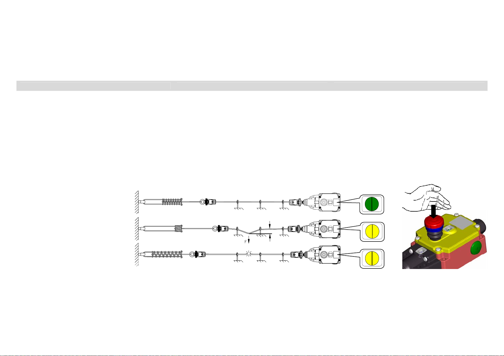
Betriebsstellung des Systems /
System operation setting/
Système opérationnel
Auslösung durch Bediener - Rastung automatisch /
Triggered by user - engages automatically /
Déclenchement par l’utilisateur /verrouillage
automatique
Seilriss - Rastung automatisch /
Cable breakage - engages automatically /
Rupture du câble/verrouillage automatique
Schaltzustandsanzeige / Switching status indicator / Indicateur d’état de commutation
„grün“ / „green“ / «vert»
„gelb“ / „yellow“ / «jaune»
S
„gelb“ / „yellow“ / «jaune»
Integrierter Not-Halt-Taster (Abb.1) Integrated Emergency Stop button (Fig.1) Bouton d’arrêt d’urgence intégré (fig.1)
Abb.1
Die Sicherheits-Seilzugschalter des Typs PSEN rs1.0 haben
einen integrierten Not-Halt-Taster der in einer Gefahrensituation
durch drücken betätigt werden kann. Hierbei werden analog zur
Betätigung des Zugseils die Sicherheitskontakte geöffnet und
der Schalter verrastet. Nach Beseitigung der gefahrbringenden
Situation darf das System manuell, durch ziehen des Not-Halt-
Dok.: 0800000644.doc / Stand : 1 / Ausgabedatum : 28.01.2010 / 2052-10 Blatt 2 von 16
The type PSEN rs1.0 safety cable pull switches are equipped
with an Emergency Stop impact button that can be pressed in
hazardous situations. In the same way as pulling the pull cable,
the safety contacts are opened and the switch is locked. After
eliminating the hazardous situation, the system can be reset
manually to standby mode by pulling the Emergency Stop
Les interrupteurs de sécurité à commande par câble du type
PSEN rs1.0 sont pourvus d’un bouton d’arrêt d’urgence intégré
qui peut être actionné par simple pression en cas de danger.
Les contacts de sécurité s’ouvrent et l’interrupteur est verrouillé
comme lorsque que c’est le câble de traction qui est actionné.
Une fois que tout danger est écarté, le système peut être remis
Vorlage : 0850174292 Orig. 2
Page 3

Tasters, in die Betriebs-bereitschaft zurückgesetzt werden. Der
Not-Halt-Taster ist in geeigneter Weise (z.B. durch Bedachung)
vor direktem Niederschlag (Regen etc.) zu schützen.
Bitte hierzu auch Punkt 3 des Kapitels Montagefolge
berücksichtigen!
button. The Emergency Stop button should be suitably
protected (e.g. covering) from direct precipitation (rain etc.).
Please refer to Point 3 in Section Installation sequence!
manuellement en état de fonctionnement en tirant le bouton
d’arrêt d’urgence. Protéger le bouton d’arrêt d’urgence de
manière appropriée (par ex. en le recouvrant) des précipitations
directes (pluie, etc.).
Veuillez également vous reporter au point 3 de la partie
Déroulement du montage.
Anzeige der Seilspannung Indication of cable tension Affichage de la tension du câble
Über das eingebaute Sichtfenster lässt sich bei der Installation
/Justage der Seilzugstrecke einfach die korrekte Seilspannung
kontrollieren. Für die optimale Seilspannung sind bei der
Justage die Pfeilspitzen der Anzeige mit der Markierung zur
Deckung zu bringen. Die in den PSEN rs1.0 Schaltern
integrierten Federn zum spannen des Seils sind optimal auf die
verschieden Seillängen abgestimmt. Bitte hierzu das Kapitel
Auswahl der Systemkomponenten und Montagefolge beachten.
During installation/adjustment of the cable assembly, the correct
tension of the cable can be checked through the integrated
inspection window. To ensure optimum cable tension as part of
the adjustment procedure, the tips of the indicator arrows
should be aligned with the marking. The cable tensioning
springs integrated in the PSEN rs1.0 switches are optimally
adjusted to the various cable lengths. Please refer to Section
Selection of system components and Installation sequence.
En cas de montage ou de réglage de la ligne de traction du
câble, la tension correcte du câble peut être facilement
contrôlée par la fenêtre d’inspection intégrée. Lors du réglage, il
faut faire coïncider la pointe des flèches de l’indication avec le
repère pour obtenir une tension optimale du câble. Les ressorts
intégrés dans les interrupteurs du type PSEN rs1.0 et destinés
à mettre le câble sous tension sont parfaitement adaptés aux
différentes longueurs de câble. Veuillez vous référer à la partie
Choix des composants du système et Déroulement du
montage.
Schaltzustandsanzeige der Rastung Switching status indicator of locking facility Indicateur d’état de commutation du verrouillage
Über das eingebaute Sichtfenster lässt sich der Schaltzustand
der Rastung und der Kontakte ablesen.
Der verrastete Zustand des Sicherheits-Seilzugschalter wird in
dem Sichtfenster durch gelb signalisiert. (Öffnerkontakte
geöffnet)
Ist der Seilzugschalter betriebsbereit und die Seilstrecke wird
überwacht, wird dies in dem Sichtfenster durch grün
signalisiert. (Öffnerkontakte geschlossen)
The switching status of the locking facility and contacts can be
read off through the integrated inspection window.
Yellow in the inspection window indicates that the safety cable
pull switch is locked (NC contacts open).
Green in the inspection window indicates that the cable pull
switch is ready for operation and the cable assembly is
monitored (NC contacts closed).
Par la fenêtre d’inspection intégrée, il est possible de vérifier
l’état de commutation du dispositif de verrouillage et des
contacts.
L’état verrouillé de l’interrupteur de sécurité à commande par
câble est indiqué dans la fenêtre d’inspection par la couleur
jaune. (Contacts d’ouverture ouverts)
Si l’interrupteur de sécurité à commande par câble est en état
de fonctionnement et si la ligne du câble est surveillée, la
couleur verte s’affiche dans la fenêtre d’inspection. (Contacts
d’ouverture fermés)
Sicherheitshinweise Safety information Consignes de sécurité
• Alle System-Komponenten müssen auf Untergründen
befestigt sein, die sicher alle auftretenden Kräfte aufnehmen
können.
• Eine möglichst gerade Seilführung bewirkt geringe
Reibungskräfte im System, wobei ab einer Systemlänge
von 25 m die Seilunterstützungen nur noch durch
Blockseilrollen erfolgen darf.
Blockseilrollen und weiteres Zubehör sind optional
erhältlich.
• Die Positionierung der Stützpunkte in unregelmäßigen
Abständen verhindert Seilschwingungen, welche ansonsten
eine Fehlauslösung bewirken könnten.
• Das rote Zugseil muss zwischen den Abstützpunkten
genügend Freiraum zum sicheren Greifen und Auslösen
besitzen. Zur Verbesserung der Sichtbarkeit, können
entlang des Zugseils, Markierungsfähnchen an das Seil
Dok.: 0800000644.doc / Stand : 1 / Ausgabedatum : 28.01.2010 / 2052-10 Blatt 3 von 16
• All system components must be mounted on foundations
that are able to reliably absorb all forces that occur.
• The cable mounted as straight as possible will reduce
frictional forces in the system. Only cable pulley
blocks are to be used to support the cable as from a length
of 25 m.
Cable pulley blocks and other accessories are optionally
available.
• Positioning the supports at irregular intervals prevents cable
vibration which could otherwise cause the cable pull system
to trip.
• The red pull cable must have sufficient clearance between
the supports to allow it to be grasped easily and triggered
reliably. To improve visibility, marking flags can be arranged
along the pull cable. These flats, however, must not obstruct
triggering of the emergency stop function.
• Tous les composants du système doivent être fixés à des
structures qui peuvent certainement supporter toutes les
forces appliquées.
• Une trajectoire la plus droite possible du câble entraîne
des efforts de frottement minimes dans le système, à partir
d’une longueur du système de 25 m, les appuis du câble
doivent être munis de poulies.
Les poulies et autres accessoires sont disponibles en
option.
• Le positionnement des points d’appui à intervalles
irréguliers prévient les oscillations du câble qui pourraient
sinon entraîner un déclenchement intempestif.
• Il y doit y avoir suffisamment d’espace libre autour du
câble de traction rouge entre deux points d’appui pour
permettre un accès facile et un déclenchement fiable. Afin
qu’il soit plus visible, il est possible de placer le long du
Vorlage : 0850174292 Orig. 2
Page 4
angebracht werden, die das Auslösen der Not-HaltFunktion nicht behindern dürfen!
• Bei dem Aufbau und Planung einer Seilzugstrecke müssen die
geltenden Vorschriften, sowie der maximal zulässige
Betätigungsweg von S = 400 mm und eine Auslösekraft von
max. F = 200 N, senkrecht zum Seil, berücksichtigt und
eingehalten werden.
• Eine abgewinkelte Seilführung, muss mit geeigneten
Umlenkrollen (Rollendurchmesser ≥ 50 mm) ausgestattet
sein. Die Seilzugstrecke darf maximal um einen Winkel von
180° (z.B. 2x90°) abgewinkelt werden.
• Ein unsachgemäßer Einbau oder Manipulation des
• The design and planning of a pull cable assembly must take
into account and comply with the valid regulations as well as
the maximum permissible actuation range of S = 400 mm and
a maximum triggering force of F = 200 N, vertically with
respect to the cable.
• Suitable deflection pulleys (pulley diameter ≥ 50 mm) must
be used at deflection points in the cable assembly. The
angle deflection in the pull cable assembly must not exceed
180° (e.g. 2x 90°).
• Incorrect installation of or tampering with the cable pull
switch may lead to loss of the personal protection function
and can result in serious or fatal injuries.
Seilzugschalters führt zum Verlust der Personenschutzfunktion und kann zu schweren oder tödlichen Verletzungen
führen.
Identifizierung des Sicherheits-Seilzuschalters / Identification of the safety cable pull switch / Identification de l’interrupteur de sécurité à commande par câble
câble des petits drapeaux de repérage qui ne doivent pas
gêner le déclenchement de la fonction d’arrêt d’urgence.
• Au cours de l’installation et de la planification d’une ligne à
câble de traction, il faut prendre en compte et respecter les
directives en vigueur ainsi que la flèche maximale admissible
de S = 400 mm et une force de déclenchement maxi.
F = 200 N perpendiculaire au câble.
• Dans le cas d’une trajectoire déviée du câble, il faut avoir
recours à des poulies de guidage adaptées (diamètre des
poulies ≥ 50 mm). La ligne du câble de traction peut être
déviée d’un angle maxi. de 180º (par ex. 2 x 90º).
• Une installation ou une manipulation incorrecte de
l’interrupteur de sécurité à commande par câble entraîne
l’annulation de la fonction de protection des personnes et
peut causer des blessures graves, voire mortelles.
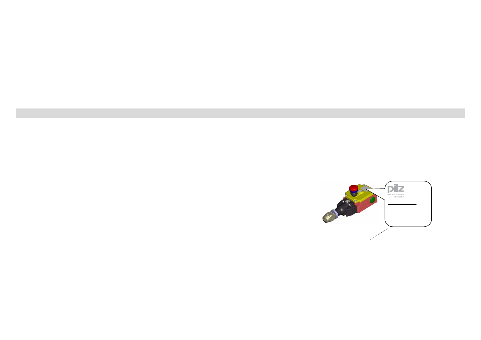
Identifizierung durch Artikelnummer Identification by article number Identification par la référence
Die Artikelnummer des Seilzugschalters finden sie unterhalb
der Benennung auf dem Schalteretikett.
Für die Korrespondenz und Bestellungen bei der Pilz GmbH
bitte diese Nummer angeben.
Identifizierung durch Benennung/ Identification by type designation/ Identification par la désignation
Benennung Designation
PSEN rs1.0 … 175,
PSEN rs1.0 … 300
Die Bennenung unterscheidet sich in
den letzten 3 Stellen (175, 300). Sie
beschreiben die Seilzugfeder. Detaills
siehe Tabelle 1.
PSEN rs1.0 … 175,
PSEN rs1.0 … 300,
The last 3 positions of the designation
differ (175, 300). They describe the
cable pull spring. See Table 1 for
details.
You will find the article number of the cable pull switch below
the designation on the product label.
Please quote this article number in all correspondence and
when placing orders with Pilz GmbH.
Désignation
PSEN rs1.0 … 175,
PSEN rs1.0 … 300
La désignation diffère au niveau des
trois dernières positions (175, 300).
Elles correspondent au ressort de
tension. Voir le tableau 1 pour plus de
détails.
Baujahr Year of manufacture Année de fabrication
Im Fertigungscode ist das Baujahr
verschlüsselt.
Die 2. Stelle beschreibt die Dekade.
A = 1980 … 1989
B = 1990 … 1999
C = 2000 … 2009
D = 2010 … 2019
E = 2020 … 2029
Die 3. Stelle beschreibt unverschlüsselt
das Jahr.
Beispiel: GC9-H
Baujahr verschlüsselt: C9
Baujahr: 2009
The year of manufacture is encrypted
in the production code.
The 2nd position denotes the decade.
A = 1980 … 1989
B = 1990 … 1999
C = 2000 … 2009
D = 2010 … 2019
E = 2020 … 2029
Unencrypted, the 3rd position denotes
the year.
Example: GC9-H
Year of manufacture encrypted: C9
Year of manufacture: 2009
L’année de fabrication est codée dans
le code de fabrication.
La deuxième position correspond à la décennie.
A = 1980 à 1989
B = 1990 à 1999
C = 2000 à 2009
D = 2010 à 2019
E = 2020 à 2029
La troisième position correspond à l’année
non codée.
Exemple : GC9-H
Année de fabrication codée : C9
Année de fabrication : 2009
La référence de l’interrupteur de sécurité à commande par
câble se trouve juste en dessous de la désignation sur
l’étiquette de l’interrupteur.
Prière de mentionner cette référence à la commande ou sur
toute correspondance adressée à la société Pilz GmbH.
PSEN rs1.0…
570300
…
GC9-H
Fertigungscode /
Production code/
Code de fabrication
Benennung /
Type designation /
Désignation
Dok.: 0800000644.doc / Stand : 1 / Ausgabedatum : 28.01.2010 / 2052-10 Blatt 4 von 16
Vorlage : 0850174292 Orig. 2
Page 5
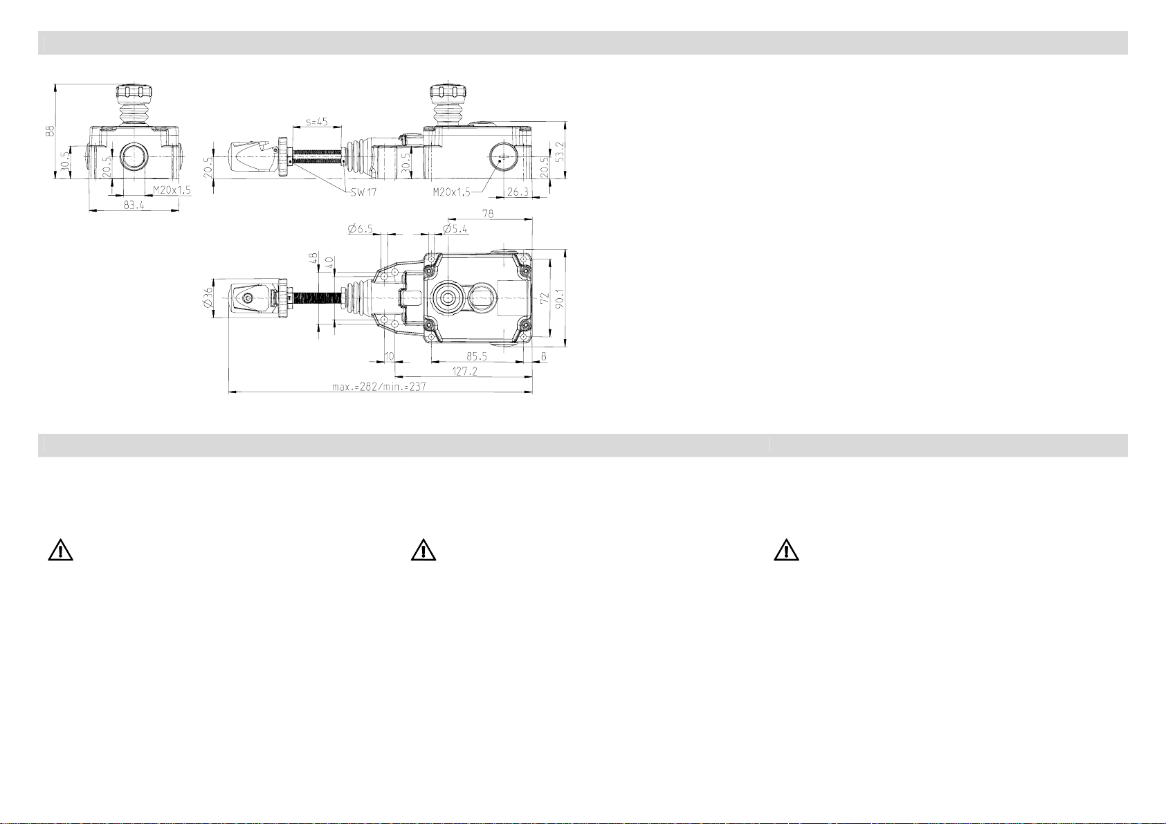
Abmessungen / Dimensions / Dimensions
PSEN rs 1.0
Alle Abmessungen in Millimeter / All dimensions in millimetres / Toutes les dimensions sont indiquées en mm.
Montage Installation Montage
Die Montage darf nur durch autorisiertes Fachpersonal
erfolgen.
Verunreinigungen können die Funktion des Systems stören.
Dem ist vorzubeugen.
Die Montage muss nach DIN EN 1088 erfolgen.
Maßnahmen zur Verringerung der
Umgehungsmöglichkeiten sind besonders zu
berücksichtigen.
Installation should only be carried out by authorised technical
personnel.
Soiling can cause malfunctions in the system.
Soiling must therefore be avoided.
Installation must be carried out in accordance with
DIN EN 1088. Particular attention must be paid to
measures designed to reduce the possibilities of
bypassing the system.
Le montage ne doit être effectué que par du personnel qualifié
autorisé.
Des saletés risquent de perturber le bon fonctionnement du
système. Il faut les éviter.
Le montage doit être effectué conformément à la
norme DIN EN 1088. Tenir en particulier compte des
mesures destinées à réduire les possibilités d e
contournement des dispositifs de sécurité.
Auswahl der Systemkomponenten Selection of system components Choix des composants du système
Für eine sachgemäße und sicherheitskonforme Ausführung des
Seilzugsystems muss am Gegenlager eine Seilzugfeder
vorgesehen werden. Hierdurch ist ein richtungsunabhängiges
Auslösen an jeder Stelle der Seilstrecke möglich. Um diesen
Anspruch schnell und einfach erfüllen zu können empfehlen wir
den Einsatz der Seilzugfedern mit integriertem
Überdehnungsschutz (siehe Tabelle 1).
Weiteres Befestigungs- und Montagematerial sowie Seil kann
optional erworben werden, eine ausführliche Übersicht finden
Sie im Kapitel Zubehör.
Dok.: 0800000644.doc / Stand : 1 / Ausgabedatum : 28.01.2010 / 2052-10 Blatt 5 von 16
A cable pull spring must be installed at the end support to
ensure correct and safety-compliant installation of the cable pull
system. This makes it possible to trip the system, irrespective of
direction, at any point along the cable assembly. In order to
meet this requirement quickly and simply we recommend the
use of cable pull springs with integrated overextension guard
(see Table 1).
Other installation and assembly material as well as the cable
are optionally available. You will find a detailed overview in
Section Accessories.
Pour que le système à commande par câble soit conforme à la
fois du point de vue de la technique et de la sécurité il faut fixer
un ressort de tension à la butée. Il est ainsi possible de
déclencher l’arrêt d’urgence indépendamment de la direction à
partir de chaque point de la ligne de câble. Pour répondre
rapidement et simplement à cette exigence, nous vous
recommandons d’utiliser les ressorts de tension à protection
intégrée contre l’allongement excessif (voir tableau 1).
Le matériel supplémentaire de fixation et de montage comme le
câble peut être commandé en option ; vous trouverez plus de
détails dans la partie Accessoires.
Vorlage : 0850174292 Orig. 2
Page 6

Seilzugfeder / Cable pull spring / Ressort de tension
Tabelle 1 / Table 1 / Tableau 1
PSEN rs1.0-Typ / PSEN rs1.0-type / Type PSEN rs1.0 PSEN rs spring 175 PSEN rs spring 300
Sachnummer / Part number / Numéro de référence 570310 570311
L
[mm] 383 483
0 min.
L
[mm] 487 653
max.
ØD [mm] 42 51
Die Seilzugfedern sind incl. Schnellbefestigung und einer
Augenschraube
DIN 444 - M12 x 50
Bei der Montage und Justage des Seilzugschalters sind die
physikalischen Längenänderungen des Seils durch
Temperaturschwankungen zu berücksichtigen.
Die Tabelle 2 zeigt die zulässigen Abspannlängen in
Abhängigkeit der zu erwarteten Temperaturdifferenz.
Zusätzlich kann dem Diagramm die maximal zulässigen
Abspannlängen bei verschiedenen Federkräften in den
Schaltertypen entnommen werden. Des Weiteren ist eine
Auswahl des Seilzugschalters nach den zu erwartenden
Temperaturschwankungen möglich.
The cable pull springs include a quick-action cable grip and an
eyebolt
DIN 444 - M12 x 50
The physical changes in the length of the cable caused by
temperature fluctuations must be taken into account during the
installation and adjustment of the cable pull switch.
Table 2 shows the permissible span in relation to the expected
temperature difference.
The diagram additionally shows the maximum permissible spam
at different spring forces in the different types of switches. With
this table it is also possible to select the cable pull switch
according to the expected temperature fluctuations.
Les ressorts de tension incluent une fixation rapide et une vis à
œillet
DIN 444 – M12 x 50
Il faut prendre en compte les variations physiques de la
longueur du câble engendrées par les fluctuations de la
température au cours du montage et du réglage de
l’interrupteur de sécurité à commande par câble.
Le tableau 2 présente les longueurs d’ancrage admissibles en
fonction de la différence de température prévue.
Les longueurs d’ancrage maximales admissibles pour diverses
tensions du ressort peuvent également être déterminées dans
le tableau à partir du type de l’interrupteur. De plus, il est
possible de choisir l’interrupteur de sécurité à commande par
câble selon les fluctuations de température prévues.
Tabelle 2 / Table 2 / Tableau 2
1 2 3 4 5 6 7 8 9
fluctuation
schwankung
in Kelvin / Max.
in Kelvin / Max.
Max. temperature
max. Temperatur-
PSEN rs1.0-175
PSEN rs1.0-300 Abspannlänge max. 75 Meter / Span max. 75 m / Longueur d’ancrage maxi. 75 m
Dok.: 0800000644.doc / Stand : 1 / Ausgabedatum : 28.01.2010 / 2052-10 Blatt 6 von 16
temp. en Kelvin
Variation maxi. de
Abspannlänge Lmax. in Meter [m] / Span Lmax. in metres [m] / Longueur d’ancrage Lmaxi. en mètres [m]
10
11
12
13
14
15
16
17
18
19
20
22
24
26
28
30
32
34
36
38
40
+/- 55 K
+/- 50 K
+/- 45 K
+/- 35 K
+/- 25 K
+/- 20 K
Abspannlänge max. 37,5 Meter / Max. span 37.5 m /
+/- 13 K
Longueur d’ancrage maxi. 37,5 m
+/- 7 K
+/- 4,5 K
42
44
46
48
50
55
60
Bei der Planung bzw.
Installation sind in
Abständen von
65
70
75
2–5 m
Seilunterstützungen
vorzusehen. Hierzu
bitte die
Sicherheitshinweise
beachten.
The planning and
installation should
include
cable supports at 2–5
m intervals. Please
refer to Safety
information.
Il faut prévoir en
cours de planification
et d’installation des
appuis de câble à
intervalles de 2 à
5 m. Veuillez
respecter ici les
Consignes de
sécurité.
Vorlage : 0850174292 Orig. 2
Page 7

Montagefolge Installation sequence Déroulement du montage
1
2
3
Lagerpunkt mit Seilzugfeder anbringen; Zugseil montieren:
Ummantelung muss
wie dargestellt in den Schnellspannkopf einlegen und sichern
im Klemmbereich entfernt werden, Seil
Abspannlänge / Bracing length / Longueur d’ancrage
Lg = 200 mm
PSEN rs1.0 mit 4 Schrauben M5
oder M6 befestigen.
Maximales Anzugsmoment
M = 2 Nm
Secure the PSEN rs1.0 switch with
4 M5 or M6 screws.
Maximum tightening torque
M = 2 Nm
1.1A
2 - 5 m
1.2A
Attach mount with cable pull spring; install pull cable: The
sheathing must
place cable as illustrated in the quick-action cable grip and
secure
be removed at the cable clamping point,
La = 150 mm
Fixer le PSEN rs1.0 avec 4 vis M5
ou M6.
Couple de serrage maximal
M =2 Nm
1.3A
4
Accrocher le ressort de tension au point de fixation; installer
le câble de traction : La gaine doit être enlevée dans la zone
de serrage, placer et fixer solidement le câble dans la tête du
dispositif de serrage rapide (voir fig.).
Abstand zu den
Stützpunkten
beachten. Die 1.
Seilunterstützung
zum Schalter hin ist
nach La =150 mm
vorzusehen. Auf der
Seite der
Gegenfeder den
Abstand Lg =200
mm, für einen
ausreichenden
Auslöseweg des
Schalters beachten.
Stützpunkte im
Abstand von 2 – 5 m
einrichten
Maintain distance to
the supports. The 1st
support from the
switch must be
positioned after La =
150 mm. The
distance on the
counterspring end
must be Lg =
200 mm to ensure
the triggering range
of the switch is not
obstructed.
Install supports at 2 5 m intervals
17
Respecter l’intervalle
entre les points
d’appui. Le 1e appui
du câble en direction
de l’interrupteur doit
se trouver à une
distance minimale
La=150 mm.
Respecter du côté
du ressort de rappel
l’écart Lg=200 mm
pour assurer une
course de
déclenchement
suffisante de
l’interrupteur.
Disposer les points
d’appui à une
distance comprise
entre 2 et 5 m.
Seilzugschalter müssen so
positioniert werden das in
Gefahrensituationen das Seil bzw.
der Not-Halt Taster ohne
Hindernisse erreicht werden kann.
Dok.: 0800000644.doc / Stand : 1 / Ausgabedatum : 28.01.2010 / 2052-10 Blatt 7 von 16
Cable pull switches must be
installed in such a way that the
cable or the Emergency Stop
button can be reached without
obstruction in hazardous situations.
Les interrupteurs de sécurité à
commande par câble doivent être
positionnés de telle sorte que le
câble ou le bouton d’arrêt
d’urgence soit accessible sans
obstacle en cas de danger.
Anzeige Seilspannung /
Cable tension indicator /
Indication de la tension du câble
48
40
10
72
85,5
Vorlage : 0850174292 Orig. 2
Page 8

A
4
5
die den vorherrschenden Betriebsbedingungen entspricht.
Bei starker Veränderung der Umgebungstemperatur erfährt
des Zugseil eine Längenänderung. Große Seillängen
führen unter diesen Bedingungen zur häufigen
Veränderung der Grundeinstellung.
Abhilfe durch: Nachjustage (Punkt 5) oder Kürzung der
Seillänge.
Justageschraube /
djustment /
Vis de réglage
17
Seilstrecke von Hand mit der
Justageschraube oder einem
Maulschlüssel (SW17) durch
eindrehen einjustieren, bis die
Pfeilspitzen der Anzeige
„Seilspannung“ mit der Markierung zur
Deckung kommen.
Schnellspannkopf hierbei festhalten,
um ein Verdrehen des Zugseils zu
vermeiden.
Im Anschluss die Justageschraube
durch Kontern der Sechskantmutter
gegen lösen sichern.
Die Grundeinstellung sollte bei einer Temperatur erfolgen,
The basic adjustment of the cable assembly should take
place at a temperature that corresponds to the prevailing
operating conditions.
The pull cable is subject to changes in lengths if there are
large variations in the ambient temperature. The basic
setting of longer section of cable can often change under
these conditions.
Changes in cable length can be remedied by readjustment
(Point 5) or shortening the cable.
Zugseil mit
Schnellspannkopf
verbinden
(siehe Punkt 1).
Zugseil vorspannen.
Manually adjust the cable assembly by
turning the adjusting screw or using a
(WAF17) open-ended spanner until
the arrow tips of the "Cable tension
indicator" are aligned with the marking.
While doing so, brace the quick-action
cable grip to prevent the cable
twisting.
After adjustment, secure the adjusting
screw by locking the hexagon nut.
Connect pull cable to
quick-action cable grip
(see Point 1).
Pretension pull cable.
Ajuster manuellement la ligne de câble
en tournant à l’aide de la vis de réglage
ou d‘une clé à fourche (ouverture 17)
jusqu’à ce que les pointes des flèches
de l’indication « tension du câble »
coïncident avec le repère.
Fixer la tête du dispositif de serrage
rapide pour éviter que le câble de
traction ne tourne.
Puis, fixer solidement la vis de réglage
en bloquant l’écrou hexagonal pour
éviter qu’elle ne se dévisse.
Attacher le câble de
traction à la tête du
dispositif de serrage
rapide (voir point 1).
Tendre le câble de
traction.
Le réglage de base doit être réalisé à une température qui
correspond aux conditions de fonctionnement
prédominantes.
Si la température ambiante fluctue fortement, la longueur
du câble de traction varie. Les longueurs de câble
importantes entraînent dans ces conditions des variations
fréquentes du réglage de base.
Solution : effectuer un réglage ultérieur (point 5) ou
raccourcir le câble.
Anzeige
Seilspannung /
Cable tension
indicator /
Indication de la
tension du
câble :
Anzeige
Seilspannung /
Cable tension
indicator /
Indication de la
tension du
câble :
Dok.: 0800000644.doc / Stand : 1 / Ausgabedatum : 28.01.2010 / 2052-10 Blatt 8 von 16
Vorlage : 0850174292 Orig. 2
Page 9

Mechanische Funktionsprüfung / Mechanical function check / Contrôle des fonctions mécaniques
PSEN rs1.0…
6
Not-Halt Taster am
blauen Griffring hochziehen
- Sicherheitskontakte
geschlossen –
Zugseil betätigen;
- Sicherheitskontakte geöffnet –
Funktionsprüfung mit Betätigung
des Not-Halt Tasters wiederholen
Die Bedienbarkeit des Stellteils
muss sichergestellt sein.
PSEN rs1.0…
Pull Emergency Stop impact button
at blue grip
- Safety contacts
closed –
Pull cable;
- Safety contacts open -
Repeat function check with
actuation of the emergency stop
impact button
Operability of the control element
must be ensured.
PSEN rs1.0…
Lever la bague bleue du bouton
d’arrêt d’urgence
- Contacts de sécurité fermés Actionner le câble de traction ;
- Contacts de sécurité ouverts -
Répéter le contrôle du
fonctionnement en actionnant le
bouton d’arrêt d’urgence.
La facilité d’utilisation de l’élément
de commande doit être garantie.
F max. 200 N
S max. 400 mm
Das Zugseil mehrmals kräftig betätigen – um ein Setzen der
Seilzugstrecke herbeizuführen.
Falls erforderlich Seilstrecke durch Justageschraube /
Spannschloss nachspannen.
To settle the pull cable assembly, pull the cable with
considerable effort several times.
If necessary, retension cable assembly by means of the
adjusting screw/turn buckle.
Actionner fortement plusieurs fois le câble de traction pour
que la ligne du câble de traction se place correctement.
Serrer, si nécessaire, la ligne du câble à l’aide de la vis de
réglage ou du tendeur.
Dok.: 0800000644.doc / Stand : 1 / Ausgabedatum : 28.01.2010 / 2052-10 Blatt 9 von 16
Vorlage : 0850174292 Orig. 2
Page 10

Elektrischer Anschluss Electrical connection Raccordement électrique
Der elektrische Anschluß darf nur durch autorisiertes
Fachpersonal erfolgen
1. - Deckel abnehmen -
Hierzu Deckelschrauben mit einem Schraubendreher lösen und Deckel abnehmen.
2. - elektrischer Anschluss -
Die elektrischen Kontakte der Schaltglieder haben
Schraubanschlüsse M3,5. Kontaktbelegung siehe Abschnitt
„Schaltsymbol und Schaltdiagramm“.
Der Anschluss muss als Litze mit Aderendhülse oder
eindrahtig mit den Leiterquerschnitten 0,5 –1,5mm² erfolgen.
3. - Deckel verschließen -
Deckel wie abgebildet auf das Gehäuse aufsetzen und
Deckelschrauben mit einem Drehmoment von
2 Nm anziehen.
Sicherheitshinweise
• Der Dichtbereich zwischen Gehäuse und Deckel
muss frei von Fremdkörpern sein!
• Anzugsdrehmomente beachten!
• Der Seilzugschalter darf nur mit geschlossenem
Deckel betrieben werden!
Anzugsdrehmoment der
Deckelschrauben 2 Nm /
Tighteneing torque of
cover retaining screws
2 Nm /
Moment de rotation
des vis du couvercle de
2 Nm
Electrical connection should only be carried out by authorised
technical personnel.
1. - Remove cover -
For this purpose, undo cover screws with a
screwdriver and detach cover.
2. - Electrical connection -
The electrical contacts of the switching elements have M3.5
screw connections. See "Circuit Symbol and Circuit
Diagram" for contact assignments.
The connection requires a stranded wire with ferrule or a
single wire with a cross section of 0.5 –1.5 mm².
3. - Close cover -
Place cover on enclosure as illustrated and tighten cover
retaining screws to a torque of
2 Nm.
Safety information
• There must be no foreign particles in the sealing
area between the enclosure and cover!
• Observe specified tightening torque requirements!
• Only operate the cable pull switch with the
cover closed!
Einbauschalter S1+S2 / built-in switches S1+S2 / interrupteurs intégrés S1+S2
Anzugsdrehmoment der Kontaktschrauben 0,8 Nm /
Tighteneing torque of contact screws 0.8 Nm /
Moment de rotation des vis de contact de 0,8 Nm
Le raccordement électrique ne doit être effectué que par un
personnel qualifié autorisé.
1. - Retirer le couvercle -
Desserrer les vis du couvercle à l’aide d’un tournevis et
retirer le couvercle.
2. - Raccordement électrique -
Les contacts électriques des éléments de contact sont fixés
par des vis M3,5. Consulter la partie Symbole de
commutation et schéma de commutation pour l’affectation
des contacts.
Le raccordement doit être réalisé par un toron à manchon
ou unifilaire avec une section de conducteur comprise
entre 0,5 et 1,5mm².
3. - Refermer le couvercle
Poser le couvercle sur le boîtier comme indiqué sur la
figure et visser les vis du couvercle en appliquant un couple
de serrage de 2 Nm.
Consignes de sécurité
• Il ne doit y avoir aucun corps étranger dans la zone
d’étanchéité située entre le boîtier et le couvercle.
• Tenir compte des couples de serrage !
• L’interrupteur de sécurité à commande par câble ne
doit être utilisé qu’avec le couvercle fermé !
Dok.: 0800000644.doc / Stand : 1 / Ausgabedatum : 28.01.2010 / 2052-10 Blatt 10 von 16
Vorlage : 0850174292 Orig. 2
Page 11

p
/
/
/
/
/
/
/
/
/
/
/
/
Systembeschreibung – Applikationsvorschlag / System description – Suggested application / Descri ption du système – Suggestion d’application
Applikationsvorschlag
Applikationsvorschlag
Suggested application
Suggestion d’application
Applikationsvorschlag
Suggested application
Suggestion d’application
mit redundanter Auslegung auch in der Leistungsebene /
Suggested application
with redundant configuration also on the power level /
Suggestion d’application
avec configuration redondante même en puissance
Not-Halt-Kreis /
Emergency stop circuit /
Circuit d’arrêt d’urgence
L1 L2 L3
M
PSEN rs1.0
Reset
PSEN rs1.0
Sicherheits-Relais-Kombination /
Safety relay combination/
Combinaison de relais de sécurité sécurité
Not-Halt-Kreis /
Emergency stop circuit /
Circuit d’arrêt d’urgence
M
Reset
PSEN rs1.0
Sicherheits-Relais-Kombination /
Safety relay combination /
Combinaison de relais de sécurité
Not-Halt-Kreis /
Emergency stop circuit /
Circuit d’arrêt d’urgence
L1 L2 L3
M
Das Gesamtkonzept der Steuerung, in die der Seilzugschalter PSEN rs1.0-… eingebunden ist, ist durch den Endverbraucher/Maschinenkonstrukteur entsprechend
DIN EN ISO 13849-2 zu validieren. /
The overall control concept which includes the cable pull switch PSEN rs1.0-… must be validated by the end user/machine designer in accordance with DIN EN ISO 13849-2. /
Le concept complet de la commande dans laquelle l’interrupteur de sécurité à commande par câble PSEN rs1.0-… est intégré, doit être validé par le consommateur
final/constructeur de machines selon la DIN EN ISO 13849-2
Elektrische Funktionsprüfung Electrical function check Contrôle du fonctionnement électrique
Seilzug-Sicherheitssystem durch ziehen am blauen Griffring des
Not-Halt-Tasters aktivieren.
Anlage/Maschine starten.
Zugseil / Not-Halt-Taster betätigen – bewirkt sofortiges Öffnen
der Sicherheitskontakte.
Erst nach erneutem ziehen am blauen Griffring – schließen die
Sicherheitskontakte.
Activate the cable pull safety system by pulling at the blue grab
ring on the Emergency Stop button.
Start system/machine.
Pull cable/press Emergency Stop button – the safety contacts
open immediately.
Pull the blue grab ring again to close the safety contacts.
Actionner le système de sécurité à commande par câble en
tirant sur la bague bleue du bouton d’arrêt d’urgence.
Démarrer l’installation ou la machine.
Actionner le câble de traction ou le bouton d’arrêt d’urgence qui
entraîne l’ouverture immédiate des contacts de sécurité.
Ce n’est qu’après avoir tiré une nouvelle fois sur la bague bleue
que les contacts de sécurité se ferment.
Elektrische Daten / Electrical data / Caractéristiques électriques
Bemessungsisolationsspannung /Rated insulation voltage/ U
Tension assignée d’isolement
Bemessungsstoßspannungsfestigkeit / Rated surge voltage U
strength / Résistance aux ondes de surtension assignée
Konv. thermischer Strom / Conv. thermal current / I
Courant thermique conv.
Bemessungsbetriebsspannung / Rated operating voltage/ U
Tension assignée de d'emploi
Gebrauchskategorie / Utilization category / АС-15, U
Catégorie d’usage U
DC-13, U
U
Dok.: 0800000644.doc / Stand : 1 / Ausgabedatum : 28.01.2010 / 2052-10 Blatt 11 von 16
250 V 250 V 250 V
i
2,5 kV 2,5 kV 2,5 kV
im
10 A 10 A 10 A
the
240 V 240 V 240 V
e
Ie240 V /3 А, АС-15, U
e
Ie120 V/6 А U
e
Ie125 V /0,55 A U
e
Ie250 V / 0,27 A, DC-13, U
e
Ie120 V/6 А U
e
Ie125 V /0,55 A U
e
Ie240 V /3 А, АС-15, U
e
Ie250 V / 0,27 A, CD-13, U
e
Ie240 V /3 А,
e
Ie120 V/6 А
e
Ie125 V /0,55 A
e
Ie250 V / 0,27 A,
e
Vorlage : 0850174292 Orig. 2
Page 12

Zwangsöffnung / Positively driven opening / Ouverture nach IEC/EN 60947-5-1, Anhang K As per IEC/EN 60947-5-1, Annex K selon la norme CEI/EN 60947-5-1,
forcée annexe K
Kurzschlussschutzeinrichtung / Short-circuit protection / Schmelzsicherung 6 A DII Typ gG Fuse 6 A DII, Type gG fusible 6 A DII du type gG
Protection contre court-circuit
Schutzklasse / Protection class / Classe de protection I I I
Mechanische Daten / Mechanical data / Caractéristiques mécaniques
Gehäuse / Enclosure/ Boîtier Al-Druckguss Aluminium pressure die-casting aluminium coulé sous pression
Deckel / Cover / Couvercle Al-Druckguss Aluminium pressure die-casting aluminium coulé sous pression
Betätigung / Operating element / Commande Schnellklemmvorrichtung Quick-action cable grip dispositif de serrage rapide
mit integriertem Spannschloss with integrated turnbuckle avec tendeur intégré
(Zn-Druckguss / St) (zinc pressure die-casting / St) (zinc coulé sous pression/acier)
Not-Halt-Einrichtung /Emergency stop device /
Dispositif d’arrêt d’urgence
Umgebungstemperatur / Ambient temperature / -30 °C bis +80 °C -30 °C to +80 °C de -30 °C à +80 °C
Température ambiante (keine Vereisung/ keine Kondensation) (no icing/no condensation) (aucun givrage/ aucune condensation)
Kontaktart / Contact type / Type de contact siehe Kapitel See Section voir la section
(2 Einbauschalter S1+ S2) (2 built-in switch S1+ S2) (2 interrupteurs intégrés S1+ S2)
Rasteinrichtung / Latching device / Dispositif de verrouillage nach IEC 60947-5-5, As per IEC 60947-5-5, selon les normes CEI 60947-5-5,
DIN EN 60947-5-5, DIN EN 60947-5-5, DIN EN 60947-5-5 et
ISO 13850 (DIN EN 418) ISO 13850 (DIN EN 418) ISO 13850 (DIN EN 418)
Rückstellung der Rastung / Latch reset / ziehen des Not-Aus Pull Emergency Stop tirer sur le dispositif d’arrêt d’urgence
Réinitialisation du verrouillage nach IEC/EN 60947-5-5 As per IEC/EN 60947-5-5 selon la norme CEI/EN 60947-5-5
Mechanische Lebensdauer / Mechanical life / nach IEC 60947-5-5 As per IEC 60947-5-5 selon la norme CEI 60947-5-5
Durée de vie mécanique max. 1 x 10⁵ Schaltspiele max. 1 x 10⁵ switching operations maxi. 1 x 10⁵ opérations
Seillänge / Cable length / Longueur du câble
PSEN…300 = 75 m PSEN…300 = 75 m PSEN…300 = 75 m
(Tabelle 3 beachten) (see Table 3) (consulter le ta bleau 3)
Seil ∅ / Cable ∅ / Diamètre du câble ∅ D = ∅ 2 - 5 mm
Schalthäufigkeit / Switching frequency / Fréquence de commutation ≤ 20/min. ≤ 20/min. ≤ 20/min
Befestigung / Mounting / Fixation 4 х М6 oder 4 x M5 4х М6 or 4x M5 4 х М6 ou 4 x M5
Anschlussart / Type of connection / Type de raccordement 8 Schraubanschlüsse (М3,5) 8 screw connections (M3.5) 8 raccordements vissés (М3,5)
Leiterquerschnitte / Conductor cross sections / Eindrähtig 0,5 – 1,5 mm2 Single-wire 0.5 – 1.5 mm2 unifilaires 0,5 à 1,5 mm2
Sections des conducteurs Litze mit Aderendhülse 0,5 – 1,5 mm2
Kabeleinführung / Cable entry / Entrée du câble 3 х M20x1,5 3х M20x1.5 3 х M20x1,5
Gewicht / Weight / Poids siehe Datenblätter für Schaltgeräte See datasheets for switching devices
Einbaulage / Installation position / Position de montage beliebig Any libre
Schutzart / Type of protection / Degré de protection IP67 nach IEC/EN 60529 IP67 as per IEC/EN 60529 IP67 selon la norme CEI/EN 60529
Hinweis / Note / Renseignement
Werden Zuhaltungen / Positionsschalter hintereinander geschaltet, dann wird der Performance Level nach DIN EN 13849-1 reduziert. Der Grund ist eine verringerte Fehlererkennung.
The performance level in accordance with DIN EN 13849-1 is reduced if latching devices/position switches are connected in series. This is due the fact that fault recognition is reduced.
Si des verrouillages / interrupteurs de position sont commutés les uns après les autres, le niveau de performance est réduit selon la norme DIN EN 13849-1. Cela est dû à une reconnaissance
réduite des erreurs.
PA, glasfaserverstärkt PA, glass fibre-reinforced polyamide, renforcé par fibres de verre
Schaltsymbol und Schaltdiagramm Circuit symbol and circuit diagram
je nach Typ
L
PSEN…175 = 37,5 m
max:
depending on type
L
PSEN…175 = 37.5 m
max:
D = ∅ 2 - 5 mm
Stranded wire with ferrule
0.5 – 1.5 mm2
Symbole de commutation et schéma
de commutation
selon le type
L
PSEN…175 = 37,5 m
maxi. :
D = ∅ 2 à 5 mm
toron avec manchon 0,5 à 1,5 mm2
consulter les fiches techniques pour
les interrupteurs
Dok.: 0800000644.doc / Stand : 1 / Ausgabedatum : 28.01.2010 / 2052-10 Blatt 12 von 16
Vorlage : 0850174292 Orig. 2
Page 13

Kennzahlen für Sicherheitstechnik / ID for safety engineering / Chiffres pour la technique de sécurité
B10d 2 x 10⁵ Zyklen 2 x 10⁵ cycles 2 x 10⁵ cycles
Vorschriften / Standards / Directives
VDE 0660 T100, DIN EN 60947-1, IEC 60947-1
VDE 0660 T200, DIN EN 60947-5-1, IEC 60947-5-1
VDE 0660 T210, DIN EN 60947-5-5, IEC 60947-5-5
ISO 13850
EG-Konformität / EC conformity / Conformité CE
Zulassungen / Approvals / Homologations
BG
CSAUS A300
C
Schaltdiagramm und Schaltsymbol / Circuit diagram and circuit symbol / Schéma de commutation et symbole de commutation
Kontaktart / Contact type / 2 x (1 Öffner, 1Schließer (Zb)) / 2x (1 NC contact, 1 NO contact (Zb)) / 2 x (1 contact à ouverture, 1 contact à fermeture (Zb))
Type de contact
Schaltglied / Switching
U1Z / U1Z
element / Elément de contact
Schaltsymbol /
Circuit symbol /
Symbole de commutation
S1 S2
Schleichschaltglied / Slow-action switching element / Contact à rupture lente
Schaltdiagramm /
Circuit diagram /
Schéma de commutation
Ein / On / Marche
Aus / Off / Arrêt
Rastung / Latch / Verrouillage
Die Angaben der Zugkraft sind vom verwendeten
Typ abhängig. (PSEN...175/PSEN...300)
Toleranzen: Schaltpunkt +/- 0,5 mm
Betätigungskraft +/- 15 %
The pulling force data depend on the type of switch
used (PSEN...175/PSEN...300)
Tolerances: Switching point +/- 0.5 mm
Actuating force +/- 15%
Les données relatives à l’effort de traction dépendent
du type utilisé. (PSEN...175/PSEN...300)
Tolérances : Point de contact ± 0,5 mm
Force d’actionnement +/- 15 %
Rastung / Latch / Verrouillage
Dok.: 0800000644.doc / Stand : 1 / Ausgabedatum : 28.01.2010 / 2052-10 Blatt 13 von 16
Vorlage : 0850174292 Orig. 2
Page 14

Instandhaltung / Wartung Maintenance / Service Entretien / Maintenance
- Das Seilzugsystem muss in regelmäßigen Abständen
inspiziert und gewartet werden. Die Größe dieser Intervalle
ist abhängig von Umwelteinflüssen und den
Betriebsbedingungen.
- Korrekte Seilspannung und die Not-Halt Funktion der
Seilstrecke überprüfen und wenn erforderlich
nachjustieren.
- Nach einer Wartung / Instandsetzung sollte das System
durch mehrmaliges Betätigen des Zugseils auf korrekte
Funktion überprüft werden. Es ist sicherzustellen, dass der
Seilzugschalter ordnungsgemäß verrastet und sich auch
wieder rückstellen lässt.
- Bei einem Defekt am Schaltsystem oder der
Rasteinrichtung ist der Seilzugschalter auszutauschen.
- The cable pull system must be inspected and serviced at
regular intervals. The extent of these intervals depends on
the ambient and operating conditions.
- Check correct cable tension and the emergency stop
function of the cable assembly and readjust if necessary.
- After servicing/maintenance, check that the system is
operating correctly by pulling the pull cable several times.
Make sure that the cable pull switch engages and resets
correctly.
- Replace the cable pull switch if the switching system or the
latching device is defective.
- Le système à câble de traction doit être inspecté et
entretenu à intervalles réguliers. Cet intervalle de temps
dépend des conditions ambiantes et des conditions
d’utilisation.
- Contrôler et, si nécessaire, régler la tension correcte de
câble et la fonction d’arrêt d’urgence de la ligne de câble.
- Le bon fonctionnement du système devrait être vérifié en
actionnant plusieurs fois le câble de traction après toute
opération d’entretien ou de maintenance. Il faut s’assurer
que l’interrupteur de sécurité à commande par câble est
convenablement verrouillé et qu’il peut également être
réinitialisé.
- En cas de défaillance du système de commutation ou du
dispositif de verrouillage, l’interrupteur de sécurité à
commande par câble doit être remplacé.
Haftungsausschluss
Bei Verletzung der Anweisungen (bestimmungsgemäßer
Gebrauch, Sicherheitshinweise, Montage und Anschluß durch
geschultes Personal, Prüfung auf sichere Funktion) erlischt die
Herstellerhaftung.
Liability disclaimer
Failure to follow these instructions (intended use, safety
instructions, installation and connection by trained personnel,
safe function test) will invalidate any liability.
Exclusion de la responsabilité
La responsabilité du fabricant est annulée si les instructions ne
sont pas respectées (emploi conforme à l’utilisation prévue,
consignes de sécurité, montage et branchement effectués par
un personnel ayant reçu la formation nécessaire, contrôle de la
sécurité de fonctionnement).
Zubehör / Accessories / Accessoires
Seil-Ø - Mantel-Ø / Cable Ø - Sheath Ø / Diamètre du câble, diamètre de la gaine
PSEN rs rope d3 / d4 50 m 570314
PSEN rs rope d3 / d4 100 m 570315
Seilzugfeder / Cable pull spring / Ressort de tension
PSEN rs spring 175 570310
PSEN rs spring 300 570311
Umlenkrolle Ø75 mm / Deflection pulley Ø 75 mm / Poulie de guidage de 75 mm de
diamètre
PSEN rs pulley 75
Blockseilrolle, drehbar... / Pulley block, pivoted... / Poulie pivotante…
PSEN rs pulley flex
Die deutsche Sprachfassung ist die Originalbetriebs- und Montageanleitung. Bei anderen Sprachen handelt es sich um die Übersetzung der Originalbetriebs- und Montageanleitung.
The original operating and installation instructions are the German language version. Other languages are a translation of the original operating and installation instructions.
La version allemande est la langue d’origine des instructions de service et de montage. Les autres langues ne sont qu’une traduction des instructions de service et de montage en langue
allemande.
570312
570313
Dok.: 0800000644.doc / Stand : 1 / Ausgabedatum : 28.01.2010 / 2052-10 Blatt 14 von 16
Vorlage : 0850174292 Orig. 2
Page 15

► Technischer Support
+49 711 3409-444
► …
In vielen Ländern sind wir durch
unsere Tochtergesellschaften und
Handelspartner vertreten.
Nähere Informationen entnehmen
sie bitte unsere Homepage oder
nehmen sie Kontakt mit unserem
Stammhaus auf.
► Technical Support
+49 711 3409-444
► …
In many countries we are
represented by our subsidiaries and
trading partners.
Please visit
our Homepage for further details or
contact our headquarters.
► Assistance technique
+49 711 3409-444
► …
Nos filiales et partenaires
commerciaux nous représentent
dans plusieurs pays.
Pour plus de renseignements,
consultez notre site Internet ou
contactez notre maison mère.
► www
www.pilz.com
► …
Pilz Gmbh & Co. KG
Sichere Automation
Felix-Wankel-Straße 2
73760 Ostfildern, Germany
Telephone : +49 711 3409-0
Telefax : +49 711 3409-133
E-Mail : pilz.gmbh@pilz.de
Dok.: 0800000644.doc / Stand : 1 / Ausgabedatum : 28.01.2010 / 2052-10 Blatt 15 von 16
Vorlage : 0850174292 Orig. 2
Page 16

Dok.: 0800000644.doc / Stand : 1 / Ausgabedatum : 28.01.2010 / 2052-10 Blatt 16 von 16
EG-Konformitätserklärung
EC-Declaration of Conformity
Wir Pilz GmbH & Co. KG, Felix-Wankel-Str. 2, 73760 Ostfildern, Deutschland
We Pilz GmbH & Co. KG, Felix-Wankel-Str. 2, 73760 Ostfildern, Germany
erklären in alleiniger Verantwortung, dass das Produkt
declare under our sole responsibility that the product
PSEN rs 1.0 - 175, PSEN rs 1.0 - 300, PSEN rs 2.0 - 175, PSEN rs 2.0 - 300
Sicherheits-Seilzugschalter
Safety rope-pull switch
Sicherheitsbauteil nach EG-Richtlinie 2006/42/EG, Anhang 5
Safety component according to EC guideline 2006/42 EC, annex 5
auf das sich diese Erklärung bezieht, mit der/den folgenden Norm(en) oder normativen
Dokument(en) übereinstimmt.
to which this declaration relates is in conformity with the following standard(s) or other normative document(s).
EN ISO 13850: 06.2008, EN 60947-5-5: 04.2005, GS-ET-15:10.2009
Das bezeichnete Produkt entspricht den folgenden europäischen Richtlinien:
The described product corresponds to the following European Directives:
2006/42/EG Maschinenrichtlinie /EC Machinery directive
Die Übereinstimmung eines Baumusters des bezeichneten Produkts mit der Richtlinien Nr.:
Consistency of a production sample with the marked product in accordance with the Directives No:
2006/42/EG Maschinenrichtlinie /EC Machinery directive
wurde bescheinigt durch:
has been certified by:
Notifizierte Stelle/Anschrift:
Notified agency/Address:
DGUV / Fachausschuss Elektrotechnik Prüf-und
Zertifizierungsstelle im BG-PRÜFZERT
Gustav-Heinemann -Ufer 130
50968 Köln
Kennnummer 0340
Nummer der Bescheinigung:
Certification number:
Das bezeichnete Produkt stimmt mit dem geprüften Baumuster überein.
The marked product is consistent with the examined production sample.
Ausstelldatum: 01.2010
Date of issue:
Herr Fröhlich ist bevollmächtigt, die technischen Unterlagen zusammenzustellen
Mr. Fröhlich is authorized to prepare the technical documenation
Ostfildern
This declaration of conformity is suitable to the European Standard EN ISO/IEC 17050-1: 2004-10 „Conformity assessment - Supplier's declaration of conformity - Part 1: General requirements”
Diese Konformitätserklärung entspricht der Europäischen Norm EN ISO/IEC 17050-1: 2004-10 „Konformitätsbewertung - Konformitätserklärung von Anbietern Teil 1: Allgemeine Anforderungen“
01.2010 Norbert Fröhlich
Ort und Datum der Ausstellung/Place and date of issue Name und Unterschrift/Name and signature
Filename: CE-Declaration_PSEN_rope
Leiter Entwicklung Produkte/Manager Product Development
EP Version 4.0, 2007-07
 Loading...