

Page 1
PSEN op4B-T, PSEN op4B-L,
PSEN op4B-S
Safety light curtains with infrared beams
OPERATING MANUAL
Page 2

A Pilz Ges.m.b.H., 01 7986263-0, Fax: 01 7986264, E-Mail: pilz@pilz.at AUS Pilz Australia Industrial
Automation LP., 03 95446300, Fax: 0395446311, E-Mail: safety@pilz.com.au
3217570, Fax: 09 3217571, E-Mail: info@pilz.be
4337-1241, Fax: 11 4337-1242, E-Mail: pilz@pilzbr.com.br
Fax: 062 88979-40,E-Mail: pilz@pilz.ch
pilz@pilz.dk
France Electronic, 03 88104000, Fax: 03 88108000, E-Mail: siege@pilz-france.fr
09 27093700, Fax: 09 27093709, E-Mail: pilz.fi@pilz.dk
Fax: 01536 460866, E-Mail: sales@pilz.co.uk
info@pilz.it
E Pilz lndustrieelektronik S.L., 938497433, Fax:938497544, E-Mail: pilz@pilz.es F Pilz
IRL Pilz Ireland Industrial Automation, 021 4346535, Fax: 021 4804994, E-Mail:sales@pilz.ie
BR Pilz do Brasil Sistemas Eletr¶nicosIndustriais Ltda., 11
CH Pilz lndustrieelektronik GmbH, 062 88979-30,
DK Pilz Skandinavien K/S, 74436332, Fax: 74436342, E-Mail:
GB Pilz Automation Technology, 01536 460766,
I Pilz ltalia Srl, 031 789511, Fax: 031 789555, E-Mail:
B L Pilz Belgium, 09
FIN Pilz Skandinavien K/S,
J Pilz Japan Co., Ltd., 045 471-2281, Fax: 045 471-2283, E-Mail: pilz@pilz.co.jp MEX Pilz de Mexico,
S. de R.L. de C.V., 55 5572 1300,Fax: 55 5572 4194, E-Mail: info@mx.pilz.com
320477, Fax: 0347 320485, E-Mail: info@pilz.nl
t.catterson@pilz.co.nz
P Pilz Industrieelektronik S.L., 229407594, Fax: 229407595, E-Mail: pilz@pilz.es
NZ Pilz New Zealand, 09-6345350, Fax: 09-6345350, E-Mail:
NL Pilz Nederland, 0347
PRC PilzChina Representative Office, 021 62493031, Fax: 021 62493036, E-Mail: sales@pilz.com.cn
ROK Pilz Korea Office, 031 8159541, Fax: 031 8159542,E-Mail: info@pilzkorea.co.kr SE Pilz
Skandinavien K/S, 0300 13990, Fax: 0300 30740, E-Mail: pilz.se@pilz.dk
Ürünleri veHizmetleri Tic. Ltd. ©Sti., 0224 2360180, Fax: 0224 2360184, E-Mail: pilz.tr@pilz.de
Automation Safety L.P., 734 354-0272, Fax: 734 354-3355,E-Mail: info@pilzusa.com
TR Pilz Elektronik Güvenlik
USA Pilz
www www.pilz.com
D Pilz GmbH & Co. KG, Sichere Automation, Felix-Wankel-Straβe 2, 73760 Ostfildern, Deutschland,
+49 711 3409-0, Fax: +49 711 3409-133, E-Mail: pilz.gmbh@pilz.de
826003081 rev.B
Page 3

PSEN op4B Series Operating Manual
OVERVIEW OF CONTENTS
1 GENERAL INFORMATION.......................................................................................... 1
1.1 General description of the safety light curtain ..................................................... 1
1.2 How to select a safety light curtain...................................................................... 3
1.3 Typical application areas..................................................................................... 6
1.4 Safety information ............................................................................................... 7
2 INSTALLATION............................................................................................................ 8
2.1 Precautionary measures when selecting and installing the device ..................... 8
2.2 General information on positioning the device .................................................... 9
2.2.1 Minimum safety distance ...................................................................... 11
2.2.2 Minimum distance from reflective surfaces .......................................... 13
2.2.3 Installing several adjacent safety light curtains .................................... 15
2.2.4 Use of deviating mirrors........................................................................ 16
3 MECHANICAL ASSEMBLY....................................................................................... 17
3.1 Installing the integral muting sensor profiles with "L" and "T"
shaped configuration......................................................................................... 19
4 WIRING....................................................................................................................... 20
4.1 Electrical connections ....................................................................................... 20
4.2 Notes on wiring.................................................................................................. 21
5 ALIGNMENT............................................................................................................... 25
5.1 Alignment instructions ....................................................................................... 25
5.2 Aligning the muting sensors .............................................................................. 27
6 FUNCTIONS............................................................................................................... 28
6.1 Selecting the operating mode via DIP switches ................................................ 28
6.2 Standard configuration ...................................................................................... 28
6.3 Restart............................................................................................................... 29
6.4 Test function...................................................................................................... 31
6.5 Reset function ................................................................................................... 32
6.6 Feedback loop monitoring function ................................................................... 33
6.7 Muting function.................................................................................................. 35
6.7.1 Installing the muting sensors on PSEN op4B-S models ...................... 40
6.7.2 Installing the muting sensors on PSEN opB-L models ......................... 43
6.7.3 Installing the muting sensors on PSEN opB-T models......................... 44
6.8 Override function............................................................................................... 45
7 DIAGNOSTICS........................................................................................................... 47
7.1 Function indicators ............................................................................................ 47
7.2 Error messages and diagnostics....................................................................... 48
8 REGULAR CHECKS AND MAINTENANCE ............................................................. 50
8.1 Maintenance...................................................................................................... 51
8.2 General information and useful data ................................................................. 51
9 TECHNICAL DETAILS............................................................................................... 52
10 LIST OF AVAILABLE MODELS ................................................................................ 53
11 OVERALL DIMENSIONS........................................................................................... 53
12 ACCESSORIES.......................................................................................................... 54
12.1 Mounting bracket............................................................................................... 54
12.2 Deviating mirror................................................................................................. 55
12.3 Floor brackets.................................................................................................... 56
12.4 Laser pointer ..................................................................................................... 57
12.5 Connection box ................................................................................................. 58
Page 4

Page 5

Operating Manual PSEN op4B Series
1 GENERAL INFORMATION
1.1 General description of the safety light curtain
Safety light curtains from the PSENopt series are multibeam
optoelectronic protection devices. They secure work areas in which
operating personnel can come into contact with moving parts of
machinery, robots and automated systems in general, which present a
risk of physical injury.
The safety light curtains are designed as safe Type 4 systems for
accident prevention in accordance with applicable international
standards, in particular:
EN 61496-1: 2004
prEN 61496-2: 1997
The device consists of an emitter (TX) and a receiver (RX) housed in
robust aluminium profiles. It secures the protected area by generating
an infrared protected field, which will detect an opaque object as soon
as it enters the protected field.
Both the control and evaluation logic are located inside the two units;
the electrical connection is made via M12 connectors, which are
positioned underneath the profiles. The emitter (TX) and receiver (RX)
are synchronised optically. This means the two units do not have to be
connected directly to each other.
The infrared beams are controlled and monitored via a
microprocessor, which provides the user with information about the
operating status of the safety light curtain via LED indicators (see Ch.
7, “Diagnostics”).
Two yellow LEDs simplify the alignment of the two units during
installation (see Ch. 5 “Alignment”).
As soon as an object, a limb or the operator’s body interrupts the
beams sent by the emitter (TX), both outputs (OSSD) are immediately
opened and the machine connected to the OSSD is stopped.
Safety of machinery: Electrosensitive
protective equipment. Part 1: General
requirements and tests.
Safety of machinery - Electrosensitive
protective equipment. Part 2: Particular
requirements for equipment using active
optoelectronic protective devices.
1
Page 6
PSEN op4B Series Operating Manual
NB: This manual uses the following abbreviations as defined in
the applicable standards:
AOPD Active opto-electronic protective device
ESPE Electrosensitive protective equipment
MPCE Machine primary control element
OSSD Output signal switching device (switching output)
TX Transmitting device
RX Receiving device
Some sections or paragraphs in this manual contain information of
particular importance to those using or setting up the device. These
sections are highlighted using the following symbols:
Detailed notes and descriptions of specific features of the safety light
curtains, designed to explain their operation more clearly.
Specific installation guidelines.
This warning must be heeded! It warns of a hazardous situation that
could lead to serious injury and death and indicates preventive
measures that can be taken.
This manual contains all the information required for the selection and
operation of the safety light curtains.
Specialised knowledge of safety issues is required to integrate a safety
light curtain correctly on power-driven machinery.
As this manual is unable to provide such information in full, please
contact the technical service department at Pilz for any information
about the operation of the safety light curtains and the safety
regulations relating to correct installation (see Ch. 8, “Regular checks
and maintenance”).
2
Page 7

Operating Manual PSEN op4B Series
1.2 How to select a safety light curtain
• Muting function
The safety light curtains are suitable for applications that require a
muting function. Safety light curtains PSEN op4B-T and PSEN
op4B-L are equipped with pre-assembled, pre-wired and prealigned muting sensors. The muting sensors are designed for one
or two-way muting applications in an "L" or "T" shaped
configuration. Safety light curtains PSEN op4B-S are linear models
without integrated muting sensors.
- "L" shape configuration: is suitable for applications in which an
object leaves the danger zone in one direction.
- "T" shape configuration: is suitable for applications in which an
object moves in two directions.
- Linear models: Are suitable for applications on which the
sensors are intended to be positioned individually. A plug
connector enables the muting sensors to be connected simply.
• Resolution, depending on the part of the body requiring protection.
R = 40 mm Body protection
The resolution (R) of a device is understood to be the minimum size
an opaque object must be in order to interrupt at least one of the
beams that form the sensing area.
As shown in Fig. 1, the resolution depends exclusively on the
geometrical properties of the lenses, the diameter and the centre
distance; it is independent of the ambient and operating conditions
of the safety light curtain.
3
Type 4
Page 8
PSEN op4B Series Operating Manual
The resolution can be calculated using the following formula:
R = I + d
The table below specifies the values for the light curtains with regard to
the optical axis (I), the resolution (R) and the diameter of the optics (d).
Fig. 1
Model Optical
axis
mm
(I)
PSEN op4B-T-2-050 500 2 515 16 3
PSEN op4B-T-3-080 400 3 415 16 3
PSEN op4B-L-2-050 500 2 515 16 3
PSEN op4B-L-3-080 400 3 415 16 3
PSEN op4B-S-2-050 500 2 515 16 25
PSEN op4B-S-3-080 400 3 415 16 25
No. of
optics
(n)
Resolution
mm
(R)
Ø of optics
mm
(d)
Range
m
4
Page 9
Operating Manual PSEN op4B Series
• Height of protected field: Here it is important to distinguish
between the “Height of the sensing area” and the “Height of the
protected area” (Fig. 2).
- The height of the sensing area is the distance between the
upper limit of the first lens and the lower limit of the last lens.
- The height of the protected area is the effective protected area,
in which an opaque object whose size is greater than or equal to
the resolution of the safety light curtain will safely interrupt the
beam.
Fig. 2
• Safety distance: Great care must be taken when calculating the
distance at which the safety light curtain should be positioned in
relation to the hazardous machinery. (Please see Chapter 2,
“Installation”, for details of how to calculate the safety distance.)
5
Page 10
PSEN op4B Series Operating Manual
1.3 Typical application areas
Safety light curtains can be used in all areas of automation where it is
necessary to control and guard access to danger zones.
In particular they are used to stop the hazardous movement of
mechanical parts on:
• Palletisers/depalletisers
• Packaging, handling and storage machinery
• Automatic or semi-automatic assembly lines
• Automated high-bay racking
With food industry applications, please contact customer services at
Pilz to check whether the safety light curtain’s housing material can
withstand the chemical substances that may be used in the production
process.
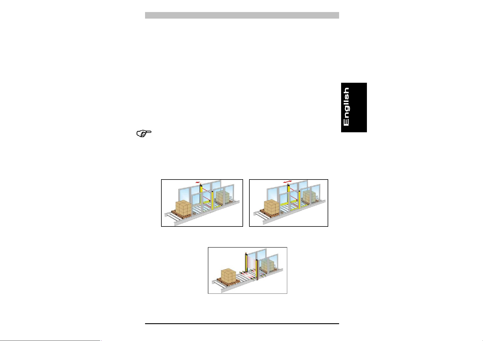
The following illustrations provide an overview of some of the main
application areas:
L-shape version with integral muting
sensors for muting in one direction
(leaving the danger zone)
T-shape version with integral muting
sensors for muting in two directions
Linear version with external muting sensors
6
Page 11

Operating Manual PSEN op4B Series
1.4 Safety information
For the proper, safe use of the safety light curtains, the following
guidelines must be followed:
• It must be possible to control the machine stop electrically.
• The control system must be able to stop the hazardous machine
movement immediately at any stage of the operating cycle.
• The safety light curtain and its respective electrical connections
must be installed by qualified personnel, in line with the guidelines
stated in the relevant chapters.
• The safety light curtain must be positioned in such a way that the
danger zone cannot be accessed without interrupting the beams
(see Chapter 2 “Installation”).
• Personnel working in the danger zone must be appropriately
trained with regard to the operation of the safety light curtain.
• The test/reset button must be positioned outside the danger zone
in such a way that operating personnel have a complete view of
the danger zone during all reset, test or override operations.
• The feedback loop monitoring function used to monitor the external
contactors will only be active if the corresponding wire is connected
to the device.
• The muting lamp that displays the activated muting function must
be visible from all sides of the work area.
• To ensure the correct operation of the muting switching devices,
follow the instructions provided in the installation manual.
• Before switching on the safety light curtain, make sure you comply
with the instructions regarding correct operation.
7
Page 12

PSEN op4B Series Operating Manual
2 INSTALLATION
2.1 Precautionary measures when selecting and installing the
device
• Make sure that the category guaranteed by the safety light curtain
(Type 4) matches the risk assessment for the machinery that is to
be monitored, as defined in the standard EN 954-1.
• The OSSD outputs on the safety light curtain must be used as
machine stop devices and not as command devices (the machine
must have its own START command).
• The dimensions of the smallest object to be detected must not be
less than the resolution level of the device.
• The environment in which the safety light curtain is installed must
comply with the technical details stated for the safety light curtain
in Chapter 10, “Technical details”.
• Avoid installing the device, particularly the receiver (RX), close to
intense and/or flashing light sources.
• Avoid strong electromagnetic interference as this can adversely
affect the proper operation of the device.
• Smoke, mist or dust within the operating environment can reduce
the range of the safety light curtain by up to 50%.
• Sudden temperature fluctuations beyond freezing point can cause
condensation to form on the surface of the lenses, adversely
affecting the proper operation of the safety light curtain.
• The activated muting function is displayed via an integral muting
lamp. Make sure that the intensity of the LED is appropriate and
that it is clearly visible, positioned close to the danger zone.
• Install and replace emitter and receiver only in pairs.
Emitter and receiver have the same serial number.
8
Page 13
Operating Manual PSEN op4B Series
• Make sure that the muting sensors are used appropriately and in
accordance with the following specifications. Avoid connections
that are inappropriate and unmonitorable, so that any accidental,
potentially hazardous activation can be prevented.
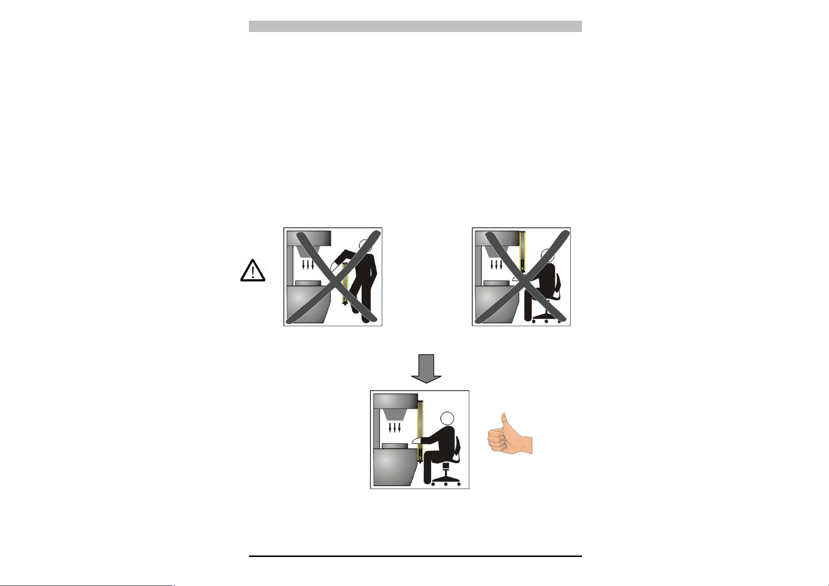
2.2 General information on positioning the device
For effective protection it is necessary to proceed very carefully when
positioning the device; in particular, the device must be installed in
such a way that the danger zone cannot be accessed without
interrupting the protected field.
To exclude the possibility of the machine being accessed from above
or below (Fig. 3a), it is necessary to install a safety light curtain that is
long enough to completely cover access to the danger zone (Fig. 3b).
NO
Fig. 3a
Fig. 3b
9
Page 14
PSEN op4B Series Operating Manual
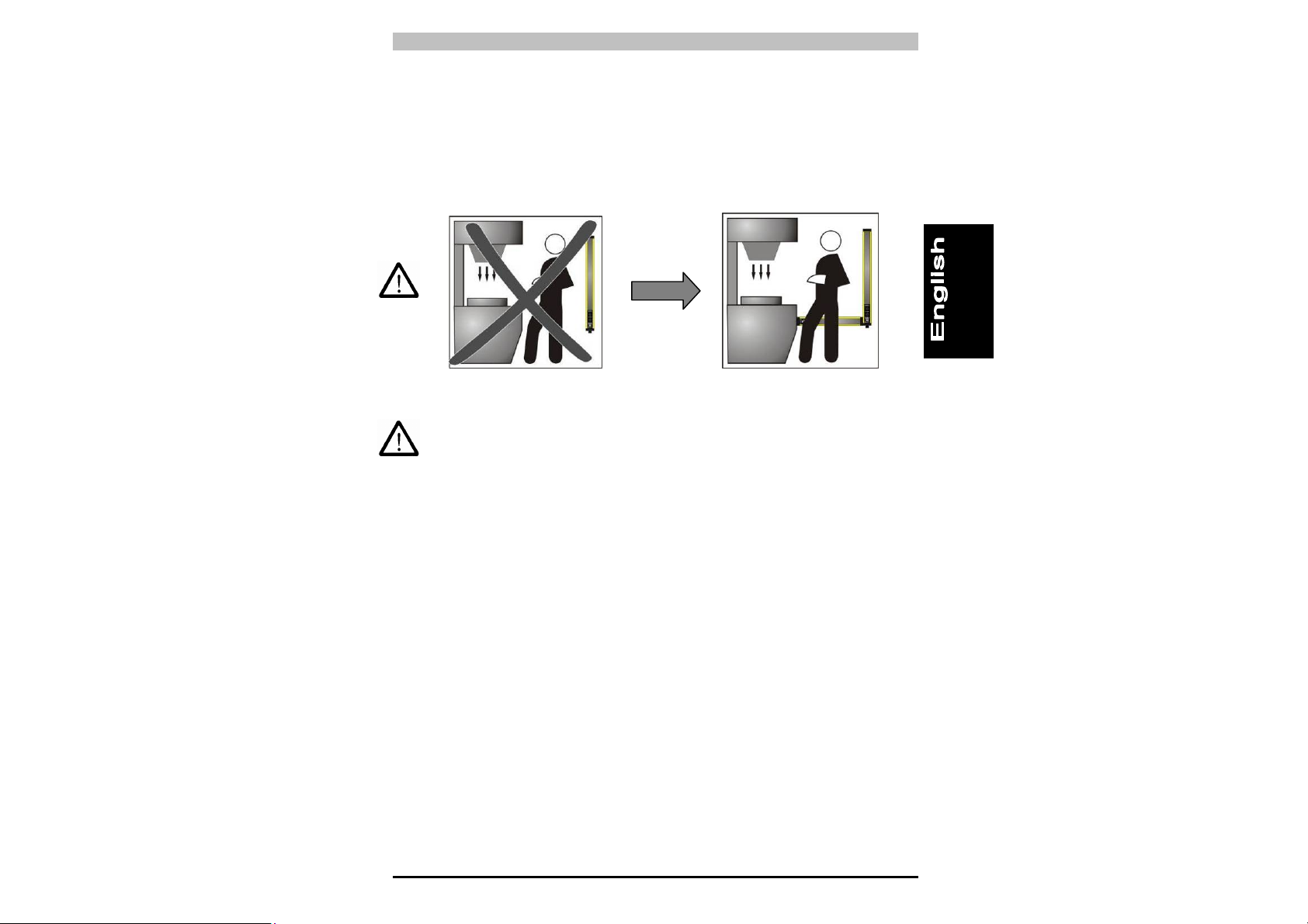
Also, under normal operating conditions, it must not be possible to
start the machine until the operator is outside the danger zone.
If it is impossible to install the safety light curtain in immediate
proximity to the danger zone, a second safety light curtain must be
installed and aligned horizontally, to exclude access from the side, as
shown in Fig. 4b.
Fig. 4a Fig. 4b
If the installation position of the safety light curtain still enables an
operator to access the danger zone without detection, an additional
mechanical barrier must be installed to prevent this.
10
Page 15
Operating Manual PSEN op4B Series
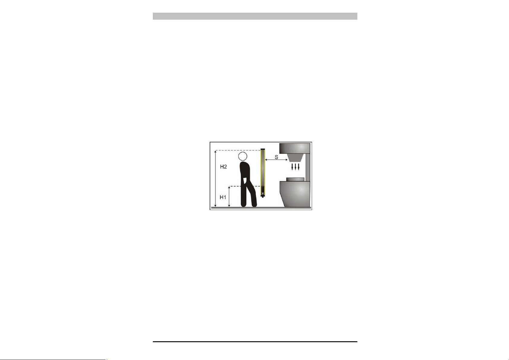
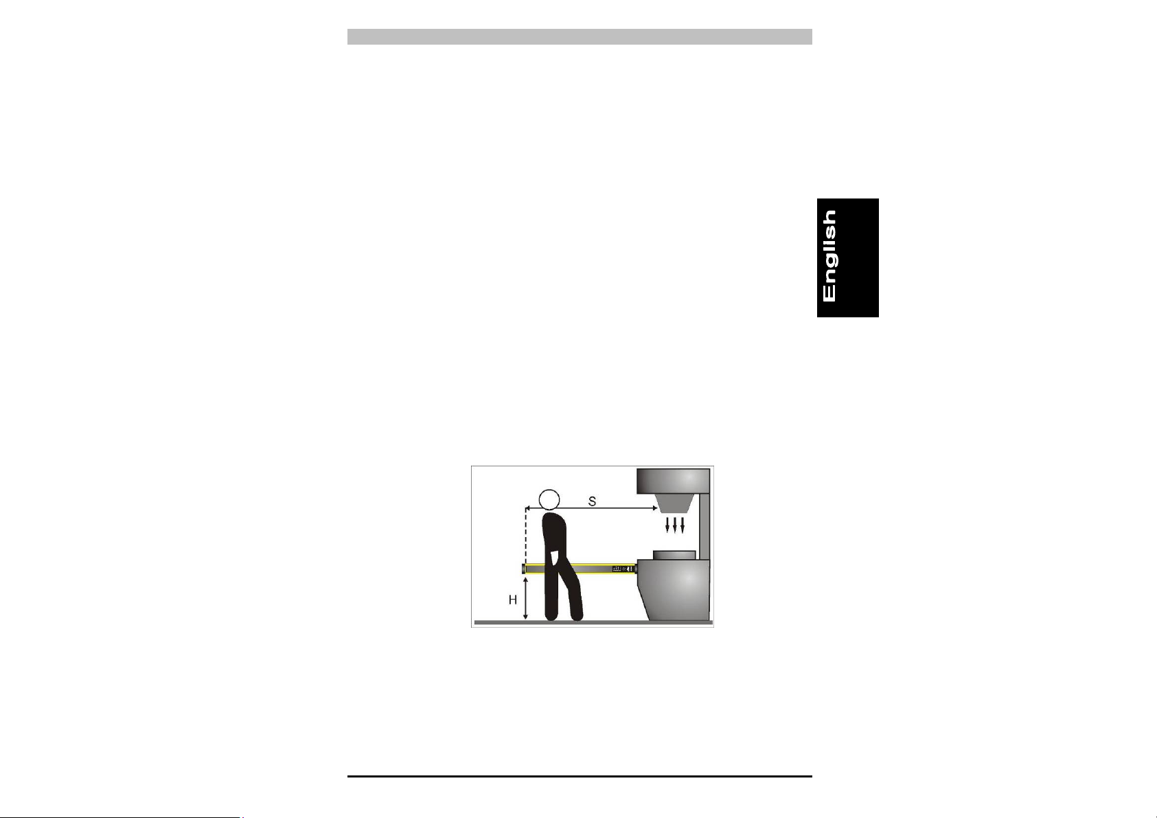
2.2.1 Minimum safety distance
The safety distance of the safety light curtain should be such that the
operator cannot reach the danger zone until the movement of the
hazardous machine part has come to a standstill (see Fig. 5).
According to the standards EN 999, 775 and 294, this distance
depends on four factors:
1 Reaction time of the safety light curtain (time it takes for the signal
at the OSSD output to switch from High to Low once the beams
have effectively been interrupted).
2 Machine's overrun time (time it takes for the machine to come to a
standstill once the reaction time of the safety light curtain has
elapsed).
3 Resolution of the safety light curtain.
4 Approach speed of the object requiring detection.
The formula for calculating the safety distance is as follows:
Fig. 5
S = K (t1 + t2) + C
where:
S = Minimum safety distance in mm between the protected field and
the danger zone
K = The speed at which the object requiring detection (body or parts
of the body) approaches the danger zone, in mm/s
t
= Reaction time of the safety light curtain in seconds (Ch. 10
1
“Technical details”).
t
= Machine’s overrun time in seconds
2
d = Resolution of the safety light curtain.
C = 850 mm for a safety light curtain with a resolution > 40mm
11
Page 16
PSEN op4B Series Operating Manual
Please note: The value of K is:
2000 mm/s, if the value calculated for S is ≤ 500 mm,
1600 mm/s, if the value calculated for S is > 500 mm.
If it is possible to access the danger zone from above and below (Fig.
5) and the devices used have a resolution of >40 mm, the upper beam
must be positioned at a height of 900 mm (H2), starting from the
reference plane (e.g. base of the machine), and the lower beam must
be positioned at a height of 300 mm (H1).
If the safety light curtain is to be installed horizontally
(Fig. 6), the distance between the danger zone and the furthest optical
beam must equal the value calculated using the following formula:
S = 1600 mm/s (t
+ t2) + 1200 – 0.4 H
1
where:
S = Minimum safety distance in mm between the protected field
and the danger zone
t
= Reaction time of the safety light curtain in seconds (Ch. 10
1
“Technical details”).
t
= Machine's overrun time in seconds
2
H = Height of the beams above the floor. This height must always
be less than 1000 mm.
Fig. 6
12
Page 17
Operating Manual PSEN op4B Series
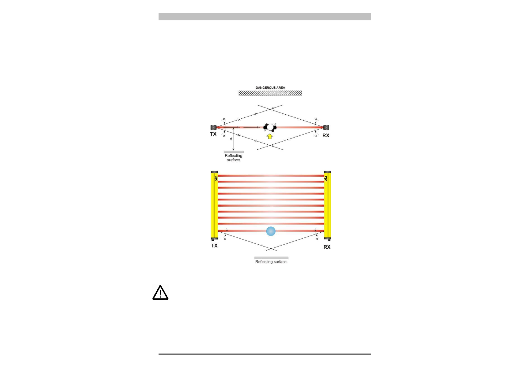
2.2.2 Minimum distance from reflective surfaces
Reflective surfaces close to the light beams emitted from the safety
device (whether above, below or to the side), may cause passive
reflections and adversely affect detection of the object within the
protected field (Fig. 7).
Fig. 7
Improper installation could mean that a protected field is interrupted
without detection, resulting in serious injury.
13
Page 18
PSEN op4B Series Operating Manual
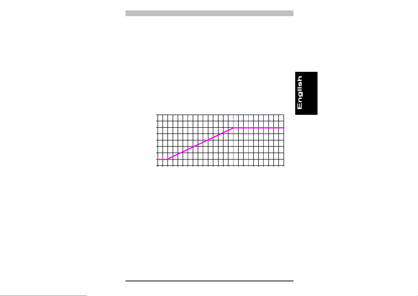
So, when installing the device close to reflective surfaces (metal walls,
floors, ceilings or workpieces), it is vital that the minimum distance in
relation to reflective surfaces is maintained, as shown in the diagram in
Fig. 8. This minimum distance depends on:
• The range between the emitter (TX) and receiver (RX)
• The maximum open angle of the light beams transmitted by the
emitter (TX):
5° for Type 4 ESPE (± 2.5° to light axis)
The values for the minimum distance in relation to the operating range
can be taken from the illustration in Fig. 8.
800
700
600
500
400
300
200
100
0
distanza superficie riflettente (mm)
reflecting surface distance (mm)
0 1 2 3 4 5 6 7 8 9 10111213141516171819202122232425
distanza operativa (m)
Operating distance (m)
Type 4
safety
light curtain
Fig. 8
14
Page 19

Operating Manual PSEN op4B Series
2.2.3 Installing several adjacent safety light curtains
If it is necessary to install several safety light curtains in adjacent
areas, you will need to ensure that the emitter (TX) on one device
cannot interfere with the receiver (RX) on another. To prevent this, the
devices will need to be installed conversely or must be separated via
screening (opaque surface).
Fig. 9 gives an example of an installation that could lead to
interference, plus two correct installations.
NO
YES
YES
Fig. 9
15
Page 20

PSEN op4B Series Operating Manual
2.2.4 Use of deviating mirrors
Deviating mirrors can be used to monitor danger zones where access
is possible from various sides.
Fig. 10 illustrates a potential solution for monitoring three different
access sides using two deviating mirrors positioned at an angle of 45°
to the safety light curtain.
Fig. 10
Please note the following precautions to take when using deviating
mirrors:
• The alignment of the emitter (TX) and receiver (RX) is particularly
critical when you use deviating mirrors; just a slight angular
displacement of the mirror is enough to lose the alignment. This
problem can be resolved by using a laser pointer, which is
available as an accessory.
• The minimum safety distance (S) must be maintained for each
section of the safety light curtain.
• Use of a deviating mirror reduces the effective operating range by
about 15%. If two or more deviating mirrors are used, the range will
be reduced still further (for more details please refer to the
technical specifications for the specific mirror).
• Never use more than three mirrors per device.
• Any dust or dirt on the mirror’s reflective surface will drastically
reduce the operating range.
16
Page 21

Operating Manual PSEN op4B Series
3 MECHANICAL ASSEMBLY
The emitter (TX) and receiver (RX)
must be assembled so that the
respective optical surfaces are aligned
in parallel and the connectors are
positioned on the same side. The
distance between the emitter (TX) and
receiver (RX) must be within the
operating range of the model you are
using (see type label or Chapter 9,
“Technical details”).
Align the devices precisely, following the guidelines given in Chapter 5,
“Alignment”.
Depending on the application, both units may either be screwed on
using the fixing bolts supplied or by using a rigid mounting bracket.
Fig.11
Fig. 12
Where there is particularly strong vibration, the muting sensor profiles
will also need to be screwed on using rigid mounting brackets (Fig.
13).
Fig. 13
17
Page 22

PSEN op4B Series Operating Manual
Rigid mounting brackets are suitable for installations that require no
large mechanical adjustments during alignment. Adjustable brackets
enable the units to be inclined by ± 5° and are available on request.
Where applications are subject to particularly strong vibration we
recommend the use of angle brackets with vibration dampers.
The drawing and table below indicate the recommended fixing points
in relation to the length of the safety light curtain.
MODEL L (mm) A (mm) B (mm)
PSEN op4B-T-2-050 642 342 150
PSEN op4B-T-3-080 942 542 200
PSEN op4B-L-2-050 642 342 150
PSEN op4B-L-3-080 942 542 200
PSEN op4B-S-2-050 642 342 150
PSEN op4B-S-3-080 942 542 200
18
Page 23

Operating Manual PSEN op4B Series
3.1 Installing the integral muting sensor profiles
with "L" and "T" shaped configuration
• Install the unit with the active muting
sensors on the receiver (RX) and the
unit with the reflectors on the emitter
(TX) of the safety light curtain.
• Use the fastening clip to attach the
muting sensor profile to the emitter
(TX) and receiver (RX) of the safety
light curtain. This ensures that the
muting sensor profiles are aligned
precisely and are perpendicular to the
light curtain units (Fig. 14a, Fig. 14b).
• With an "L" shape configuration:
Install the profile so that the object
can be detected before it reaches the
safety light curtain’s sensing area.
• Both muting sensor profiles must be
aligned in parallel. The muting
sensors are already aligned. Slight
adjustments may be made by moving
the fastening clip.
• For areas of heavy vibration
• You can choose where to position the
muting sensor profiles on the light
curtain units. (Typically 14 cm from
the bottom end of the light curtain unit).
Fig. 14a
Fig. 14b
Fig. 14c
19
Page 24

PSEN op4B Series Operating Manual
4 WIRING
4.1 Electrical connections
The electrical connections of the emitter (TX) and receiver (RX) are
made via M12 connectors, which are located on the bottom of both
units.
RECEIVER (RX):
8-pin M12 connector
OSSD1 PNP
OSSD2 PNP
0 V
+24 Vdc
1 = white = TEST/START
2 = brown = +24 Vdc
3 = green = OVERRIDE 1
4 = yellow = Feedback loop
5 = grey = OSSD1
6 = pink = OSSD2
7 = blue = 0V
8 = red = OVERRIDE 2
EMITTER (TX):
4-pin M12 connector
not connected
0 V
Feedback
loop
5
4
6
7
1
OVR1
3
2
8
+24 Vdc
OVR2
External N.C. contact
Externer N.O. contact
External N.O. contact
+24 Vdc
+24 Vdc
0 V
MUTING2
1 = brown = +24 Vdc
0 V
2
3
2 = white = MUTING 2
3 = blue = 0V
4 = black = MUTING 1
5 = grey = Not connected
1
4
+24 Vdc
not connected
MUTING1
+24 Vdc
2
3
1
4
not connected
1 = brown = +24 Vdc
2 = white = Not connected
3 = blue = 0 V
4 = black = Not connected
20
Page 25

Operating Manual PSEN op4B Series
4.2 Notes on wiring
To ensure the correct operation of the safety light curtain, please note
the following:
• Safe electrical isolation must be ensured for the external 24 V
supply. Failure to do so could result in electric shock. The supply
voltage must conform to EN 60950, 03/97, section 2.3, EN 60742,
9/95 or EN 50178, 10/97.
• Emitter and receiver must be connected using shielded cables
(accessories).
FIg. 14 shows how to connect the emitter and receiver properly.
Fig. 15
• At the point where the cable enters the cabinet, connect the screen
to the earth bar, without making a break in the cable. Use metal
cable clamps which cover the screen over a wide surface area.
• Under no circumstances should the connection cables come into
contact with or be laid in proximity to cables that generate strong
electromagnetic interference (e.g.: motor feeds, inverters etc.);
these could compromise the device’s ability to function.
• Multicore cables may not be used to connect the outputs of more
than one safety light curtain.
21
Page 26

PSEN op4B Series Operating Manual
• The TEST/RESET input must be connected to the supply voltage
on the ESPE via a button with a N/C contact. The test should be
performed manually (by pressing the button) at least once a day in
order to check the proper operation of the safety device.
• If the safety light curtain is started and there is no TEST/RESET
input connected to 24Vcc, it will switch to a monitoring condition, in
which the OSSD is not activated. In this case, set up the correct
connections and restart the system to restore operation under
normal safety conditions.
• The TEST/START button must be positioned in such a way that
the operator has a clear view of the protected area when reset, test
or override procedures are in progress (see Ch. 6 “Operating
mode”).
• The input for monitoring external contactors (feedback loop) must
be connected to 24 Vcc via a N/C contact before the safety light
curtain is switched on.
The monitoring function will not be activated if the input is not
connected properly when the safety light curtain is switched on. In
this case the safety light curtain will change to a fault condition.
• The device is already fitted with internal voltage and current
limitation. We would advise against the use of other external
components, even where this is permitted.
22
Page 27

Operating Manual PSEN op4B Series
• Earthing: If evaluation devices
are connected without safe
separation, the safety light
curtain must be operated in
protection class 1. In this case,
the emitter and receiver must
be labelled with the protective
earth symbol and must be
earthed via the fastening kit.
Both are supplied with the unit.
Assembling the fastening kit:
- Insert the slot nut (M4 x 0.7
mm tapped holes) into a
groove on the safety light
curtain.
- Screw the two threaded pins
(M4 x 14) into the external
tapped holes.
Fig. 16
- Fix the screws firmly in place
so that the cupped point on the threaded pin pierces the coating.
This way contact will be made with the metal housing.
- To prevent the threaded pin from working loose under heavy
vibration, attach two self-locking M4 nuts to the threaded pins.
Use a hexagonal wrench CH.7.
- Attach the earth lead to the middle tapped hole using the lock
washer (M4) and screw (M4).
23
Page 28

PSEN op4B Series Operating Manual
• Under no circumstances should safety contacts OSSD1 and
OSSD2 be wired in series or parallel; however, both may be used
separately.
If one of these two configurations should be used by mistake, the
safety light curtain will indicate an output malfunction (see Ch. 7
“Diagnostic functions”).
• Connect both OSSD outputs to the control element. If an OSSD
output is not connected to the control element, this will have a
negative effect on the safety level of the system in which the safety
light curtain is used.
Fig. 17
Fig. 19
24
Fig. 18
Fig. 20
Page 29

Operating Manual PSEN op4B Series
5 ALIGNMENT
The emitter (TX) and receiver (RX) must be aligned to ensure the
proper function of the device.
Perfect alignment is achieved when the optical axes of the first and last
beam from the emitter (TX) meet the optical axes of the corresponding
elements on the receiver (RX).
Two yellow LEDs on the receiver (RX), “HIGH ALIGN” and “LOW
ALIGN”, simplify the alignment process.
5.1 Alignment instructions
Once the mechanical assembly and the electrical connections have
been completed, the safety light curtain can be aligned as described
below:
• Disconnect the power supply to the safety light curtain.
• Press the TEST/START button and keep it held down (opens the
contact).
• Reconnect the power supply.
• You can now release the TEST/RESET button.
• On the emitter (TX), ensure that the green LED "POWER ON" and
the yellow LED "SAFE" are lit. This confirms that the transmitter is
operating correctly.
• Make sure that the status of the receiver is one of the following:
- BREAK Status: Green LED "POWER ON" is lit and LED
"SAFE/BREAK" lights up red (BREAK).
-> The safety light curtain is not aligned correctly.
- SAFE Status: Green LED "POWER ON" is lit and LED
"SAFE/BREAK" lights up green. The yellow LEDs “HIGH
ALIGN” and “LOW ALIGN” are lit.
-> The safety light curtain is aligned correctly.
25
Page 30

PSEN op4B Series Operating Manual
Follow the steps below to align the units:
• Hold the receiver (RX) steady and align the emitter (TX) so that the
yellow “LOW ALIGN” LED lights up, confirming that the first lower
beam has been aligned correctly.
• Rotate the emitter (TX) until the yellow “HIGH ALIGN” LED is also
lit. The “SAFE/BREAK” LED switches from red (BREAK) to green
(SAFE).
: Make sure that the “SAFE/BREAK” LED is constantly
NOTE
green.
• With a few small movements, define the area in which the
“SAFE/BREAK” LED is constantly green; do this first with one unit
and then with the other. Place both units in the centre of this area.
• Use the pins and/or mounting brackets to firmly secure both the
units.
• Disconnect the power supply to the safety light curtain.
• Reconnect the power supply.
• Make sure that the green “POWER ON” LED on the receiver (RX)
is lit (light beams are clear, “SAFE” operating status) and that this
switches to red if just a single beam is interrupted (detected object,
“BREAK” operating status).
• Perform this test using a cylindrical “test rod”, the diameter of
which should correspond to the resolution of the device (14 mm, 20
mm, 30 mm or 35 mm). The test rod is available as an accessory.
: If you pass the test rod from top to bottom along the
NOTE
length of the whole sensing area, at any distance from
either unit, the “SAFE/BREAK” LED must be constantly
red. We recommend that you perform this test daily.
26
Page 31

Operating Manual PSEN op4B Series
5.2 Aligning the muting sensors
• Once the safety light curtain has been aligned and the muting
sensor profiles have been installed and wired, you will need to
check that the sensors on the profiles are aligned correctly. Slight
adjustments may be made by moving the fastening clip.
Fig. 21
27
Page 32

PSEN op4B Series Operating Manual
6 FUNCTIONS
6.1 Selecting the operating mode via DIP switches
On the front of the receiver (RX) there is a cover flap (Fig. 22), which is
easy to open using a screwdriver and enables access to a row of DIP
switches for the following configurations:
- Muting function/muting timeout
- Feedback loop monitoring function
- Manual/automatic reset
The device will not accept configuration
changes during normal operation. A
configuration change will only take effect
once the device is reset.
Particular care should therefore be taken
when setting the DIP switches.
DIP-sw FUNCTION ON OFF
1 Muting timeout 10 min Infinite
2 Muting
Feedback loop
3
4 Restart Automatic Manual
monitoring
T-shape
configuration, linear
configuration
Deactivated Activated
6.2 Standard configuration
DIP SWITCHES
Abb. 22
L-shape
configuration
The device is supplied with the following standard configuration:
- Muting timeout: 10 min
- Muting: In T shape configuration
- Feedback loop monitoring function: Deactivated
- Restart: Automatic
NOTE: The muting function can only be activated if muting inputs
1 and 2 and the muting lamps are connected correctly.
Detailed information on this function can be found in
chapters 6.3 and 6.4.
28
Page 33

Operating Manual PSEN op4B Series
6.3 Restart
If the beams between the emitter (TX) and receiver (RX) are
interrupted by an opaque object, the OSSD outputs will switch and the
safety contacts will open (“BREAK” operating status).
There are two different ways to restart normal mode (“SAFE” operating
status):
• Automatic reset: After the protected field has been interrupted, the
safety light curtain returns to its normal mode as soon as the
detected object has been removed from the protected field.
• Manual reset: After the protected field has been interrupted, the
safety light curtain does not return to its normal mode until the
object has been removed from the protected field and the restart
button (TEST/RESET button) has been operated for at least 0.5 s.
Timing diagram for manual reset (local or external activation of restart
function)
29
Page 34

PSEN op4B Series Operating Manual
Fig. 23 shows the two operating modes:
BREAK
Automatic
reset
SAFE
TX
BREAK
TEST/RESET
button
SAFE
Normal mode
Beams clear
SAFE
RX RX RX
TX
OSSD OFF OSSD ON
Beams
interrupted
TX
BREAK
Beams clear
Manual
reset
OSSD ON
OSSD OFF
OSSD OFF
OSSD ON
Fig. 23
Automatic or manual reset can be selected via the DIP switches on the
receiver (RX).
• Automatic reset: Set position 4 on both DIP switches to ON
• Manual reset: Set position 4 on both DIP switches to OFF
ON
1 2 3 4
ON
1 2 3 4
NOTE: DIP switches that are not used for this function are shown
in grey in the diagram.
30
Page 35

Operating Manual PSEN op4B Series
6.4 Test function
The test function can be used to carry out a function test on the safety
light curtain. The test function is activated via the input (TEST/RESET)
on the receiver (RX). The function is activated when the TEST/RESET
button has been operated for at least 0.5 s.
AUTOMATIC RESET
MANUAL RESET
31
Page 36

PSEN op4B Series Operating Manual
6.5 Reset function
The safety light curtain has a reset function which is used in the case
of internal errors. To cancel the reset lock and restore the normal
operating status, press the TEST/RESET button for at least 5 s.
Carry out the reset function in the following cases:
• Irregular output function
• Irregular optical function
• Irregular operation of the feedback loop monitoring function
• Irregular muting display function
Timing diagram for the reset function
32
Page 37

Operating Manual PSEN op4B Series
6.6 Feedback loop monitoring function
The safety light curtain has a feedback loop for
monitoring the externally connected contactors. The
opening/closing of the electrical contacts is
monitored by a N/C contact.
Activate the feedback loop monitoring function:
- Select the relevant DIP switch
- Connect the feedback loop input to a 24 Vcc N/C
contact on the device to be monitored.
The diagram on the right shows the correct layout of the DIP
switches (DIP switch 3 OFF) to activate the feedback loop.
ON
1 2 3 4
ON
1 2 3 4
33
Page 38

PSEN op4B Series Operating Manual
This function monitors the switching of the N/C contacts when the
OSSD output status changes.
TC ≤ 350 ms Time after which the feedback loop contacts open once
the OSSD outputs switch from OFF-ON
T
≤ 100 ms Time after which the feedback loop contacts close once
0
the OSSD outputs switch from ON-OFF
Use control elements whose dynamics are compatible with the time
constraints stated above.
If inappropriate devices are used, the safety light curtain may switch to
a fault condition.
We recommend that this function is checked regularly.
34
Page 39

Operating Manual PSEN op4B Series
6.7 Muting function
The muting function enables the safety light curtain to be suspended
temporarily while material is transported through the protected field
(Fig. 24).
• "L" shape configuration: is suitable for applications in which an
object leaves the danger zone in one direction.
• "T" shape configuration: is suitable for applications in which an
object moves in two directions.
• Linear models: Are suitable for applications on which the sensors
are intended to be positioned individually. A plug connector
enables the muting sensors to be connected simply.
L-shape version with integral muting
sensors for muting in one direction
(leaving the danger zone)
Linear version with external muting sensors
T-shape version with integral muting
sensors for muting in two directions
Fig. 24
35
Page 40

PSEN op4B Series Operating Manual
To comply with current regulations the safety device has two inputs
(muting 1 and muting 2) for activating the muting function.
For example, the muting function can be used when objects need to
pass through the protected field, but operating personnel still require
protection.
Muting duration:
• Muting timeout 10 min.: Set position 1 on both DIP switches to ON
• Muting timeout infinite: Set position 1 on both DIP switches to OFF
Muting configuration:
• T-shape configuration or linear configuration: Set position 2 on
both DIP switches to ON
• L-shape configuration: Set position 2 on both DIP switches to OFF
When using the muting function, please note the following:
• The muting function represents a forced situation for the whole
system and as such should be applied with due care.
• The muting sensors must be connected and positioned properly,
so that personnel are not exposed to unwanted muting activations
or hazardous situations.
• Muting cannot be activated if the protected field is interrupted
(“SAFE” LED lights up red).
• When you have different conveyor speeds in muting mode, you will
need to consider the effect this will have on the overall duration of
the muting process.
• The receiver has a muting lamp which displays the
status of the muting function (Fig. X). If the muting
lamp is defective, activating muting or override will
cause the safety contacts to open and the plant will
be disabled due to a muting lamp malfunction
(see Chapter 8.2 “Error messages and diagnostics”).
The muting lamp must be clearly visible from all
sides of the work area.
Fig. 25
36
Page 41

Operating Manual PSEN op4B Series
• The vehicle should be designed to make it impossible for
people to ride on it.
• Limit the size of the entry area by applying appropriate safety
measures. People must not be permitted to enter the danger
area during the muting phase.
• Make sure that you select the correct muting configuration
(DIP switch position 2). The "OFF" position is provided
exclusively for safety light curtains with an L-shape
configuration. Any discrepancy in the configuration may
cause the muting function to operate incorrectly and reduce
the level of safety.
• In each case, the muting sensors must be positioned so that
muting cannot be activated by somebody passing through the
protected field.
• Muting can be activated in 2 ways:
- Activation of both muting inputs simultaneously (not in the case
of L-shaped muting)
- Activation of muting input 1 and then muting input 2, or viceversa.
• Muting cannot be activated if the protected field is interrupted
(“SAFE” LED lights up red).
• An "infinite" muting timeout does not conform to the
specifications of EN 61496-1. If the muting timeout has been
set to "infinity", the muting sensors must be tested at
intervals that are compatible with the process. This can be
done by shutting down the plant or by idling the muting
channel, for example.
• If the muting timeout is set to “infinity”, the level of safety that
can be achieved may be reduced.
37
Page 42

PSEN op4B Series Operating Manual
Fig. 26 shows an example of a muting function application.
Lamp flashes when
muting is active
OSSD ON
SAFE
MUTING OFF
SAFE
OSSD ON
Fig. 26
MUTING OFFMUTING ON
SAFE
OSSD ON
38
Page 43

Operating Manual PSEN op4B Series
Timing diagram of the muting function for configurations with 2 sensors
(L-shaped version or linear version with 2 intersecting beams)
Timing diagram of the muting function for configurations with 4 sensors
(T-shaped version or linear version with 4 sensors)
39
Page 44

PSEN op4B Series Operating Manual
A
A
6.7.1 Installing the muting sensors on PSEN op4B-S models
As the package passes through, the safety function is temporarily
suspended via the muting sensors. The outputs on these sensors are
connected to the muting inputs MUTING 1 and MUTING 2 on the
safety light curtain receiver (RX).
The contacts for these sensors are monitored via the receiver (RX).
Optoelectronic, mechanical, proximity sensors etc. can be used as
muting sensors, using a closed contact when the object requiring
detection is present.
The following examples illustrate the application of the muting function:
- Application with four optoelectronic sensors: Configured with
parallel light axes
This solution is suitable for applications in which the object can be
moved in two directions.
For correct operation set position 2 on the DIP switch to ON.
2B2
PSEN
d1 d1
D
L
v
1B1
Connecting the muting sensors:
V4
CONTACT A1
CONTACT A2
CONTACT B1
CONTACT B2
Receiver connector
Pin 3
MUTING 1
Pin 7
MUTING 2
• The distance between B2 and A2 or B1 and A1 should be as long
as possible, but distance D between A2 and A1 must be less than
the object size L
• A2 and B1 must be positioned as close as possible in front
of/behind the safety light curtain.
40
Page 45

Operating Manual PSEN op4B Series
• The maximum possible distance of d1 between B2 and A2 or B1
and A1, depends on the object’s approach speed:
d
d
• Muting sensors A1 and B1 or A2 and B2 must be operated within
4 s.
[cm]= v [m/s] * t
1max.
[cm] ≥ 0.1 cm
1min.
[s] * 100
Gl
41
Page 46

PSEN op4B Series Operating Manual
A
A
- Application with two optoelectronic sensors: configured with
parallel intersecting beams
This solution is suitable for applications in which the object can only be
moved in one direction.
For correct operation set position 2 on the DIP switch to ON.
Danger zone
B
PSEN
D
L
Contact from
V=const.
Connecting the muting sensors:
24 Vcc
4-pin M12 connector
PSEN receiver
Pin 2
MUTING 1
Pin 4
MUTING 2
Contact from B
• The beams must always intersect within the danger area.
• Muting sensors A and B must be operated within 4 s.
42
Page 47

Operating Manual PSEN op4B Series
A
6.7.2 Installing the muting sensors on PSEN opB-L models
The integrated muting function in an L-shaped configuration enables
the muting sensors to be easily installed and is suitable for applications
in which the object is to travel out of the danger zone.
For correct operation set position 2 on the DIP switch to OFF.
Contact from A
V=const.
Contact von B
PSEN
L
B
D
D
Moff
• The distance d1 between A and B is 16.5 cm
• Muting sensors A and B must be operated consecutively within
4 s.
Connecting the muting sensors:
24 Vcc
4-pin M12 connector
PSEN receiver
Pin 2
MUTING 1
Pin 4
MUTING 2
• Once muting sensor A has been cleared, the muting function is
held for another 4 s. After this time the muting function switches off
and the safety light curtain returns to normal mode.
• You should also secure the light curtain area outside the danger
zone, e.g. using a safety fence, so that it is impossible for anyone
to access the danger zone during the 4 s in which the muting
function is held.
43
Page 48

PSEN op4B Series Operating Manual
A
A
V
6.7.3 Installing the muting sensors on PSEN opB-T models
The integrated muting function in a T-shaped configuration enables the
muting sensors to be easily installed and is suitable for applications in
which the object is moved in two directions.
For correct operation set position 2 on the DIP switch to ON.
Contact from A1
L
=cons
Contact from A2
2B2
PSEN
D D
d
1B1
Contact from B1
Contact from B2
• The distance d1 between A1 and B1 or A2 and B2 is 16.5 cm.
• The distance D between A1 and A2 or B1 and B2 is 34.5 cm.
• Muting sensors A and B must be operated consecutively within
4 s.
Connecting the muting sensors:
24 Vcc
4-pin M12 connector
PSEN receive r
Pin 2
MUTING 1
Pin 4
MUTING 2
44
Page 49

Operating Manual PSEN op4B Series
6.8 Override function
This function can be used to activate the muting function when the
plant needs to be started even though there is an object within the
protected field. The aim is to clear the danger zone of any material that
may have accumulated due to a fault in the operating cycle.
Example:
There is a pallet within the protected field and the conveyor cannot be
switched on because the safety light curtain will not enable its outputs
(one or more of the beams are interrupted), so the accumulated
material cannot be transported away. Activating the override function
enables this type of intervention.
Activate the override function:
• With manual reset: When the protected field has been interrupted,
the override function cannot be activated until the TEST/RESET
button has been pressed.
• The override function is activated via the local input (OVR1 and
OVR2) on the receiver (RX). To do this, connect a pushbutton with
N/O contacts to OVR1 and 24 Vcc and PVR2 and 0 Vcc.
• The override function is active when both N/O contacts close
simultaneously (simultaneity between the contacts max. 400 ms).
• Press the OVERRIDE button and keep it held down until all the
accumulated material has been cleared away.
While the override function is active the muting lamp will flash to signal
the suspension of the safety light curtain.
The maximum duration of the override function is 120 s. After this time
the override function switches off, even if the “OVERRIDE” button is
operated. If the button is released before this time has elapsed, the
override function switches off immediately.
45
Page 50

PSEN op4B Series Operating Manual
The override function is ended automatically when:
• There are no muting sensors active
• Muting timeout is exceeded
• At least one override input is deactivated
Timing diagram: Override function
24 Vcc
OVR1
0 V
24 Vcc
0 V
OVR2
Override function
ON
OFF
0 ≤ ΔT < 400ms
46
Page 51

Operating Manual PSEN op4B Series
7 DIAGNOSTICS
7.1 Function indicators
4 LEDs on the receiver (RX) and 2 LEDs on the emitter (TX) provide
the user with information about the operating status of the safety light
curtain.
Fig. 27
The key to the LEDs on the receiver (RX) depends on the operating
mode.
47
Page 52

PSEN op4B Series Operating Manual
7.2 Error messages and diagnostics
The LEDs that display the function can also be used by operators to
evaluate the main causes of an error.
RECEIVER:
Defect Cause Checks and remedy
Flashing red
Flashing yellow
Flashing yellow
Constant green
Flashing red
Off
Flashing yellow
Constant green
Off
Flashing yellow
Flashing yellow
Constant green
Constant red
Flashing yellow
Off
Constant green
Constant red
Flashing yellow
Flashing yellow
Constant green
Off
Off
Flashing yellow
Constant green
Malfunction of the
outputs
Malfunction of the
external control unit
(function of the
feedback loop
monitoring test)
Malfunction of the
microprocessor
Override function can
be called up
Irregular override
function
Optical fault
- Check the output connections.
- Check that the load is compatible
with the specifications given in the
TECHNICAL DETAILS table (Ch.
9).
- Check the feedback loop
monitoring connections
- Check the compatibility of the
external unit and the test times for
feedback loop monitoring
- Switch the unit off and then on
again; if the problem persists,
change the external unit.
- Check the correct position of the
DIP switches.
- Switch the device off and then on
again; if the problem persists,
contact PILZ.
- The display is indicating that there
is no defect
- Activate the override function in
order to remove the material from
the area of the protected field.
- Check the contacts for the
override function. If the fault
persists, contact Pilz.
- Check the alignment of emitter
and receiver
- Switch the device off and then on
again; if the fault persists, contact
PILZ.
48
Page 53

Operating Manual PSEN op4B Series
EMITTER:
Defect Cause Checks and remedy
Flashing green
Flashing yellow
Flashing yellow
Constant green
Off
Off
Off
Off
Off
Off
Off
Constant green
Irregular function of the
integral muting display
Supply voltage error - Check the supply voltage
The supply voltage is
outside the permitted
range
Malfunction of the main
microprocessor
- Switch the device off and then
on again; if the fault persists,
contact PILZ.
- If the fault persists, contact Pilz.
- Check the supply voltage
- If the fault persists, contact Pilz.
Defect Cause Checks and remedy
Flashing yellow
Constant green
Off
Off
Off
Constant green
General irregularity on
the emitter
Supply voltage error - Check the supply voltage
The supply voltage is
outside the permitted
range
Malfunction of the main
microprocessor
- Check the supply voltage; if the
display does not go out, contact
Pilz.
- If the fault persists, contact Pilz.
- Check the supply voltage
- If the fault persists, contact Pilz.
49
Page 54

PSEN op4B Series Operating Manual
8 REGULAR CHECKS AND MAINTENANCE
Qualified personnel must carry out the following checks regularly.
Ensure that:
• The “SAFE/BREAK” LED is constantly red when you pass the test
rod from top to bottom along the length of the whole sensing area,
at any distance from either unit.
• The safety light curtain switches to an OFF state when the
test/reset button is operated (“SAFE/BREAK” LED lights up red OSSD outputs open - monitored machine switches to a safe
condition).
• The reaction time at a machine stop, incl. the reaction time of the
safety light curtain and the machine overrun time, is within the
limits defined through the calculation of the safety distance (see
Chapter 2 “Installation”).
• The minimum safety distance between the danger zone and the
protected field is in accordance with the details stated in Chapter 2
“Installation”.
• Nobody can access and remain in the danger zone between the
safety light curtains and the hazardous machine parts.
• The danger zone cannot be accessed from any unprotected area.
• There is no visible damage to the safety light curtain and/or the
external electrical connections.
We recommend a yearly inspection.
50
Page 55

Operating Manual PSEN op4B Series
8.1 Maintenance
Safety light curtains require no particular maintenance, except for
cleaning the optical covers. Moist cotton cloths should be used for
cleaning.
We recommend that you do not use:
• Alcohol or solvents,
• Cloths made of wool or synthetic material
8.2 General information and useful data
Safety devices are only beneficial if they are installed correctly, in
accordance with the regulations.
If you find that you do not have the necessary expertise to install the
safety devices correctly, please contact our technical support.
Electronic fuses protect the devices against short circuit. Once these
have reacted you will need to disconnect the power supply for at least
20 seconds and rectify the short circuit. When you reconnect the
power supply the fuses will have reset and the safety light curtain can
automatically resume normal operation.
Faults that result in a power supply failure may cause the outputs to
open temporarily, but do not adversely affect the safe operation of the
safety light curtain.
Install and replace emitter and receiver only in pairs.
Emitter and receiver have the same serial number.
Guideline for repair: Always send both emitter and receiver for repair.
(During repair, both units are programmed with the current software
version).
51
Page 56

PSEN op4B Series Operating Manual
r
9 TECHNICAL DETAILS
Supply voltage
Internal capacity 23 nF (Tx) / 120 nF (Rx)
Current consumption, emitter (TX) Max. 30 mA / 0.9 W
Current consumption, receiver (RX) Max. 75 mA (without load) / 2.2 W
Current consumption, muting senso
profiles
Outputs:
Output current: Max. 0.5 A / each output
Output voltage ON - min.: Vdd –1 V
Output voltage OFF - max. 0.2 V
Capacitive load (pure) Max. 65 nF at 25°C
Resistance load (pure)
Leakage current < 1 mA
Reaction time 14 ms
Emitter, wavelength Infra-red (880 nm)
Resolution 415 mm (2 optics)
Operating range 0.5…3 m (PSEN op4B-T/L), 0.5…25 m (PSEN op4B-S)
Category Type 4
Timeout points Muting: 10 min / infinity
Operating temperature -10 … +55 °C
Storage temperature -25 … +70 °C
Humidity 15 ... 95 % (non-condensing)
Protection class Class 1 (see section 4.2 "Wiring guidelines", "Earthing"
Protection type IP65 (EN 60529)
Ambient brightness IEC-61496-2
Vibration Amplitude 0.35 mm, frequency 10 ... 55 Hz, 20 sweeps
Shock resistance 16 ms (10 G) 1,000 shocks for all axes
Reference standards IEC 61496-1; IEC 61496-2
Housing material Varnished aluminium (yellow RAL 1003)
Material of upper and lower cover PC MAKROLON
Material for optics PMMA
Connections 4-pin M12 connector on TX
Cable runs
Supply
Weight Max. 1.2 Kg / m per unit
* If a longer cable is used, you will need to make sure that the relevant specifications are met.
24 VDC ±20% (SELV/PELV)
Max. 35 mA / 1 W (when sensors switched to 'OFF')
2 PNP
Max. short circuit stability: 1.4 A at 55°C
min: 1.1A at -10°C
Min. 56Ω at 24 Vcc
515 mm (3 optics)
Override: 2 min
section)
for all axes; 1 octave/min., (EN 60068-2-6)
(EN 60068-2-29)
8-pin M12 connector on RX
Max. 50 m*
52
Page 57

Operating Manual PSEN op4B Series
10 LIST OF AVAILABLE MODELS
PSEN op4B-T-2-050
PSEN op4B-T-3-080
PSEN op4B-L-2-050
PSEN op4B-L-3-080
PSEN op4B-S-2-050
PSEN op4B-S-3-080
MODEL
Length of
sensing
Distance
area
515 500 2 515 14 0.5…3 m
415 400 3 415 14 0.5…3 m
515 500 2 515 14 0.5…3 m
415 400 3 415 14 0.5…3 m
515 500 2 515 14 0.5…25 m
415 400 3 415 14 0.5…25 m
No. of
beams
Resolution
mm
Reaction
time (ms)
Operating
range (m)
11 OVERALL DIMENSIONS
All dimensions are stated in mm.
35
35
40
691 373
MODEL A (mm) B (mm) C (mm)
PSEN op4B-T-2-050 120…260 653 690
PSEN op4B-T-3-080 120…260 953 990
PSEN op4B-L-2-050 120…260 653 690
PSEN op4B-L-3-080 120…260 953 990
PSEN op4B-S-2-050
PSEN op4B-S-3-080
120…260
120…260
53
C
B
A
653 690
953 990
Page 58

PSEN op4B Series Operating Manual
12 ACCESSORIES
12.1 Mounting bracket
MODEL DESCRIPTION
Bracket kit PSEN 4 (1) Bracket (4-part kit)
Bracket kit PSEN 4 anti vibr. (2) Anti-vibration brackets (4-part kit)
Bracket kit PSEN 4 adjust. (3) Adjustable brackets (4-part kit)
Mounting type A Mounting type B
.nim 2.14
.278
3am .45.x
Standard mounting bracket (1)
m 7.xa9
2am .05.x
°5±
°5±
7m 5.xa4.
Standard mounting bracket + adjustable bracket (1 + 3)
.278
5.25
2.65
.xam 75
.65 2
021.
.162
2
502Ø
73.4
52Ø
0
2
Standard mounting bracket + anti-vibration bracket (1 +2)
m857.xa9
°5±
m 9.27.xa
Ø52
02
Standard bracket+adjustable bracket+anti-vibration bracket (1 + 2 + 3)
8.97.xam
±°5
.m xa
75
6.52
5
202Ø
54
Page 59

Operating Manual PSEN op4B Series
12.2 Deviating mirror
MODEL DESCRIPTION
Mirror 550mm Deviating mirror H= 550 mm
Mirror 700mm Deviating mirror H= 700 mm
Mirror 900mm Deviating mirror H= 900 mm
Mirror 1000mm Deviating mirror H= 1000 mm
Mirror 1270mm Deviating mirror H= 1270 mm
Mirror 1600mm Deviating mirror H= 1600 mm
Mirror 1800mm Deviating mirror H= 1800 mm
L1 (mm) L2 (mm)
554 384
704 534
904 734
1004 834
1264 1094
1604 1434
1804 1634
55
Page 60

PSEN op4B Series Operating Manual
12.3 Floor brackets
MODEL DESCRIPTION
Stand 1000mm Floor brackets H= 1000 mm
Stand 1200mm Floor brackets H= 1200 mm
Stand 1500mm Floor brackets H= 1500 mm
Stand 1800mm Floor brackets H= 1800 mm
L (mm) X (mm)
1000 30x30
1200 30x30
1500 45x45
1800 45x45
56
Page 61

Operating Manual PSEN op4B Series
12.4 Laser pointer
The laser pointer in the PSEN op2/4 series is a valuable guide when
aligning and installing the safety light curtains. The pointer can be
moved along the light curtain profile to check the overall alignment of
the safety light curtain.
MODEL DESCRIPTION
LaserPointer for PSEN 4/2 Laser pointer for alignment
Fig. 28
57
Page 62

PSEN op4B Series Operating Manual
12.5 Connection box
The connection box PSEN iop1 makes it easier to connect and operate
the safety light curtains.
Features:
• Key switch for the override function
• TEST/RESET button for activating the test, restart and reset
function
• Connections for:
- Receiver (RX)
- Emitter (TX)
- Supply voltage
- Relay outputs
- External control unit
MODEL DESCRIPTION
PSEN iop1 Connection box
Fig. 29
58
 Loading...