

Page 1
Installation and Operating Instructions
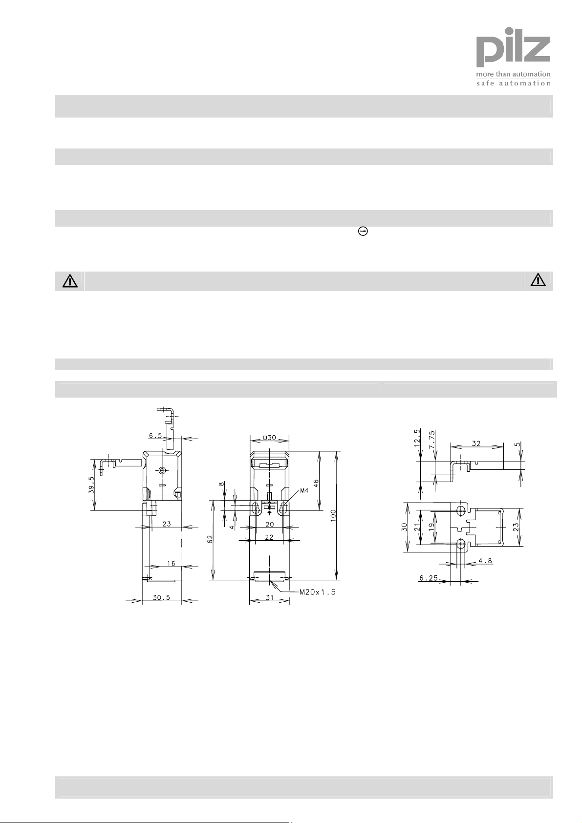
Plastic encased safety interlocking switch
Type
Intended use
The plastic encased safety switches PSEN me4 with separate actuator are suitable for the mounting on safety
guards. They are designated to trigger switching operations in control circuits.
Function
If the safety guard is opened the contact(s) with forced disconnection will break the safety control circuit (safety
contacts get opened).
Improper installation or manipulation of the safety switch renders the personal protection function useless and can
cause serious injury or accidental death.
In order to maintain the maximum level of safety, always order and use actuators together with the correct safety
switches.
PSEN me4
Dimensions [mm] Actuator
Safety instructions
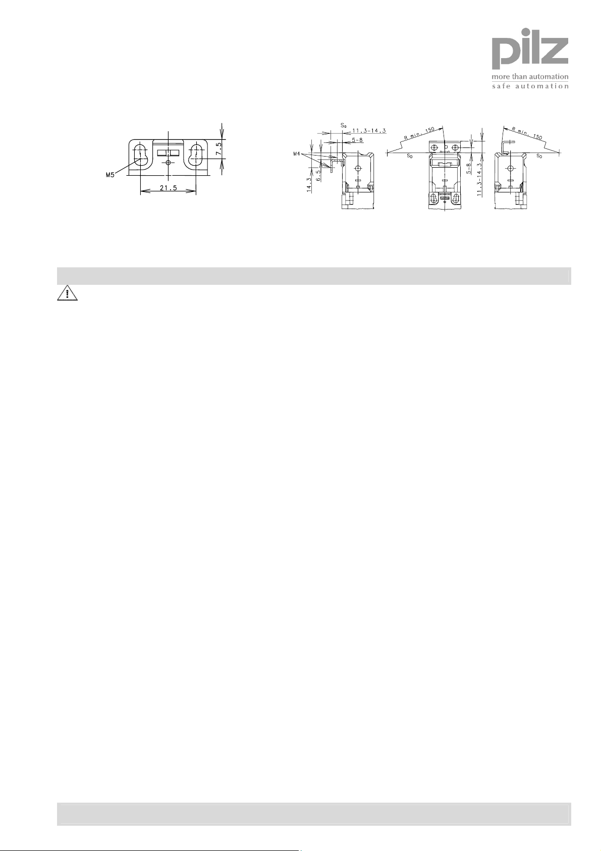
PSEN me4AS
Pilz GmbH & Co. KG, Sichere Automation, Felix-Wankel-Straße 2, D-73760 Ostfildern, Deutschland
Phone: +49 711 3409-0, Fax: +49 711 3409-133, E-Mail: techsupport@pilz.de, www.pilz.com
Date of issue: 31.01.2005 / Page 1 of 5
Document: 0800000424_en / Version: 1
Template : 0850174292 Orig. 2
Page 2
Installation and Operating Instructions
Fixed positioning for safety applications (M5)
Minimum radii reference to a point of rotation
on enclosure top edge S
0
Installation
Installation by trained and qualified personnel only!
To mount the switch gear 2 screws M5 shall be used.
Actuator PSEN me4AS:
The user shall make sure that the actuator is form-fit mounted. The actuator mounting should not be solvable with
simple tools. For a tamperproof mounting use one-way screws of M 4X8 size.
The switch and the actuator shall be aligned during installation in such a way that even after multiple actuations of
the safety guard no lateral forces affect the actuator head.
The mounting position is any desired but shall support inspection and replacement if necessary by qualified
personnel. Choose such a mounting position that no foreign parts seep into the opening of the actuating device.
The rated degree of protection (IP-Code) of the switch applies only with closed cover lid and when an at least
evenly matched cable gland with adequate cable is used.
The switches shall not be used as mechanical end stop.
Pilz GmbH & Co. KG, Sichere Automation, Felix-Wankel-Straße 2, D-73760 Ostfildern, Deutschland
Phone: +49 711 3409-0, Fax: +49 711 3409-133, E-Mail: techsupport@pilz.de, www.pilz.com
Date of issue: 31.01.2005 / Page 2 of 5
Document: 0800000424_en / Version: 1
Template : 0850174292 Orig. 2
Page 3

Installation and Operating Instructions
The safety switch shall not be used as
mechanical end stop!
Position of
mechanical stop adjustable
(not supplied with
safety switch)
4 different directions of actuation by turning the cap
from 0° to 270°:
1. draw clasp out
2. turn actuator head
3. press-on clasp
Cover for unused entry
Actuating forces (Extraction force):
Standard = 10 N
PSEN me4.01, PSEN me4.11,
PSEN me4.21 = 50 N
Connecting the cable:
Connection type:
2 or 4 screw connectors M3,5 or
6 screw connectors M3
Conductor cross section:
singl e core 0,5-1,5 mm²/litz wire with
connector sleeve 0,5-1, 5 mm²
Electrical connection
The electrical connection shall only be carried out by trained and qualified personnel!
The electrical contacts of switches PSEN me4, PSEN me4.01, PSEN me4.1 and PSEN me4.11 feature 4 screw
terminals M3,5.
Tightening torque M = 0,8 Nm.
The electrical contacts of switches PSEN me4.2 and PSEN me4.21 feature 6 screw terminals M3.
Tightening torque M = 0,6 Nm.
The connection requires a stranded wire with ferrule or a solid wire with a cross section of 0,5 – 1,5 mm².
For safety circuits acc. EN 60204 use the normally closed contact(s) (N.C.) only.
Pilz GmbH & Co. KG, Sichere Automation, Felix-Wankel-Straße 2, D-73760 Ostfildern, Deutschland
Phone: +49 711 3409-0, Fax: +49 711 3409-133, E-Mail: techsupport@pilz.de, www.pilz.com
Date of issue: 31.01.2005 / Page 3 of 5
Document: 0800000424_en / Version: 1
Template : 0850174292 Orig. 2
Page 4

Installation and Operating Instructions
Electrical data
PSEN me4
PSEN me4.01
Switching function 1 NO/1 NC (Zb) 2 NC (Zb) 1 NO/2 NC (Zb)
PSEN me4.1
PSEN me4.11
PSEN me4.2
PSEN me4.21
Switch symbol
Rated insulation voltage Ui 250 V AC 250 V AC 400 V AC
Conventional thermal current I
Utilization category
acc. IEC/EN 60947-5-1
10 A 10 A 5 A
the
AC-15, U
240 V/3A
e /Ie
AC-15, Ue /Ie
240 V/3 A
AC-15, Ue /Ie
240 V/1,5 A
Type of short-circuit protection 10 A gL/gG 6 A gL/gG 6 A gL/gG
Melting fuse acc. IEC/EN 60947-5-1, annex K
Forced disconnection (N.C.) IEC/EN 60947-5-1
Degree of protection
II, protective insulation
Mechanical data
Enclosure Thermoplastic, glass fiber reinforced (UL94-V0)
Cover Thermoplastic, glass fiber reinforced (UL94-V0)
Ambient air temperature -30°C to +80°C, -22°F to +176°F
Cable entry 1 x M20x1,5
Protection class IP65 acc. EN 60529; DIN VDE 0470 T1
Weight ≈ 0,13 kg
Actuating device 4AS
Actuator Separate actuator (St stainless)
Actuating radius
≥ 150 mm
Extraction force Standard 10 N
PSEN me4.01, PSEN me4.11, PSEN me4.21 50 N
Mechanical life 1 x 10⁶ switching cycles
Mechanical life, extended actuation force 1 x 10⁵ switching cycles
Switching frequency
≤ 30/minute
Standards
VDE 0660 T100, DIN EN 60947-1, IEC 60947-1
VDE 0660 T200, DIN EN 60947-5-1, IEC 60947-5-1
GS-ET-15
EU-Conformity
Approvals
BG (applied for)
UL/CSA A300 (applied for) for PSEN me4,
PSEN me4.01, PSEN me4.1, PSEN me4.11
UL/CSA B300 (applied for) for PSEN me4.2,
PSEN me4.21
Date of issue: 31.01.2005 / Page 4 of 5
Document: 0800000424_en / Version: 1
Pilz GmbH & Co. KG, Sichere Automation, Felix-Wankel-Straße 2, D-73760 Ostfildern, Deutschland
Phone: +49 711 3409-0, Fax: +49 711 3409-133, E-Mail: techsupport@pilz.de, www.pilz.com
Template : 0850174292 Orig. 2
Page 5

Installation and Operating Instructions
Start-up
Mechanical function test:
Actuate the safety guard und check the proper switching function.
Electrical function test in the safety control circuit:
- Opening the safety guard shall break off the energy of the drive.
- The drive shall only be energized when the safety guard is in its closed position.
Maintenance / Inspection
The switching device is maintenance-free. For trouble-free operation and a long service life the device should be
inspected regularly. Ensure that:
- all components are secure and tight
- switching functions operate properly
- all sealing gaskets are in proper condition
- the components show no signs of tear and wear.
If defects are detected the complete switching device and the actuator have to be replaced.
Liability disclaimer
By breach of the given instructions (concerning the intended use, the safety instructions, the installation and
connection through qualified personnel and the testing of the safety function) any liability expires.
Pilz GmbH & Co. KG, Sichere Automation, Felix-Wankel-Straße 2, D-73760 Ostfildern, Deutschland
Phone: +49 711 3409-0, Fax: +49 711 3409-133, E-Mail: techsupport@pilz.de, www.pilz.com
Date of issue: 31.01.2005 / Page 5 of 5
Document: 0800000424_en / Version: 1
Template : 0850174292 Orig. 2
 Loading...