

Page 1
22192-3FR-01
4 D Betriebsanleitung
4 GB Operating instructions
4 F Manuel d'utilisation
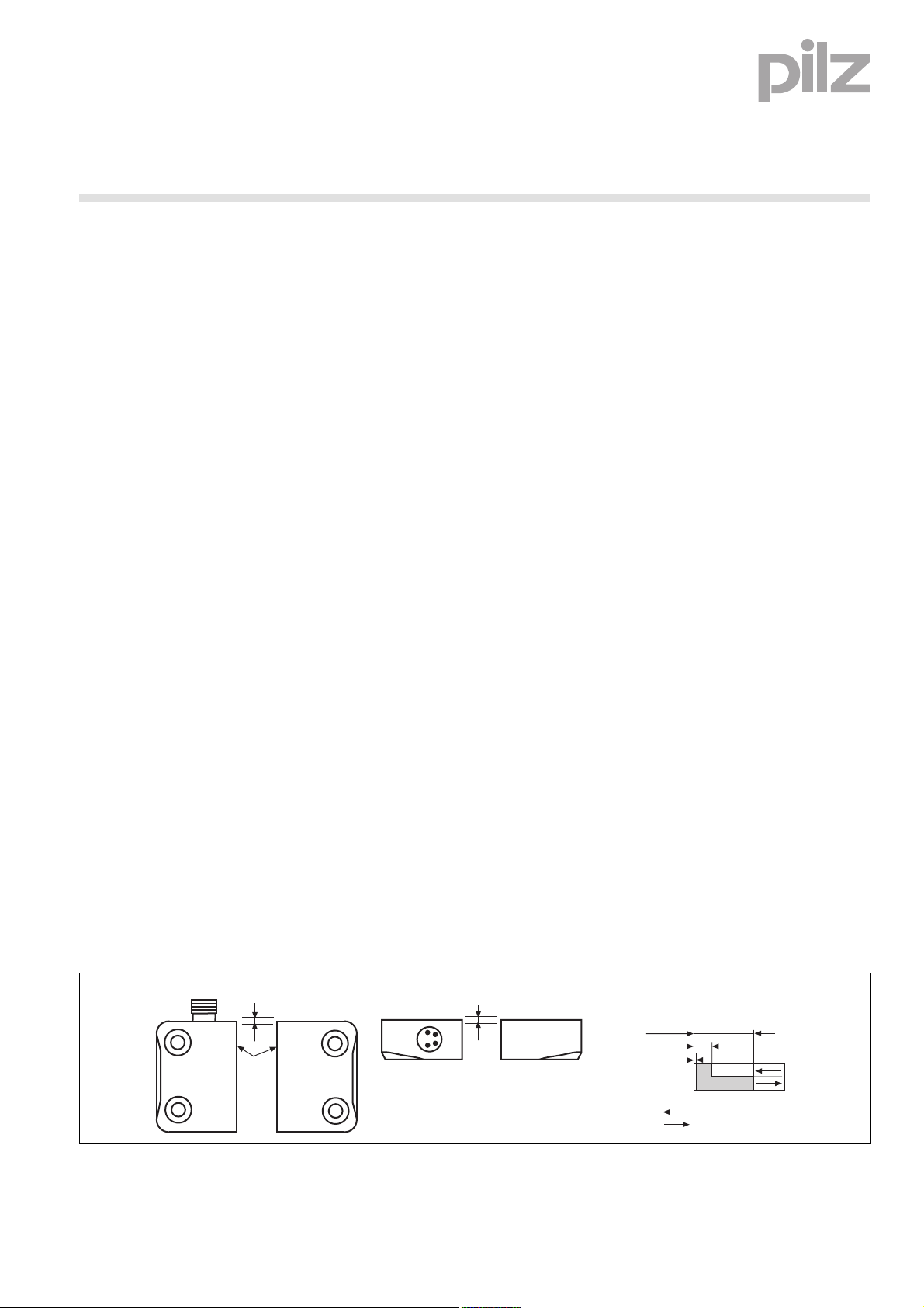
Seitenversatz/Lateral offset/
Décalage latéral
Höhenversatz/Height offset/
Décalage en hauteur
aktive Fläche
active area
surface active
Schaltabstand/Operating distance/
Portee de travail
s
ao
= 6
s
ar
= 25
Ein/On/Marche
Aus/Off/Arrêt
s
omin
= 0,5
PSEN ma2.1p/ATEX
22192-3FR-01PSEN ma2.1p/ATEX
Sicherheitsschalter PSEN ma2.1p-34
1392980363
Der Sicherheitsschalter erfüllt Forderungen der
EN 60204-1 und IEC 60204-1.
Der Sicherheitsschalter ist zugelassen für den
Einsatz in explosionsgefährdeten Bereichen
nach EN 60079-0: 2009, EN 60079-15: 2010,
EN 60079-31: 2009 Ex-Bereich Kategorie 3,
Zone 2 (Gas) II 3G Ex mc nAc IIC T6 und 22
(Stäube), II 3D Ex mc tc IIIC T80°C IP67.
Der Sicherheitsschalter erfüllt EN 60947-5-3
nur zusammen mit dem Betätiger PSEN 2.1-10
und hierfür zugelassenen Auswertegeräten.
Schließen Sie den Sicherheitsschalter nur an
Auswertegeräte an, die im Abschnitt "Anschlüsse" aufgeführt sind.
Zu Ihrer Sicherheit
547263243
Installieren und nehmen Sie das Gerät nur
dann in Betrieb, wenn Sie diese Betriebsanleitung gelesen und verstanden haben und
Sie mit den geltenden Vorschriften über Arbeitssicherheit und Unfallverhütung vertraut
sind.
Beachten Sie die VDE- sowie die örtlichen
Vorschriften, insbesondere hinsichtlich
Schutzmaßnahmen
Durch Öffnen des Gehäuses oder eigen-
mächtige Umbauten erlischt jegliche Gewährleistung.
777809547
Entfernen Sie die Schutzkappe erst unmittel-
bar vor Anschluss des Geräts.
Gerätemerkmale
1326675595
Zum Sicherheitsschalter gehört der Betätiger
PSEN 2.1-10
700964875
2 Reedkontakte (1 Öffner/1 Schließer)
510312331
gesicherter Schaltabstand: 6,0 mm
gesicherter Ausschaltabstand: 25,0 mm
510316939
eckige Bauform
510321547
Wirkweise magnetisch
510477451
Schaltspannung 24 V DC
1311891979
Reihenschaltung über Schnittstelle PSEN i1
763865611
LED zur Anzeige des Schaltzustands
Schaltabstände Operating distances Distances de commutation
Safety switch PSEN ma2.1p-34
The safety switch meets the requirements of
EN 60204-1 and IEC 60204-1.
The safety switch is approved for use in potentially explosive atmospheres in accordance
with EN 60079-0: 2009, EN 60079-15: 2010,
EN 60079-31: 2009 Ex area category 3, zone 2
(gas) II 3G Ex mc nAc IIC T6 and 22 (dust),
II 3D Ex mc tc IIIC T80°C IP67.
The safety switch only complies with
EN 60947-5-3 in conjunction with the actuator
PSEN 2.1-10 and its approved evaluation devices.
The safety switch should only be connected to
the evaluation devices listed under "Connections".
For your safety
Only install and commission the unit if you
have read and understood these operating
instructions and are familiar with the applicable regulations for health and safety at work
and accident prevention.
Ensure VDE and local regulations are met,
especially those relating to safety.
Any guarantee is rendered invalid if the hous-
ing is opened or unauthorised modifications
are carried out.
Do not remove the protective cap until you
are just about to connect the unit.
Unit features
The actuator PSEN 2.1-10 belongs to the
safety switch
2 reed contacts (1 N/C / 1 N/O)
Assured operating distance: 6,0 mm
Assured release distance: 25,0 mm
Square design
Works magnetically
Switching voltage 24 VDC
Series connection via PSEN i1 interface
LED to display switch status
Capteur de sécurité PSEN ma2.1p-34
Le capteur de sécurité satisfait aux exigences
de l'EN 60204-1 et de la CEI 60204-1.
Le capteur de sécurité est homologué pour une
utilisation dans des atmosphères explosives
selon l'EN 60079-0:2009, l'EN 60079-15:2010,
l'EN 60079-31:2009 zone Ex catégorie 3, zone
2 (gaz) II 3G Ex mc nAc IIC T6 et 22 (poussières), II 3D Ex mc tc IIIC T80°C IP67.
Le capteur de sécurité répond à la norme
EN 60947-5-3 uniquement s'il est combiné
avec l'actionneur PSEN 2.1-10 et les unités de
contrôle avec les homologations correspondantes.
Ne raccordez le capteur de sécurité qu'aux unités de contrôle répertoriées dans le paragraphe
« Raccordements ».
Pour votre sécurité
Vous n'installerez l'appareil et ne le mettrez
en service qu'après avoir lu et compris le
présent manuel d'utilisation et vous être familiarisé avec les prescriptions en vigueur
sur la sécurité du travail et la prévention des
accidents.
Respectez les normes locales ou VDE, particulièrement en ce qui concerne la sécurité.
L'ouverture de l'appareil ou sa modification
annule automatiquement la garantie.
Veuillez retirer le cache de protection avant
de raccorder l'appareil.
Caractéristiques de l'appareil
L'actionneur PSEN 2.1-10 est associé au
capteur de sécurité.
2 contacts Reed (1 contact à ouverture / 1
contact à fermeture)
Distance de commutation de sécurité :
6,0 mm
Distance de déclenchement de sécurité :
25,0 mm
architecture rectangulaire
actionnement magnétique
Tension commutée 24 V DC
Montage en série par l'intermédiaire de l'in-
terface PSEN i1
LED pour l'affichage de l'état de commuta-
tion
- 1 -
Page 2
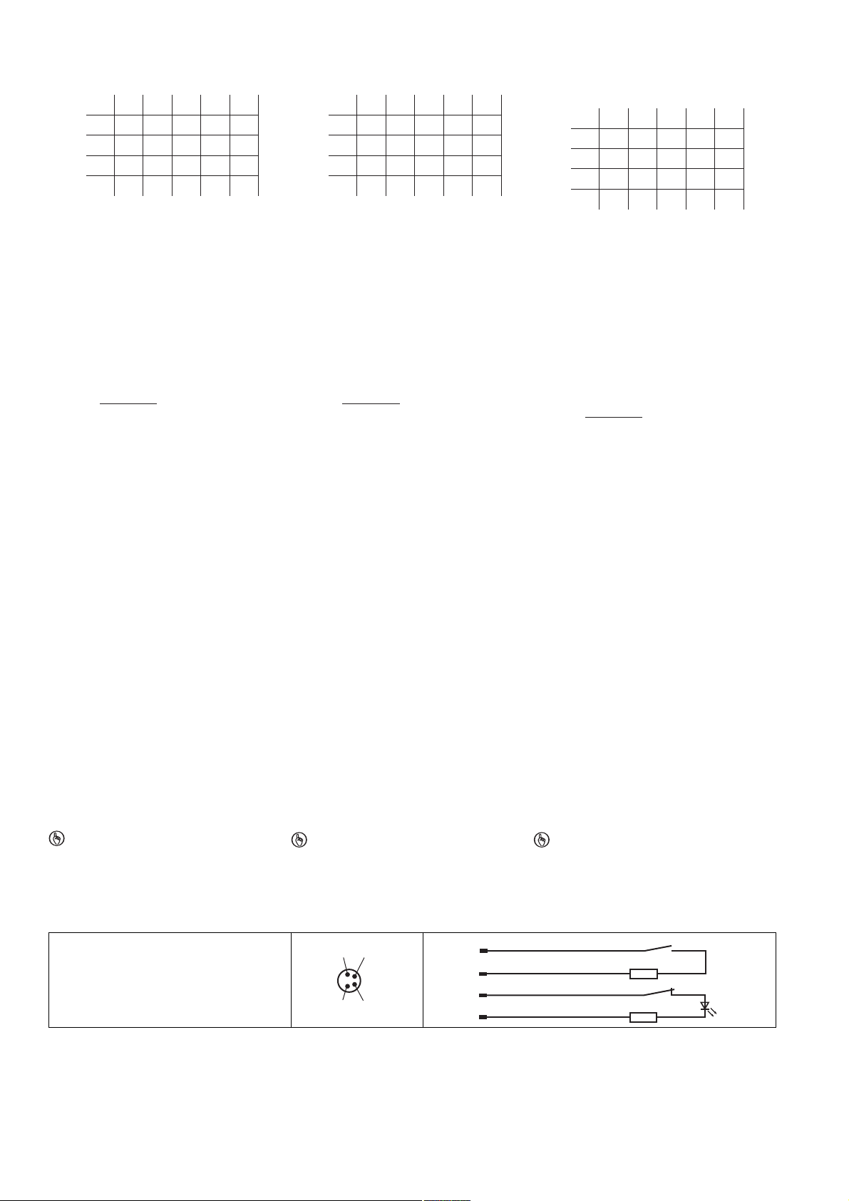
Seiten- und Höhenversatz Lateral and vertical offset Décalage latéral et en hauteur
5,0
2,0
1,0
3,0
4,0
3,02,01,0 4,0
3,04,54,55,5 4,0
2,54,54,55,0 3,5
0,53,54,54,5 2,5
-
-4,0
--
Seitenversatz/Lateral
offset/Décalage latéral
Höhenversatz/Height offset/
Décalage en hauteur
5,0
2,0
1,0
3,0
4,0
3,02,01,0 4,0
3,04,54,55,5 4,0
2,54,54,55,0 3,5
0,53,54,54,5 2,5
-
-4,0
--
Seitenversatz/Lateral
offset/Décalage latéral
Höhenversatz/Height offset/
Décalage en hauteur
5,0
2,0
1,0
3,0
4,0
3,02,01,0 4,0
3,04,54,55,5 4,0
2,54,54,55,0 3,5
0,53,54,54,5 2,5
-
-4,0
--
Seitenversatz/Lateral
offset/Décalage latéral
Höhenversatz/Height offset/
Décalage en hauteur
R
lmax
- R
i
Rl / km
I
max
=
R
lmax
- R
i
Rl / km
I
max
=
R
lmax
- R
i
Rl / km
I
max
=
1
2
3
4
blau/blue/bleu
weiß/white/blanc
braun/brown/marron
schwarz/black/noir
1
2
3 +
4
1424344587
Typischer Schaltabstand S
in mm
o
Typical operating distance S
in mm
o
Distance de commutation caractéristique S
en mm
o
Gesicherter Ausschaltabstand S
Max. 25 mm bei allen Höhen- und Seitenversätzen
:
ar
Assured release distance S
Max. 25 mm with all vertical and lateral off-
:
ar
sets
Distance de déclenchement de sécurité S
max. 25 mm pour tous les décalages laté-
raux et en hauteur
Die angegebenen Werte sind gültig bei einer
Temperatur von 20 °C.
The stated values are valid at a temperature of
20 °C.
Les valeurs indiquées sont valables pour une
température de 20 °C.
Verdrahtung
1424542475
Beachten Sie:
Angaben im Abschnitt „Technische Daten“
unbedingt einhalten.
Berechnung der max. Leitungslänge I
Eingangskreis des Auswertegerätes:
Wiring
Please note:
Information given in the "Technical details"
must be followed.
im
Calculation of the max. cable length l
max
the input circuit of the evaluation device:
Câblage
Important :
Respecter impérativement les données indi-
quées dans le paragraphe « Caractéristiques
in
max
techniques ».
Calcul de la longueur de câble max. I
le circuit d'entrée de l'unité de contrôle :
= max. Gesamtleitungswiderstand
R
lmax
(s. techn. Daten des Auswertegeräts)
Ri = Innenwiderstand Sensor (s. techn. Daten Sensor)
/ km = Leitungswiderstand/km des Ka-
R
l
bels (s. techn. Daten Kabelhersteller)
In Kombination mit einem Auswertegerät,
welches eine Plausibilitätsprüfung der beiden Sicherheitskontakte durchführt, ist eine
Klassifizierung nach EN 60947-5-3 des Sicherheitsschalters mit dem Auswertegerät in
PDF-M gegeben.
Überprüfen Sie in folgenden Fällen vor Inbe-
triebnahme die Funktion Querschlusserkennung:
– Bei Auswertegeräten mit Versorgungs-
spannung DC: Gesamtleitungswiderstand
≥ 15 Ohm pro Kanal
– Bei Auswertegeräten mit Versorgungs-
spannung AC: Gesamtleitungswiderstand
≥ 25 Ohm pro Kanal
– Wie Sie die Querschlussprüfung durchfüh-
ren müssen, entnehmen Sie der entsprechenden Bedienungsanleitung des
Auswertegeräts.
In combination with an evaluation device that
In the following cases, check the function
= Max. overall cable resistance (see
R
lmax
evaluation device's techn. details)
Ri = Internal sensor resistance (see sensor's
techn. details)
/ km = Cable resistance/km (see cable
R
l
manufacturer's techn. details)
performs a feasibility test on both safety contacts, the safety switch and evaluation device can be classified as PDF-M in
accordance with EN 60947-5-3.
that detects shorts across contacts prior to
commissioning:
– On evaluation devices with DC supply
voltage: Overall cable resistance ≥ 15
Ohms per channel
– On evaluation devices with AC supply volt-
age: Overall cable resistance ≥ 25 Ohms
per channel
– For details of how to perform the test for
shorts across the contacts, please refer to
the operating manual for the relevant evaluation device.
R
= résistance max. de l'ensemble du
lmax
câblage (voir les caractéristiques techni-
ques de l'unité de contrôle)
Ri = résistance interne du capteur (voir les
caractéristiques techniques du capteur)
R
/ km = résistance du câble/km (voir les
l
caractéristiques techniques du fabricant du
câble)
Une classification selon l'EN 60947-5-3 du
capteur de sécurité avec l'unité de contrôle
est établie au format PDF-M, en association
avec une unité de contrôle qui exécute un
contrôle de plausibilité des deux contacts de
sécurité.
Avant la mise en service, vérifiez dans les cas
suivants la fonction de détection des courtscircuits :
– Si les unités de contrôle disposent d'une
tension d'alimentation DC : résistance de
l'ensemble du câblage ≥ 15 ohm par canal
– Si les unités de contrôle disposent d'une
tension d'alimentation AC : résistance de
l'ensemble du câblage ≥ 25 ohm par canal
– Consultez le manuel d'utilisation de l'unité
de contrôle pour connaître la manière
d'exécuter le contrôle des courts-circuits.
Anschlüsse Connections Raccordements
Anschlussbelegung Terminal assignment Repérage des broches
777658251
WICHTIG
Die Farbkennzeichnung für die Anschlussleitung gilt nur für die als Zubehör erhältli-
chen Kabel von Pilz.
Der Sicherheitsschalter ist in unbetätigtem Zustand dargestellt.
Belegung des 4-pol. M8-Stiftsteckers/Assignment of the 4-pin M8 male connector/Repérage du connecteur mâle M8 à 4 pôles
NOTICE
The colour marking for the connection lead
only applies for the cable that Pilz supplies
as an accessory.
The safety switch is shown in an unoperated
condition.
IMPORTANT
Le marquage de couleur du câble de raccordement est uniquement valable pour les
câbles Pilz disponibles en tant qu'acces-
soires.
Le capteur de sécurité est représenté en position de repos.
max
ar
sur
:
- 2 -
Page 3
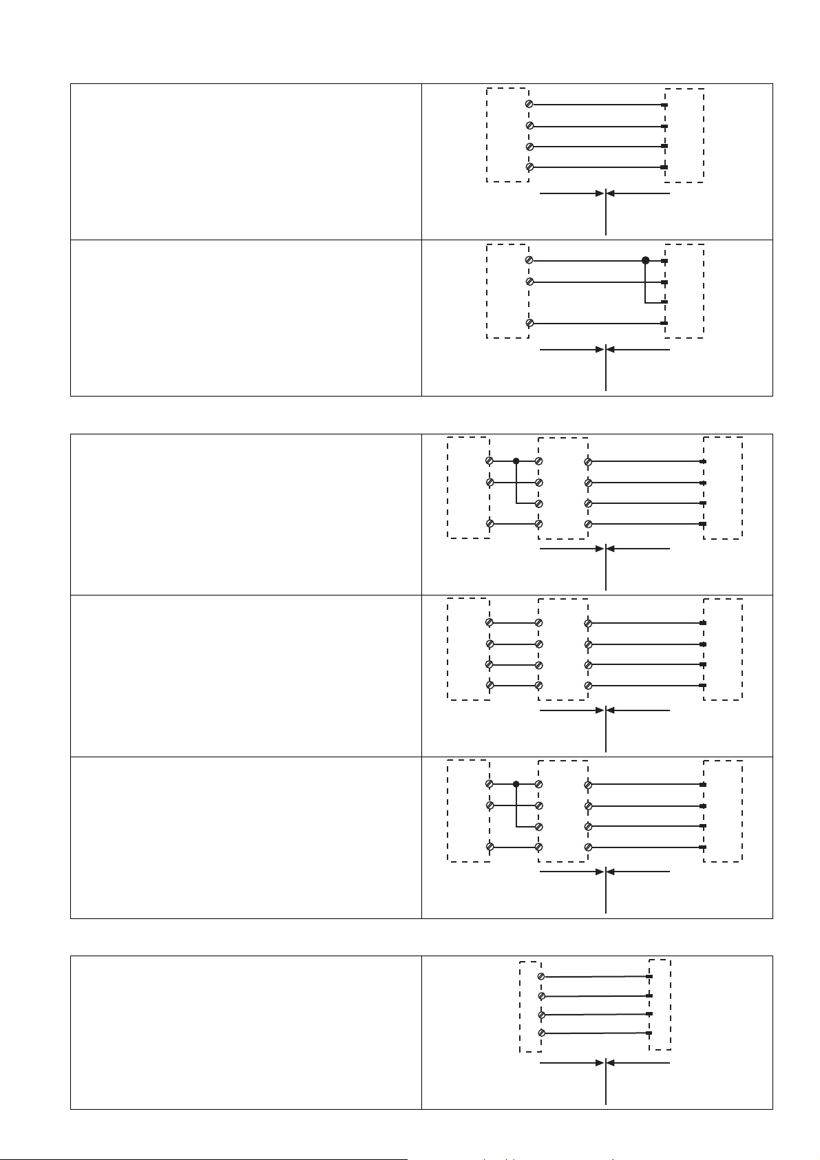
Anschluss an Auswertegeräte Connection to evaluation devices Raccordement aux unités de contrôle
PNOZ e3.1p
PNOZ e3vp 10 s
PNOZ e3vp 300 s
blau/blue/bleu
weiß/white/blanc
braun/brown/marron
schwarz/black/noir
S11
S12
S23
S24
1
2
3
4
Nicht-Ex-Bereich/Non-Ex
area/Zone Non Ex
Ex-Bereich/Ex area/
Zone Ex
PNOZ e5.13p
blau/blue/bleu
weiß/white/blanc
braun/brown/marron
schwarz/black/noir
A1
S32
S44
1
2
3
4
Nicht-Ex-Bereich/Non-Ex
area/Zone Non Ex
Ex-Bereich/Ex area/
Zone Ex
PNOZ e3.1p
PNOZ e3vp 10 s
PNOZ e3vp 300 s
ohne Querschlusserkennung/
without detection of shorts across contacts/
sans détection des courts-circuits
Nicht-Ex-Bereich/Non-Ex
area/Zone Non Ex
Ex-Bereich/Ex area/
Zone Ex
PNOZ e3.1p
PNOZ e3vp 10 s
PNOZ e3vp 300 s
mit Querschlusserkennung/
with detection of shorts across contacts/
avec détection des courts-circuits
Nicht-Ex-Bereich/Non-Ex
area/Zone Non Ex
Ex-Bereich/Ex area/
Zone Ex
PNOZ e5.13p
ohne Querschlusserkennung/
without detection of shorts across contacts/
sans détection des courts-circuits
Nicht-Ex-Bereich/Non-Ex
area/Zone Non Ex
Ex-Bereich/Ex area/
Zone Ex
Schutztür/safety gate/protecteur mobile
Schaltertyp 2/switch type 2/type du capteur 2
I0, I1: Eingänge/inputs/entrées
T0, T1: Taktausgänge/test pulse outputs/sorties
impulsionelles
T0
T1
I0
I1
1
2
3
4
blau/blue/
bleu
weiß/white/blanc
braun/brown/marron
schwarz/black/noir
Nicht-Ex-Bereich/Non-Ex
area/Zone Non Ex
Ex-Bereich/Ex area/
Zone Ex
Anschluss an PNOZ X, PNOZpower,
PNOZsigma, PNOZelog direkt
Direct connection to PNOZ X, PNOZpower,
PNOZsigma, PNOZelog
Raccordement aux PNOZ X, PNOZpower,
PNOZsigma, PNOZelog directement
Anschluss an PNOZ X, PNOZpower,
PNOZsigma, PNOZelog über PSEN i1
Connection to PNOZ X, PNOZpower,
PNOZsigma, PNOZelog via PSEN i1
S11
S12
S24
S11
S12
S23
S24
A1
S32
S44
Raccordement aux PNOZ X, PNOZpower,
PNOZsigma, PNOZelog via PSEN i1
PSEN i1
1
2
3
4
PSEN i1
1
2
3
4
PSEN i1
1
2
3
4
braun/brown/marron
11
weiß/white/blanc
12
blau/blue/bleu
13
schwarz/black/noir
14
braun/brown/marron
11
weiß/white/blanc
12
blau/blue/bleu
13
schwarz/black/noir
14
braun/brown/marron
11
weiß/white/blanc
12
blau/blue/bleu
13
schwarz/black/noir
14
1
2
3
4
1
2
3
4
1
2
3
4
Anschluss an PNOZmulti/PNOZmulti Mini
direkt
Direct connection to PNOZmulti/PNOZmulti
Mini
- 3 -
Raccordement au PNOZmulti / PNOZmulti
Mini directement
Page 4

Anschluss an PNOZmulti/PNOZmulti Mini
Schutztür/safety gate/protecteur mobile
Schaltertyp 2/switch type 2/type du capteur 2
I0, I1: Eingänge/inputs/entrées
T0, T1: Taktausgänge/test pulse outputs/sorties
impulsionelles
Nicht-Ex-Bereich/Non-Ex
area/Zone Non Ex
Ex-Bereich/Ex area/
Zone Ex
Schutztür/safety gate/protecteur mobile
Schaltertyp 3/switch type 3/type du capteur 3
I0, I1: Eingänge/inputs/entrées
O16, O17: Testtaktausgänge/test pulse outputs/sorties
impulsionelles
blau/blue/bleu
weiß/white/blanc
braun/brown/marron
schwarz/black/noir
O16
O17
I0
I1
1
2
3
4
Nicht-Ex-Bereich/Non-Ex
area/Zone Non Ex
Ex-Bereich/Ex area/
Zone Ex
Schutztür/safety gate/protecteur mobile
Schaltertyp 3/switch type 3/type du capteur 3
I0, I1: Eingänge/inputs/entrées
O16, O17: Testtaktausgänge/test pulse outputs/sorties
impulsionelles
Nicht-Ex-Bereich/Non-Ex
area/Zone Non Ex
Ex-Bereich/Ex area/
Zone Ex
über PSEN i1
Connection to PNOZmulti/PNOZmulti Mini
via PSEN i1
Raccordement au PNOZmulti / PNOZmulti
Mini via PSEN i1
Anschluss an PSS und PSSu mit oder ohne
SafetyBUS p direkt
Anschluss an PSS und PSSu mit oder ohne
SafetyBUS p über PSEN i1
T0
I0
T1
I1
Direct connection to PSS and PSSu with or
without SafetyBUS p
Connection to PSS and PSSu with or without
SafetyBUS p via PSEN i1
O16
I0
O17
I1
PSEN i1
1
2
3
4
braun/brown/marron
11
weiß/white/blanc
12
blau/blue/bleu
13
schwarz/black/noir
14
1
2
3
4
Raccordement aux PSS et PSSu avec ou
sans SafetyBUS p directement
Raccordement aux PSS et PSSu avec ou
sans SafetyBUS p via PSEN i1
PSEN i1
1
2
3
4
braun/brown/marron
11
weiß/white/blanc
12
blau/blue/bleu
13
schwarz/black/noir
14
1
2
3
4
ACHTUNG!
Die Sicherheitsschalter dürfen an einer PSS
nur mit dem Standardfunktionsbaustein
SB064 oder SB066 betrieben werden.
CAUTION!
The safety switches may only be operated
on a PSS in conjunction with standard
function block SB064 or SB066.
ATTENTION !
Les capteurs de sécurité ne doivent être
utilisés sur un PSS qu'avec le bloc de fonc-
tion standard SB064 ou SB066.
- 4 -
Page 5

Montage
516039435
Die Montagelage ist beliebig. Sicherheits-
schalter und Betätiger müssen jedoch parallel gegenüberliegend montiert werden.
Sicherheitsschalter und Betätiger möglichst
nicht auf ferromagnetisches Material montieren. Es sind Änderungen der Schaltabstände
zu erwarten. Benutzen Sie in diesem Fall die
Distanzplatte mit der Bestell-Nr. 534 310.
Befestigen Sie Sicherheitsschalter und Betä-
tiger ausschließlich mit Schrauben M4 mit
flacher Kopfunterseite (z. B. M4-Zylinderkopf- oder -Flachkopfschrauben). Anzugsdrehmoment max. 1 Nm. Verwenden Sie
Schrauben aus nicht magnetischem Material
(z. B. Messing).
Der Abstand zwischen zwei Systemen aus
Sicherheitsschalter und Betätiger muss mindestens 25 mm betragen.
Sicherheitsschalter und Betätiger
– von Eisenspänen fernhalten
– keinen starken Magnetfeldern aussetzen
– keinen starken Stößen oder Schwingun-
gen aussetzen
– nicht als Anschlag benutzen
1325555723
Die Schutzart IP67 wird nur bei Verwendung
der als Zubehör erhältlichen Anschlussleitungen von Pilz erreicht.
Justage
1326689547
Der Sicherheitsschalter darf nur mit dem zu-
gehörigen Betätiger PSEN 2.1-10 verwendet
werden.
Prüfen Sie die Funktion immer mit einem der
zugelassenen Auswertegeräte.
Bei unbetätigten Reedkontakten leuchtet die
LED (Schutzeinrichtung geöffnet oder Sicherheitsschalter und Betätiger falsch justiert). Die LED befindet sich im Öffnerkreis
des Sicherheitsschalters. Bei betätigten
Reedkontakten erlischt die LED.
Die angegebenen Schaltabstände (siehe
technische Daten) gelten nur, wenn Sicherheitsschalter und Betätiger parallel gegenüberliegend montiert sind. Andere
Anordnungen können zu abweichenden
Schaltabständen führen. Beachten Sie den
maximal zulässigen Seiten- und Höhenversatz (siehe "Schaltabstände" und "Max. Seiten- und Höhenversatz").
Installation
The unit can be installed in any position.
However, safety switches and actuators
must be positioned opposite each other in
parallel:
If possible, do not install the safety switch
and actuator on to ferromagnetic material.
Changes to the operating distances are to be
expected. In this case, use the spacer available under order number 534 310.
Safety switches and actuators should only
be secured using M4 screws with a flat head
(e.g. M4 cheese-head or pan head screws).
Torque setting max. 1 Nm. Use screws made
of non-magnetic material (e.g. brass).
The distance between two systems compris-
ing safety switch and actuator must be at
least 25 mm.
Safety switches and actuators
– Should be kept away from iron swarf
– Should not be exposed to strong magnetic
fields
– Should not be exposed to heavy shock or
vibration
– Should not be used as a limit stop
Protection type IP67 can only be achieved by
using the Pilz connection leads available as
an accessory.
Adjustment
The safety switch may only be used with the
corresponding actuator PSEN 2.1-10.
Always test the function with one of the ap-
proved evaluation devices.
The LED lights when the reed contacts are
unoperated (safety device open or safety
switch and actuator wrongly adjusted). The
LED is in the safety switch's N/C circuit. The
LED goes out when the reed contacts are operated.
The stated operating distances (see Techni-
cal details) only apply when the safety switch
and actuator are installed facing each other
in parallel. Operating distances may deviate
if other arrangements are used. Note the
maximum permitted lateral and vertical offset (see "Operating distances" and "Max. lateral and vertical offset").
Installation
Le sens de montage n'a pas d'importance.
Cependant, le capteur de sécurité et l'actionneur doivent être montés l'un en face de
l'autre de manière parallèle.
Évitez d'installer le capteur de sécurité et
l'actionneur sur du matériel ferromagnétique.
Cela pourrait affecter les distances de commutation. Dans ce cas, utilisez la plaque
d'écartement portant la référence 534 310.
Pour fixer le capteur de sécurité et l'action-
neur, utilisez uniquement des vis M4 dont la
tête présente une face inférieure plate
(exemple : vis M4 cylindriques ou à tête plate). Couple de serrage max. 1 Nm. Utilisez
des vis dans des matériaux non magnétiques
(exemple : en laiton).
La distance entre deux systèmes composés
d'un capteur de sécurité et d'un actionneur
doit être d'au moins 25 mm.
Le capteur de sécurité et l'actionneur
– doivent être éloignés des copeaux métalli-
ques
– ne doivent pas être exposés à des champs
magnétiques élevés
– ne doivent pas subir des chocs ou vibra-
tions importants
– ne doivent pas être utilisés comme butée
L'indice de protection IP67 est seulement at-
teint si on utilise des câbles de raccordement
de Pilz fournis en tant qu'accessoires.
Ajustement
Le capteur de sécurité ne doit être utilisé
qu'avec l'actionneur PSEN 2.1-10 correspondant.
Vérifiez toujours le fonctionnement avec
l'une des unités de contrôle homologuées.
La LED s'allume lorsque les contacts Reed
ne sont pas actionnés (dispositif de protection ouvert ou capteur de sécurité et actionneur mal ajustés). La LED se trouve dans le
circuit du contact à ouverture du capteur de
sécurité. Lorsque les contacts Reed sont activés, la LED s'éteint.
Les distances de commutation indiquées
dans les caractéristiques techniques sont
valables uniquement lorsque le capteur de
sécurité et l'actionneur sont montés l'un en
face de l'autre de manière parallèle. D'autres
montages peuvent conduire à des distances
de commutation divergentes. Respectez le
décalage latéral et en hauteur maximal autorisé (voir « Distances de commutation » et
« Décalage latéral et en hauteur maximum »).
- 5 -
Page 6

ATEX Einbau- und Betriebsvorschriften
26
19
22
36
10,6
M8x1
8,5
4,5
9
13
6,5
LED
26
19
22
36
8,5
4,5
13
Safety switch
Actuator
(X)
1474262795
WARNUNG!
Gefahr der Beschädigung durch mechanische Belastung. Strom führende Bauteile
des Sicherheitsschalters im explosionsgefährdeten Bereich können freigelegt werden.
Lebensgefahr!
Schützen Sie die Kanten des Bodens
des Sicherheitsschalters vor Schlägen.
Dies kann z. B. durch eine vollflächige
Montage erfolgen (siehe Montagebeispiel).
Beachten Sie außerdem die weiteren An-
gaben im Abschnitt Montage.
ATEX installation and operating regulations (X)
WARNING!
Risk of damage due to mechanical load.
Live components on the safety switch in
the potentially explosive area may become
exposed.
Threat to life!
Protect the edges of the safety switch
base from shock. This can be achieved
by full face installation, for example (see
Installation example).
Please also refer to the additional infor-
mation in the Installation section.
Prescriptions d'installation et d'exploitation ATEX (X)
AVERTISSEMENT !
Risque d'endommagement dû à une char-
ge mécanique. Des éléments conducteurs
du capteur de sécurité situé en atmosphère
explosive peuvent se révéler.
Danger de mort !
Protégez les côtés de la face inférieure
du capteur de sécurité contre les chocs.
Cette protection peut être assurée par un
montage sur une surface plane (voir
exemple de montage).
Tenez également compte des autres in-
dications du paragraphe Montage.
1474265483
Montagebeispiel:
Der Sicherheitsschalter ist vollständig auf dem
Untergrund montiert.
Die Kanten des Bodens des Sicherheitsschalters sind somit gegen Schläge geschützt.
Abmessungen in mm Dimensions in mm Dimensions en mm
Installation example:
The full face of the safety switch is installed on
the subplate.
As a result, the edges of the safety switch base
are protected from shock.
Exemple de montage :
Le capteur de sécurité est entièrement monté
sur la face inférieure.
Les côtés de la face inférieure du capteur de
sécurité sont ainsi protégés contre les chocs.
- 6 -
Page 7

Technische Daten Technical details Caractéristiques techniques
Elektrische Daten Electrical data Données électriques
Schaltspannung Switching voltage Tension de commutation 24 V
Innenwiderstand Internal resistance Résistance interne 100 Ohm
Max. Schaltstrom Sicherheitskon-
takte
Max. switching current for safety
contacts
Courant max. de commutation des
contacts de sécurité
10,00 mA
Max. Strom Max. current Courant max. 10 mA
Max. Schaltfrequenz Max. switch frequency Fréquence de commutation max. 10 Hz
Umweltdaten Environmental data Données sur l'environnement
ATEX-Zulassung ATEX app rova l Ho m o l ogation ATEX SEV 12 ATEX 0121 X
ATEX Kategorie Gas ATEX Category Gas ATEX catégorie gaz II 3G Ex mc nAc IIC T6
ATEX Kategorie Staub ATEX Category Dust ATEX catégorie poussière II 3D Ex mc tc IIIC T80°C IP67
Einsatzbereich Application area Champ d'application X: -25°C ≤ ta ≤ +55°C
Umgebungstemperatur Ambient temperature Température d'utilisation -25 - 55 °C
Schwingungen nach EN 60947-5-2 Vibration to EN 60947-5-2 Vibrations selon EN 60947-5-2
Frequenz Frequency Fréquence 10,0 - 55,0 Hz
Amplitude Amplitude Amplitude 1,00 mm
EMV EMC CEM EN 60947-5-3
Schock nach EN 60947-5-2 Shock to EN 60947-5-2 Chocs selon EN 60947-5-2
Schockbeschleunigung Shock acceleration Accélération de choc 30g
Schockzeit Shock time Temps de choc 11 ms
Verschmutzungsgrad Pollution degree Niveau d'encrassement 3
Bemessungsisolationsspannung Rated insulation voltage Tension assignée d'isolement 25 V
Bemessungsstoßspannungsfestig-
keit
Rated impulse withstand voltage Tension assignée de tenue aux
chocs
0,33 kV
Mechanische Daten Mechanical data Données mécaniques
Betätiger Actuator Actionneur PSEN 2.1-10
Hysterese typ. Hysteresis typ. Hystérésis env. 2,0 mm
Schaltabstände Switching distances Distances de commutation
Gesicherter Schaltabstand S
Min. Schaltabstand S
omin
Gesicherter Ausschaltabstand S
Min. Abstand zwischen Sicherheitsschaltern
Assured operating distance S
ao
Min. operating distance S
Assured release distance S
ar
Min. distance between safety
switches
omin
ar
Distance de commutation de sécu-
ao
rité S
ao
Distance de commutation min.
S
omin
Distance de déclenchement de sécurité S
ar
Distance minimale entre les capteurs de sécurité
6,0 mm
0,5 mm
25,0 mm
25 mm
Anschlussart Connection type Type de connection M8, 4-pol. Stiftstecker/
M8, male 4-pin connector/
M8, connecteur mâle à 4 broches
Leitung Cable Câble LiYY 4 x 0,25 mm
2
Schutzart Gehäuse Protection type, housing Indice de protection du boîtier IP67
Gehäusematerial Housing material Matériau du boîtier PC
Abmessungen siehe Abbildung Dimensions, see graphic Dimensions, voir l'illustration
Gewicht Weight Poids
Sicherheitsschalter Safety switch Capteur de sécurité 20 g
Betätiger Actuator Actionneur 20 g
Sicherheitstechnische Kenndaten
B10d nach EN ISO 13849-1 und
EN IEC 62061, I = 10 mA
Safety-related characteristic
data
B10d in accordance with
EN ISO 13849-1 and EN IEC 62061,
Caractéristiques techniques de
sécurité
B10d selon l'EN ISO 13849-1 et
l'EN CEI 62061, I = 10 mA
2.000.000
I = 10 mA
Es gelten die 2012-09 aktuellen Ausgaben der
Normen.
The standards current on 2012-09 apply. Les versions actuelles 2012-09 des normes
s'appliquent.
- 7 -
Page 8

Bestelldaten/Order reference/ Références
Typ/Type/ Type Merkmale/Features/ Caractéristiques Bestell-Nr./Order no./
Référence
PSEN ma2.1p-34/PSEN 2.1-10 Magnetischer Sicherheitsschalter mit Stecker M8, 4-polig, ATEX, mit LED, Be-
506 413
tätiger mit gesichertem Schaltabstand 6 mm/
Magnetic safety switch with M8 connector, 4-pin, ATEX, with LED, actuator
with assured operating distance 6 mm/
Capteur de sécurité magnétique avec connecteur M8, à 4 broches, ATEX, avec
LED, actionneur avec distance de commutation de sécurité de 6 mm
Bestelldaten Einzelkomponenten/Order reference: Component parts/ Référence des composants individuels
Typ/Type/ Type Merkmale/Features/ Caractéristiques Bestell-Nr./Order no./
Référence
PSEN ma2.1p-34 (switch) Magnetischer Sicherheitsschalter mit Stecker M8, 4-polig, ATEX, mit LED/
506 404
Magnetic safety switch with M8 connector, 4-pin, ATEX, with LED/
Capteur de sécurité magnétique avec connecteur M8, à 4 broches, ATEX, avec
LED
PSEN 2.1-10 Magnetischer Betätiger/Magnetic actuator/ Actionneur magnétique 512 110
EG-Konformitätserklärung
1464523403
Diese(s) Produkt(e) erfüllen die Anforderungen
der Richtlinie 2006/42/EG über Maschinen und
der Richtlinie 94/9/EG (ATEX) des europäischen Parlaments und des Rates. Die vollständige EG-Konformitätserklärung finden Sie im
Internet unter www.pilz.com.
Bevollmächtigter: Norbert Fröhlich, Pilz GmbH
& Co. KG, Felix-Wankel-Str. 2, 73760 Ostfildern, Deutschland
22192-3FR-012012-11Printed in Germany
EC Declaration of Conformity
This product/these products meet the requirements of the directive 2006/42/EC for machinery and directive 94/9/EC (ATEX) of the
European Parliament and of the Council. The
complete EC Declaration of Conformity is available on the Internet at www.pilz.com..
Representative: Norbert Fröhlich, Pilz GmbH &
Co. KG, Felix-Wankel-Str. 2, 73760 Ostfildern,
Germany
Déclaration de conformité CE
Ce(s) produit(s) satisfait (satisfont) aux exigences de la directive 2006/42/CE concernant les
machines et à la directive 94/9/CE (ATEX) du
Parlement européen et du Conseil. Vous trouverez la déclaration de conformité CE complète
sur notre site internet www.pilz.com.
Mandataire : Norbert Fröhlich, Pilz GmbH & Co.
KG, Felix-Wankel-Str. 2, 73760 Ostfildern, Allemagne
Originalbetriebsanleitung/Original instructions/Notice originale
22192-3FR-01, 2012-11 Printed in Germany
 Loading...