

Page 1
Units
PSENmag
PSEN ma1.3b-25
PSEN ma1.3b-252.2SEN-D-2-014-2007-03UnitsPSENmagPSEN ma1.3b-25PSEN ma1.3b-25
Magnetic safety switches for monitoring the position of movable guards in
accordance with EN 60947-5-3
Approvals
PSEN ma1.3b-25
Pending
Pending
Unit features
` The actuator PSEN ma1,3-08 be-
longs to the safety switch
` Safety switch with cable (5 m/ 10 m)
` 2 reed contacts (N/O)
` 1 auxiliary contact (N/O)
` Assured operating distance: 8 mm
` Assured release distance: 15 mm
` Safety switch and actuator with
M12 round design
` Works magnetically
` Switching voltage 24 VDC
` LED to display switch status
Unit description
The safety switch meets the requirements of EN 60204-1 and IEC 60204-
1.
The safety switch is approved for use
in potentially explosive atmospheres in
accordance with EN 50021, Ex area
Category 3, Zone 2 (gas) and 22 (dust),
(II 3GD EEx nC IIC T6).
The safety switch only complies with
EN 60947-5-3 in conjunction with the
PSEN ix1 interface, the actuator PSEN
ma1,3-08 and its approved evaluation
devices. The safety switch should only
be connected to the evaluation devices listed under "Connections".
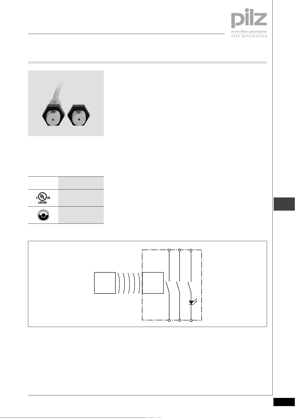
2.2
Block diagram
Actuator
Magnet
Function description
If the actuator is within the response
range, the magnets switch the reed
contacts on the safety switch. If the
actuator is outside the response range
(safety gate open), the reed contacts
on the safety switch will switch.
Safety switch
Pilz GmbH & Co. KG, Sichere Automation, Felix-Wankel-Straße 2, 73760 Ostfildern, Germany
Telephone: +49 711 3409-0, Telefax: +49 711 3409-133, E-Mail: pilz.gmbh@pilz.de
SEN-D-2-014-2007-03
2.2-191
Page 2
Units
PSENmag
PSEN ma1.3b-25
Operating distances
2.2
Seitenversatz/Lateral offset/
Décalage latéral
Lateral and vertical offset
with M12 actuator
` Assured operating distance S
ao
mm:
Höhenversatz/Height offset/
Vertical offset
Décalage en hauteur
420
420
0
0
2
2
4
4
Lateral offset
Seitenversatz/Lateral
offset/Décalage latéral
` Assured release distance S
5,57,08,0
5,57,08,0
4,06,07,0
4,06,07,0
3,05,06,0
3,05,06,0
:
ar
Max. 15 mm with all vertical and lat-
eral offsets
The stated values are valid at a temperature of 20 °C.
Wiring
in
Please note:
` Information given in the “Technical
details” must be followed.
` Calculation of the max. cable runs
in the input circuit:
l
max
R
lmax
=
I
max
Rl / km
R
= max. overall cable resist-
lmax
ance (see Technical details)
/ km = cable resistance/km
R
l
` When using evaluation devices with
delay-on de-energisation contacts,
please note:
–Delay time ≤ 30 s: Delay-on de-
energisation contacts satisfy the
requirements of category 3 in accordance with EN 954-1 and the
requirements of a PDF with single-fault tolerance (PDF-S).
–Delay time ≥ 30 s: Delay-on de-
energisation contacts satisfy the
requirements of Category 1 in
accordance with EN 954-1 and
the requirements of a PDF with
designed reliability (PDF-D).
` In the following commissioning cas-
es, check the function that detects
shorts across contacts:
– On evaluation devices with DC
supply voltage: Overall cable resistance ≥ 15 Ohms per channel
– On evaluation devices with AC
supply voltage: Overall cable resistance ≥ 25 Ohms per channel
– For details of how to perform the
test for shorts across the contacts, please refer to the operating manual for the relevant
evaluation device.
Höhenversatz/Height offset/
Décalage en hauteur
Schaltabstand/
Operating distance/
= 15
ar
= 8
ao
Portee de travail
Ein/On/Marche
Aus/Off/Arrêt
s
s
2.2-192
SEN-D-2-014-2007-03Pilz GmbH & Co. KG, Sichere Automation, Felix-Wankel-Straße 2, 73760 Ostfildern, Germany
Telephone: +49 711 3409-0, Telefax: +49 711 3409-133, E-Mail: pilz.gmbh@pilz.de
Page 3
Units
PSENmag
PSEN ma1.3b-25
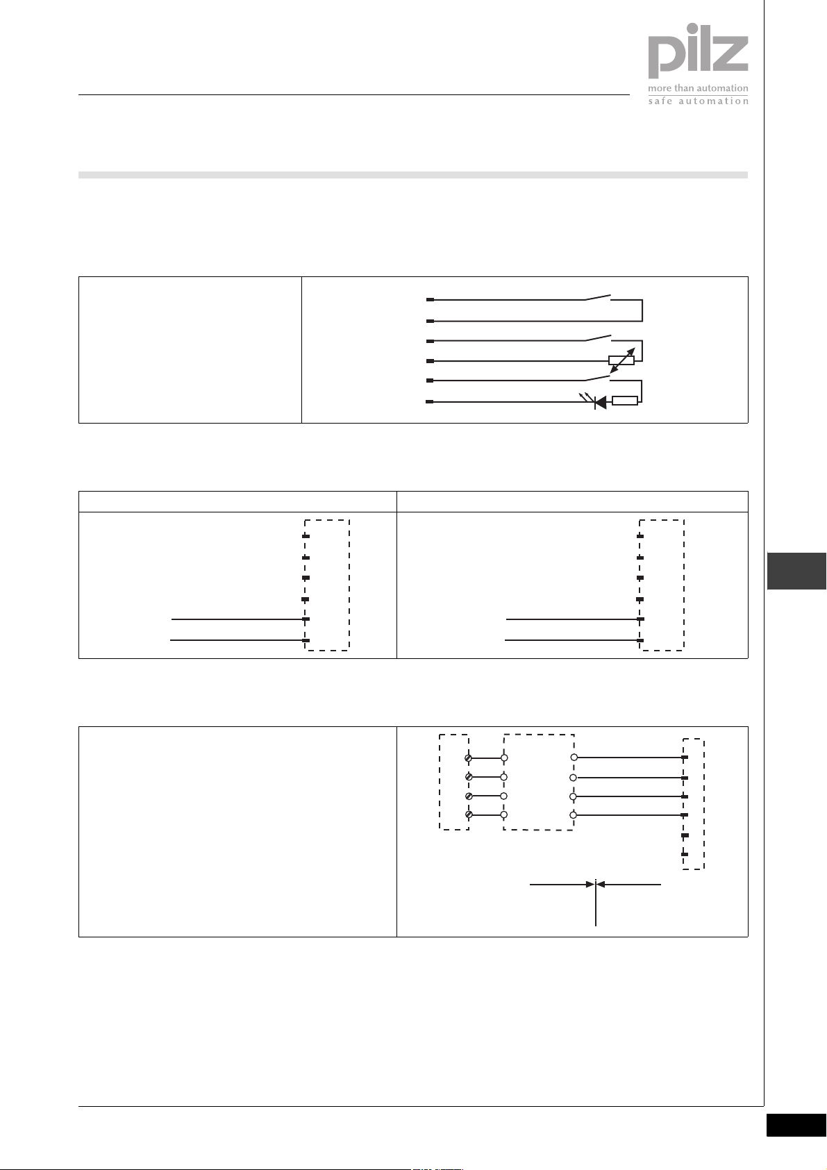
Connections The safety switch is shown in an unop-
erated condition.
Belegung des 6-adrigen Kabels/Layout of
the 6-core cable/Repérage du câble à 6
conducteurs
braun/brown/marron
1
weiß/white/blanc
2
blau/blue/bleu
3
schwarz/black/noir
4
rot/red/rouge
5+
grün/green/vert
6
` Auxiliary contact with LED connec-
tion
PNOZ X, PNOZelog, PNOZpower, PNOZsigma connection PNOZmulti, PSS connection
1
2
3
4
5
6
A1/+24 V
I7
A1/+24 V
GND
rot/red/rouge
grün/green/vert
` Connection to PNOZ X, PNOZelog,
PNOZpower, PNOZsigma
rot/red/rouge
grün/green/vert
1
2
3
4
5
6
2.2
PSEN ix1
PNOZ p1p
PNOZ p1p
PNOZ p1vp
PNOZ p1vp
PNOZ X2/X2P
PNOZ X2/X2P
PNOZ X2.1
PNOZ X2.1
(nur 24 V DC/
(nur 24 V DC/
24 V DC only/
24 V DC only/
24 V DC seulement)
24 V DC seulement)
PNOZ X2.3P
PNOZ X2.3P
PNOZ X2.7P
PNOZ X2.7P
PNOZ X2.8P/X2.9P
PNOZ X2.8P/X2.9P
Pilz GmbH & Co. KG, Sichere Automation, Felix-Wankel-Straße 2, 73760 Ostfildern, Germany
Telephone: +49 711 3409-0, Telefax: +49 711 3409-133, E-Mail: pilz.gmbh@pilz.de
PNOZ X2C
PNOZ X2C
PNOZ X2.1C
PNOZ X2.1C
(nur 24 V DC/
(nur 24 V DC/
24 V DC only/
24 V DC only/
24 V DC seulement)
24 V DC seulement)
PNOZ X4/X8P
PNOZ X4/X8P
PNOZ X9/X9P
PNOZ X9/X9P
PNOZ X10/X10.1
PNOZ X10/X10.1
PNOZ X10.11P
PNOZ X10.11P
PNOZ Ex
PNOZ Ex
PNOZ e1p
PNOZ e1p
PNOZ e1.1p
PNOZ e1.1p
PNOZ e1vp
PNOZ e1vp
PNOZ e6.1p
PNOZ e6.1p
PNOZ e6vp
PNOZ e6vp
PNOZ s3
PNOZ s3
PNOZ s4
PNOZ s4
PNOZ s5
PNOZ s5
S21
S22
S11
S12
Nicht-Ex-Bereich/Non-Ex
area/Zone Non Ex
1
2
3
4
braun/brown/marron
11
weiß/white/blanc
12
blau/blue/bleu
13
schwarz/black/noir
14
Ex-Bereich/Ex area/
Zone Ex
1
2
3
4
5
6
SEN-D-2-014-2007-03
2.2-193
Page 4

Units
PSENmag
PSEN ma1.3b-25
2.2
PNOZ X5
PNOZ X5J
PNOZ 11
PNOZ 16
PNOZ X11P
PNOZ X13
PNOZ X3.1
PNOZ X3P
PNOZ X2.5P
PNOZ X3
PNOZ X3.10P
PNOZ XV2
PNOZ XV2P
PNOZ XV3
PNOZ XV3P
PSEN ix1
S11
S22
S11
S12
Nicht-Ex-Bereich/Non-Ex
area/Zone Non Ex
S21
S22
S31
S32
Nicht-Ex-Bereich/Non-Ex
area/Zone Non Ex
1
2
3
4
PSEN ix1
1
2
3
4
braun/brown/marron
11
weiß/white/blanc
12
blau/blue/bleu
13
schwarz/black/noir
14
Ex-Bereich/Ex area/
Zone Ex
braun/brown/marron
11
weiß/white/blanc
12
blau/blue/bleu
13
schwarz/black/noir
14
Ex-Bereich/Ex area/
Zone Ex
1
2
3
4
5
6
1
2
3
4
5
6
PNOZ X6 (mit Brücke/with link/avec pontage Y3-Y4)PNOZ X6 (mit Brücke/with link/avec pontage Y3-Y4)
PMUT X1P
PSEN ix1
S23
S24
S11
S12
Nicht-Ex-Bereich/Non-Ex
area/Zone Non Ex
S61
S62
S51
S52
Nicht-Ex-Bereich/Non-Ex
area/Zone Non Ex
1
2
3
4
PSEN ix1
1
2
3
4
braun/brown/marron
11
weiß/white/blanc
12
blau/blue/bleu
13
schwarz/black/noir
14
Ex-Bereich/Ex area/
Zone Ex
braun/brown/marron
11
weiß/white/blanc
12
blau/blue/bleu
13
schwarz/black/noir
14
Ex-Bereich/Ex area/
Zone Ex
1
2
3
4
5
6
1
2
3
4
5
6
2.2-194
SEN-D-2-014-2007-03Pilz GmbH & Co. KG, Sichere Automation, Felix-Wankel-Straße 2, 73760 Ostfildern, Germany
Telephone: +49 711 3409-0, Telefax: +49 711 3409-133, E-Mail: pilz.gmbh@pilz.de
Page 5

Units
PSENmag
PSEN ma1.3b-25
PNOZ e5.11p
` Connection to PNOZmulti
Schutztür/safety gate/protecteur mobile
Schaltertyp 3/switchtype 3/type du capteure 3
I0, I1: Eingänge/inputs/entrées
T0, T1: Taktausgänge/test pulse outputs/sorties
impulsionelles
PSEN ix1
A1
S32
A1
S42
Nicht-Ex-Bereich/Non-Ex
area/Zone Non Ex
T0
I0
T1
I1
1
2
3
4
1
2
3
4
11
12
13
14
PSEN ix1
11
12
13
14
braun/brown/marron
weiß/white/blanc
blau/blue/bleu
schwarz/black/noir
Ex-Bereich/Ex area/
Zone Ex
braun/brown/marron
weiß/white/blanc
blau/blue/bleu
schwarz/black/noir
1
2
3
4
5
6
1
2
3
4
5
6
2.2
` Connection to PSS with and with-
out SafetyBUS p
Schutztür/safety gate/protecteur mobile
Schaltertyp 3/switchtype 3/type du capteure 3
I0, I1: Eingänge/inputs/entrées
O16, O17: Taktausgänge/test pulse outputs/sorties
impulsionelles
CAUTION!
The safety switches may only be operated on a PSS in conjunction with
standard function block SB064 or
SB066.
Nicht-Ex-Bereich/Non-Ex
area/Zone Non Ex
PSEN ix1
T0
I0
T1
I1
Nicht-Ex-Bereich/Non-Ex
area/Zone Non Ex
1
2
3
4
Ex-Bereich/Ex area/
Zone Ex
braun/brown/marron
11
weiß/white/blanc
12
blau/blue/bleu
13
schwarz/black/noir
14
Ex-Bereich/Ex area/
Zone Ex
1
2
3
4
5
6
Pilz GmbH & Co. KG, Sichere Automation, Felix-Wankel-Straße 2, 73760 Ostfildern, Germany
Telephone: +49 711 3409-0, Telefax: +49 711 3409-133, E-Mail: pilz.gmbh@pilz.de
SEN-D-2-014-2007-03
2.2-195
Page 6

Units
PSENmag
PSEN ma1.3b-25
2.2
Installation
` When installing make sure you
comply with the requirements of
DIN EN 1088
` If possible, do not install the safety
switch and actuator on to ferromagnetic material. Changes to the operating distances are to be expected.
` The distance between two systems
comprising safety switch and actuator must be at least 25 mm.
` Safety switch and actuator
– Keep away from iron swarf
– Do not expose to strong mag-
netic fields
– Do not expose to heavy shock or
vibration
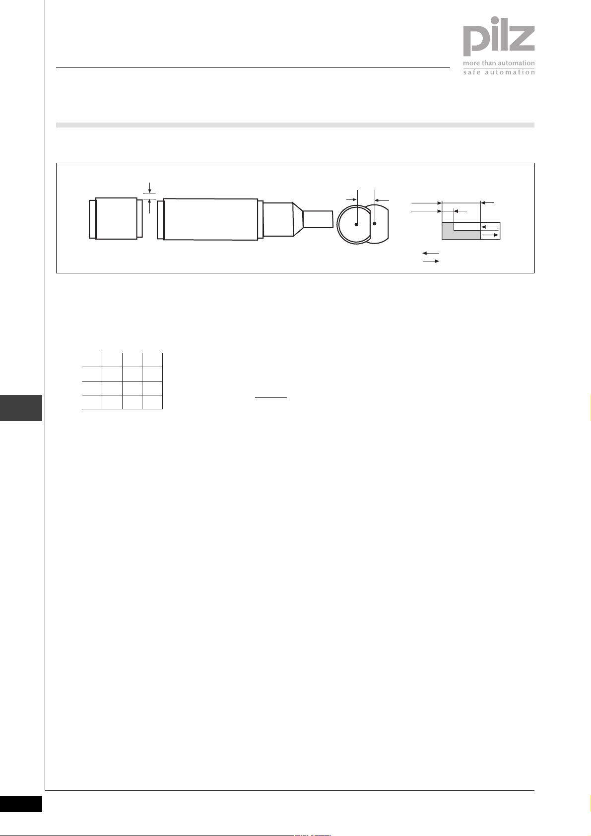
Dimensions in mm
Safety switch
– Do not use as a limit stop
– For fixed wiring only
` The unit can be installed in any po-
sition. The safety switch and actuator must be installed so that the
bevelled surfaces face each other
precisely.
` The safety switch and actuator
should only be secured using M12
nuts made of non-magnetic material (e.g. Messing). Torque setting
max. 300 Ncm.
Adjustment
` The safety switch may only be used
with the corresponding actuator
PSEN ma1,3-08.
` Always test the function with the
PSEN ix1 interface and one of the
approved evaluation devices.
` The stated operating distances (see
Technical details) only apply when
the safety switch and actuator are
installed facing each other in parallel. Switching distances may deviate if other arrangements are used.
Note the maximum permitted lateral and vertical offset (see "Operating distances" and "Max. lateral
and vertical offset").
Actuator
2
42,6
59,2
M12 x 1
11
2 12,5
NOTICE
This data sheet is only intended for use
during configuration. For installation
erating instructions supplied with the
unit.
and operation, please refer to the op-
Technical details
ATEX category II 3GD Eex nC IIC T6
Switching distances
Assured operating distance S
Min. operating distance S
Assured release distance S
Switching voltage 24 V
Max. switching current for reed contacts 0.20 A
Max. switching current for auxiliary contacts 10 mA
Max. breaking capacity for reed contacts 5.0 W
Max. switch frequency 1 Hz
Actuator PSEN ma1,3-08
Ambient temperature -25 - 70 °C
ao
omin
ar
8 mm
0.5 mm
15 mm
M12 x 1
11
212
25
2
2.2-196
SEN-D-2-014-2007-03Pilz GmbH & Co. KG, Sichere Automation, Felix-Wankel-Straße 2, 73760 Ostfildern, Germany
Telephone: +49 711 3409-0, Telefax: +49 711 3409-133, E-Mail: pilz.gmbh@pilz.de
Page 7

Units
PSENmag
PSEN ma1.3b-25
Technical details
Vibration to EN 60947-5-2
Frequency 10 - 55 Hz
Amplitude 0.35 mm
Shock stress 30 g , 11 ms
Connection type 10m cable
Cable LiYY 6 x 0,25 mm
Protection type IP69K
Housing material PBT
Dimensions
Diameter M12
Safety switch
Depth 59.2 mm
Actuator
Depth 25 mm
Weight
Safety switch 430 g
Actuator 10 g
2
The standards current on 2007-03 apply.
Order reference
Type Quan-
tity
PSEN ma1.3a-25 1/1 magnetic Safety switch/actuator M12 506 225
Operation Features Order no.
2.2
Pilz GmbH & Co. KG, Sichere Automation, Felix-Wankel-Straße 2, 73760 Ostfildern, Germany
Telephone: +49 711 3409-0, Telefax: +49 711 3409-133, E-Mail: pilz.gmbh@pilz.de
SEN-D-2-014-2007-03
2.2-197
 Loading...