

Page 1
20950-06
PSEN ix1
4
D Betriebsanleitung
4
GB Operating instructions
4
F Manuel d'utilisation
Die Schnittstelle PSEN ix1
Mit Hilfe der Schnittstelle PSEN ix1 lassen
sich mehrere Sicherheitsschalter oder
Positionsschalter an Sicherheitsschaltgeräte
der Serie PNOZ anschließen und auswerten.
An das PSEN ix1 dürfen angeschlossen
werden:
• Sicherheitsschalter PSEN 1.1a-22, PSEN
1.1b-22, PSEN 1.1b-25, PSEN 1.1p-12,
PSEN 1.1p-22, PSEN 1.2p-22, PSEN
1.2p-25, PSEN ma 1.3a-22, PSEN ma
1.3b-22, PSEN ma 1.3b-25
• Positionsschalter mit Schließer-/SchließerKombination
• Not-Halt-Taster mit Öffner-/ÖffnerKombination
Das PSEN ix1 darf nur an Auswertegeräte
angeschlossen werden, die in der Tabelle im
Abschnitt "Anschlüsse" aufgeführt sind.
Wichtig: Durch die Reihenschaltung
von PSENmag verringert sich der
mögliche Diagnosedeckungsgrad und
dadurch die maximal erreichbaren
Sicherheitsklassifizierungen nach:
EN 60947-5-3 von PDF-M auf PDF-S
•
• EN ISO 13849-1 von PLe auf PLc
• EN 62061 von SIL3 auf SIL1
• EN 954-1 von Kat.4 auf Kat.3
The interface PSEN ix1
The PSEN ix1 interface enables several
safety switches or position switches to be
connected to safety gate monitors or
programmable safety systems and
evaluated.
The following may be connected to the PSEN
ix1:
• Safety switches PSEN 1.1a-22, PSEN
1.1b-22, PSEN 1.1b-25, PSEN 1.1p-12,
PSEN 1.1p-22, PSEN 1.2p-22, PSEN
1.2p-25, PSEN ma 1.3a-22, PSEN ma
1.3b-22, PSEN ma 1.3b-25
• Position switches with N/O / N/O
combination in safety circuits
• E-STOP button with N/C / N/C
combination
The PSEN ix1 may only be connected to
evaluation devices that are listed in the table
under section "Connections".
Notice: Connecting the PSENmag in
series reduces the potential diagnostic
coverage and therefore the maximum
achievable safety classifications in
accordance with:
• EN 60947-5-3 from PDF-M to PDF-S
• EN ISO 13849-1 from PLe to PLc
• EN 62061 from SIL3 to SIL1
• EN 954-1 from Cat.4 to Cat.3
L'interface PSEN ix1
L'interface PSEN ix1 permet le raccordement
de plusieurs capteurs de sécurité ou
interrupteurs de position sur un relais de
contrôle de protecteurs mobiles ou un
automate de sécurité.
Les éléments suivants peuvent être
raccordés au PSEN ix1:
• capteurs de sécurité PSEN 1.1a-22,
PSEN 1.1b-22, PSEN 1.1b-25, PSEN
1.1p-12, PSEN 1.1p-22, PSEN 1.2p-22,
PSEN 1.2p-25, PSEN ma 1.3a-22, PSEN
ma 1.3b-22, PSEN ma 1.3b-25
• interrupteurs de position avec contact
F/F
• poussoir AU avec contact F/F
Le PSEN ix1 doit être raccordé uniquement
aux unités de contrôle indiquées dans le
tableau du chapitre "raccordement".
Important : Le montage en série du
PSENmag réduit la couverture du
diagnostic et ainsi la classe de sécurité
pouvant être atteinte selon les normes
suivantes :
• EN 60947-5-3 de PDF-M à PDF-S
• EN ISO 13849-1 de PLe à PLc
• EN 62061 de SIL3 à SIL1
• EN 954-1 de la cat.4 à la cat.3
Zu Ihrer Sicherheit
Die Schnittstelle PSEN ix1 erfüllt alle
notwendigen Bedingungen für einen sicheren
Betrieb.
Beachten Sie jedoch nachfolgend aufgeführte Sicherheitsbestimmungen:
• Installieren und nehmen Sie das Gerät nur
dann in Betrieb, wenn Sie mit dieser
Betriebsanleitung und den geltenden
Vorschriften über Arbeitssicherheit und
Unfallverhütung vertraut sind.
• Verwenden Sie das Gerät nur gemäß
seiner Bestimmung. Beachten Sie dazu
auch die Werte im Abschnitt “Technische
Daten”.
• Halten Sie beim Transport, bei der
Lagerung und im Betrieb die Bedingungen
nach EN 60068-2-6, 01/00 ein (siehe
"Technische Daten").
• Nehmen Sie keine eigenmächtigen
Umbauten vor.
Beachten Sie unbedingt die Warnhinweise in
den anderen Abschnitten dieser Anleitung.
Diese Hinweise sind optisch durch Symbole
hervorgehoben.
Wichtig: Beachten Sie die Sicherheitsbestimmungen, sonst erlischt
jegliche Gewährleistung.
For your safety
The PSEN ix1 interface meets all the
necessary conditions for safe operation.
However, always ensure the following safety
requirements are met:
• Only install and commission the unit if you
are familiar with the information in these
operating instructions, as well as the
relevant regulations concerning health and
safety at work and accident prevention.
• Only use the unit for the purpose for which
it is intended. Please note also the values
stated in the “Technical details” section.
• Transport, storage and operating
conditions should all conform to EN 600682-6, 01/00 (see “Technical details”).
• Do not make any unauthorised
modifications.
You must observe the warning notes given in
other parts of these operating instructions.
These notes are highlighted via symbols.
Notice: Failure to comply with the
safety requirements will render the
guarantee invalid.
Pour votre sécurité
L'interface PSEN ix1 satisfait à toutes les
conditions nécessaires pour un
fonctionnement sécuritaire.
Toutefois, vous êtes tenu de respecter les
prescriptions de sécurité suivantes:
• Vous n'installerez l'appareil et ne le
mettrez en service qu'après vous être
familiarisé avec le présent manuel
d'utilisation et les prescriptions en vigueur
sur la sécurité du travail et la prévention
des accidents.
• N'utilisez l'appareil que conformément à sa
définition. Respectez les valeurs indiquées
dans les "Caractéristiques techniques".
• Pour le transport, le stockage et
l'utilisation, respectez les exigences de la
norme EN 60068-2-6, 01/00 (voir
"Caractéristiques techniques")
• N'effectuez pas de modifications non
autorisées.
Respectez impérativement les
avertissements dans les autres paragraphes
du présent manuel d'utilisation. Ces
avertissements sont signalés par des
symboles visuels.
Important : Respectez les consignes
de sécurité, sinon la garantie devient
caduque.
Zulassungen
Approvals
Homologations
- 1 -
Page 2
Gerätebeschreibung
Gerätemerkmale:
• Reihenschaltung von max. 13 PSEN ix1
möglich
• Anschlussmöglichkeit für
- max. 50 Sicherheitsschalter/Positions-
schalter mit Schließer-/SchließerKombination
- oder max. 50 Not-Halt-Taster mit Öffner-
/Öffner-Kombination
• Statusanzeigen für den Schaltzustand der
Schließerkreise der angeschlossenen
Sensoren
• 4 Diagnoseausgänge zur Anzeige oder
Auswertung des Schaltzustands der
Schließerkreise über externe LEDs oder
eine Steuerung
Unit description
Unit features:
• Connection in series for max. 13 PSEN ix1
possible
• Connection for
- max. 50 safety switches /position switch
with N/O / N/O combination
- or max. 50 E-STOP buttons with N/C /
N/C combination
• Status indicators for the switch status of
the N/O circuits of the connected switches
• 4 diagnostic outputs to display or evaluate
the switch status of the N/O circuits via
external LEDs or a PLC
Description de l'appareil
Particularités:
• Mise en série de 13 PSEN ix1 max.
possible
Raccordement possible de :
• max. 50 capteurs de sécurité/interrupteurs
de position avec contacts F/F
• ou max. 50 poussoirs d'AU avec contact
F/F
- Leds de visualisation des capteurs
raccordés
- 4 sorties d'information pour l'affichage ou
l'exploitation de l'état des capteurs
raccordés via Leds externes ou API.
A1 A2 A2
POWER FAULT
Vcc
K1 K2
S1 S2 S3 S4
Vcc
11 12 13 14 21 22 23 24 31 32 33 34 41 42 43 44
2A1
1
R
i
Vcc
3Y8 4
Y9 Y5 Y6
K1
K2
K3
K4
K3
Vcc Vcc
Y1 Y2 Y3 Y4
K4
K2
K3
K1
K4
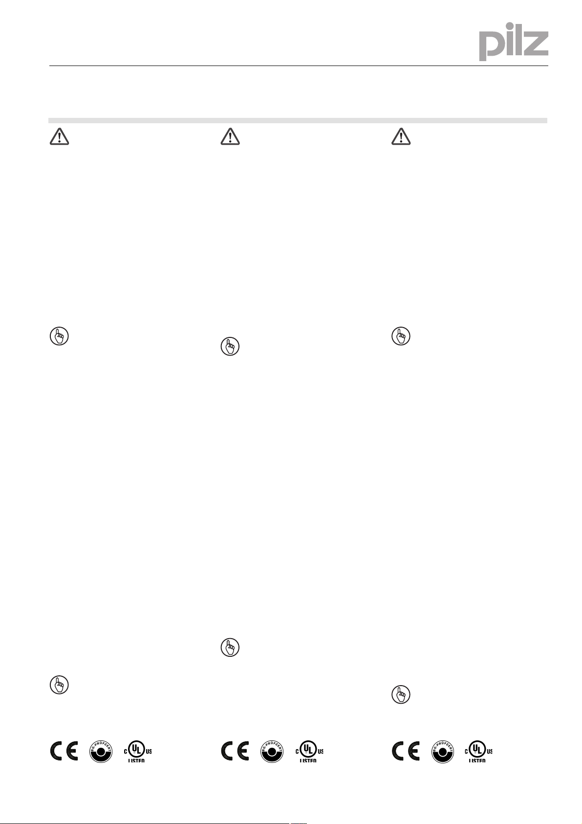
Innenschaltbild Internal wiring diagram Schéma interne
Funktionsbeschreibung
Das PSEN ix1 schaltet die angeschlossenen
Sicherheitsschalter/Positionsschalter in
Reihe.
Function description
The PSEN i1 switches the connected safety
switches /position switches in series.
Description du fonctionnement
LE PSEN ix1 assure la mise en série des
capteurs de sécurité ou des interrupteurs de
position raccordés.
Schnittstelle montieren
Achtung! Montieren Sie das Gerät in
einen Schaltschrank mit einer
Schutzart von mindestens IP54.
• Befestigen Sie das Gerät mit Hilfe des
Rastelements auf der Rückseite auf einer
Normschiene.
• Sichern Sie das Gerät auf einer senkrechten Tragschiene (35 mm) durch ein
Halteelement (z. B. Endhalter oder
Endwinkel)
Gerät in Betrieb nehmen
Betriebsbereitschaft herstellen
• Legen Sie die Versorgungspannung an:
Klemme A1: + 24 V DC
Klemme A2: 0 V
• Schließen sie die Geräte der Serie
PNOZ X, PNOZsigma, PNOZpower oder
PNOZelog an. Beachten Sie die Betriebs-
anleitung der entsprechenden Geräte.
• Verbinden Sie das PSEN ix1 mit einem
der genannten Sicherheitsschaltgeräte wie
in der folgenden Tabelle angegeben.
• Verbinden Sie die Sicherheitsschalter/
Positionsschalter mit dem PSEN ix1.
Installing the interface
Caution!The unit should be installed
in a control cabinet with a protection
type of at least IP54.
• Use the notch on the back of the unit to
attach it to a DIN rail.
• Secure the unit on a vertical DIN rail (35
mm) using a retaining bracket or end angle
Commissioning the unit
Preparing for operation
• Connect the supply voltage:
Terminal A1: + 24 V DC
Terminal A2: 0 V
• Connect the units of the PNOZ X,
PNOZsigma, PNOZpower or PNOZelog
series. Please refer to the operating
instructions for the respective unit.
• Connect the PSEN ix1 with one of the
named safety relays as shown in the
following table.
• Connect the safety switches/position
switches to the PSEN ix1.
- 2 -
Montage de l'interface
Attention ! Installez l'appareil dans
une armoire électrique ayant un
indice de protection minimum IP 54.
• Montez l'appareil sur un rail DIN à l'aide du
système de fixation situé au dos du relais.
• Fixez l'appareil sur un rail DIN vertical (35
mm) avec un élément de maintien comme
par ex. un support ou une équerre
terminale.
Mise en oeuvre
Mise en service en liaison avec
• Appliquez la tension d’alimentation :
Borne A1 : + 24 V CC
Borne A2 : 0 V
• Câblez le relais de la gamme PNOZ X,
PNOZsigma, PNOZpower ou PNOZelog.
Veuillez consulter la notice d'installation de
l'appareil utilisé.
• Câblez le PSEN ix1 à un des blocs
logiques de sécurité comme indiqué dans
le tableau ci-après.sécurité sur le
PSEN ix1.
Page 3
Wichtig: Beachten Sie beim
Anschluss von weniger als 4
Sicherheitsschaltern/Positionsschaltern an einem PSEN ix1: freie
Schließerkontakte überbrücken.
• Bei Anschluss von mehr als 4 Sicherheitsschaltern/Positionsschaltern: PNOZ ix1 in
Reihe schalten (siehe Abbildung "Reihenschaltung von PSEN). Ab dem zweiten
PSEN ix1 Y8-Y9 brücken.
Achtung! Durch elektrostatische
Entladung können Bauteile des
Geräts beschädigt werden. Sorgen
Sie für Entladung, bevor Sie das
Gerät berühren, z. B. durch
Berühren einer geerdeten, leitfähigen Fläche oder durch Tragen
eines geerdeten Armbands.
Notice: When connecting less than 4
safety switches/position switches,
please note: link out the free N/O
contacts on the PSEN ix1.
• When more than 4 safety switches/position
switches are connected: Connect PNOZ
ix1 in series (see illustration "Connecting
PSEN ix1 in series"). From the second
PSEN ix1, link Y8-Y9.
Caution! Electrostatic discharge
can damage components on the
unit. Ensure against discharge
before touching the unit, e.g. by
touching an earthed, conductive
surface or by wearing an earthed
armband.
Important : en cas de raccordement
de moins de 4 capteurs/interrupteurs:
ponter les contacts à fermeture libres
sur le PSENix1.
• En cas de raccordement de plus de 4
capteurs/interrupteurs de position : mettre
les PSEN ix1 en série ( voir exemple "Mise
en série de PSEN". Ponter les bornes
Y8-Y9 à partir du 2ème PSEN ix1.
ATTENTION ! Une décharge
électrostatique peut endommager
les éléments de l’appareil.
Avant de manipuler la carte il est
recom-mandé de se décharger en
tenant par exemple une surface
plate liée à la terre ou en s’équipant
d’un bracelet anti-statique.
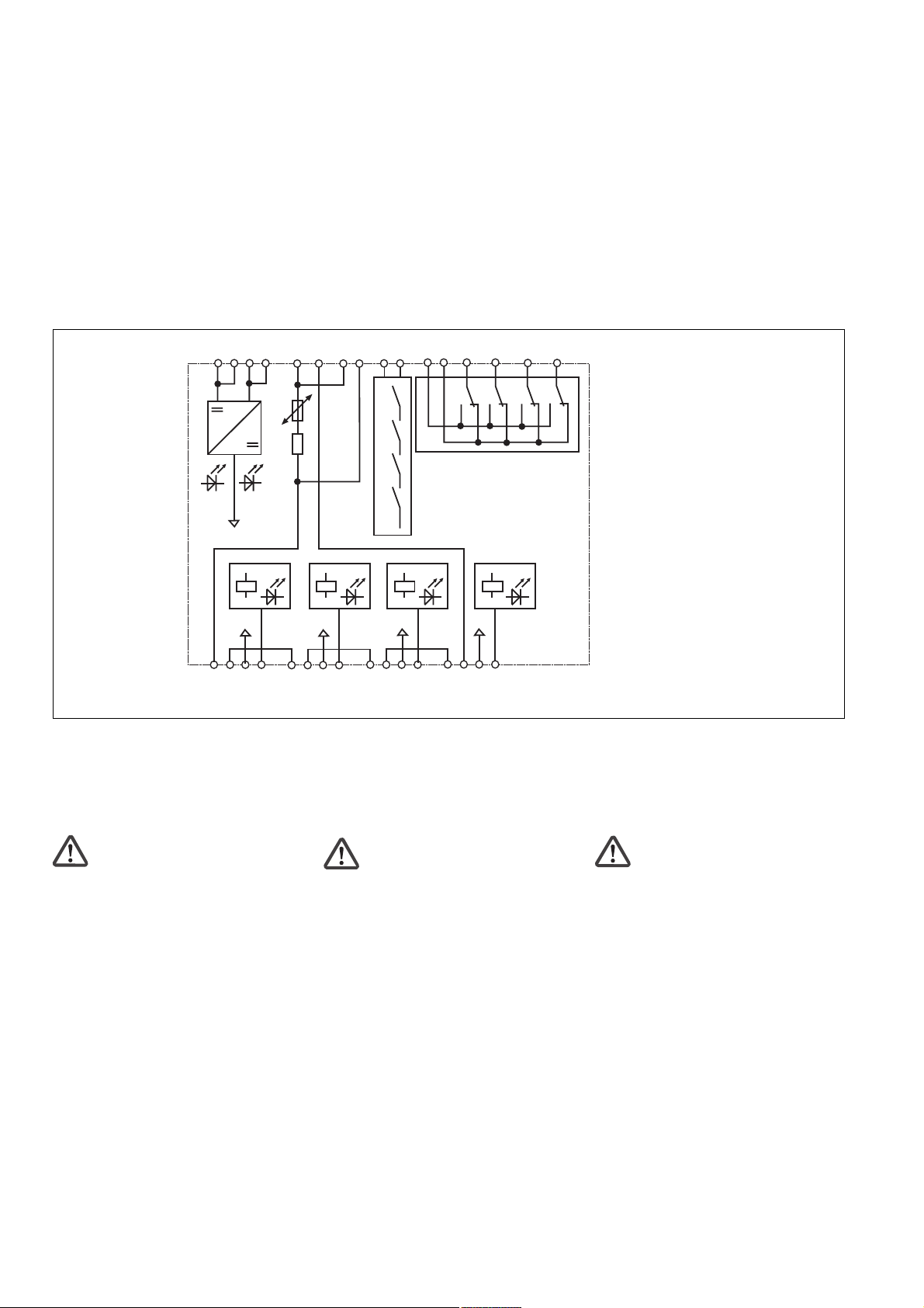
Anschluss an Auswertegerät über
Schnittstelle PSEN ix1
Achtung! An den Klemmen 13/14,
23/24, 33/34 und 43/44, darf der
Leitungswiderstand maximal
30 Ohm betragen.
• PNOZ s3
• PNOZ s4
• PNOZ s5
• PNOZ p1p
• PNOZ X2
• PNOZ X2P
• PNOZ X2.1
(nur 24 V DC)
• PNOZ X2.2
• PNOZ X2.3P
• PNOZ X2.7P
• PNOZ X2.8P
• PNOZ X2C
• PNOZ X2.1C
(nur 24 V DC)
• PNOZ X4
• PNOZ X8P
• PNOZ X9
• PNOZ X9P
• PNOZ X10
• PNOZ X10.1
• PNOZ X 10.11P
• PNOZ Ex
• PNOZ e1.1p
• PNOZ e1vp
• PNOZ e6.1p
• PNOZ e6vp
• PNOZ X2.9P
Connection to evaluation device via PSEN
ix1 interface
Caution! The cable resistance at
terminals 13/14, 23/24, 33/34 and
43/44 may be a maximum of 30
Ohm.
S21
S22
S11
S12
S11
S52
S11
S12
1
2
3
4
1
2
3
4
PSEN ix1
PSEN ix1
braun/brown/marron
11
weiß/white/blanc
12
blau/blue/bleu
13
schwarz/black/noir
14
braun/brown/marron
11
weiß/white/blanc
12
blau/blue/bleu
13
schwarz/black/noir
14
Raccordement à l'unité de contrôle via
l'interface PSEN ix1
Attention ! Sur les bornes 13/14,
23/24, 33/34 et 43/44, la résistance
du câble ne doit pas dépasser 30
Ohm.
• PSEN 1.1a-22
• PSEN 1.1b-22
1
2
3
4
• PSEN 1.1b-25
• PSEN 1.1p-12
• PSEN 1.1p-22
• PSEN 1.2p-22
• PSEN 1.2p-25
• PSEN ma 1.3a-22
• PSEN ma 1.3b-22
• PSEN ma 1.3b-25
• PSEN 1.1a-22
• PSEN 1.1b-22
1
2
3
4
• PSEN 1.1b-25
• PSEN 1.1p-12
• PSEN 1.1p-22
• PSEN 1.2p-22
• PSEN 1.2p-25
• PSEN ma 1.3a-22
• PSEN ma 1.3b-22
• PSEN ma 1.3b-25
• PNOZ X5
• PNOZ X5J
• PNOZ 11
• PNOZ 16
• PNOZ X11P
• PNOZ X13
• PNOZ X2.5P
• PNOZ X3
• PNOZ X3.1
• PNOZ X3P
• PNOZ X3.10P
• PNOZ XV2
• PNOZ XV2P
• PNOZ XV3
• PNOZ XV3P
S11
S22
S11
S12
S21
S22
S31
S32
1
2
3
4
1
2
3
4
PSEN ix1
PSEN ix1
- 3 -
braun/brown/marron
11
weiß/white/blanc
12
blau/blue/bleu
13
schwarz/black/noir
14
braun/brown/marron
11
weiß/white/blanc
12
blau/blue/bleu
13
schwarz/black/noir
14
• PSEN 1.1a-22
1
2
3
4
• PSEN 1.1b-22
• PSEN 1.1b-25
• PSEN 1.1p-12
• PSEN 1.1p-22
• PSEN 1.2p-22
• PSEN 1.2p-25
• PSEN ma 1.3a-22
• PSEN ma 1.3b-22
• PSEN ma 1.3b-25
1
2
3
4
• PSEN 1.1a-22
• PSEN 1.1b-22
• PSEN 1.1b-25
• PSEN 1.1p-12
• PSEN 1.1p-22
• PSEN 1.2p-22
• PSEN 1.2p-25
• PSEN ma 1.3a-22
• PSEN ma 1.3b-22
• PSEN ma 1.3b-25
Page 4
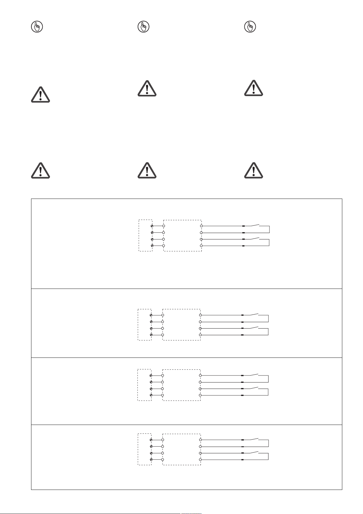
• PNOZ X6 (mit Brücke Y3-Y4)
S23
S24
S11
S12
1
2
3
4
PSEN ix1
braun/brown/marron
11
weiß/white/blanc
12
blau/blue/bleu
13
schwarz/black/noir
14
• PSEN 1.1a-22
1
2
3
4
• PSEN 1.1b-22
• PSEN 1.1b-25
• PSEN 1.1p-12
• PSEN 1.1p-22
• PSEN 1.2p-22
• PSEN 1.2p-25
• PSEN ma 1.3a-22
• PSEN ma 1.3b-22
• PSEN ma 1.3b-25
• PMUT X1P • PSEN 1.1a-22
S61
S62
S51
S52
1
2
3
4
PSEN ix1
braun/brown/marron
11
weiß/white/blanc
12
blau/blue/bleu
13
schwarz/black/noir
14
1
2
3
4
• PSEN 1.1b-22
• PSEN 1.1b-25
• PSEN 1.1p-12
• PSEN 1.1p-22
• PSEN 1.2p-22
• PSEN 1.2p-25
• PSEN ma 1.3a-22
• PSEN ma 1.3b-22
• PSEN ma 1.3b-25
• PNOZ e5.11p
A1
S12
A1
S22
1
2
3
4
PSEN ix1
braun/brown/marron
11
weiß/white/blanc
12
blau/blue/bleu
13
schwarz/black/noir
14
1
2
3
4
• PSEN 1.1a-22
• PSEN 1.1b-22
• PSEN 1.1b-25
• PSEN 1.1p-12
• PSEN 1.1p-22
• PSEN 1.2p-22
• PSEN 1.2p-25
• PSEN ma 1.3a-22
• PSEN ma 1.3b-22
• PSEN ma 1.3b-25
S1
1
2
3
4
S1
1
2
3
4
S1
1
2
3
4
S1
1
2
3
4
S1:
Not-Halt-Schalter
Emergency Stop Button
Poussoir AU
PSEN ix1
braun/brown/
11
weiß/white/blanc
12
blau/blue/bleu
13
schwarz/black/noir
14
braun/brown/
21
weiß/white/blanc
22
blau/blue/bleu
23
schwarz/black/noir
24
braun/brown/
31
weiß/white/blanc
32
blau/blue/bleu
33
schwarz/black/noir
34
braun/brown/
41
weiß/white/blanc
42
blau/blue/bleu
43
schwarz/black/noir
44
marron
marron
marron
marron
1
2
3
4
1
2
3
4
1
2
3
4
1
2
3
4
Sicherheitssensoren/
Positionsschalter
safety switches/
position switches
capteurs de sécurité/
interrupteurs de position
PSEN ix1
braun/brown/
11
weiß/white/blanc
12
blau/blue/bleu
13
schwarz/black/noir
14
braun/brown/
21
weiß/white/blanc
22
blau/blue/bleu
23
schwarz/black/noir
24
braun/brown/marron
31
weiß/white/blanc
32
blau/blue/bleu
33
schwarz/black/noir
34
braun/brown/
41
weiß/white/blanc
42
blau/blue/bleu
43
schwarz/black/noir
44
marron
marron
marron
Sicherheitsschalter/Positionsschalter/NotHalt anschließen
max. 13 PSEN ix1, Y8-Y9 ab zweitem
Gerät brücken
PNOZ X, PNOZsigma,
PNOZpower, PNOZelog
S21 S11 S21 S12
S22 S22 S22 S24
S11 S11 S31 S11
S12 S12 S32 S12
Reihenschaltung von PSEN ix1
1
2
3
4
Connecting the safety switches/position
switches/E-STOP
max. 13 PSEN ix1, link Y8-Y9 from the
second device
PSEN ix1
Y8
Y9
1
2
3
4
PSEN ix1
Connecting PSEN ix1in series
- 4 -
Raccordement des capteurs/interrupteurs
de position/poussoir d'AU
max. 13 PSEN ix1, ponter Y8-Y9 à partir du
2ème appareil
Y8
Y9
1
2
3
4
PSEN ix1
Y8
Y9
Mise en série de PSEN ix1
Page 5
PSEN ix1
Y1
Y2
Y3
Y4
Y6
Y5
S4
S3
S2
S1
L+
L-
K1
K2
K3
K4
Diagnoseausgänge beschalten:
• Beschalten Sie bei Bedarf die Diagnoseausgänge Y1 ... Y6 des PSEN ix1.
Connecting the diagnostic outputs:
• If required, connect the diagnostic outputs
Y1 ... Y6 on the PSEN i1.
Raccordement des sorties diagnostic:
• Câblez si nécessaire les sorties Y1 ... Y6
du PSEN ix1.
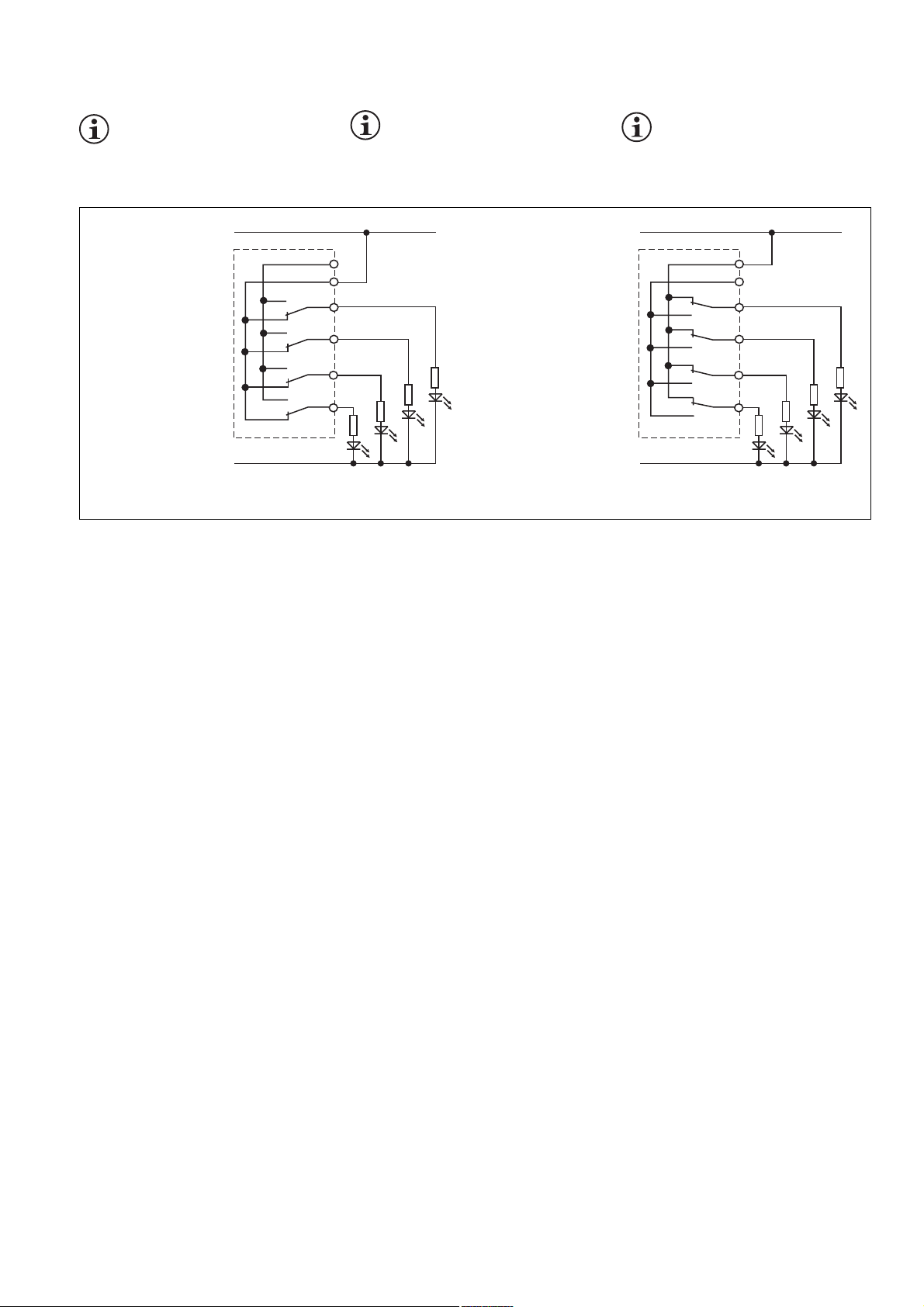
INFO: Beschalten Sie entweder Y5
oder Y6. Durch die Beschaltung von
Y5 oder Y6 legen Sie fest, ob der
Schließer- oder Öffnerkontakt
INFORMATION: Connect Y5 or Y6.
Connecting Y5 or Y6 establishes
whether the N/O or the N/C contact will
be evaluated.
INFO : Câbler soit Y5 ou Y6. Le
câblage de Y5 ou Y6 définit le type du
contact à ouverture ou à fermeture qui
est utilisé.
ausgewertet wird.
LED leuchtet bei
geöffneter Schutztür bzw.
betätigtem Not-HaltTaster
LED lights up when
safety gate is open or ESTOP is open
LEDs allumées pour
portes ouvertes ou
poussoirs AU actionnés
L+
L-
PSEN ix1
Y5
Y6
K1
Y1
K2
Y2
Y3
K3
Y4
K4
S2
S3
S4
LED leuchtet bei geschlossener Schutztür bzw. geschlossenem Not-Halt-Taster
LED lights up when safety
gate is closed or E-STOP
is closed
LEDs allumées pour portes
fermées ou poussoirs AU
non actionnés
S1
Diagnoseausgänge anschließen Connecting the diagnostic outputs Raccorder les sorties diagnostic
Betrieb
Das Gerät ist betriebsbereit, wenn die LED
"POWER" dauerhaft leuchtet.
Statusanzeigen:
•"S1" ... "S4" leuchtet: bei geöffnetem
Schließerkreis des jeweiligen zweiten
Kanals
Fehleranzeige:
• LED "FAULT" leuchtet:
Interner Fehler
Operation
The unit is ready for operation when the
"POWER" LED is lit continuously.
Status indicators:
•"S1" ... "S4" lights up: With opened N/O
output of each second channel
Fault indicator:
• LED "FAULT" light up:
Internal error
Fonctionnement
L’appareil est prêt à fonctionner lorsque la
" LED POWER " reste allumée.
Affichages d’état :
•"S1" ... "S4" s’allument : en cas de
ouverte du contact du 2ème canal
correspondant
Affichage des erreurs :
• La LED "FAULT" allumée:
défaut interne
- 5 -
Page 6

Technische Daten
Versorgungsspannung U
Spannungstoleranz
Innenwiderstand
Leistungsaufnahme bei U
ohne Last
Restwelligkeit U
B
Spannung und Strom an
Y1, Y2, Y3, Y4, Y5, Y6
Luft- und Kriechstrecken
Klimabeanspruchung
EMV
Schwingungen nach
Frequenz
Amplitude
Umgebungstemperatur
Lagertemperatur
Schutzart
Einbauraum (z. B. Schaltschrank)
Gehäuse
Klemmenbereich
Anschlussart
Querschnitt des Außenleiters
1 Leiter
flexibel
2 Leiter gleichen Querschnitts
flexibel mit Aderendhülse ohne
Kunststoffhülse
flexibel ohne Aderendhülse oder
mit TWIN-Aderendhülse
Gehäusematerial
Gehäuse
Fuß
Abmessungen H x B x T
Gewicht
B
B
Technical details
Supply voltage U
Voltage tolerance
Internal resistance
Power consumption at U
without load
Residual ripple U
Voltage and Current at
Y1, Y2, Y3, Y4, Y5, Y6
Airgap creepage
Climatic suitability
EMC
Vibration to
Frequency
Amplitude
Ambient temperature
Storage temperature
Protection type
Mounting (e.g. control cabinet)
Housing
Terminals
Connection type
Cable cross section
1 core
flexible
2 core, same cross section
flexible with crimp connectors,
without insulating sleeve
flexible without crimp connectors or
with TWIN crimp connectors
Housing material
Housing
Base
Dimensions H x W x D
Weight
B
B
B
Caractéristiques techniques
Tension d’alimentation U
Page de la tension d'alimentation
Résistance interne
Consommation pour U
sans charge
Ondulation résiduelle U
Tension, courant aux bornes
Y1, Y2, Y3, Y4, Y5, Y6
Cheminement et claquage
Sollicitations climatiques
CEM
Oscillations selon
fréquence
amplitude
Température d'utilisation
Température de stockage
Indice de protection
Lieu d’implantation (ex. armoire)
Boîtier
Borniers
Mode de raccordement
Capacité de raccordement
1 conducteur
souple
2 câbles de même diamètre
souple avec embout sans
chapeau plastique
souple sans embout ou avec
embout TWIN
Matériau du boîtier
boîtier
socle
Dimensions H x L x P
Poids
B
B
B
24 V DC
85...110%
typ. 10 Ohm
max. 1,5 W
DC: 20%
24V/500 mA
DIN VDE 0110-1, 04/97
DIN IEC 60068-2-3, 12/86
EN 60947-5-3, 05/99
EN 60068-2-6, 04/95
10...55 Hz
0,35 mm
-10...+55 °C
-25...+70 °C
IP54
IP20
IP20
Federkraftklemmen/
spring-loaded terminals/
bornes à ressorts
0,08 ... 2,5 mm
0,08 ... 1 mm
0,08 ... 1,5 mm
2
2
2
PA 6 UL 94-HB
PA 66 UL 94-V2
96 x 48 x 58 mm
(3.77" x 1.88" X 2.28")
100 g
- 6 -
Page 7
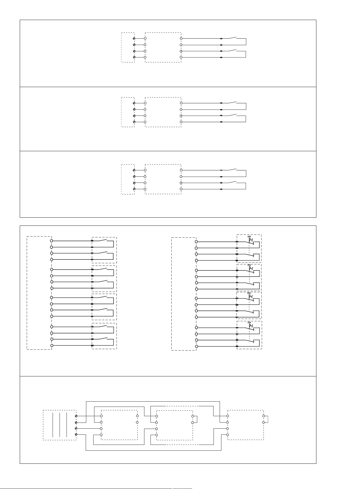
DD
D
DD
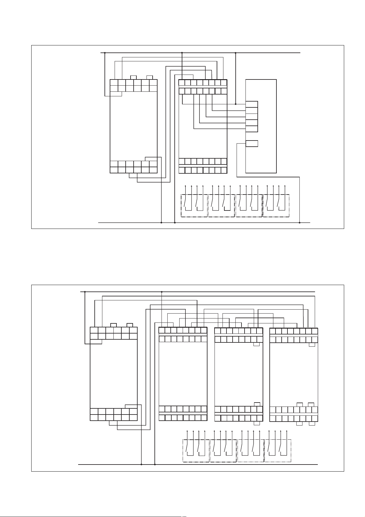
Anschlussbeispiel:
Auswertung (PNOZ X3) von 4 Sicherheitsschaltern
L+
S31S32
A1 B1
PNOZ X3
14 24
Y31 Y32 S21S22 S33 S34
GBGB
GB
GBGB
Connection example:
Evaluation (PNOZ X3) of 4 safety switches
S11
S13 S14
S12
13 23 33 41
3442B2A2
A1 A1 A2 A2 1 2
Y5 Y6 Y1 Y2 Y3 Y4 Y8 Y9
PSEN ix1
23 24
13 14
11 12
21 22
33 34
31 32
34
43 44
41 42
FF
F
FF
Exemple de raccordement :
Unité de contrôle (PNOZ X3) avec 4 capteurs
de sécurité
SPS/PLC/API
+24V
I 0.0
I 0.1
I 0.2
I 0.3
0 V
L-
DD
D
DD
Anschlussbeispiel:
Auswertung (PNOZ X3) von 9 Sicherheitsschaltern über 3 in Reihe geschaltete
PSEN ix1. Bei Reihenschaltung ab dem 2.
PSEN ix1 Y8-Y9 brücken.
L+
S11
S31S32
A1 B1
S12
13 23 33 41
111213 14 23 24 313233 34 414243 4421
1234
PSEN 1.1p-12
GBGB
GB
GBGB
Connection example:
Evaluation (PNOZ X3) of 9 safety switches
via 3 PSEN ix1 units connected in series.
When connected in series, link Y8-Y9
from the second PSEN.
S13 S14
A1 A1 A2 A2 1 2 34
Y5 Y6 Y1 Y2 Y3 Y4 Y8 Y9
22
1234
PSEN 1.1p-12
1234
PSEN 1.1p-12
Unité de contrôle (PNOZ X3) avec 9 capteurs
de sécurité câblés à l’aide de 3 PSEN ix1 en
série. Ponter Y8-Y9 à partir du 2ème
appareil en cas de mise en série.
A1 A1 A2 A2 1 2 34
Y5 Y6 Y1 Y2 Y3 Y4 Y8 Y9
1234
PSEN 1.1p-12
FF
F
FF
Exemple de raccordement :
A1 A1 A2 A2 1 2 34
Y5 Y6 Y1 Y2 Y3 Y4 Y8 Y9
PNOZ X3
14 24
Y31 Y32 S21S22 S33 S34
L-
3442B2A2
PSEN ix1
13 14
11 12
33 34
23 24
31 32
21 22
111213 14 23 24 31 32 33 34 41 42 43 4421 22
1234
PSEN 1.1p-12
- 7 -
43 44
41 42
PSEN ix1
13 14
23 24
11 12
21 22
1234
PSEN 1.1p-12
43 44
33 34
41 42
31 32
1234
PSEN 1.1p-12
PSEN ix1
13 14
23 24
11 12
21 22
1234
PSEN 1.1p-12
33 34
31 32
43 44
41 42
Page 8
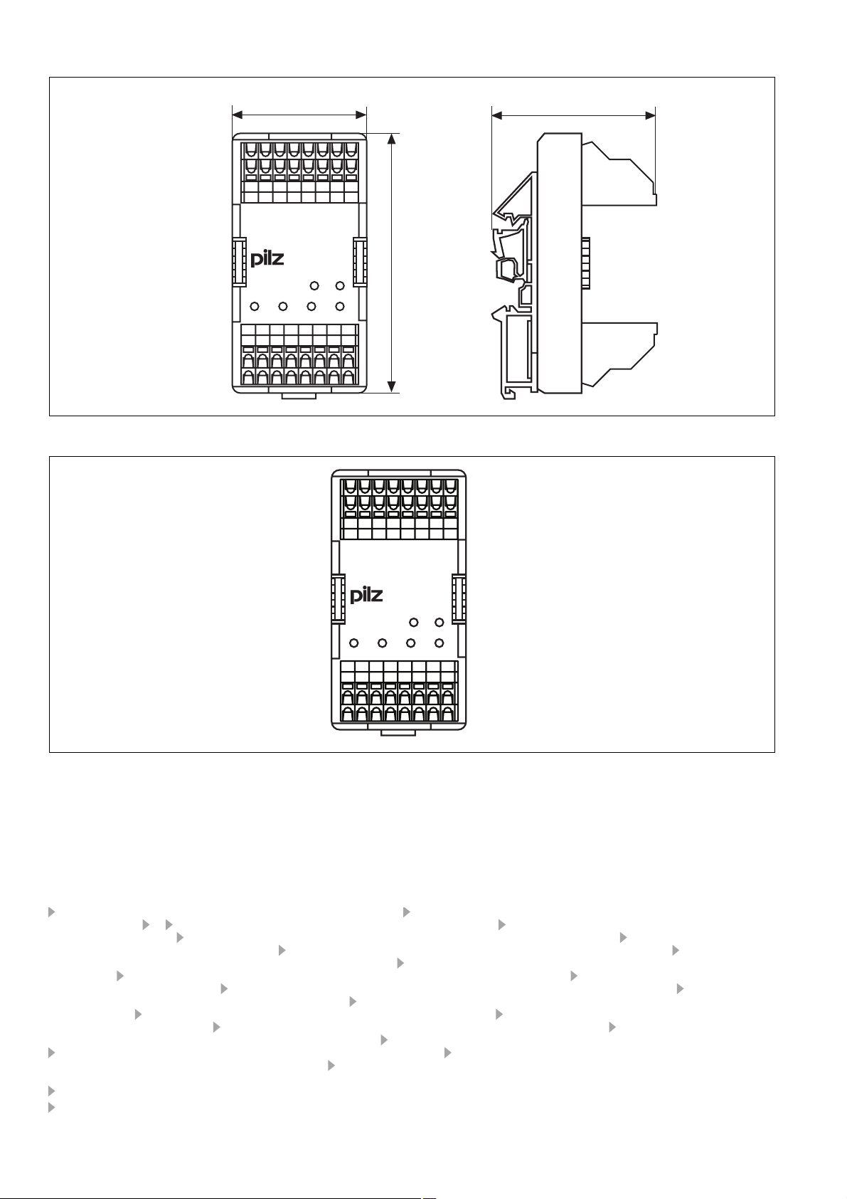
4GB Dimensions in mm (") 4F Dimensions en mm (")4D Abmessungen in mm (")
48 (1.88")
PSEN ix1
58 (2.28)
96 (3.77")
4GB Connector pin assignment 4F Affectation des raccords4D Anschlussbelegung
A2
123
A2
POWER
A1
A1
Y5 Y6 Y1 Y2 Y3 Y4 Y8 Y9
4
FAULT
PSEN ix1
S1
S2 S3 S4
24
14
23
13
12
11
A
Pilz Ges.m.b.H., ✆ 01 7986263-0, Fax: 01 7986264, E-Mail: pilz@pilz.at
safety@pilz.com.au
E-Mail: pilz@pilzbr.com.br
✆ 74436332, Fax: 74436342, E-Mail: pilz@pilz.dk
Electronic,
pilz.fi@pilz.dk
Fax: 031 789555, E-Mail: info@pilz.it
Ltd.,
✆ 045 471-2281, Fax: 045 471-2283, E-Mail: pilz@pilz.co.jp
info@mx.pilz.com
352, E-Mail: t.catterson@pilz.co.nz
Office,
✆ 021 62494658, Fax: 021 62491300,
SE
Pilz Skandinavien K/S, ✆ 0300 13990, Fax: 0300 30740, E-Mail: pilz.se@pilz.dk
✆ 0224 2360180, Fax: 0224 2360184, E-Mail: pilz.tr@pilz.de
info@pilzusa.com
www
www.pilz.com
D
Pilz GmbH & Co. KG, Sichere Automation, Felix-Wankel-Straße 2, 73760 Ostfildern, Deutschland, ✆ +49 711 3409-0, Fax: +49 711 3409-133,
E-Mail: pilz.gmbh@pilz.de
B L
Pilz Belgium, ✆ 09 3217570, Fax: 09 3217571, E-Mail: info@pilz.be
CH
Pilz lndustrieelektronik GmbH, ✆ 062 88979-30, Fax: 062 88979-40, E-Mail: pilz@pilz.ch
E
Pilz lndustrieelektronik S.L., ✆ 938497433, Fax: 938497544, E-Mail: pilz@pilz.es
✆ 03 88104000, Fax: 03 88108000, E-Mail: siege@pilz-france.fr
GB
Pilz Automation Technology, ✆ 01536 460766, Fax: 01536 460866, E-Mail: sales@pilz.co.uk
IRL
Pilz Ireland Industrial Automation, ✆ 021 4346535, Fax: 021 4804994, E-Mail: sales@pilz.ie
MEX
NL
Pilz Nederland, ✆ 0347 320477, Fax: 0347 320485, E-Mail: info@pilz.nl
P
Pilz Industrieelektronik S.L., ✆ 229407594, Fax: 229407595, E-Mail: pilz@pilz.es
E-Mail: sales@pilz.com.cn
USA
33 34
21 22
31 32
AUS
FIN
Pilz de Mexico, S. de R.L. de C.V., ✆ 55 5572 1300, Fax: 55 5572 4194, E-Mail:
ROK
Pilz Automation Safety L.P., ✆ 734 354-0272, Fax: 734 354-3355, E-Mail:
44
43
41 42
Pilz Australia, ✆ 03 95446300, Fax: 03 95446311, E-Mail:
BR
Pilz do Brasil, ✆ 11 4337-1241, Fax: 11 4337-1242,
DK
Pilz Skandinavien K/S, ✆ 09 27093700, Fax: 09 27093709, E-Mail:
NZ
Pilz Korea, ✆ 031 8159541, Fax: 031 8159542, E-Mail: info@pilzkorea.co.kr
TR
Pilz Elektronik Güvenlik Ürünleri ve Hizmetleri Tic. Ltd. ¸Sti.,
I
Pilz ltalia Srl, ✆ 031 789511,
Pilz New Zealand, ✆ 09- 6345-350, Fax: 09-6345-
PRC
Pilz China Representative
Pilz Skandinavien K/S,
F
Pilz France
J
Pilz Japan Co.,
20 950-06, 2009-04 Printed in Germany
- 8 -
 Loading...