

Page 1
22179-3FR-04
4 D Betriebsanleitung
4 GB Operating instructions
4 F Manuel d'utilisation
A1 A2
Power
12 22
Sensing
face
Damping
material
PSEN in1n
22179-3FR-04PSEN in1n
Sicherheitsschalter PSEN in1n
1240322827
Der Sicherheitsschalter erfüllt die Anforderungen nach:
EN 60204-1
EN 60947-5-2 und EN 60947-5-3: PDF-M
EN 62061: SIL CL 3
EN ISO 13849-1:2006: PL e und Kat. 4
Die Sicherheitsausgänge müssen 2-kanalig
weiterverarbeitet werden.
Safety switch PSEN in1n
The safety switch meets the requirements in
accordance with:
EN 60204-1
EN 60947-5-2 and EN 60947-5-3: PDF-M
EN 62061: SIL CL 3
EN ISO 13849-1:2006: PL e and Cat. 4
The safety outputs must use 2-channel
processing.
Capteur de sécurité PSEN in1n
La capteur de sécurité satisfait aux exigences
des normes :
EN 60204-1
EN 60947-5-2 et EN 60947-5-3 : PDF-M
EN 62061 : SIL CL 3
EN ISO 13849-1:2006 : PL e et cat. 4
Les sorties de sécurité doivent être traitées par
2 canaux.
Zu Ihrer Sicherheit
547263243
Installieren und nehmen Sie das Gerät nur
dann in Betrieb, wenn Sie diese Betriebsanleitung gelesen und verstanden haben und
Sie mit den geltenden Vorschriften über Arbeitssicherheit und Unfallverhütung vertraut
sind.
Beachten Sie die VDE- sowie die örtlichen
Vorschriften, insbesondere hinsichtlich
Schutzmaßnahmen
Durch Öffnen des Gehäuses oder eigen-
mächtige Umbauten erlischt jegliche Gewährleistung.
777809547
Entfernen Sie die Schutzkappe erst unmittel-
bar vor Anschluss des Geräts.
Gerätemerkmale
1240335115
Wirkweise: induktiv
nicht bündig einbaubar
zweikanaliger Betrieb
2 Sicherheitsausgänge
LED-Anzeige für:
– Schaltzustände
– Zustand der Eingänge
– Versorgungsspannung/Fehler
For your safety
Only install and commission the unit if you
have read and understood these operating
instructions and are familiar with the applicable regulations for health and safety at work
and accident prevention.
Ensure VDE and local regulations are met,
especially those relating to safety.
Any guarantee is rendered invalid if the hous-
ing is opened or unauthorised modifications
are carried out.
Do not remove the protective cap until you
are just about to connect the unit.
Unit features
Operation: inductive
Non-flush installation
Dual-channel operation
2 safety outputs
LED for:
–Switch states
– State of the inputs
– Supply voltage/fault
Pour votre sécurité
Vous n'installerez l'appareil et ne le mettrez
en service qu'après avoir lu et compris le
présent manuel d'utilisation et vous être familiarisé avec les prescriptions en vigueur
sur la sécurité du travail et la prévention des
accidents.
Respectez les normes locales ou VDE, particulièrement en ce qui concerne la sécurité.
L'ouverture de l'appareil ou sa modification
annule automatiquement la garantie.
Veuillez retirer le cache de protection avant
de raccorder l'appareil.
Caractéristiques de l'appareil
Actionnement : inductif
Montage avec dépassement (voir fig. page
10)
Commande par 2 canaux
2 sorties de sécurité
LEDs de visualisation :
– états de commutation
– état des entrées
– tension d'alimentation / erreurs
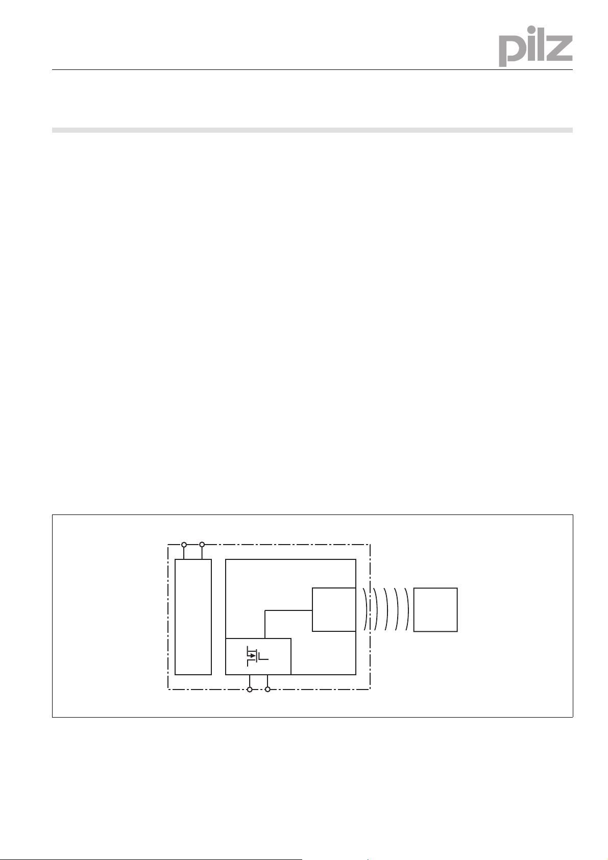
Blockschaltbild Block diagram Schéma de principe
- 1 -
Page 2
Funktionsbeschreibung
1239364491
Die Veränderung des elektromagnetischen Feldes im Ansprechbereich bewirkt eine Zustandsänderung an den Ausgängen.
Die Sicherheitsausgänge 12 und 22 leiten,
wenn
` ein dämpfender Werkstoff im Ansprechbe-
reich ist
Die Sicherheitsausgänge 12 und 22 sperren,
wenn
` ein dämpfender Werkstoff sich außerhalb
des Ansprechbereichs befindet
Function description
If the electromagnetic field changes within the
response range, the outputs will change state.
Safety outputs 12 and 22 conduct when
` Damping material is within the response
range
Safety outputs 12 and 22 are disabled when
` Damping material is outside the response
range
Description du fonctionnement
La modification du champ électromagnétique
dans la zone de détection provoque un changement de l'état des sorties.
Les sorties de sécurité 12 et 22 sont sous tension si
` un matériau amortissant se trouve dans la
zone de détection
Les sorties de sécurité 12 et 22 sont verrouillées si :
` un matériau amortissant se t rouve en de hors
de la zone de détection
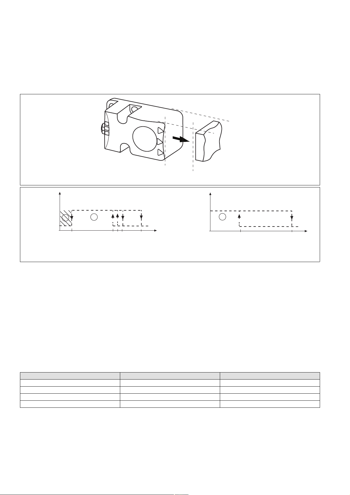
Schaltabstände Operating distances Distances de commutation
Aktive Schaltfläche PSEN ini/Sensing face PSEN ini/Surface active du PSEN ini
Ua
Ein/On/Marche
2
s
ao
Aus/Off/Arrêt
Legende
1240441099
1
s
l
Bei ferromagnetischen Metallen/
With ferromagnetic metals/
Avec des métaux ferromagnétiques
` c: Sperrbereich (nur bei ferromagnetischen
Metallen)
` d: Ansprechbereich
` Sl: typischer Sperrabstand
` Sao: gesicherter Schaltabstand
` So: typischer Schaltabstand
` Sr: typischer Ausschaltabstand
` Sar: gesicherter Ausschaltabstand: 45 mm
Ein/On/Marche
Aus/Off/Arrêt
S
s
s
o
r
Key
(mm)
s
ar
` c: Latched zone (only with ferromagnetic
metals)
` d: Response range
` Sl: Typical latching distance
` Sao: Assured operating distance
` So: Typical operating distance
` Sr: Typical release distance
` Sar: Assured release distance: 45 mm
Ua
2
s
o
Bei nicht ferromagnetischen Metallen/
With non-ferromagnetic metals/
Avec des métaux non ferromagnétiques
Légende
` c: zone de blocage (uniquement avec des
métaux ferromagnétiques)
` d: zone de détection
` Sl : distance de blocage caractéristique
` Sao : distance de commutation de sécurité
` So : distance de commutation caractéristi-
que
` Sr : distance de déclenchement caractéristi-
que
` Sar : distance de déclenchement de sécurité
Ansprechbereiche
1239370251
Die Grenzen der Ansprechbereiche wurden mit
einer Normmessplatte nach 60947-5-2 von
45x45x1 mm bei einer Umgebungstemperatur
von 20 °C und einem nicht bündigem Einbau
ermittelt.
Material Typischer Sperrabstand Sl Typischer Schaltabstand So
Stahl (ST37/ST1203 1.0330) 5,0 mm 15,0 mm
Edelstahl (1.4301) 4,0 mm 13,0 mm
Aluminiumlegierung (AlMg3hh) - - 6,0 mm
Kupfer (Cu) - - 4,0 mm
Response ranges
The limits of the response ranges have been
calculated using a standard measuring plate of
45x45x1 mm in accorance with 60947-5-2, at
an ambient temperature of 20 °C and with nonflush installation.
: 45 mm
Zones de détection
Les limites des zones de détection ont été déterminées à l'aide d'un gabarit normalisé selon
0947-5-2 de 45 x 45 x 1 mm avec une température de service de 20 °C et un montage avec
dépassement.
S
(mm)
s
ar
- 2 -
Page 3
1232909323
Bitte beachten Sie:
` bei Verwendung eines Bedämpfungsmateri-
als von ≤ 35x35x1 mm, verkleinern sich die
Schaltabstände stark.
1142438027
` bei Verwendung von ferromagnetischen Me-
tallen gibt es einen Sperrbereich in der Nähe
der aktiven Fläche des Sensors:
– Befindet sich das dämpfende Material län-
ger als 1 s im Sperrbereich, dann schalten
die Ausgänge ab und der Sensor wird gesperrt.
– Zum Entsperren des Sensors muss das
dämpfende Material von dem Sperrbereich weg und über den gesicherten Ausschaltabstand Sar für mindestens 1 s
hinaus verschoben werden.
Verdrahtung
517049611
Beachten Sie:
` Angaben im Abschnitt „Technische Daten“
unbedingt einhalten.
` Berechnung der max. Leitungslänge I
Eingangskreis:
R
lmax
=
I
max
Rl / km
= max. Gesamtleitungswiderstand
R
lmax
(s. techn. Daten)
R
/ km = Leitungswiderstand/km
l
max
im
Please note:
` If damping material ≤ 35x35x1 mm is used,
the operating distances will be significantly
reduced.
` If ferromagnetic metals are used, there will
be a latched zone close to the sensor's sensing face:
– If the damping material is in the latched
zone for longer than 1 s, the outputs
switch off and the sensor is latched.
– To unlatch the sensor, the damping mate-
rial must be out of the latched zone and
have moved beyond the assured release
distance Sar for at least 1 s.
Wiring
Please note:
` Information given in the “Technical details”
must be followed.
` Calculation of the max. cable length l
the input circuit:
R
lmax
=
I
max
Rl / km
= max. overall cable resistance (see
R
lmax
Technical details)
R
/ km = cable resistance/km
l
max
in
Tenez compte de ce qui suit :
` en cas d'utilisation d'un matériau amortis-
sant de ≤ 35x35x1 mm, les distances de com-
mutation se réduisent fortement.
` en cas d'utilisation de métaux ferromagnéti-
ques, il existe une zone de blocage à proximité de la surface active du capteur :
– Si le matériau amortissant se trouve plus
d'une seconde dans la zone de blocage,
les sorties sont coupées et le capteur est
bloqué.
– Pour débloquer le capteur, le matériau
amortissant doit être retiré de la zone de
blocage et placé au-delà de la distance de
déclenchement de sécurité Sar pendant
au moins 1 s.
Raccordement
Important :
` Respectez impérativement les données indi-
quées dans la partie "Caractéristiques techniques".
` Calcul de la longueur de câble max. I
le circuit d'entrée :
R
lmax
=
I
max
Rl / km
= résistance max. de l'ensemble du
R
lmax
câblage (voir les caractéristiques techniques)
/ km = résistance du câblage/km
R
l
max
sur
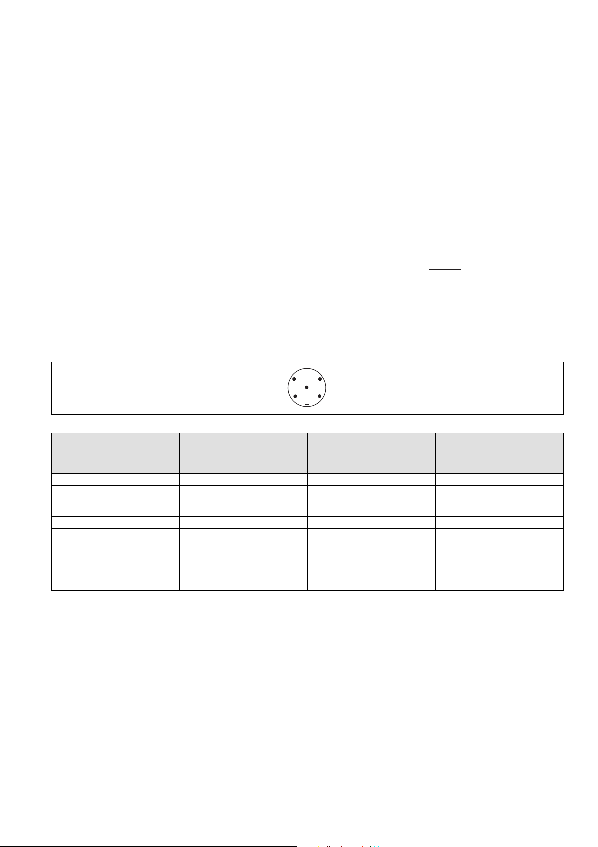
Anschlüsse Connections Raccordements
Stiftstecker 5-pol. M12 (male) Connector 5-pin M12 (male) Connecteur mâle M12 à 5 broches
4
1
Anschlussbelegung Stecker und Kabel Pin assignment, connector and cable Affectation des bornes - connecteur et câble
Anschlussbezeichnung im
Blockschaltbild/
Terminal designation/
Funktion/
Function/
Foncion
Désignation des bornes
A1 +24 UB 1 braun/brown/marron
12 Ausgang Kanal 1/
Output, channel 1/
Canal de sortie 1
A2 0 V UB 3 blau/blue/bleu
22 Ausgang Kanal 2/
Output, channel 2/
Canal de sortie 2
- nicht anschließen/
do not connect/
pas raccordé
3
5
2
PIN/
Broche
Adernfarbe (Pilz Kabel)/
Cable colour (Cable Pilz)/
Couleur du fil (fil de Pilz)
2 weiß/white/blanc
4 schwarz/black/noir
5 grau/grey/gris
- 3 -
Page 4
Anschluss an Auswertegeräte
1104750091
Bitte beachten Sie:
` das Netzteil muss den Vorschriften für Klein-
spannungen mit sicherer Trennung (SELV,
PELV) entsprechen.
` die Ein- und Ausgänge des Sicherheitsschal-
ters müssen eine sichere Trennung zu Spannungen über 60 V AC besitzen.
1289386891
` die Versorgungsspannung des Sicherheits-
schalters muss mit einer Sicherung vom Typ
Flink zwischen 2 A und 4 A abgesichert werden.
1090417163
ACHTUNG!
Die Sicherheitsausgänge müssen 2-ka-
nalig weiterverarbeitet werden.
1067372427
INFO
Sicherheitsschaltgeräte mit Weitspannungsnetzteil oder in der Geräte-Variante
(AC) haben eine interne Potentialtrennung
und sind als Auswertegeräte nicht geeignet.
Connection to evaluation devices
Please note:
` The power supply must meet the regulations
for extra low voltages with safe separation
(SELV, PELV).
` the inputs and outputs of the safety switch
must have a safe separation to voltages over
60 V AC.
` The supply voltage to the safety switch must
be protected with a 2 A to 4 A quick-acting
fuse.
CAUTION!
The safety outputs must use 2-channel
processing.
INFORMATION
AC versions of safety relays or safety relays
with a universal power supply have internal
potential isolation and are unsuitable as
evaluation devices.
Raccordement aux appareils de contrôle
Tenez compte de ce qui suit :
` Cette alimentation doit être conforme aux
prescriptions relatives aux basses tensions à
séparation galvanique (SELV, PELV).
` Les entrées et les sorties du capteur de sé-
curité doivent posséder une séparation galvanique pour les tensions supérieures à
60 V AC.
` La tension d'alimentation du capteur de sé-
curité doit être protégée à l'aide d'un fusible
de type rapide entre 2 A et 4 A.
ATTENTION !
Les sorties de sécurité doivent être trai-
tées par 2 canaux.
INFORMATION
Les capteurs de sécurité avec alimentation
universelle ou dans le modèle appareil (AC)
disposent d'une séparation de potentiel interne et ne sont pas adaptés comme appareils de contrôle.
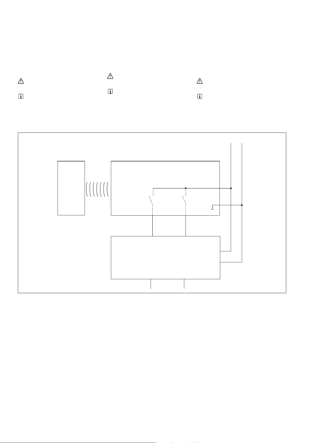
` Einzelschaltung ` Single connection ` Montage simple
24 V
0 V
Damping
material
FS: Fail-safe
ST: Standard
PSEN in1n
12 22
I1 (FS)
I2 (FS)
Auswertegerät/
Evaluation device/
Appareil de surveillance
A1
A2
A1
A2
- 4 -
Page 5

Anschlussbeispiele Connection examples Exemples de raccordements
Anschluss an PDP67 Connection to PDP67 Raccordement à PDP67
PDP67
0 V
1
3
2
4
5
Test Pulse X / 24 V DC
PDP67 F 8DI ION
Input X
Input X + 1
Test Pulse X + 1 / 24 V DC
Anschluss an PNOZmulti Connection to PNOZmulti Raccordement au PNOZmulti
Schutztür/safety gate/protecteur mobile
Schaltertyp 3/switch type 3/type du capteur 3
I0, I1: Eingänge OSSD/inputs OSSD/entrées OSSD
weiß/white/blanc
schwarz/black/noir
Anschluss an PSS Connection to PSS Raccordement au PSS
Schutztür/safety gate/protecteur mobile
Standardbaustein SB64/standard block SB64/bloc standard SB64
I00, I01: Eingänge OSSD/inputs OSSD/entrées OSSD
weiß/white/blanc
schwarz/black/noir
PSENin1n
A1
1
3
A2
2
12
4
22
5
n.c.
Montage
1279718411
ACHTUNG!
Der induktive Sicherheitsschalter kann
durch elektrisch oder magnetisch leitfähiges Material in seiner Umgebung bedämpft
werden. Als Folge davon kann es zu einer
Veränderung der Schaltabstände kommen.
Beachten Sie daher unbedingt die folgenden Anweisungen.
Beachten Sie die Einbau- und Umweltbedin-
gungen.
Stellen Sie durch geeignete konstruktive
Maßnahmen sicher, dass kein bedämpfendes Material wie z. B. Metalle in Form von
Spänen, Schrauben, Blechen usw. in die
Nähe des Sicherheitsschalters gelangen
kann.
Berücksichtigen Sie bei der Montage die An-
forderungen der DIN EN 1088.
Prüfen Sie die Schaltabstände unter realen
Bedingungen.
Prüfen Sie die Schaltabstände regelmäßig.
Prüfen Sie die Schaltabstände nach einer je-
den Änderung der Applikation.
Befestigen Sie den Sicherheitsschalter aus-
schließlich mit Schrauben M4 mit flacher
Kopfunterseite (z. B. M4-Zylinderkopf- oder Flachkopfschrauben).
Anzugsdrehmoment max. 1 Nm.
Sicherheitsschalter
keinen starken Magnetfeldern aussetzen
keinen starken Stößen oder Schwingungen
aussetzen
nicht als Anschlag benutzen
nur für feste Verkabelung
INFO
Für die Überwachung von beweglichen,
trennenden Schutzeinrichtungen empfehlen wir die Sicherheitsschalter PSENmag
und PSENc
s.
Installation
CAUTION!
The inductive safety switch may be
damped by the presence of electrically or
magnetically conductive material in its environment. The operating distances may be
changed as a result. For this reason you
must follow the instructions below.
Be aware of the installation and environmen-
tal conditions.
Appropriate design measures should be
used to ensure that no damping material, for
example metal in the form of swarf, screws,
plates, etc, can reach the vicinity of the safety switch.
When installing make sure you comply with
the requirements of DIN EN 1088.
Check the operating distances under real
conditions.
Check the operating distances regularly.
Check the operating distances each time the
application is modified.
Safety switches should only be secured us-
ing M4 screws with a flat head (e.g. M4
cheese-head or pan head screws).
Torque setting max. 1 Nm.
Safety switch
Should not be exposed to strong magnetic
fields
Should not be exposed to heavy shock or vi-
bration
Should not be used as a limit stop
Should be used for fixed wiring only
INFORMATION
For monitoring movable guards we recommend the safety switches PSENmag and
PSENcs.
Montage
ATTENTION !
Le capteur inductif de sécurité peut être
amorti dans son environnement électrique
ou magnétique. Cela peut avoir pour conséquence une modification des distances
de commutation. De ce fait, vous devez absolument respecter les instructions suivantes.
Tenez compte des conditions de montage et
d'environnement.
En prenant des mesures appropriées et
constructives, assurez-vous qu'aucun matériau amortissant, comme, par exemple, des
métaux sous forme de copeaux, vis, plaques, etc., ne se trouvent à proximité du capteur de sécurité.
Lors du montage, veuillez tenir compte des
exigences de la norme DIN EN 1088.
Vérifiez les distances de commutation en si-
tuation réelle.
Vérifiez régulièrement les distances de com-
mutation.
Vérifiez les distances de commutation après
toute modification dans l'application.
Pour fixer le capteur de sécurité, utilisez uni-
quement des vis M4 dont la tête présente
une face inférieure plate (exemple : vis M4
cylindriques ou à tête plate).
Couple de serrage max. 1 Nm.
Capteurs de sécurité
ne doivent pas être exposés à des champs
magnétiques élevés
ne doivent pas subir des chocs et vibrations
importants
ne doivent pas être utilisés comme butée
ne doivent être utilisés que dans un câblage
fixe
INFORMATION
Pour la surveillance de protecteurs mobiles, nous recommandons l'utilisation des
capteurs de sécurité PSENmag et PSENcs.
- 5 -
Page 6

Einbaubedingungen (Mindestabstände in
mm)
1139518475
` Nicht bündiger Einbau nach EN 60947-5-2,
Typ I2C40
in ferromagnetischen Metallen/in ferromagnetic metals/en métaux ferromagnétiques
Installation conditions (minimum distances
in mm)
` Non-flush installation in accordance with
EN 60947-5-2, Type I2C40
Contraintes pour le montage (distances minimales en mm)
` Montage avec dépassement selon l'EN
60947-5-2, type I2C40
40
40
40
20
30
in nicht ferromagnetischen Metallen/in non-ferromagnetic metals/en métaux non ferromagnétiques
20
20
20
10
30
Abstände zwischen Sicherheitsschaltern/Distances between safety switches/
distance entre les capteurs de sécurité
120
100
Anwendungsbeispiel Application example Exemple d'application
Positionsüberwachung
1240512267
Der Sicherheitsschalter kann zur sicheren Positionsüberwachung an Nocken und langen Nokken oder als Impulsgeber für Zählaufgaben
verwendet werden.
Beachten Sie bitte:
` die Ansprechbereiche in Abhängigkeit von
der Art des Bedämpfungsmaterials und seiner Größe (siehe "Ansprechbereiche")
und
` die Einbaubedingungen des Sicherheits-
schalters (siehe Montage)
Position monitoring
The safety switch can be used for safe position
monitoring on cams and long cams or as a
pulse generator for counting tasks.
Please note:
` The response ranges, based on the type and
size of the damping material (see "Response
ranges")
and
` The installation conditions for the safety
switch (see Installation)
Surveillance de la position
Le capteur de sécurité peut être utilisé pour la
surveillance en toute sécuité de la position des
cames et des longues cames ou en tant que
générateurs d'impulsions pour les tâches de
comptage.
Veuillez tenir compte de ce qui suit :
` les zones de détection en fonction du type
de matériau amortissant et de sa taille (voir «
Zones de détection »)
et
` les contraintes pour le montage du capteur
de sécurité (voir le montage)
- 6 -
Page 7

Betrieb
IIV
III
II
V
1239374219
Prüfen Sie vor der Inbetriebnahme die Funktion
des Sicherheitsschalters:
bedämpfen Sie den Sicherheitsschalter im
Sperrbereich (siehe Schaltabstände) mit einem ferromagnetischen Metall bis die LED
"Safety Gate" blinkt.
verschieben Sie das ferromagnetische Metall
mindestens bis zum gesicherten Ausschaltabstand S
te" erlöschen.
Dabei muss die LED "Safety Ga-
ar.
Wenn die LED "Safety Gate" nicht erlischt,
dann prüfen Sie den korrekten Einbau des
Sicherheitsschalters. Beachten Sie den Ab-
schnitt "Einbaubedingungen".
Beachten Sie, dass Flüssigkeiten oder kleinste
Festkörper auf und nahe der aktiven Fläche
während des Betriebs zu Störungen führen
können. Abhilfe: Sensor reinigen und Versorgungsspannung aus- und wieder einschalten.
1278413707
Statusanzeigen:
LED "POWER/Fault" leuchtet grün und LED
"Input" leuchtet gelb: Gerät ist betriebsbereit
LED "Safety Gate" leuchtet gelb: der dämp-
fende Werkstoff befindet sich im Ansprech-
bereich
1278420363
Fehleranzeige:
LED "Safety Gate" blinkt gelb: der Sensor
wurde zu lange im Sperrbereich mit einem
metallischen Werkstoff bedämpft. Abhilfe:
den metallischen Werkstoff aus dem Sperr-
bereich entfernen.
LED "POWER/Fault" leuchtet rot: Fehlermel-
dung.
An den LEDs "Safety Gate" und "Input" wer-
den Blinkcodes zur Fehlerdiagnose ausge-
geben (siehe unten).
Abhilfe: Fehler beheben und Stromversor-
gung unterbrechen.
1240470923
Fehlerzustände werden durch Blinken der
Leuchtdioden angezeigt. Es gibt Fehler bei denen sich aus der Anzahl der Blinkimpulse ein
Fehlercode ermitteln lässt.
Diese Fehler werden immer durch 3-maliges
kurzes Blinken der LED "Input" oder "Safetygate" angekündigt. Nach einer längeren Pause
blinkt die LED dann im Sekundentakt. Die Anzahl des Aufleuchtens der LED entspricht einer
Ziffer im Fehlercode. Der Fehlercode kann aus
bis zu 4 Ziffern bestehen. Die Ziffern sind durch
eine längere Dunkelpause voneinander getrennt. Die gesamte Sequenz wird laufend wiederholt.
1380451083
Beispiel:
Fehlercode 1,4,1:
Die LED "Safetygate" oder "Input" blinkt
3-mal kurz
Pause
1-mal für je eine Sekunde
Pause
4-mal für je eine Sekunde
Pause
1-mal für je eine Sekunde
3-mal kurz
Operation
Check the function of the safety switch before
commissioning:
Use a ferromagnetic metal to energise the
safety switch within the latched zone (see
Operating distances) until the "Safety Gate"
LED flashes.
Move the ferromagnetic metal at least as far
as the assured release distance S
"Safety Gate" LED should now go out.
ar.
The
If the "Safety Gate" LED does not go out,
check that the safety switch is installed correctly. Refer to the section entitled "Installa-
tion conditions".
Please note that fluids or the smallest amount
of solids on or near the sensing face during operation can lead to errors. Clean the sensor and
switch the supply voltage off and then on again.
Status indicators:
"POWER/Fault" LED lights up green and "In-
put" LED lights up yellow: The unit is ready
for operation
"Safety Gate" LED lights up yellow: The
damping material is within the response
range
Fault indicator:
"Safety Gate" LED flashes yellow: The sen-
sor was energised with a metallic material for
too long within the latched zone. Remedy:
Remove the metallic material from the
latched zone.
"POWER/Fault" LED lights up red: Error
message.
Flashing codes for fault diagnostics are out-
put to the "Safety Gate" and "Input" LEDs
(see below).
Remedy: Rectify fault and interrupt power
supply.
Fault conditions are indicated by flashing the
LEDs. Some errors are displayed through periodic flashing (see table); with other errors it is
possible to establish an error code through the
number of flashes.
These errors are always indicated by three
short flashes of the "Input" or "Safetygate"
LED. After a longer pause, the LED will then
flash at one second intervals. The number of
LED flashes corresponds to a digit in the error
code. The error code can consist of up to 4 digits. The digits are separated by a longer period
without flashing. The entire sequence is constantly repeated.
Example:
Error code 1,4,1:
"Safetygate" or "Input" LED flashes
3 times, briefly
Pause
Once for one second
Pause
4 times, for one second each
Pause
Once for one second
3 times, briefly
Utilisation
Vérifiez le fonctionnement du capteur de sécurité avant sa mise en service :
amortissez le capteur de sécurité dans la
zone de blocage (voir les distances de commutation) avec un métal ferromagnétique
jusqu'à ce que la LED « Safety Gate » clignote.
déplacez le métal ferromagnétique au moins
jusqu'à la distance de déclenchement de sécurité S
dre.
La LED « Safety Gate » doit s'étein-
ar.
Si la LED « Safety Gate » ne s'éteint pas, vé-
rifiez que le capteur a été monté correctement. Tenez compte du paragraphe «
Contraintes pour le montage ».
Veuillez noter que des projections de liquides
ou de particules solides minuscules qui entreraient en contact avec la surface active ou se
situeraient à sa proximité peuvent entraîner des
dysfonctionnements en cours d'utilisation. Remède : nettoyer le capteur et débrancher et rebrancher la tension d'alimentation.
Affichages des états :
La LED « POWER/Fault » s'allume en vert et
la LED « Input » s'allume en jaune : l'appareil
est prêt à fonctionner
La LED « Safety Gate » s'allume en jaune : le
matériau amortissant se situe dans la zone
de détection
Affichage des erreurs :
La LED « Safety Gate » clignote en jaune : un
matériau amortissant est présent trop long-
temps dans la zone de blocage du capteur.
Remède : retirer le matériau métallique de la
zone de blocage.
La LED « POWER/Fault » s'allume en rouge :
message d'erreur.
Des codes clignotants servant au diagnostic
des erreurs sont émis par les LEDs « Safety
Gate » et « Input » (voir ci-dessous).
Remède : éliminer le défaut et couper l'ali-
mentation électrique.
Les états d'erreur sont indiqués par le clignotement des LEDs. Certaines erreurs sont indiquées par un clignotement périodique (voir
tableau) et d'autres erreurs pour lesquelles un
code d'erreur peut être déterminé en fonction
du nombre d'impulsions clignotantes.
Pour annoncer ces erreurs, la LED „Input“ ou
„Safetygate“ clignote toujours trois fois rapidement. Après une longue pause, la LED clignote
alors toutes les secondes. Le nombre de fois où
la LED s'allume correspond à un chiffre dans le
code d'erreur. Le code d'erreur peut se composer de 4 chiffres. Les chiffres sont séparés les
uns des autres par une pause plus longue, pendant laquelle la LED ne s'allume pas. La séquence complète est répétée en continu.
Exemple :
Code d'erreur 1,4, 1 :
La LED « Safety Gate » ou « Input » clignote
3 fois rapidement
Pause
1 fois pendant une seconde à chaque fois
Pause
4 fois pendant une seconde à chaque fois
Pause
1 fois pendant une seconde à chaque fois
3 fois rapidement
1406525451
I Code für Fehlermeldung
II Code für 1. Ziffer
III Code für 2. Ziffer
IV Code für 3. Ziffer
V Wiederholung Code für Fehlermeldung
I Code for error message
II Code for 1st digit
III Code for 2nd digit
IV Code for 3rd digit
V Code for error message repeated
Code I pour message d'erreur
Code II pour le 1er chiffre
Code III pour le 2ème chiffre
Code IV pour le 3ème chiffre
Répétition du code V pour le message d'erreur
- 7 -
Page 8

Fehlercode
dezimal
1,4,1 3x kurz – 1x lang – 4x lang –
1,12 3x kurz – 1x lang – 12 x lang
1,6,3 3x kurz – 1x lang – 6x lang –
1,13 3x kurz – 1x lang – 13 x lang
14 3x kurz – 14x lang – 3x kurz Im Betrieb Kurzschluss zwischen dem Sicherheits-
15 3x kurz – 15x lang – 3x kurz Im Betrieb Kurzschluss zwischen dem Sicherheits-
1,4,2 3x kurz – 1x lang – 4x lang –
Error code
decimal
1,4,1 3x short – 1x long – 4x long –
1,12 3x short – 1x long – 12x long
1,6,3 3x short – 1x long – 6x long –
1,13 3x short – 1x long – 13x long
14 3x short – 14x long – 3x short During operation, short circuit between safety output
15 3x short – 15x long – 3x short During operation, short circuit between safety output
1,4,2 3x short – 1x long – 4x long –
Code d'erreur
décimal
Anzahl der Blinkimpulse Beschreibung Abhilfe
1x lang – 3x kurz
– 3x kurz
3x lang – 3x kurz
– 3x kurz
2x lang – 3x kurz
Number of flashes Description Remedy
1x long – 3x short
– 3x short
3x long – 3x short
– 3x short
2x long – 3x short
Nombre d'impulsions clignotantes
Im Systemhochlauf ist mindestens einer der beiden
Sicherheitsausgänge 12 und 22 nicht spannungsfrei
Im Betrieb Kurzschluss zwischen dem Sicherheitsausgang 12 und 0 V DC
Im Betrieb Kurzschluss zwischen dem Sicherheitsausgang 12 und 0 V DC
Im Betrieb Kurzschluss zwischen dem Sicherheitsausgang 22 und 0 V DC
ausgang 12 und 24 V DC
ausgang 22 und 24 V DC
Im Betrieb Kurzschluss zwischen dem Sicherheits-
ausgang 22 und 24 V DC
At least one of the two safety outputs 12 and 22 have
voltage applied during system run-up
During operation, short circuit between safety output
12 and 0 VDC
During operation, short circuit between safety output
12 and 0 VDC
During operation, short circuit between safety output
22 and 0 VDC
12 and 24 VDC
22 and 24 VDC
During operation, short circuit between safety output
22 and 24 VDC
Description Remède
Verdrahtung der Klemmen 12 und 22
prüfen, Verdrahtungsfehler beheben
Verdrahtungsfehler an Klemme 12
beseitigen
Verdrahtungsfehler an Klemme 12
beseitigen
Verdrahtungsfehler an Klemme 22
beseitigen
Verdrahtungsfehler an Klemme 12
beseitigen
Verdrahtungsfehler an Klemme 22
beseitigen
Verdrahtungsfehler an Klemme 22
beseitigen
Check the wiring of terminals 12 and
22, rectify the wiring error
Rectify wiring error at terminal 12
Rectify wiring error at terminal 12
Rectify wiring error at terminal 22
Rectify wiring error at terminal 12
Rectify wiring error at terminal 22
Rectify wiring error at terminal 22
1,4,1 3 x court – 1 x long – 4 x long
– 1 x long – 3 x court
1,12 3 x court – 1 x long – 12 x
long – 3 x court
1,6,3 3 x court – 1 x long – 6 x long
– 3 x long – 3 x court
1,13 3 x court – 1 x long – 13 x
long – 3 x court
14 3 x court – 14 x long – 3 x
court
15 3 x court – 15 x long – 3 x
court
1,4,2 3 x court – 1 x long – 4 x long
– 2 x long – 3 x court
Au démarrage du système, au moins une des sorties
de sécurité 12 et 22 n'est pas libre de potentiel
En fonctionnement, court-circuit entre la sortie de
sécurité 12 et le 0 V DC
En fonctionnement, court-circuit entre la sortie de
sécurité 12 et le 0 V DC
En fonctionnement, court-circuit entre la sortie de
sécurité 22 et le 0 V DC
En fonctionnement, court-circuit entre la sortie de
sécurité 12 et le 24 V DC
En fonctionnement, court-circuit entre la sortie de
sécurité 22 et le 24 V DC
En fonctionnement, court-circuit entre la sortie de
sécurité 22 et le 24 V DC
Vérifier le câblage des bornes 12 et
22, supprimer le défaut de câblage
Supprimer le défaut de câblage sur la
borne 12
Supprimer le défaut de câblage sur la
borne 12
Supprimer le défaut de câblage sur la
borne 22
Supprimer le défaut de câblage sur la
borne 12
Supprimer le défaut de câblage sur la
borne 22
Supprimer le défaut de câblage sur la
borne 22
- 8 -
Page 9

Abmessungen Dimensions Dimensions
61
0
2
0
2
5,1
21,5
45
72
0
4
40
12
Mx1
5
,
1
5
0
3
74
Technische Daten Technical details Caractéristiques techniques
Elektrische Daten Electrical data Données électriques
Versorgungsspannung UBDC Supply voltage UB DC Tension d'alimentation UBDC 24 V SELV/PELV
Spannungstoleranz Voltage tolerance Plage de la tension d'alimentation -20 %/+20 %
Leistungsaufnahme bei U
Kleinster Betriebsstrom (I
Leerlaufstrom (I
) No-load current (I0) Courant en fonctionnement à vide
0
DC Power consumption at UB DC Consommation UBDC 1,5 W
B
) Smallest operating current (Im) Courant de service le plus faible (Im) 5,00 mA
m
15 mA
)
(I
0
Max. Einschaltstromimpuls Max. inrush current impulse Impulsion de courant max. lors de
la mise sous tension
A1 A1 A1 0,60 A
Impulsdauer Pulse duration Durée d'impulsion 1,0000 ms
Schaltstrom pro Ausgang Switching current per output Intensité de commutation par sortie 500 mA
Reststrom (I
Schaltleistung pro Ausgang Breaking capacity per output Puissance de commutation par sor-
) Residual current (Ir) Courant résiduel (Ir) 0,50 mA
r
12,0 W
tie
Max. Schaltfrequenz Max. switch frequency Fréquence de commutation max. 10 Hz
Halbleiterausgänge (kurz-
schlussfest)
Semiconductor outputs (short circuit proof)
Sorties statiques (protégées contre
les courts-circuits)
Sicherheitsausgänge OSSD OSSD safety outputs Sorties de sécurité OSSD 2
Max. Gesamtleitungswiderstand R
im Eingangskreis
max
Max. Leitungskapazität an den Sicherheitsausgängen
Leerlauf, PNOZ mit Relaiskontakten No-load, PNOZ with relay contacts Fonctionnement à vide, PNOZ avec
Max. overall cable resistance R
l-
in the input circuit
Max. line capacitance at the safety
outputs
Résistance max. de l'ensemble du
lmax
câblage R
trée
dans le circuit d'en-
lmax
Capacité max. du câblage sur les
sorties de sécurité
1000 Ohm
30 nF
contacts de relais
PNOZmulti, PNOZelog, PSS PNOZmulti, PNOZelog, PSS PNOZmulti, PNOZelog, PSS 60 nF
Zeiten Times Temporisations
Überbrückung bei Spannungseinbrüchen
Supply interruption before deenergisation
Tenue aux micro-coupures 10,0 ms
- 9 -
Page 10

Zeiten Times Temporisations
Einschaltverzögerung Switch-on delay Temps de montée
nach Anlegen von U
B
after applying U
B
après application de U
B
1,0 s
Betätiger typ. Actuator typ. Actionneur env. 40 ms
Betätiger max. Actuator max. Actionneur max. 70 ms
Rückfallverzögerung Delay-on de-energisation Temps de retombée
Betätiger typ. Actuator typ. Actionneur env. 30 ms
Betätiger max. Actuator max. Actionneur max. 60 ms
Testimpulsdauer Sicherheitsaus-
gänge
Test pulse duration on safety outputs
Durée du test impulsionnel pour les
sorties de sécurité
450 µs
Gleichzeitigkeit Kanal 1 und 2 Simultaneity, channel 1 and 2 Simultanéité des canaux 1 et 2 ∞
Umweltdaten Environmental data Données sur l'environnement
EMV EMC CEM EN 55011: class A,
EN 61000-4-2, EN 61000-4-3,
EN 61000-4-4, EN 61000-4-6,
EN 61000-4-8
Schockbeanspruchung Shock stress Résistance aux chocs 30g , 11 ms
Schwingungen nach EN 60947-5-2 Vibration to EN 60947-5-2 Vibrations selon EN 60947-5-2
Frequenz Frequency Fréquence 10,0 - 55,0 Hz
Amplitude Amplitude Amplitude 1,00 mm
Verschmutzungsgrad Pollution degree Niveau d'encrassement 3
Bemessungsisolationsspannung Rated insulation voltage Tension assignée d'isolement 75 V
Bemessungsstoßspannungsfestig-
keit
Rated impulse withstand voltage Tension assignée de tenue aux
chocs
1,00 kV
Überspannungskategorie Overvoltage category Catégorie de surtensions III
Umgebungstemperatur Ambient temperature Température d'utilisation -10 - 60 °C
Betauung im Betrieb Condensation en état de fonction-
nement
Condensation during operating unzulässig/not permitted/non
admissible
Lagertemperatur Storage temperature Température de stockage -40 - 85 °C
Mechanische Daten Mechanical data Données mécaniques
Gesicherter Schaltabstand S
Gesicherter Ausschaltabstand S
Ausschaltabstand S
Typischer Schaltabstand S
1.0037
Typischer Schaltabstand S
stahl 1.4301
Typischer Schaltabstand S
AlMg3hh
Typischer Schaltabstand S
Typischer Schaltabstand S
CuZn37
Typischer Schaltabstand S
Typischer Sperrabstand S
1.0037
Typischer Sperrabstand S
stahl 1.4301
r
Stahl
o
Edel-
o
o
Cu Typical operating distance So Cu Distance de commutation caracté-
o
o
Al 99% Typical operating distance So Al
o
Stahl
l
Edel-
l
Assured operating distance S
ao
Assured release distance S
ar
Release distance S
Typical operating distance So steel
1.0037
Typical operating distance So stain-
less steel 1.4301
Typical operating distance So
AlMg3hh
Typical operating distance So
CuZn37
99%
Typical latching distance Sl steel
1.0037
Typical latching distance Sl stain-
less steel 1.4301
Distance de commutation de sécu-
ao
rité S
ao
ar
r
Distance de déclenchement de sécurité S
ar
Distance de déclenchement S
Distance de commutation caracté-
ristique S
1.0037 (acier)
o
Distance de commutation caractéristique S
1.4301 (acier inoxydable)
o
Distance de commutation caractéristique S
AlMg3hh (aluminium)
o
r
12,5 mm
45,0 mm
15,5 mm
15,0 mm
13,0 mm
6,0 mm
4,0 mm
ristique S
Distance de commutation caracté-
ristique S
Distance de commutation caracté-
ristique S
Distance de blocage caractéristi-
que S
Distance de blocage caractéristi-
que S
Cu (cuivre)
o
CuZn37 (laiton)
o
Al 99% (aluminium)
o
1.0037 (acier)
l
1.4301 (acier inoxydable)
l
6,0 mm
6,0 mm
5,0 mm
4,0 mm
Wiederholgenauigkeit (R) Repetition accuracy (R) Précision en reproductibilité (R) 3 %
Anschlussart Connection type Type de connection M12
Leitung Cable Câble LiYY 5 x 0,25 mm
Schutzart Protection type Indice de protection IP67
Material Material Matériau
Gehäuse Housing Boîtier PBT
Abmessungen siehe Abbildung Dimensions, see graphic Dimensions, voir l'illustration
Gewicht Weight Poids
Sensor Sensor Capteur 150 g
Sicherheitstechnische Kenndaten
PL nach EN ISO 13849-1: 2006 PL in accordance with EN ISO
Safety-related characteristic
data
Caractéristiques techniques de
sécurité
PL selon EN ISO 13849-1: 2006 PL e (Cat. 4)
13849-1: 2006
Kategorie nach EN 954-1 Category in accordance with EN
Catégorie selon EN 954-1 Cat. 4
954-1
SIL CL nach EN IEC 62061 SIL CL in accordance with EN IEC
SIL CL selon EN IEC 62061 SIL CL 3
62061
PFH nach EN IEC 62061 PFH in accordance with EN IEC
PFH selon EN IEC 62061 2,68E-09
62061
2
- 10 -
Page 11

Sicherheitstechnische Kenndaten
Safety-related characteristic
data
Caractéristiques techniques de
sécurité
SIL nach IEC 61511 SIL in accordance with IEC 61511 SIL selon IEC 61511 SIL 3
PFD nach IEC 61511 PFD in accordance with IEC 61511 PFD selon IEC 61511 1,13E-04
T
[Jahr] nach EN ISO 13849-1:
M
2006
Es gelten die 2007-02 aktuellen Ausgaben der
Normen.
TM [year] in accordance with EN
ISO 13849-1: 2006
The standards current on 2007-02 apply. Les versions actuelles 2007-02 des normes
TM [année] selon EN ISO 13849-1:
2006
s'appliquent.
20
Bestelldaten Order reference Références
Typ/Type/Type Stück/
Quantity/
Nombre
PSEN in1n 1 Induktiv/inductive/inductif sicherer induktiver Näherungsschal-
Wirkweise/Operation/Actionnement
Merkmale/Features/ Caractéristiques
ter/safe inductive proximity switch/
détecteur de proximité inductif de
securité
Bestell-Nr./Order
no./Référence
545 003
EG-Konformitätserklärung
1139424011
Diese(s) Produkt(e) erfüllen die Anforderungen
der Richtlinie 2006/42/EG über Maschinen des
europäischen Parlaments und des Rates. Die
vollständige EG-Konformitätserklärung finden
Sie im Internet unter www.pilz.com.
Bevollmächtigter: Norbert Fröhlich, Pilz GmbH
& Co. KG, Felix-Wankel-Str. 2, 73760 Ostfildern, Deutschland
22179-3FR-04
EC Declaration of Conformity
This (these) product(s) comply with the requirements of Directive 2006/42/EC of the European
Parliament and of the Council on machinery.
The complete EC Declaration of Conformity is
available on the Internet at www.pilz.com.
Authorised representative: Norbert Fröhlich,
Pilz GmbH & Co. KG, Felix-Wankel-Str. 2,
73760 Ostfildern, Germany
Déclaration de conformité CE
Ce(s) produit(s) satisfait (satisfont) aux exigences de la directive 2006/42/CE relative aux machines du Parlement Européen et du Conseil.
Vous trouverez la déclaration de conformité CE
complète sur notre site internet www.pilz.com.
Représentant : Norbert Fröhlich, Pilz GmbH &
Co. KG, Felix-Wankel-Str. 2, 73760 Ostfildern,
Allemagne
- 11 -
Page 12

Originalbetriebsanleitung/Original instructions/Notice originale
22179-3FR-04, 2013-08 Printed in Germany
 Loading...