

Page 1
20 776-05
PSEN i1
4
D Betriebsanleitung
4
GB Operating instructions
4
F Manuel d'utilisation
Die Schnittstelle PSEN i1
Mit Hilfe der Schnittstelle PSEN i1 lassen
sich mehrere Sicherheitssensoren oder
Positionsschalter an Schutztürwächter oder
Sicherheitssteuerungen anschließen und
auswerten. An das PSEN i1 dürfen angeschlossen werden:
Sicherheitssensoren der Serie PSEN 2:
•
PSEN 2.1a-20, PSEN 2.1b-20, PSEN 2.1b26, PSEN 2.1p-10, PSEN 2.1p-11, PSEN
2.1p-20, PSEN 2.1p-26, PSEN 2.1p-21,
PSEN 2.1p-24, PSEN 2.2p-20, PSEN 2.2p21, PSEN 2.2p-24
• Positionsschalter mit Öffner-/SchließerKombination
Das PSEN i1 darf angeschlossen werden an:
• Schutztürwächter der Produktfamilie
PNOZelog: PNOZ e3.1p, PNOZ e3vp 10,
PNOZ e3vp 300, PNOZ e5.13p
• kompakte Sicherheitssteuerungen der
Systemfamilie PSS
• modulare Sicherheitssteuerungen der
Systemfamilie PSS mit geeigneter
zentraler Eingabebaugruppe
• SafetyBUS p-fähige Sicherheitssteuerungen der Systemfamilie PSS und
dezentraler Eingabebaugruppe (I/OD)
• modulare Sicherheitssysteme der Systemfamilie PNOZmulti
Wichtig: Durch die Reihenschaltung
von PSENmag verringert sich der
mögliche Diagnosedeckungsgrad und
dadurch die maximal erreichbaren
Sicherheitsklassifizierungen nach:
EN 60947-5-3 von PDF-M auf PDF-S
•
• EN ISO 13849-1 von PLe auf PLc
• EN 62061 von SIL3 auf SIL1
• EN 954-1 von Kat.4 auf Kat.3
The interface PSEN i1
The PSEN i1 interface enables several safety
sensors or position switches to be connected
to safety gate monitors or programmable
safety systems and evaluated. The following
may be connected to the PSEN i1:
• Safety sensors from the PSEN 2 series:
PSEN 2.1a-20, PSEN 2.1b-20, PSEN 2.1b26, PSEN 2.1p-10, PSEN 2.1p-11, PSEN
2.1p-20, PSEN 2.1p-26, PSEN 2.1p-21,
PSEN 2.1p-24, PSEN 2.2p-20, PSEN 2.2p21, PSEN 2.2p-24
• Position switches with N/C / N/O
combination in safety circuits
The PSEN i1 may be connected to:
• Safety gate monitors from the PNOZelogrange: PNOZ e3.1p, PNOZ e3vp 10,
PNOZ e3vp 300, PNOZ e5.13p
• Compact programmable safety systems
from the PSS-range
• Modular programmable safety systems from
the PSS-range with an appropriate
centralised input module
• SafetyBUS p-compatible programmable
safety systems from the PSS-range and
decentralised input module (I/OD)
• modular safety systems of the PNOZmulti
range
Connecting the PSENmag in
Notice:
series reduces the potential diagnostic
coverage and therefore the maximum
achievable safety classifications in
accordance with:
• EN 60947-5-3 from PDF-M to PDF-S
• EN ISO 13849-1 from PLe to PLc
• EN 62061 from SIL3 to SIL1
• EN 954-1 from Cat.4 to Cat.3
L'interface PSEN i1
L'interface PSEN i1 permet le raccordement
de plusieurs capteurs de sécurité ou interrupteurs de position sur un relais de contrôle de
protecteurs mobiles ou un automate de
sécurité. Les éléments suivants peuvent être
raccordés au PSEN i1 :
• capteurs de sécurité de la gamme PSEN 2 :
PSEN 2.1a-20, PSEN 2.1b-20, PSEN 2.1b26, PSEN 2.1p-10, PSEN 2.1p-11, PSEN
2.1p-20, PSEN 2.1p-26, PSEN 2.1p-21,
PSEN 2.1p-24, PSEN 2.2p-20, PSEN 2.2p21, PSEN 2.2p-24
• interrupteurs de position avec contact O/F
Le PSEN i1 peut être raccordé à :
• blocs logiques de la gamme PNOZelog :
PNOZ e3.1p, PNOZ e3vp 10, PNOZ e3vp
300, PNOZ e5.13p
• automates de sécurité compacts de la
gamme PSS
• automates de sécurité modulaires de la
gamme PSS avec cartes d'entrée adaptées
• automates de sécurité avec réseau
SafetyBUS p de la gamme PSS et module
d'entrée déporté (I/O)
• systèmes de sécurité modulaires de la
gamme PNOZmulti
Important : Le montage en série du
PSENmag réduit la couverture du
diagnostic et ainsi la classe de sécurité
pouvant être atteinte selon les normes
suivantes :
• EN 60947-5-3 de PDF-M à PDF-S
• EN ISO 13849-1 de PLe à PLc
• EN 62061 de SIL3 à SIL1
• EN 954-1 de la cat.4 à la cat.3
Zu Ihrer Sicherheit
Die Schnittstelle PSEN i1 erfüllt alle not-
wendigen Bedingungen für einen sicheren
Betrieb.
Beachten Sie jedoch nachfolgend aufgeführte
Sicherheitsbestimmungen:
• Installieren und nehmen Sie das Gerät nur
dann in Betrieb, wenn Sie mit dieser
Betriebsanleitung und den geltenden
Vorschriften über Arbeitssicherheit und
Unfallverhütung vertraut sind.
• Verwenden Sie das Gerät nur gemäß seiner
Bestimmung. Beachten Sie dazu auch die
Werte im Abschnitt “Technische Daten”.
• Halten Sie beim Transport, bei der
Lagerung und im Betrieb die Bedingungen
nach EN 60068-2-6, 01/00 ein (siehe
"Technische Daten").
• Öffnen Sie nicht das Gehäuse und nehmen
Sie auch keine eigenmächtigen Umbauten
vor.
Beachten Sie unbedingt die Warnhinweise in
den anderen Abschnitten dieser Anleitung.
Diese Hinweise sind optisch durch Symbole
hervorgehoben.
Wichtig: Beachten Sie die Sicherheitsbestimmungen, sonst erlischt
jegliche Gewährleistung.
For your safety
The PSEN i1 interface meets all the
necessary conditions for safe operation.
However, always ensure the following safety
requirements are met:
• Only install and commission the unit if you
are familiar with the information in these
operating instructions, as well as the
relevant regulations concerning health and
safety at work and accident prevention.
• Only use the unit for the purpose for which it
is intended. Please note also the values
stated in the “Technical details” section.
• Transport, storage and operating conditions
should all conform to EN 60068-2-6, 01/00
(see “Technical details”).
• Do not open the housing or make any
unauthorised modifications.
You must observe the warning notes given in
other parts of these operating instructions.
These notes are highlighted via symbols.
Notice: Failure to comply with the
safety requirements will render the
guarantee invalid.
- 1 -
Pour votre sécurité
L'interface PSEN i1 satisfait à toutes les
conditions nécessaires pour un fonctionnement sécuritaire.
Toutefois, vous êtes tenu de respecter les
prescriptions de sécurité suivantes :
• Vous n'installerez l'appareil et ne le mettrez
en service qu'après vous être familiarisé
avec le présent manuel d'utilisation et les
prescriptions en vigueur sur la sécurité du
travail et la prévention des accidents.
• N'utilisez l'appareil que conformément à sa
définition. Respectez les valeurs indiquées
dans les "Caractéristiques techniques".
• Pour le transport, le stockage et l'utilisation,
respectez les exigences de la norme
EN 60068-2-6, 01/00 (voir "Caractéristiques
techniques")
• N'ouvrez pas le boîtier et n'effectuez pas de
modifications non autorisées.
Respectez impérativement les avertissements
dans les autres paragraphes du présent
manuel d'utilisation. Ces avertissements sont
signalés par des symboles visuels.
Important : Respectez les consignes
de sécurité, sinon la garantie devient
caduque.
Page 2
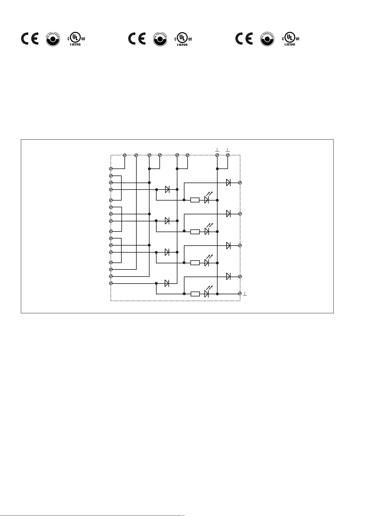
Zulassungen
Approvals
Homologations
Gerätebeschreibung
Gerätemerkmale:
• Anschlussmöglichkeit für max. 4 Sicherheitssensoren der Serie PSEN 2 oder
max. 4 Positionsschalter mit Öffner-/
Schließer-Kombination
• Statusanzeigen für den Schaltzustand der
Öffnerkreise der angeschlossenen
Sensoren
• 4 Diagnoseausgänge zur Anzeige oder
Auswertung des Schaltzustands der
Öffnerkreise über externe LEDs oder eine
Steuerung
11
12
13
14
21
22
23
24
31
32
33
34
41
42
43
44
Unit description
Unit features:
• Connection for max. 4 safety sensors from
the PSEN 2 series or max. 4 position
switches with N/C / N/O combination
• Status indicators for the switch status of
the N/C circuits of the connected sensors
• 4 diagnostic outputs to display or evaluate
the switch status of the N/C circuits via
external LEDs or a PLC
21
33 44
S1
S2
S3
S4
Description de l'appareil
Particularités :
• Possibilité de raccordement de max. 4
capteurs de sécurité PSEN 2 ou de max.
4 interrupteurs de position avec contacts
O/F
• Leds de visualisation des circuits d'ouverture des capteurs raccordés
• 4 sorties statiques d'information pour la
gestion par voyant externe ou API des
capteurs raccordés.
Y1
Y2
Y3
Y4
Innenschaltbild Internal wiring diagram Schéma interne
Funktionsbeschreibung
Das PSEN i1 schaltet die 4 Öffnerkreise der
angeschlossenen Sicherheitssensoren/
Positionsschalter parallel und die 4
Schließerkreise in Reihe. Eine Statusanzeige
leuchtet bei geschlossenem Schließerkreis.
Bei Verwendung
• von PNOZ e3.1p, PNOZ e3vp und
PNOZ e5.13p lassen sich durch Serienschaltung max. 16 Sicherheitssensoren/
Positionsschalter an 4 PSEN i1 anschließen.
• einer kompakten Sicherheitssteuerung der
Systemfamilie PSS, einer modularen
Sicherheitssteuerung der Systemfamilie
PSS mit zentraler Eingabebaugruppe oder
einer SafetyBUS p-fähigen PSS mit
dezentraler Eingabebaugruppe lassen sich
durch Serienschaltung max. 6 Sicherheitssensoren/Positionsschalter an 2 PSEN i1
anschließen.
• von PNOZmulti lassen sich durch Serienschaltung max. 6 Sicherheitsschalter/
Function description
The PSEN i1 switches the 4 N/C circuits of
the connected safety sensors/position
switches in parallel and the 4 N/O circuits in
series. A status indicator lights when the
N/O circuit is closed.
When using
• PNOZ e3.1p, PNOZ e3vp and
PNOZ e5.13vp a max. 16 safety sensors/
position switches can be connected to 4
PSEN i1 by linking in series.
• a compact programmable safety system
from the PSS-range, a modular
programmable safety system of the
PSS-range with centralised input module
or a SafetyBUS p-compatible PSS with
decentralised input module, a max. 6
safety sensors/position switches can be
connected to 2 PSEN i1 by linking in
series.
• PNOZmulti a max. 6 safety sensors/
position switches can be connected to 2
PSEN i1 by linking in series.
Description du fonctionnement
Le PSEN i1 met en parallèle les 4 contacts à
ouverture des capteurs de sécurité/
interrupteurs de position raccordés et en
série leur contact à fermeture. Une led de
visualisation permet de signaler l'état de
chaque capteur.
En cas d'utilisation
• avec PNOZ e3.1p, PNOZ e3vp et
PNOZ e5.13vp, la mise en série de max.
16 capteurs de sécurité/interrupteurs de
position via 4 PSEN i1 est possible.
• avec un automate de sécurité de la
gamme PSS, un automate modulaire de la
gamme PSS avec cartes centralisées ou
modules déportés via SafetyBUS p, la
mise en série de max. 6 capteurs de
sécurité/interrupteurs de position via 2
PSEN i1 est possible.
• avec un PNOZmulti, la mise en série de
max. 6 capteurs de sécurité/interrupteurs
de position via 2 PSEN i1 est possible.
Positionsschalter an 2 PSEN i1
anschließen.
- 2 -
Page 3
Schnittstelle montieren
Achtung! Montieren Sie das Gerät in
einen Schaltschrank mit einer
Schutzart von mindestens IP54.
• Befestigen Sie das Gerät mit Hilfe des
Rastelements auf der Rückseite auf einer
Normschiene.
• Sichern Sie das Gerät auf einer senkrechten Tragschiene (35 mm) durch ein
Halteelement (z. B. Endhalter oder
Endwinkel)
Gerät in Betrieb nehmen
Betriebsbereitschaft herstellen
PNOZ e3.1p oder PNOZ e3vp und
PNOZ e5.13p:
• Verbinden Sie das PSEN i1 mit einem der
genannten Schutztürwächter.
• Legen Sie bei dem Schutztürwächter die
Betriebsart (z. B. mit/ohne Querschlusserkennung) durch Verdrahten des Ein-
gangskreises fest.
Installing the interface
Caution!The unit should be installed
in a control cabinet with a protection
type of at least IP54.
• Use the notch on the back of the unit to
attach it to a DIN rail.
• Secure the unit on a vertical DIN rail (35
mm) using a retaining bracket or end angle
Commissioning the unit
Preparing for operation
PNOZ e3.1p or PNOZ e3vp and
PNOZ e5.13p:
• Connect the PSEN i1 to one of the named
safety gate monitors.
• Establish the operating mode on the safety
gate monitor (e.g. with/without detection of
shorts across contacts) through the wiring
of the input circuit.
Montage de l'interface
Attention ! Installez l'appareil dans
une armoire électrique ayant un
indice de protection minimum IP 54.
• Montez l'appareil sur un rail DIN à l'aide du
système de fixation situé au dos du relais.
• Fixez l'appareil sur un rail DIN vertical (35
mm) avec un élément de maintien comme
par ex. un support ou une équerre
terminale.
Mise en oeuvre
Mise en service en liaison avec
PNOZ e3.1p ou PNOZ e3vp et
PNOZ e5.13p :
• Reliez le PSEN i1 avec un des relais
électroniques ci-dessus.
• Définissez par câblage du circuit d'entrée
du relais de contrôle le mode de fonctionnement souhaité (par ex. avec ou sans
détection de courts-circuits).
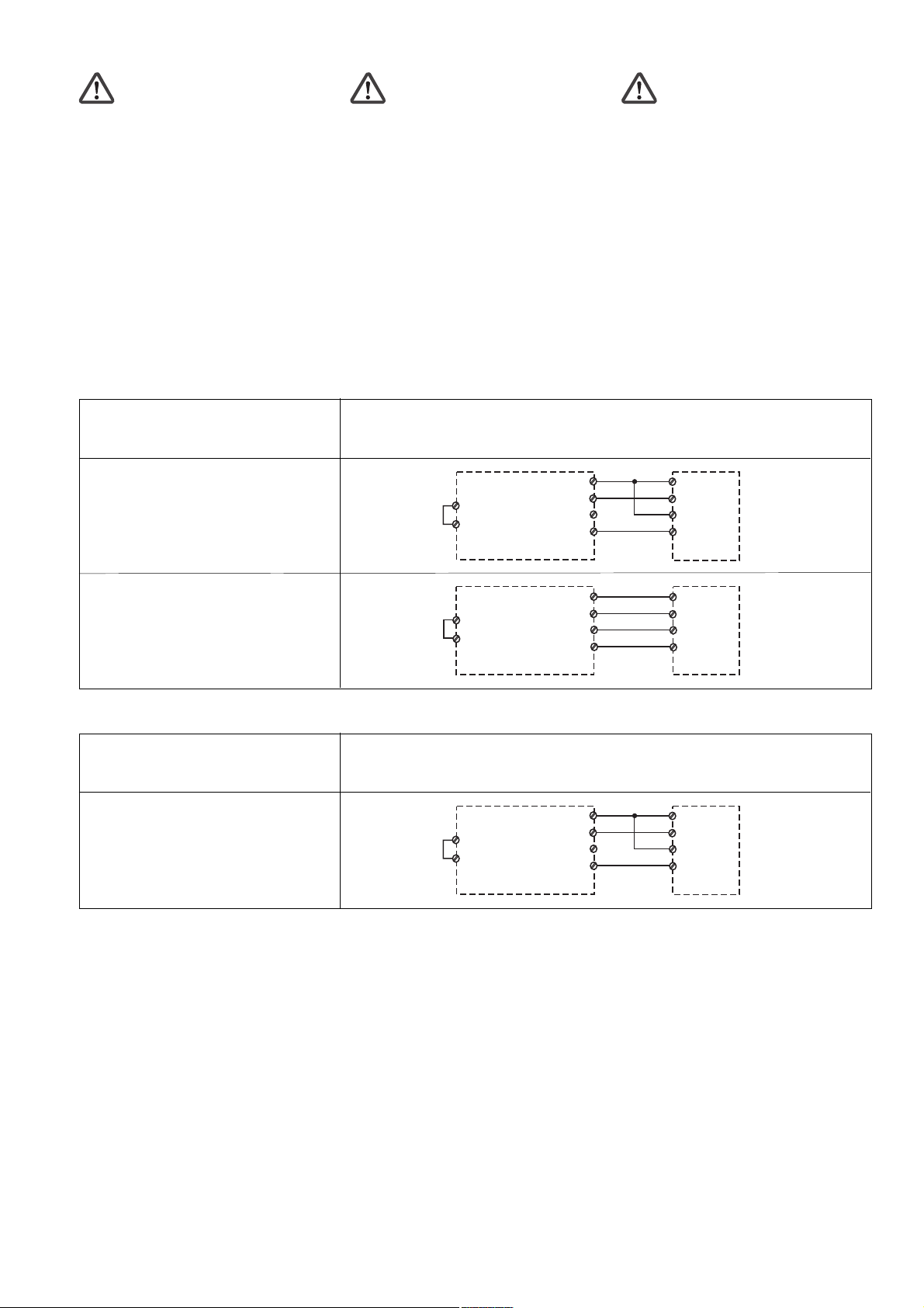
Eingangskreis PNOZ e3.1/PNOZ e3vp
Input circuit PNOZ e3.1/PNOZ e3vp
Circuit d’entrée PNOZ e3.1/PNOZ e3vp
ohne Querschlusserkennung
without detection of shorts across contacts
sans détection des courts-circuits
mit Querschlusserkennung
with detection of shorts across contacts
avec détection des courts-circuits
Eingangskreis PNOZ e5.13p
Input circuit PNOZ e5.13p
Circuit d’entrée PNOZ e5.13p
ohne Querschlusserkennung
without detection of shorts across contacts
sans détection des courts-circuits
Zweikanalig
Dual-channel
Commande par 2 canaux
Y4
S11
PNOZ e3.1p
PNOZ e3vp
Y4
S23
PNOZ e3.1p
PNOZ e3vp
Zweikanalig
Dual-channel
Commande par 2 canaux
Y37
Y36
S12
S24
S11
S12
S23
S24
S32
S44
A1
A1
1
2
3
4
PSEN i1
1
2
3
4
PSEN i1
1
2
3
4
PSEN i1PNOZ e5.13p
Betriebsbereitschaft herstellen
Sicherheitssteuerung der Systemfamilie
PSS und PNOZmulti:
• Verbinden Sie das PSEN i1 mit
- den Eingängen (kompakte PSS oder
PNOZmulti)
- den Eingängen der zentralen Eingabebaugruppe (modulare PSS)
- den Eingängen der dezentralen
Eingabebaugruppe (SafetyBUS p)
• Verwenden Sie die Taktausgänge zur
Querschlusserkennung.
Preparing for operation
Programmable safety system from the
PSS-range and PNOZmulti:
• Connect the PSEN i1 to
- the inputs (compact PSS or PNOZmulti)
- the inputs on the centralised input
module (modular PSS)
- the inputs on the decentralised input
module (SafetyBUS p)
• Use the test pulse outputs to detect shorts
across the contacts.
- 3 -
Mise en service en liaison avec
automates de sécurité PSS et PNOZmulti :
• Reliez le PSEN i1 avec
- les entrées de l'automate (PSS compact
ou PNOZmulti)
- les entrées de la carte centrale de
l'automate (PSS modulaire)
- les entrées du module décentralisé
(SafetyBUS p)
• Utilisez les sorties impulsionnelles pour la
détection des courts-circuits.
Page 4

Eingangskreis PSS/zentrale Eingabebaugruppe/dezentrale Eingabebaugruppe
Input circuit PSS/centralisend input module/
decentralised input module
Circuit d’entrée PSS/module d’entrée
centralisé/module d’entrée décentralisé
Zweikanalig
Dual-channel
Commande par 2 canaux
ohne Querschlusserkennung
without detection of shorts across contacts
sans détection des courts-circuits
mit Querschlusserkennung
with detection of shorts across contacts
avec détection des courts-circuits
Eingang/
Input/
Entrée
Eingang/
Input/
Entrée
Taktausgang 1/
Test pulse output 1/
Sortie impulsionnelle 1
Eingang/
Input/
Entrée
Taktausgang 2/
Test pulse output 2/
Sortie impulsionnelle 2
Eingang/
Input/
Entrée
+24 V DC
I 00
I 01
I 02
O 16
I 00
O 17
I 01
1
2
3
4
1
2
3
4
PSEN i1
PSEN i1
Anschluss an PNOZmulti Connection to PNOZmulti Raccordement au PNOZmulti
PNOZ m1p
T0
T1
I1
braun/brown/marron
I0
PSEN i1
11
weiß/white/blanc
12
blau/blue/
13
schwarz/black/noir
14
bleu
1
2
3
4
Sicherheitssensoren/Positionsschalter
anschließen:
• Verbinden Sie die Sicherheitssensoren/
Positionsschalter mit dem PSEN i1.
Wichtig: Beachten Sie beim
Anschluss von weniger als 4 Sicherheitssensoren/Positionsschaltern: freie
Schließerkontakte am PSEN i1
überbrücken.
Connecting the safety sensors/position
switches:
• Connect the safety sensors/position
switches to the PSEN i1.
Notice: When connecting less than 4
safety sensors/position switches,
please note: link out the free N/O
contacts on the PSEN i1.
1
marron
marron
marron
marron
2
+3
4
1
2
+3
4
1
2
+3
4
1
2
+3
4
PSEN i1
braun/brown/
11
weiß/white/blanc
12
blau/blue/bleu
13
schwarz/black/noir
14
braun/brown/
21
weiß/white/blanc
22
blau/blue/bleu
23
schwarz/black/noir
24
braun/brown/
31
weiß/white/blanc
32
blau/blue/bleu
33
schwarz/black/noir
34
braun/brown/
41
weiß/white/blanc
42
blau/blue/bleu
43
schwarz/black/noir
44
Raccordement des capteurs de sécurité/
interrupteurs de position :
• Câblez les capteurs de sécurité/interrupteurs de position sur le PSEN i1.
Important : en cas de raccordement
de moins de 4 capteurs de sécurité/
interrupteurs de position : ponter les
contacts à fermeture libres sur le
PSENi1.
Sicherheitssensoren/Positionsschalter
safety switches/position switches
capteurs de sécurité/interrupteurs de position
Sicherheitssensoren/Positionsschalter
anschließen
Connecting the safety sensors/position
switches
- 4 -
Raccorder des capteurs de sécurité/
interrupteurs de position
Page 5

Diagnoseausgänge beschalten:
• Beschalten Sie bei Bedarf die Diagnoseausgänge Y1 ... Y4 des PSEN i1.
Connecting the diagnostic outputs:
• If required, connect the diagnostic outputs
Y1 ... Y4 on the PSEN i1.
Raccordement des sorties diagnostic :
• Câblez si nécessaire les sorties Y1 ... Y4
du PSEN i1.
INFO: Beachten Sie beim Anschluss
der Diagnoseausgänge an eine
Steuerung: Betriebsart ohne
Querschlusserkennung verdrahten.
INFORMATION: When connecting the
diagnostic outputs to a PLC, please
note: use the operating mode without
detection of shorts across contacts.
Y1
Y2
Y3
Y4
PSEN i1
INFO: Utilisez le mode de fonctionnement sans détection de court-circuit
en cas de raccordement des sorties
diagnostic sur un automate .
Diagnoseausgänge anschließen Connecting the diagnostic outputs Raccorder les sorties diagnostic
Technische Daten
Versorgungsspannung U
Spannungstoleranz
Leistungsaufnahme bei U
ohne Last
Restwelligkeit U
B
Spannung und Strom an
Y1, Y2, Y3, Y4
Luft- und Kriechstrecken
Klimabeanspruchung
EMV
Schwingungen nach
Frequenz
Amplitude
Umgebungstemperatur
Lagertemperatur
Schutzart
Einbauraum (z. B. Schaltschrank)
Gehäuse
Klemmenbereich
Anschlussart
B
B
Technical details
Supply voltage U
Voltage tolerance
Power consumption at U
without load
Residual ripple U
Voltage and Current at
Y1, Y2, Y3, Y4
Airgap creepage
Climatic suitability
EMC
Vibration to
Frequency
Amplitude
Ambient temperature
Storage temperature
Protection type
Mounting (e.g. control cabinet)
Housing
Terminals
Connection type
B
B
B
Caractéristiques techniques
Tension d’alimentation U
Page de la tension d'alimentation
Consommation pour U
sans charge
Ondulation résiduelle U
Tension, courant aux bornes
Y1, Y2, Y3, Y4
Cheminement et claquage
Sollicitations climatiques
CEM
Oscillations selon
fréquence
amplitude
Température d'utilisation
Température de stockage
Indice de protection
Lieu d’implantation (ex. armoire)
Boîtier
Borniers
Mode de raccordement
B
B
B
von/from/de PNOZ
oder/or/ou PSS
80...125%
max. 0,4 W
DC: 20%
24V/50 mA
DIN VDE 0110-1, 04/97
DIN IEC 60068-2-3, 12/86
EN 60947-5-3, 05/99
EN 60068-2-6, 04/95
10...55 Hz
0,35 mm
-10...+55 °C
-25...+70 °C
IP54
IP20
IP20
Federkraftklemmen/
spring-loaded terminals/
borniers à ressorts
Querschnitt des Außenleiters
1 Leiter
flexibel
2 Leiter gleichen Querschnitts
flexibel mit Aderendhülse ohne
Kunststoffhülse
flexibel ohne Aderendhülse oder
mit TWIN-Aderendhülse
Gehäusematerial
Gehäuse
Fuß
Abmessungen H x B x T
Cable cross section
1 core
flexible
2 core, same cross section
flexible with crimp connectors,
without insulating sleeve
flexible without crimp connectors or
with TWIN crimp connectors
Housing material
Housing
Base
Dimensions H x W x D
Capacité de raccordement
1 conducteur
souple
2 câbles de même diamètre
souple avec embout sans
chapeau plastique
souple sans embout ou avec
embout TWIN
Matériau du boîtier
boîtier
socle
Dimensions H x L x P
0,08 ... 2,5 mm
0,08 ... 1 mm
0,08 ... 1,5 mm
PA 6 UL 94-HB
PA 66 UL 94-V2
96 x 48 x 43,5 mm
(3.77" x 1.88" X 1.71")
Gewicht
Weight
Poids
90 g
2
2
2
- 5 -
Page 6

DD
D
DD
Anschlussbeispiel:
Auswertung (PNOZ e3.1p) von 2 Sicherheitssensoren PSEN 2.1p-10
L+
GBGB
GB
GBGB
Connection example:
Evaluation (PNOZ e3.1p) of 2 safety sensors
PSEN 2.1p-10
K10
K9
FF
F
FF
Exemple de raccordement :
Unité de contrôle (PNOZ e3.1p) avec 2
capteurs de sécurité PSEN 2.1p-10
L-
DD
D
DD
Anschlussbeispiel:
Auswertung (PNOZ e3.1p) von 6 Sicherheitssensoren über 3 in Reihe geschaltete
PSEN i1.
S12Y6S24
A1
PNOZ e3.1p
A2
14
K10
K9
1 233 4 4
S34Y4
S11
PSEN i1
Y1 Y2 Y3 Y4
Y32S35
S36
S23
GBGB
GB
GBGB
Y524
11 12 13 14 21 22 23 24
31 32 33 34 41 42 43 44
1234
PSEN 2.1p-10
1234
PSEN 2.1p-10
Connection example:
Evaluation (PNOZ e3.1p) of 6 safety sensors
via 3 PSEN i1 units connected in series.
FF
F
FF
Exemple de raccordement :
Unité de contrôle (PNOZ e3.1p) avec 6
capteurs de sécurité PSEN 2.1p-10 câblés à
l’aide de 3 PSEN i1 en série
L+
K10
K9
S12Y6S24
A1
PNOZ e3.1p
A2
14
K10
K9
L-
S11
S36
S23
S34Y4
Y32S35
Y524
1 233 4 4
PSEN i1
Y1 Y2 Y3 Y4
11 12 13 14 21 22 23 24
31 32 33 34 41 42 43 44
1234
PSEN 2.1p-10
1234
PSEN 2.1p-10
1 233 4 4
PSEN i1
Y1 Y2 Y3 Y4
11 12 13 14 21 22 23 24
31 32 33 34 41 42 43 44
1234
PSEN 2.1p-10
1234
PSEN 2.1p-10
1 233 4 4
PSEN i1
Y1 Y2 Y3 Y4
11 12 13 14 21 22 23 24
31 32 33 34 41 42 43 44
1234
PSEN 2.1p-10
1234
PSEN 2.1p-10
- 6 -
Page 7

DD
D
DD
Abmessungen in mm (") Dimensions en mm (")
GBGB
GB
GBGB
Dimensions in mm (")
FF
F
FF
48 (1.88")
43,5 (1.71")
PSEN i1
96 (3.77")
DD
D
DD
Anschlussbelegung Affectation des raccords
GBGB
GB
GBGB
Connector pin assignment
FF
F
FF
123344
S1
S2 S3 S4
PSEN i1
Y1 Y2 Y3 Y4
11 12 13 14 21 22 23 24
31 32 33 34 41 42 43 44
- 7 -
Page 8

A
Pilz Ges.m.b.H., ✆ 01 7986263-0, Fax: 01 7986264, E-Mail: pilz@pilz.at
safety@pilz.com.au
E-Mail: pilz@pilzbr.com.br
✆
74436332, Fax: 74436342, E-Mail: pilz@pilz.dk
Electronic,
pilz.fi@pilz.dk
Fax: 031 789555, E-Mail: info@pilz.it
Ltd.,
✆
045 471-2281, Fax: 045 471-2283, E-Mail: pilz@pilz.co.jp
info@mx.pilz.com
352, E-Mail: t.catterson@pilz.co.nz
Office,
✆
021 62494658, Fax: 021 62491300,
SE
Pilz Skandinavien K/S, ✆ 0300 13990, Fax: 0300 30740, E-Mail: pilz.se@pilz.dk
✆
0224 2360180, Fax: 0224 2360184, E-Mail: pilz.tr@pilz.de
info@pilzusa.com
www
www.pilz.com
D
Pilz GmbH & Co. KG, Sichere Automation, Felix-Wankel-Straße 2, 73760 Ostfildern, Deutschland, ✆ +49 711 3409-0, Fax: +49 711 3409-133,
E-Mail: pilz.gmbh@pilz.de
B L
✆
03 88104000, Fax: 03 88108000, E-Mail: siege@pilz-france.fr
GB
Pilz Belgium, ✆ 09 3217570, Fax: 09 3217571, E-Mail: info@pilz.be
CH
Pilz lndustrieelektronik GmbH, ✆ 062 88979-30, Fax: 062 88979-40, E-Mail: pilz@pilz.ch
Pilz Automation Technology, ✆ 01536 460766, Fax: 01536 460866, E-Mail: sales@pilz.co.uk
IRL
E
Pilz lndustrieelektronik S.L., ✆ 938497433, Fax: 938497544, E-Mail: pilz@pilz.es
Pilz Ireland Industrial Automation, ✆ 021 4346535, Fax: 021 4804994, E-Mail: sales@pilz.ie
MEX
NL
Pilz Nederland, ✆ 0347 320477, Fax: 0347 320485, E-Mail: info@pilz.nl
P
Pilz Industrieelektronik S.L., ✆ 229407594, Fax: 229407595, E-Mail: pilz@pilz.es
E-Mail: sales@pilz.com.cn
USA
AUS
Pilz Australia, ✆ 03 95446300, Fax: 03 95446311, E-Mail:
BR
Pilz do Brasil, ✆ 11 4337-1241, Fax: 11 4337-1242,
DK
FIN
Pilz Skandinavien K/S, ✆ 09 27093700, Fax: 09 27093709, E-Mail:
Pilz de Mexico, S. de R.L. de C.V., ✆ 55 5572 1300, Fax: 55 5572 4194, E-Mail:
NZ
ROK
Pilz Automation Safety L.P., ✆ 734 354-0272, Fax: 734 354-3355, E-Mail:
Pilz Korea, ✆ 031 8159541, Fax: 031 8159542, E-Mail: info@pilzkorea.co.kr
TR
Pilz Elektronik Güvenlik Ürünleri ve Hizmetleri Tic. Ltd. ¸Sti.,
I
Pilz ltalia Srl, ✆ 031 789511,
Pilz New Zealand, ✆ 09- 6345-350, Fax: 09-6345-
PRC
Pilz China Representative
- 8 -
Pilz Skandinavien K/S,
F
Pilz France
J
Pilz Japan Co.,
20 776-05-2009-04 Printed in Germany
 Loading...