

Page 1

Operating Manual PSSu H m F DP ETH SD
Operating Manual PSSu H m F DP ETH SD
PSEN enc m1 eCAM, PSEN enc m2 eCAM
PSEN enc s1 eCAM, PSEN enc s2 eCAM
Position Monitoring
Operating Manual — No. 1002327-EN-04
Page 2

This document is a translation of the original document.
All rights to this documentation are reserved by Pilz GmbH & Co. KG. Copies may be made
for internal purposes.
Suggestions and comments for improving this documentation will be gratefully received.
Pilz®, PIT®, PMI®, PNOZ®, Primo®, PSEN®, PSS®, PVIS®, SafetyBUS p®, SafetyEYE®,
SafetyNET p®, the spirit of safety® are registered and protected trademarks of
Pilz GmbH & Co. KG in some countries.
SD means Secure Digital.
Preface
Page 3

Contents
Contents
Contents .................................................................................................................. 1
1 General ................................................................................................................. 3
1.1 Scope ...................................................................................................................................... 3
1.2 Applied directives and standards ............................................................................................ 4
1.3 General function description ................................................................................................... 5
1.3.1 Main features .......................................................................................................... 5
1.3.2 Overall system overview ......................................................................................... 6
2 Essential safety information ............................................................................... 7
2.1 Definition of symbols and instructions .................................................................................... 7
2.2 General hazards when using the product ............................................................................... 8
2.3 Intended use ........................................................................................................................... 9
2.4 Warranty and liability .............................................................................................................. 10
2.5 Organisational measures ........................................................................................................ 11
2.6 Selection and qualification of personnel; fundamental obligations ......................................... 11
2.7 Safety information ................................................................................................................... 12
3 Transport / storage .............................................................................................. 14
4 Assembly .............................................................................................................. 15
4.1 Solid shaft version PSEN enc m2 eCAM ................................................................................ 15
4.1.1 Requirements .......................................................................................................... 15
4.2 Hollow shaft version PSEN enc m1 eCAM ............................................................................. 17
4.2.1 Requirements .......................................................................................................... 17
4.2.2 Dowel pin ................................................................................................................ 19
English
5 Installation / Preparation for commissioning .................................................... 21
5.1 EMC requirements .................................................................................................................. 21
5.2 SSI communication mode ....................................................................................................... 23
5.3 SSI, RS422 communication technology ................................................................................. 24
5.4 Cable specification .................................................................................................................. 26
5.5 Connection .............................................................................................................................. 27
5.5.1 Supply voltage, X1 .................................................................................................. 28
5.5.2 Measuring systems, X2 .......................................................................................... 29
5.6 Shield connection ................................................................................................................... 30
5.7 Count direction ........................................................................................................................ 34
5.8 SSI interface ........................................................................................................................... 35
5.9 Incremental interface .............................................................................................................. 37
Pilz GmbH & Co. KG, Felix-Wankel-Straße 2, 73760 Ostfildern, Deutschland
Telefon +49 711 3409-0, Telefax +49 711 3409-133, E-Mail: pilz.gmbh@pilz.de
1
Page 4

Contents
5.10 LED status display ................................................................................................................ 39
6 SSI format ............................................................................................................. 40
6.1 Sign of life counter .................................................................................................................. 40
English
7 Replacing the measuring system ....................................................................... 41
8 Technical details ................................................................................................. 43
5.9.1 Signal characteristic of the incremental interface ................................................... 37
Pilz GmbH & Co. KG, Felix-Wankel-Straße 2, 73760 Ostfildern, Deutschland
Telefon +49 711 3409-0, Telefax +49 711 3409-133, E-Mail: pilz.gmbh@pilz.de
2
Page 5

General
1 General
1.1 Scope
This operating manual includes the following topics:
● General function description
● Essential safety information with details of intended use
● Characteristic data
● Assembly
● Installation/commissioning
● SSI interface
This operating manual applies exclusively to the following measuring systems with
SSI interface:
● PSEN enc m1 eCAM
● PSEN enc m2 eCAM
● PSEN enc s1 eCAM
● PSEN enc s2 eCAM
The products are labelled via nameplates and form part of a system.
English
Pilz GmbH & Co. KG, Felix-Wankel-Straße 2, 73760 Ostfildern, Deutschland
Telefon +49 711 3409-0, Telefax +49 711 3409-133, E-Mail: pilz.gmbh@pilz.de
3
Page 6

General
1.2 Applied directives and standards
The measuring systems PSEN enc m1 eCAM and PSEN enc m2 eCAM have been developed,
designed and manufactured in compliance with the applicable European and international standards,
English
directives and regulations.
Directives
- 2004/108/EC (L 390/24) EMC Directive
EMC; Immunity in accordance with EN 61000-6-2:2005, industrial environment:
- DIN EN 61000-4-2:2009 Electrostatic discharge, ESD
- DIN EN 61000-4-3:2008 High frequency electromagnetic fields
- DIN EN 61000-4-4:2005 Fast transient electrical disturbances, burst
- DIN EN 61000-4-5:2007 Surge voltages
- DIN EN 61000-4-6:2009
EMC; Emissions in accordance with EN 61000-6-3:2007, residential environment:
- EN 55022:2006 Disturbance field strength, 30 MHz - 1 GHz
- EN 55022:2006 Interference voltage, < 30 MHz
- DIN EN 61326-3-2:2008
Environmental influences
- DIN EN 60068-2-6:2008 Sinusoidal vibration
- DIN EN 60068-2-64:2009 Broadband noise (digitally controlled)
- DIN EN 60068-2-29:1995 Shock and continuous shock tests
- DIN EN 60529:2000 Degrees of protection, IP code
Other requirements
- VDE 0100 Erection of low voltage installations
Conducted disturbances,
induced by high frequency fields
Immunity requirements for safety-related systems and
for equipment
Pilz GmbH & Co. KG, Felix-Wankel-Straße 2, 73760 Ostfildern, Deutschland
Telefon +49 711 3409-0, Telefax +49 711 3409-133, E-Mail: pilz.gmbh@pilz.de
4
Page 7

General
1.3 General function description
The rotary measuring system
• PSEN enc mx eCAM is an absolute multi-turn position measuring system with
synchronous serial interface (SSI).
• PSEN enc sx eCAM is an absolute single-turn position measuring system with
synchronous serial interface (SSI).
The measuring system consists of a redundant, dual-channel system, in which
optical and magnetic sensing units are arranged on a drive shaft, designed as a
hollow shaft or solid shaft.
1.3.1 Main features
● SSI interface, to output data from measuring channel 1
● SSI interface, to output data from measuring channel 2
● Measuring channel 1:
- Single-turn: optical single-turn sensing via code disk (transmitted light)
- Multi-turn: optical single-turn sensing via code disk (transmitted light) and
magnetic multi-turn sensing
● Measuring channel 2:
- Single-turn: magnetic single-turn sensing
- Multi-turn: magnetic single and multi-turn sensing
● Additional incremental interface
● Mechanically, the two systems are connected only by the common drive shaft and
the housing
● Measuring channels have a common voltage terminal, but are electrically isolated
internally via two separate power supplies
● A common drive shaft
● 2 Installation Types:
- Hollow shaft version: PSEN enc m1 eCAM and PSEN enc s1 eCAM
- Solid shaft version: PSEN enc m2 eCAM and PSEN enc s2 eCAM
The optical system has greater accuracy due to the technology.
The magnetic sensing system is a fully-fledged second measuring channel and
operates independently from the first measuring channel. The two measuring systems
have their own SSI interfaces, which transmit the same data format.
The data from measuring channel 1 is also output via an incremental interface.
English
Pilz GmbH & Co. KG, Felix-Wankel-Straße 2, 73760 Ostfildern, Deutschland
Telefon +49 711 3409-0, Telefax +49 711 3409-133, E-Mail: pilz.gmbh@pilz.de
5
Page 8
General
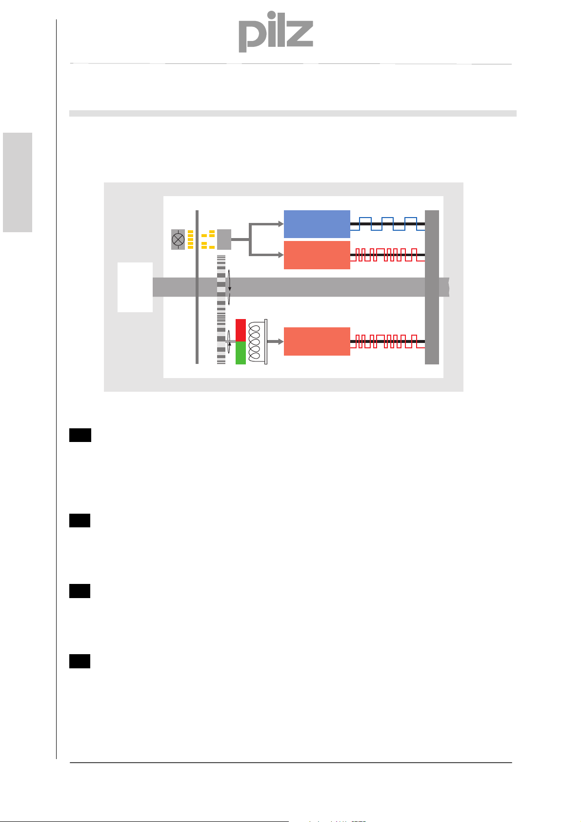
1.3.2 Overall system overview
English
A
Measuring channel 1, single-turn and multi-turn
● Optical detection of the number of steps/revolution
● Max. 8192 steps/revolution, accuracy: 13 Bit
● Synchronous serial interface (SSI)
● Incremental signals for position feedback
B
Measuring channel 1, multi-turn
● Magnetic detection of the number of revolutions
● Max. 4096 revolutions
● Synchronous serial interface (SSI)
C
Measuring channel 2, single-turn and multi-turn
● Magnetic detection of the number of steps/revolution
● Max. 8192 steps/revolution, accuracy: 8 Bit
● Synchronous serial interface (SSI)
D
Measuring channel 2, multi-turn
● Magnetic detection of the number of revolutions
● Max. 4096 revolutions
● Synchronous serial interface (SSI)
optische Abtastung
Antrieb
Fig. 1: System schematic
Inkremental-
Interface
SSI
Welle
Anschlussklemme
N
SSI
S
magnetische Abtastung
Pilz GmbH & Co. KG, Felix-Wankel-Straße 2, 73760 Ostfildern, Deutschland
Telefon +49 711 3409-0, Telefax +49 711 3409-133, E-Mail: pilz.gmbh@pilz.de
6
Page 9
Essential safety information
2 Essential safety information
2.1 Definition of symbols and instructions
DANGER!
This means that death or serious injury will occur if the
relevant preventive measures are not taken.
WARNING!
This means that death or serious injury can occur if the
relevant preventive measures are not taken.
English
CAUTION!
This means that a minor injury can occur if the relevant
preventive measures are not taken.
NOTICE
This means that material damage can occur if the relevant
preventive measures are not taken.
INFORMATION
This indicates important information or features and
application tips for the relevant product.
This means that the relevant ESD protective measures must
be considered in accordance with DIN EN 100 015-1.
(Equipotential bonding between the body and the unit or
housing earth via a high impedance resistor (approx. 1
MOhm) e.g. using a standard ESD arm band).
Pilz GmbH & Co. KG, Felix-Wankel-Straße 2, 73760 Ostfildern, Deutschland
Telefon +49 711 3409-0, Telefax +49 711 3409-133, E-Mail: pilz.gmbh@pilz.de
7
Page 10

Essential safety information
2.2 General hazards when using the product
English
The product, described below as the measuring system, is manufactured using
state-of-the-art technology. Nevertheless, use of the system outside its intended
purpose may pose a risk to the life and limb of the user or third-party or
adversely affect the measuring system and other material assets!
The measuring system should only be used when in perfect working order, in
accordance with its intended use, in awareness of safety measures and hazards and
in compliance with the operating manual! In particular, errors that could adversely
affect safety must be rectified without delay!
Pilz GmbH & Co. KG, Felix-Wankel-Straße 2, 73760 Ostfildern, Deutschland
Telefon +49 711 3409-0, Telefax +49 711 3409-133, E-Mail: pilz.gmbh@pilz.de
8
Page 11

Essential safety information
2.3 Intended use
The measuring system can be used to detect angular movement and to prepare
measured data for control systems within plants.
Intended use includes:
● Compliance with all the instructions in this operating manual
● Compliance with the information on the nameplate and any prohibition or
instruction labels on the measuring system
● Compliance with the operating manual provided by the machine or plant
manufacturer
● Operation of the measuring system within the limit values stated in the technical
details
● Assurance that the failsafe processing unit (control system) fulfils all the required
safety functions
● Compliance with and use of the check list in the Appendix
● Assurance that the measuring system is mounted safely on the driving axis
In particular, the system shall not be used:
English
● In environments with an explosive atmosphere
● For medical purposes
Pilz GmbH & Co. KG, Felix-Wankel-Straße 2, 73760 Ostfildern, Deutschland
Telefon +49 711 3409-0, Telefax +49 711 3409-133, E-Mail: pilz.gmbh@pilz.de
9
Page 12

Essential safety information
2.4 Warranty and liability
English
All claims to warranty and liability will be rendered invalid if
● The product was used contrary to the purpose for which it is intended
● Damage can be attributed to not having followed the guidelines in the manual
● Operating personnel are not suitably qualified
● Any type of modification has been made (e.g. exchanging components on the
PCB boards, soldering work etc.).
Pilz GmbH & Co. KG, Felix-Wankel-Straße 2, 73760 Ostfildern, Deutschland
10
Telefon +49 711 3409-0, Telefax +49 711 3409-133, E-Mail: pilz.gmbh@pilz.de
Page 13

Essential safety information
2.5 Organisational measures
● The operating manual must always be kept ready-to-hand at the location where
the measuring system is used
● In addition to the operating manual there are also generally applicable legal and
other binding regulations regarding accident prevention and environmental
protection, which must be observed and communicated.
● The respective national, local and plant-specific provisions and requirements must
be observed and communicated
● It is the responsibility of the operator to advise staff of any special operational
features and requirements
● Before starting work, any staff charged with operating the measuring system must
have read and understood the operating manual, in particular the chapter entitled
“Essential safety information”.
● The nameplate and any prohibition or instruction labels on the measuring system
must always be maintained in a legible condition.
● No mechanical or electrical modifications may be made to the measuring system
except for those expressly described in the operating manual.
● Repairs may only be made by the manufacturer, or by a body or person
authorised by the manufacturer.
English
2.6 Selection and qualification of personnel; fundamental obligations
● All work on the measuring system must only be carried out by qualified technical
personnel.
Qualified personnel are those who have been authorised by those responsible for
plant safety to carry out the necessary work, based on their training, experience
and instruction, as well as their knowledge of the relevant standards, provisions,
accident prevention regulations and operating conditions. They are able to identify
and avoid potential hazards.
● For a definition of "Qualified personnel" you can also refer to the standards VDE
0105-100 and IEC 364 (sources: Beuth Verlag GmbH, VDE Verlag GmbH, for
example).
● Responsibility for assembly, installation, commissioning and operation must be
clearly defined. There is an obligation to supervise trainees or apprentices.
Pilz GmbH & Co. KG, Felix-Wankel-Straße 2, 73760 Ostfildern, Deutschland
Telefon +49 711 3409-0, Telefax +49 711 3409-133, E-Mail: pilz.gmbh@pilz.de
11
Page 14

Essential safety information
2.7 Safety information
English
Please note:
– Wiring work should only be carried out when the supply voltage is
switched off; the same applies when opening and closing electrical
connections.
– Do not undertake any welding operations if the measuring system is
already wired / switched on.
– An appropriate heating/cooling measure should be used at the
installation site to prevent the ambient temperature exceeding or falling
below the permitted limit values.
– The measuring system must be installed so that direct moisture cannot
affect the measuring system.
– Appropriate ventilation/venting or heating/cooling measures at the
installation site must prevent values falling below the dew point
(condensation).
– If an overvoltage of >36 VDC is applied inadvertently, the measuring system
must be inspected on site and the reasons/circumstances stated.
– Checks must examine the potential hazards arising from interaction
with other systems and devices which are or will be installed in the
vicinity. It is the user’s responsibility to take appropriate measures.
– The supply voltage must be protected with a fuse appropriate for the
cable cross section.
– Cables must be suitable for the relevant temperature range.
– The measuring system should not be operated if it is defective.
– Ensure that the installation environment is protected from aggressive
media (acids etc.).
– Shocks to the shaft (e.g. hammer blows) should be avoided during
installation.
– The measuring system must not be opened.
– The nameplate specifies the technical properties of the measuring
system. If the nameplate is no longer legible or is missing altogether,
the measuring system must no longer be put into service.
Pilz GmbH & Co. KG, Felix-Wankel-Straße 2, 73760 Ostfildern, Deutschland
12
Telefon +49 711 3409-0, Telefax +49 711 3409-133, E-Mail: pilz.gmbh@pilz.de
Page 15

Essential safety information
The measuring system contains electrostatically sensitive
assemblies and components, which can be damaged if handled
incorrectly.
Avoid finger contact with the measuring system connection contacts and
apply the relevant ESD protective measures.
Disposal
If the device is to be disposed of after its service life, the applicable
country-specific regulations must be observed.
English
Pilz GmbH & Co. KG, Felix-Wankel-Straße 2, 73760 Ostfildern, Deutschland
Telefon +49 711 3409-0, Telefax +49 711 3409-133, E-Mail: pilz.gmbh@pilz.de
13
Page 16

Transport / storage
3 Transport / storage
English
● Transport instructions
– Do not drop the device or expose it to heavy impact!
The device contains an optical system.
– Only the original packaging should be used!
Inappropriate packaging material can result in the device becoming
damaged in transit.
● Storage
– Storage temperature: -30 to +80℃
– Store in a dry place
Pilz GmbH & Co. KG, Felix-Wankel-Straße 2, 73760 Ostfildern, Deutschland
14
Telefon +49 711 3409-0, Telefax +49 711 3409-133, E-Mail: pilz.gmbh@pilz.de
Page 17

Assembly
4 Assembly
4.1 Solid shaft version
The measuring system is connected to the drive shaft via an elastic coupling. The
coupling absorbs any deviations in the axial and radial direction between the
measuring system and drive shaft. This prevents excessive load on the bearing.
The centering collar with selective fit is used for centering in relation to the shaft. The
device is fixed to the machine using three screws in the flange.
All the fixing screws must be secured to stop them coming loose unintentionally.
4.1.1 Requirements
As the installation is application-dependent, the following instructions do not
claim to be exhaustive.
English
An appropriate coupling with positive-locking connection must be used in
the application.
The instructions and installation specifications provided by the coupling
manufacturer must be observed.
In particular you must ensure that
– the coupling is suitable for the specified speed and the potential axial
offset
– the device must be installed on a greaseless shaft
– the coupling and measuring system must not have an axial load
– the clamping screws must be tightened with the torque defined by the
coupling manufacturer
– the coupling screws must be secured to stop them coming loose
unintentionally.
The coupling fixing should prevent axial slippage of the measuring
system on the drive shaft, see Figure 2, 1 .
Positive locking using a parallel key/groove combination (Fig. 2, 2 )
should prevent radial slippage of the measuring system on the drive
shaft; a coupling with groove should be used for this purpose.
Pilz GmbH & Co. KG, Felix-Wankel-Straße 2, 73760 Ostfildern, Deutschland
Telefon +49 711 3409-0, Telefax +49 711 3409-133, E-Mail: pilz.gmbh@pilz.de
15
Page 18

Assembly
English
Fig. 2: Flange assembly
Pilz GmbH & Co. KG, Felix-Wankel-Straße 2, 73760 Ostfildern, Deutschland
16
Telefon +49 711 3409-0, Telefax +49 711 3409-133, E-Mail: pilz.gmbh@pilz.de
Page 19

Assembly
4.2 Hollow shaft version
4.2.1 Requirements
English
As the installation is application-dependent, the following instructions do not
claim to be exhaustive.
The measuring system should be installed on a greaseless shaft.
The clamping ring fixing should prevent axial slippage of the measuring
system on the drive shaft, see Figure 3.
Additional measures may be required to prevent axial slippage of the
measuring system.
The clamping of the measuring system must not have an axial load.
The screw on the clamping ring must be tightened to 3 Nm using a
torque wrench.
The screw on the clamping ring must be secured to stop it coming loose
unintentionally.
Positive locking using a parallel key/groove combination should prevent
radial slippage of the measuring system on the drive shaft; the
measuring system must be fixed to the drive side using a dowel pin, see
Fig. 4.
Fig. 3: Friction locking
Pilz GmbH & Co. KG, Felix-Wankel-Straße 2, 73760 Ostfildern, Deutschland
Telefon +49 711 3409-0, Telefax +49 711 3409-133, E-Mail: pilz.gmbh@pilz.de
17
Page 20

Assembly
English
Fig. 4: Positive locking
Fig. 5: Requirements of the shaft mounting
Pilz GmbH & Co. KG, Felix-Wankel-Straße 2, 73760 Ostfildern, Deutschland
18
Telefon +49 711 3409-0, Telefax +49 711 3409-133, E-Mail: pilz.gmbh@pilz.de
Page 21

Assembly
4.2.2 Dowel pin
Simultaneous rotation of the measuring system, caused by the resulting torque, is
prevented by a dowel pin on the machine side. The measuring system has a 6 mm
deep 4K7 groove insertion on the back to hold the dowel pin. The dowel pin must
reach at least 4 mm into the groove insertion.
English
Fig. 6: Using a dowel pin to prevent simultaneous rotation
When inserting the measuring system, position it so that the dowel pin is seated
correctly in the groove insertion. By tightening the clamping ring with the Allen key, the
measuring system is protected against slippage on the shaft.
Pilz GmbH & Co. KG, Felix-Wankel-Straße 2, 73760 Ostfildern, Deutschland
Telefon +49 711 3409-0, Telefax +49 711 3409-133, E-Mail: pilz.gmbh@pilz.de
19
Page 22

Assembly
English
Fig. 7: Assembly schematic
Pilz GmbH & Co. KG, Felix-Wankel-Straße 2, 73760 Ostfildern, Deutschland
20
Telefon +49 711 3409-0, Telefax +49 711 3409-133, E-Mail: pilz.gmbh@pilz.de
Page 23

Installation / Preparation for commissioning
5 Installation / Preparation for commissioning
5.1 EMC requirements
CAUTION!
Invalid measurement values due to radiated and
conducted interference!
• Radiated interference from hand-held radios, lightning
strikes on the network, mobile phones and emissions from
individual devices can cause the measuring system to
malfunction.
English
Pilz GmbH & Co. KG, Felix-Wankel-Straße 2, 73760 Ostfildern, Deutschland
Telefon +49 711 3409-0, Telefax +49 711 3409-133, E-Mail: pilz.gmbh@pilz.de
21
Page 24

Installation / Preparation for commissioning
English
• In particular, sources of conducted interference such as frequency-
controlled drives (circuit feedback) have a negative effect on the function of
the measuring system.
The 24 V power supplies must comply with SELV/PELV.
The shielding effect of cables must also be guaranteed after
installation (bending radius!) and after changing connectors. If in
doubt, use a more flexible cable with a higher current carrying
capacity.
For the drive/motor cabling, use a 5-core cable on which the PE
conductor is separate from the N-conductor (TN network). This will
largely prevent equipotential bonding currents and the development of
interference.
Shielded, stranded data cable must be used to make the system highly
resistant to electromagnetic interference. Where possible, the shield
should be connected to the protective earth at both ends and with
good conductivity using large screen clamps. Only if the machine earth
is subjected to heavy interference in comparison with the control
cabinet earth should the shield only be earthed at one end in the
control cabinet.
Equipotential bonding measures must be provided for the whole of the
plant’s processing chain.
Power and signal cables should be laid separately.
Comply with the manufacturer’s instructions when installing converters
and shielding the power cables between the frequency converter and
motor.
The energy supply should be adequately dimensioned.
The measuring system should be separated or segregated from
potential interfering transmitters.
Use of filters should be envisaged.
Internal and external protection against lightning should be considered.
The plant installer must adapt the cable routing to local conditions.
Compliance with the relevant standards and directives is essential to
Pilz GmbH & Co. KG, Felix-Wankel-Straße 2, 73760 Ostfildern, Deutschland
Telefon +49 711 3409-0, Telefax +49 711 3409-133, E-Mail: pilz.gmbh@pilz.de
22
guarantee safe, interference-free operation!
In particular, compliance with the applicable EMC Directive and shielding /
earthing guidelines should be guaranteed!
Page 25

Installation / Preparation for commissioning
5.2 SSI communication mode
SSI mode is a synchronous serial communication mode for the position of the
measuring system. By using the RS422 interface for communication, sufficiently high
transmission rates can be achieved.
The measuring system receives a sequence of clock signals from the data receiver
(control system) and responds with the current position value, which is transmitted
serially and synchronously with the sent clock pulse.
As data transfer is synchronised by the start of the clock signals, it is not necessary to
use single-step codes such as Gray code, for example.
The data signals Data+ and Data– are sent using cable transmitters (RS422). The
clock signals Clock+ and Clock- are received via optocouplers to protect against
damage resulting from interference, potential differences or reverse polarity.
+5V
Opto-Koppler
BAV99
65
English
Ω
SSI-Clock+
C
N.C.
GND
C
Fig. 8: SSI principle input circuit (Key: Opto-Koppler – Optocoupler)
Data+
RS422
Data-
Fig. 9: SSI output circuit
2.2 nF
65
Ω
SSI-Clock-
Pilz GmbH & Co. KG, Felix-Wankel-Straße 2, 73760 Ostfildern, Deutschland
Telefon +49 711 3409-0, Telefax +49 711 3409-133, E-Mail: pilz.gmbh@pilz.de
23
Page 26

Installation / Preparation for commissioning
5.3 SSI, RS422 communication technology
English
RS422 communication requires one cable pair for the signals Data+ and Data– and
one cable pair for the signals Clock+ and Clock–.
The serial data is transmitted without reference to earth as a voltage difference
between two corresponding cables.
The receiver simply evaluates the difference between two cables, so that commonmode interference on the transmission line does not corrupt the usable signal.
By using shielded stranded pair cable, data transmission can be realised over
distances of up to 500 metres at a frequency of 100 kHz.
Under load, RS422 transmitters provide output levels of ± 2 V between the two
outputs; the receivers still recognise levels of ± 200 mV as a valid signal.
Differential signal (A-B)
Idle signal = 3 V
Pilz GmbH & Co. KG, Felix-Wankel-Straße 2, 73760 Ostfildern, Deutschland
24
Telefon +49 711 3409-0, Telefax +49 711 3409-133, E-Mail: pilz.gmbh@pilz.de
Page 27

Installation / Preparation for commissioning
Idle signal = 2 V
English
Pilz GmbH & Co. KG, Felix-Wankel-Straße 2, 73760 Ostfildern, Deutschland
Telefon +49 711 3409-0, Telefax +49 711 3409-133, E-Mail: pilz.gmbh@pilz.de
25
Page 28

Installation / Preparation for commissioning
5.4 Cable specification
English
Signal Cable specification
Data+ / Data–
(RS422+ / RS422–)
Min. 0.25 mm
2
, shielded stranded pair
Clock+ / Clock–
(RS422+ / RS422–)
A+ / A–
Min. 0.25 mm
2
, shielded stranded pair
B+ / B–
Supply
+24 VDC / 0 V
Min. 0.5 mm
2
, shielded stranded pair
The maximum cable length depends on the SSI clock frequency and cable
composition and should match the table below.
Please note that an additional delay time t
(Data+/Data–) of approx. 6 ns should be
v
calculated per metre of cable.
SSI clock frequency
[kHz]
Cable length [m]
810 750 570 360 220 120 100
Approx.
12.5
Approx.
25
Approx.
50
Approx.
100
Approx.
200
Approx.
400
Approx.
500
Pilz GmbH & Co. KG, Felix-Wankel-Straße 2, 73760 Ostfildern, Deutschland
26
Telefon +49 711 3409-0, Telefax +49 711 3409-133, E-Mail: pilz.gmbh@pilz.de
Page 29

Installation / Preparation for commissioning
5.5 Connection
Connection data, terminal block X1, X2:
– Version with slider mechanism
– Grid dimension: 2.5 mm
– Cable cross section, strand: 20-28 AWG
– Rated current: 6 A
Handling:
Terminal assignment:
English
– Move slider mechanism to “1”
– Insert strand
– Move slider mechanism to “2” and lock
Guide/clamp for the
cable strands
Fig. 10: Connection cover open
Pilz GmbH & Co. KG, Felix-Wankel-Straße 2, 73760 Ostfildern, Deutschland
Telefon +49 711 3409-0, Telefax +49 711 3409-133, E-Mail: pilz.gmbh@pilz.de
27
Page 30

Installation / Preparation for commissioning
5.5.1 Supply voltage, X1
English
Pilz GmbH & Co. KG, Felix-Wankel-Straße 2, 73760 Ostfildern, Deutschland
Telefon +49 711 3409-0, Telefax +49 711 3409-133, E-Mail: pilz.gmbh@pilz.de
28
NOTICE
Risk of undetected damage to the internal
electronics due to incorrect overvoltages!
• If an overvoltage of >36 VDC is applied inadvertently,
the measuring system must be inspected on site.
The measuring system must be taken out of
service immediately
If returning the measuring system, the reasons or
circumstances under which the overvoltage
occurred should be stated
The power supply must satisfy the requirements
in accordance with SELV/PELV (IEC 60364-441:2005)
PIN Signal Description
1 + 24 VDC (11…28 VDC) Supply voltage
2 + 24 VDC (11…28 VDC) Supply voltage
3 0 V GND
4 0 V GND
Optical sensing unit and magnetic sensing unit have a common supply, but are
electrically isolated internally via two separate power supplies.
PIN 1/2
through-connected
PIN 3/4
through-connected
Page 31

Installation / Preparation for commissioning
5.5.2 Measuring systems, X2
PIN Signal Description
N.C.
1
2 INK A– Channel A –, RS422
3 INK A+ Channel A +, RS422
N.C.
4
5 INK B– Channel B –, RS422
6 INK B+ Channel B +, RS422
7 SL_m – Data –, measuring channel 1, differential RS422
8 SL_m + Data +, measuring channel 1, differential RS422
9 MA_m – Clock –, measuring channel 1, differential RS422
10 MA_m + Clock +, measuring channel 1, differential RS422
11 SL_s – Data –, measuring channel 2, differential RS422
12 SL_s + Data +, measuring channel 2, differential RS422
13 MA_s – Clock –, measuring channel 2, differential RS422
14 MA_s + Clock +, measuring channel 2, differential RS422
Do not connect!
English
Do not connect!
Pilz GmbH & Co. KG, Felix-Wankel-Straße 2, 73760 Ostfildern, Deutschland
Telefon +49 711 3409-0, Telefax +49 711 3409-133, E-Mail: pilz.gmbh@pilz.de
29
Page 32

Installation / Preparation for commissioning
5.6 Shield connection
English
The shield connection is made via special EMC-compliant cable screw connections, in
which the cable shield can be connected internally.
Cable screw connection assembly, type A
Pos. 1 Union nut
Pos. 2 Sealing insert
Pos. 3 Contact sleeve
Pos. 5 Screw socket
1. Trim the shield braid / shield foil to the dimension "X".
2. Slide the union nut (1) and sealing insert / contact sleeve (2) + (3) over the
cable.
3. Bend the shield braid / shield foil by approx. 90° (4).
4. Slide the sealing insert / contact sleeve (2) + (3) up to the shield braid / shield
foil.
5. Fit the screw socket (5) on the housing.
6. Push the sealing insert / contact sleeve (2) + (3) flush into the screw socket
(5).
7. Screw the union nut (1) to the screw socket (5).
Pilz GmbH & Co. KG, Felix-Wankel-Straße 2, 73760 Ostfildern, Deutschland
30
Telefon +49 711 3409-0, Telefax +49 711 3409-133, E-Mail: pilz.gmbh@pilz.de
Page 33

Installation / Preparation for commissioning
English
Pilz GmbH & Co. KG, Felix-Wankel-Straße 2, 73760 Ostfildern, Deutschland
Telefon +49 711 3409-0, Telefax +49 711 3409-133, E-Mail: pilz.gmbh@pilz.de
31
Page 34

Installation / Preparation for commissioning
English
Cable screw connection assembly, type B
Pos. 1 Union nut
Pos. 2 Clamping insert
Pos. 3 Inner O-ring
Pos. 4 Screw socket
1. Trim the shield braid / shield foil to the dimension "X" + 2 mm.
2. Slide the union nut (1) and clamping insert (2) over the cable.
3. Bend the shield braid / shield foil by approx. 90°.
4. Slide the clamping insert (2) up to the shield braid / shield foil and wrap the
braid back around the clamping insert (2), so that the braid goes over the
inner O-ring (3) but not over the cylindrical part or the torque supports.
5. Fit the screw socket (4) on the housing.
6. Push the clamping insert (2) into the screw sockets (4), so that the torque
supports fit into the lengthwise slots provided in the screw socket (4).
7. Screw the union nut (1) to the screw socket (4).
Pilz GmbH & Co. KG, Felix-Wankel-Straße 2, 73760 Ostfildern, Deutschland
32
Telefon +49 711 3409-0, Telefax +49 711 3409-133, E-Mail: pilz.gmbh@pilz.de
Page 35

Installation / Preparation for commissioning
1
English
2
3
4
Pilz GmbH & Co. KG, Felix-Wankel-Straße 2, 73760 Ostfildern, Deutschland
Telefon +49 711 3409-0, Telefax +49 711 3409-133, E-Mail: pilz.gmbh@pilz.de
33
Page 36

Installation / Preparation for commissioning
5.7 Count direction
English
DIP 1 DIP-Schalter 2 Count direction
OFF ON
ON OFF
M1
M2
Fig. 11: Setting the count direction
M1: Setting for measuring channel 1
M2: Setting for measuring channel 1
Permitted switch settings measuring channel 1/ measuring channel 2:
Increasing in clockwise direction, viewed towards the flange
connection
Decreasing in clockwise direction, viewed towards the flange
connection
NOTICE
Pilz GmbH & Co. KG, Felix-Wankel-Straße 2, 73760 Ostfildern, Deutschland
Telefon +49 711 3409-0, Telefax +49 711 3409-133, E-Mail: pilz.gmbh@pilz.de
34
The count direction for measuring channel 1 and
measuring channel 2 must be set in opposite
direction!
Page 37

Installation / Preparation for commissioning
A
5.8 SSI interface
NOTICE
Risk of damage to subsequent electronics due to
overvoltages caused by a missing earth reference
point!
In the rest condition, Data+ and Clock+ are high. This corresponds to the time before
Point (1) in the diagram below.
The first time the clock signal changes from high to low (1), the internal retriggerable
monoflop is set with the monoflop time t
The time t
off frequency is calculated from the sum of all the signal run times and is also limited
by the built-in filter circuits.
With each additional falling clock edge, the active status of the monoflop is extended
by the time tM; this is the case by Point (4) at the latest.
By setting the monoflop (1), the bit-parallel data present on the internal parallel-serial
converter is stored in an input latch of the shift register via an internally generated
signal. This ensures that the data does not change as the position value is
transmitted.
The first time the clock signal changes from low to high (2), the most significant bit
(MSB) of the device information is connected to the serial data output. With each
additional rising edge, the next lower value bit is moved to the data output.
When the clock sequence is complete, the data lines are held at 0 V (Low) for the
duration of the monoperiod tM (4). This is also used to calculate the minimum pause time
t
t
The data is read in by the evaluation electronics from the first rising clock edge. Based
on various factors, a delay time of t
measuring system moves the data to the output after the delay time t
a “Pause-1” is read in at Point (2). This must be rejected or can be used in conjunction
with a “0” after the LSB data bit for open circuit monitoring. The MSB data bit is not
read in until Point (3). For this reason, the number of clock pulses must always be one
higher (n+1) than the number of data bits to be transmitted.
Pilz GmbH & Co. KG, Felix-Wankel-Straße 2, 73760 Ostfildern, Deutschland
Telefon +49 711 3409-0, Telefax +49 711 3409-133, E-Mail: pilz.gmbh@pilz.de
determines the lowest transmission frequency (T = tM / 2). The upper cut-
M
that must be maintained between two consecutive pulse sequences and amounts to 2 *
p
.
M
• If the earth reference point is missing entirely, e.g. 0 V
of the power supply is not connected, voltages equal
to the level of the supply voltage can occur at the
outputs of this interface.
n earth reference point must be guaranteed to be
•
present at all times.
.
M
>100 ns results, without cable. As a result, the
V
. For this reason,
V
35
English
Page 38

Installation / Preparation for commissioning
p
p
English
t
p
Clock
Clock
Takt +
ulse
Pulse
Daten+
Data
Fig. 12: Typical SSI communication sequences
1 2
Takt+
Clock
ulse
Daten+
Data
intern
internal
Fig. 13: SSI communication format
re-triggerbares Monoflop
12 n
retriggerable monoflop
3
Monoflop time
Monoflopzeit
T
4
n+1
t
M
LSBMSB
t
V
High
Low
High
Low
High
Low
Pilz GmbH & Co. KG, Felix-Wankel-Straße 2, 73760 Ostfildern, Deutschland
36
Telefon +49 711 3409-0, Telefax +49 711 3409-133, E-Mail: pilz.gmbh@pilz.de
Page 39
Installation / Preparation for commissioning
A
5.9 Incremental interface
To output the absolute position, the standard version of the measuring system also
has an incremental interface in addition to the SSI interface.
• The measuring system checks the outputs on this interface for external voltage
sources. The measuring system is shut down if voltages > 5.7 V arise. In this
state, the measuring system behaves as though it were not connected.
• The interface is generally used for position feedback on motor control
applications.
NOTICE
Risk of damage to subsequent electronics due to
overvoltages caused by a missing earth reference
point!
English
• If the earth reference point is missing entirely, e.g. 0 V
of the power supply is not connected, voltages equal
to the level of the supply voltage can occur at the
outputs of this interface.
n earth reference point must be guaranteed to be
•
present at all times.
5.9.1 Signal characteristic of the incremental interface
A corresponding number of pulses is output while completing a revolution. To
evaluate the count direction, a 2nd signal sequence with 90° phase offset is output for
the controller.
On the standard version, the incremental resolution of the measuring system is 4096
pulses / revolution. There is no zero pulse.
Pilz GmbH & Co. KG, Felix-Wankel-Straße 2, 73760 Ostfildern, Deutschland
Telefon +49 711 3409-0, Telefax +49 711 3409-133, E-Mail: pilz.gmbh@pilz.de
37
Page 40

Installation / Preparation for commissioning
English
Measuring
system
single
Counter
evaluation
Fig. 14: Counter evaluation)
double
Edge evaluation
4096 pulses
4096 Counter pulses/rev.
8192 Counter pulses/rev.
16384 Counter pulses/rev. quadruple
Pilz GmbH & Co. KG, Felix-Wankel-Straße 2, 73760 Ostfildern, Deutschland
38
Telefon +49 711 3409-0, Telefax +49 711 3409-133, E-Mail: pilz.gmbh@pilz.de
Page 41

Installation / Preparation for commissioning
5.10 LED status display
English
Fig. 15: LED status display
Power LED, green CH1: Measuring channel 1, CH2: Safety system
OFF
ON Ready for operation, normal condition
Error LED, red CH1: Measuring channel 1, CH2: Safety system
OFF Ready for operation, no fault
ON
Supply voltage absent or outside the range 11…28 VDC,
hardware error
Fault condition; general fault indicator for faults which
result in the data output being shut down.
Exception:
If there is a fault in the incremental channel, the LED is
also ON, but the SSI remains operational.
Pilz GmbH & Co. KG, Felix-Wankel-Straße 2, 73760 Ostfildern, Deutschland
Telefon +49 711 3409-0, Telefax +49 711 3409-133, E-Mail: pilz.gmbh@pilz.de
39
Page 42

SSI format
6 SSI format
6.1 Multi-turn
English
6.2 Single-turn
Bit 0-11 Bit 12-24 Bit 25-39
MSB LSB
MT, 12 Bit ST, 13 Bit Err1, 1Bit Err2, 1 Bit SoL, 5 Bit 8 Bit
Multi-turn
resolution
224-213 2
Single-turn
resolution
12-20
2
Error bit
Measuring
channel 1
0
2
Error bit
Measuring
channel 2
0
2
Sign of life
counter
4-20
2
Reserved
7-20
Both measuring system channels use the same SSI data format.
Bit 0-12 Bit 13-16 Bit 17 Bit 18 Bit 19-23 Bit 24-31
MSB LSB
ST, 13 Bit 4 Bit Err1, 1Bit Err2, 1 Bit LZZ, 5 Bit 8 Bit
Single-turn
resolution
212-20 2
Both measuring system channels use the same SSI data format.
6.3 Sign of life counter
The 5-Bit sign of life counter is incremented based on the scanning procedures and is
inserted into the SSI telegram.
Place holder
3-20
2
INFORMATION
The sign of life counter is increased when the control system
has fetched the current position values and, internally, new
position values have been generated and provided. In other
words, if the sign of life counter has been incremented in
relation to the previous telegram, this guarantees that the
current data transmitted originates from a new position
scanning operation.
Error bit
Measuring
channel 1
0
2
Error bit
Meausuring
channel 2
Sign of life
counter
0
2
4-20
2
Reserved
7-20
Pilz GmbH & Co. KG, Felix-Wankel-Straße 2, 73760 Ostfildern, Deutschland
40
Telefon +49 711 3409-0, Telefax +49 711 3409-133, E-Mail: pilz.gmbh@pilz.de
Page 43

Replacing the measuring system
7 Replacing the measuring system
The following points must be noted when replacing the measuring system:
● The new measuring system must have the same item number as the system
being replaced. Any deviations from this must be cleared with Pilz.
● You must ensure that the count direction set via hardware switches on the new
measuring system matches the previous count direction.
● The new measuring system must be installed in accordance with the
specifications and requirements stated in the chapter entitled “Assembly”.
● The new measuring system must be connected in accordance with the
specifications stated in the chapter entitled “Connection/Shield connection”.
● When recommissioning the replaced measuring system, a protected test run must
be carried out to ensure the system functions correctly.
English
Pilz GmbH & Co. KG, Felix-Wankel-Straße 2, 73760 Ostfildern, Deutschland
Telefon +49 711 3409-0, Telefax +49 711 3409-133, E-Mail: pilz.gmbh@pilz.de
41
Page 44

English
Technical details
110 00Technical detailsTechnical details1-Technische Daten
Technical details
Electrical data
Supply voltage UB DC 24 V
Power consumption at U
Polarity protection yes
Scanning principle magnetic, optical
Absolute values, measuring channel 1
Interface SSI
Output driver RS422
Resolution per revolution 13 Bit
Number of revolutions 12 Bit No. 544021, 544022
Update rate 250 µs
Coding Binary
Absolute values, measuring channel 2
Interface SSI
Output driver RS422
Resolution per revolution 8 Bit
Number of revolutions 12 Bit No. 544021, 544022
Update rate 500 µs
Coding Binär
Incremental values
Interface TTL
Signal level 5 V
Number of increments 4096
Signal tracks A, /A, B, /B
Environmental data
Vibration to EN 60068-2-6
Frequency 55.0 - 2000.0 Hz
Max. acceleration 10g
Shock to EN 60068-2-27
Shock acceleration 60g
Shock time 6 ms
Continuous shock test 25g, 6ms
Ambient temperature -10 - 60 °C
Storage temperature -30 - 80 °C
Climatic suitability 98 %
Protection type EN 60529
Housing IP54
Mechanical data
Housing material Aluminium
Shaft design Hollow shaft No. 544011, 544021
Shaft diameter 10 mm No. 544012, 544022
Connection type Terminals
Connection direction radial
Angular acceleration 1E+04 rad/s²
Max. speed 3000 1/min No. 544011, 544021
Torque on start-up 0.006 Nm No. 544012, 544022
DC 3.6 W
B
Solid shaft No. 544012, 544022
20 mm No. 544011, 544021
6000 1/min No. 544012, 544022
0.060 Nm No. 544011, 544021
Telephone: +49 711 3409-0, Telefax: +49 711 3409-133, E-Mail: pilz.gmbh@pilz.de
Pilz GmbH & Co. KG, Felix-Wankel-Straße 2, 73760 Ostfildern, Germany
42
Page 45

Technical details
English
Mechanical data
Axial shaft load capacity 50 N No. 544012, 544022
Radial shaft load capacity 90 N No. 544012, 544022
Mechanical service life 3.9 x 10
Weight 850 g No. 544012, 544022
950 g No. 544011, 544021
10
Pilz GmbH & Co. KG, Felix-Wankel-Straße 2, 73760 Ostfildern, Germany
Telephone: +49 711 3409-0, Telefax: +49 711 3409-133, E-Mail: pilz.gmbh@pilz.de
43
Page 46

© Pilz GmbH & Co. KG, 2011
1002327-EN-04, 2013-05 Printed in Germany
...
In many countries we are
represented by our subsidiaries
and sales partners.
Please refer to our homepage
for further details or contact our
headquarters.
Technical support
+49 711 3409-444
support@pilz.com
are registered and protected trademarks
®
, the spirit of safety
®
, SafetyNET p
®
, SafetyEYE
®
, SafetyBUS p
®
, PVIS
®
, PSS
®
, PSEN
®
, Primo
®
, PNOZ
®
, PMI
®
Pilz GmbH & Co. KG
Felix-Wankel-Straße 2
73760 Ostfildern, Germany
Telephone: +49 711 3409-0
Telefax: +49 711 3409-133
E-Mail: pilz.gmbh@pilz.de
Internet: www .pilz.com
, PMCprotego
®
, PIT
®
, Pilz
®
InduraNET p
of Pilz GmbH & Co. KG in some countries. We would point out that product features may vary from the details stated in this document, depending on the status at the time of publication and the scope
of the equipment. We accept no responsibility for the validity, accuracy and entirety of the text and graphics presented in this information. Please contact our Technical Support if you have any questions.
 Loading...