

Page 1

22133-06
PSEN cs2.1p/PSEN cs2.2p
4
D Betriebsanleitung
4
GB Operating instructions
4
I Istruzioni per l`uso
Sicherheitsbestimmungen
• Das Gerät darf nur von Personen
installiert und in Betrieb genommen
werden, die mit dieser Betriebsanleitung
und den geltenden Vorschriften über
Arbeitssicherheit und Unfallverhütung
vertraut sind. Beachten Sie die VDEsowie die örtlichen Vorschriften, insbesondere hinsichtlich Schutzmaßnahmen.
• Entfernen Sie die Schutzkappe erst
unmittelbar vor Anschluss des Geräts
Bestimmungsgemäße Verwendung
Der Sicherheitsschalter PSEN cs2.1p/
PSEN cs2.2p ist bestimmt für den Einsatz in
Sicherheitsstromkreisen nach EN 60204-1
und VDE 0113-1.
Der Sicherheitsschalter erfüllt EN 60947-5-3
nur zusammen mit dem Betätiger
PSEN cs2.1 und hierfür zugelassenen
Auswertegeräten.
Gerätebeschreibung
Zum Sicherheitsschalter PSEN cs2.1p/
PSEN cs2.2p gehört ein voll codierter
Betätiger (Transponder) PSEN cs2.1.
Der Betätiger besitzt eine eindeutige
elektronische Codierung. Der Sicherheitsschalter reagiert nur auf einen einzigen
Betätiger.
PSEN cs2.1p: Neue Betätiger können durch
einen Lernvorgang am Sicherheitsschalter
eingelernt werden (Max. 8 weitere Lernvorgänge).
Merkmale:
• Für Anwendungen bis Kategorie 4 nach
EN 954-1
• Transpondertechnik
• Zweikanaliger Betrieb
• 2 Sicherheitseingänge für Reihenschaltung
mehrerer Sicherheitsschalter bis Kategorie
4 nach EN 954-1
• 2 Sicherheitsausgänge
• 1 Meldeausgang
• LED-Anzeige für:
- Zustand Betätiger
- Zustand Eingänge
- Versorgungsspannung/Fehler
• 5 Betätigungsrichtungen
• Schaltspannung 24 V DC
Safety Regulations
• The unit may only be installed and
commissioned by personnel who are
familiar with both these instructions and
the current regulations for health and
safety at work and accident prevention.
Ensure VDE and local regulations are met,
especially those relating to safety.
• Do not remove the protective cap until you
are about to connect the device.
Intended Application
The PSEN cs2.1p/PSEN cs2.2p safety
switch is intended for use in safety circuits in
accordance with EN 60204-1 and
VDE 0113-1.
The safety switch meets the requirements of
EN 60947-5-3 only in conjunction with the
actuator PSEN cs2.1 and approved
evaluation devices.
Unit description
The PSEN cs2.1p/PSEN cs2.2p safety
switch comes with a fully coded PSEN cs2.1
actuator (transponder).
The actuator has a unique electronic coding.
The safety switch only reacts to a single
actuator.
PSEN cs2.1p: New actuators can be taught
in via a learning procedure at the safety
switch (max. 8 additional learning
procedures).
Features:
• For applications up to Category 4
of EN 954-1
• Transponder technology
• Dual-channel operation
• 2 safety inputs for series connection of
several safety switches up to Category 4
of EN 954-1
• 2 safety outputs
• 1 signal output
• LED display for:
- Status, actuator
- Status, inputs
- Supply voltage/fault
• 5 directions of actuation
• Switching voltage 24 V DC
Norme di sicurezza
• Il dispositivo può essere installato e
messo in funzione solo da persone che
hanno acquisito familiarità con le presenti
istruzioni per l’uso e le disposizioni vigenti
in materia di sicurezza sul lavoro e
antinfortunistica. Osservare le
disposizioni della VDE nonché le norme
locali, soprattutto per quanto riguarda le
misure preventive di protezione.
• Rimuovere la capsula di protezione solo al
momento di collegare il dispositivo.
Uso previsto
L’interruttore di sicurezza PSEN cs2.1p/
PSEN cs2.2p è progettato per l’utilizzo in
circuiti di sicurezza secondo EN 60204-1 e
VDE 0113-1.
L’interruttore di sicurezza è conforme alla
EN 60947-5-3 solo se utilizzato in
combinazione con l’attuatore
PSEN cs2.1 e con i dispositivi di controllo
certificati.
Descrizione del dispositivo
L’interruttore di sicurezza PSEN cs2.1p/
PSEN cs2.2p è fornito in combinazione con
l’attuatore completamente codificato
(transponder) PSEN cs2.1.
L’attuatore dispone di una codifica
elettronica univoca. L’interruttore di
sicurezza si attiva solo in abbinamento ad
uno specifico attuatore.
PSEN cs2.1p: Ulteriori nuovi attuatori da
abbinare all’ interruttore di sicurezza
possono essere programmati mediante
apposito procedimento (max. 8
programmazioni ulteriori).
Caratteristiche:
• Per applicazioni fino alla categoria 4
secondo EN 954-1
• Tecnologia a transponder
• Funzionamento bicanale
• 2 ingressi di sicurezza per il collegamento
in serie di più interruttori di sicurezza fino
alla cat. 4 secondo EN 954-1
• 2 uscite di sicurezza
• 1 uscita di segnalazione
• LED per:
- stato attuatore
- stato ingressi
- tensione di alimentazione/guasti
• 5 posizioni di azionamento
• tensione 24 V DC
- 1 -
Page 2
Funktionsbeschreibung
Zwei Mikro-Controller werten die Eingangskreise aus und schalten abhängig davon die
Ausgänge. Die Mikro-Controller überwachen
sich gegenseitig.
• Befindet sich der richtige Betätiger
(Transponder) im Ansprechbereich
schaltet der Meldeausgang Y32 ein. Sind
zusätzlich die Eingangskreise geschlossen, sind die Sicherheitskontakte 12 und
22 eingeschaltet.
• Befindet sich der Betätiger außerhalb des
Ansprechbereichs (geöffnete Schutztür),
oder sind die Eingangskreise nicht
geschlossen, sind die Sicherheitsausgänge 12 und 22 und der Meldeausgang Y32 gesperrt.
• Erfolgt die Abschaltung über die Eingänge,
ist eine Wiedereinschaltung der Ausgänge
erst möglich nachdem beide Sicherheitseingänge gleichzeitig unbestromt waren
(Teilbetätigungssperre).
Function description
Two microcontrollers evaluate the input
circuits and switch the outputs accordingly.
The microcontrollers monitor each other.
• If the correct actuator (transponder) is
within the response range, the signal
output Y32 switches on. If the input circuits
are also closed, the safety contacts 12 and
22 are switched on.
• If the actuator is not within the response
range (open safety gate) or the input
circuits are not closed, safety contacts 12
and 22 and signal output Y32 are blocked.
• If the shut down occurs via the inputs,
reactivation of the outputs is only possible
after both safety inputs were simultaneously de-energised (partial operation
lock).
Descrizione del funzionamento
Due microprocessori controllano i circuiti di
ingresso e commutano le uscite di
conseguenza. I microprocessori si
controllano reciprocamente.
• Se l’attuatore corretto (transponder) si
trova nel campo di risposta, l’uscita di
segnalazione Y32 si attiva. Inoltre, se i
circuiti di ingresso sono chiusi i contatti di
sicurezza 12 e 22 sono attivi.
• Se l’attuatore si trova al di fuori del campo
di attivazione (riparo mobile aperto), o i
circuiti di ingresso non sono chiusi, le
uscite di sicurezza 12 e 22 e l’uscita di
segnalazione Y32 sono disattivate.
• Se la disattivazione avviene tramite gli
ingressi, le uscite possono essere
riattivate solo dopo aver interrotto
l’alimentazione a entrambi gli ingressi di
sicurezza allo stesso tempo (blocco di
comando parziale).
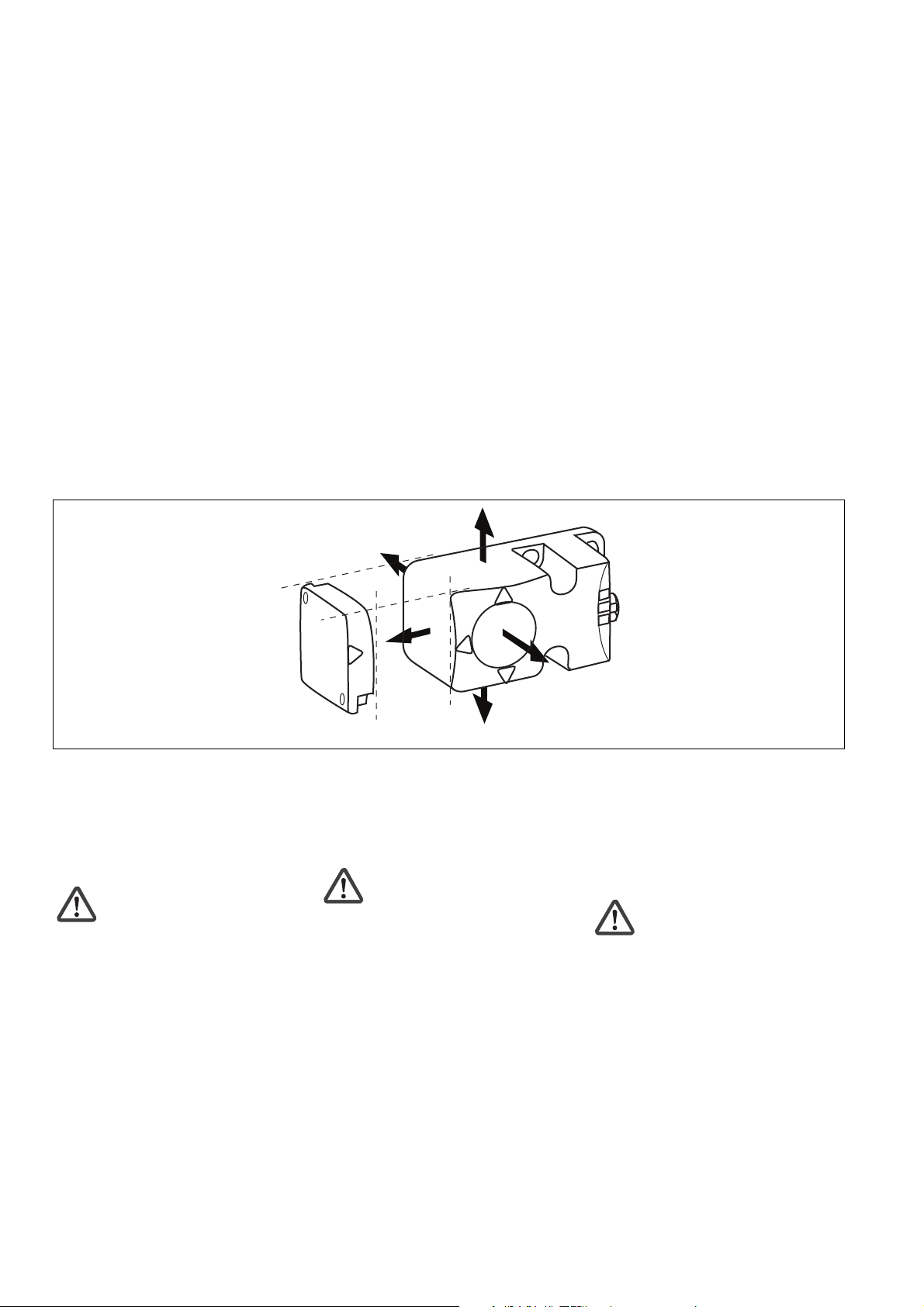
Montage
• Die Montagelage ist beliebig. Die aktiven
Flächen von Sicherheitsschalter und
Betätiger müssen jedoch parallel gegenüberliegend montiert werden:
Aktive Flächen PSEN cs2.1p/PSEN cs2.2p/Sensing faces, PSEN cs2.1p/PSEN cs2.2p/Superfici attive di PSEN cs2.1p/PSEN cs2.2p
• Wenn Sie Sicherheitsschalter und
Betätiger in Umbebung von elektrisch oder
magnetisch leitfähigem Material einbauen,
überprüfen Sie die Schaltabstände, da
Änderungen der typischen Werte zu
erwarten sind (Einbaubeispiel mit Schaltabständen siehe "Technischer Katalog
PSENmag und PSENcode").
Achtung!
Wenn Sie den Sicherheitsschalter
überbündig in elektrisch oder
magnetisch leitfähiges Material
einbauen kann sich außerdem der
Wert für den gesicherten Ausschaltabstand sar ändern.
• Befestigen Sie Sicherheitsschalter und
Betätiger ausschließlich mit Schrauben M5
mit flacher Kopfunterseite (z.B. M5Zylinderkopf- oder -Flachkopfschrauben).
Anzugsdrehmoment max. 1 Nm.
• Der Abstand zwischen zwei TransponderSystemen muss mindestens 40 cm
betragen.
Sicherheitsschalter und Betätiger
• keinen starken Stößen oder Schwingungen aussetzen
• nicht als Anschlag benutzen
Installation
• The unit can be installed in any position.
The sensing faces of safety switches and
actuators, however, must be positioned
opposite each other in parallel:
• If you install safety switches and actuators
in the vicinity of electrically or magnetically
conductive material, check the switching
distances, as changes can be expected
(for a typical installation with switching
distances, see the "PSENmag and
PSENcode technical catalogue").
Caution!
If you install the safety switch nonflush within electrically or
magnetically conductive material, the
value for the assured release
distance sar can also change.
• Safety switches and actuators should only
be secured using M5 screws with a flat
head (e.g. M5 cheese-head or pan head
screws). Torque setting, max. 1 Nm.
• The distance between two transponder
systems must be at least 40 cm.
Safety switch and actuator
• Do not expose to heavy shock or vibration
• Do not use as a limit stop
Montaggio
• La posizione di montaggio è indifferente.
Le superfici attive dell’interruttore di
sicurezza e dell’attuatore tuttavia devono
essere montate parallele una di fronte
all’altra:
• Se gli interruttori di sicurezza e gli
attuatori vengono installati nelle vicinanze
di materiale a conduzione elettrica o
magnetica, è necessario verificare le
distanze di commutazione poiché
possono verificarsi delle variazioni
(esempio di installazione con distanze di
commutazione: v. „Catalogo tecnico
PSENmag e PSENcode“).
Attenzione!
Se l’interruttore di sicurezza viene
installato all’interno di materiali a
conduzione elettrica o magnetica,
anche il valore della distanza di
disattivazione garantita sar può
variare.
• Gli interruttori di sicurezza e gli attuatori
devono essere fissati utilizzando viti M5 a
testa piatta (ad es. viti M5 cilindriche o a
testa piatta). Coppia di serraggio: max. 1
Nm.
• La distanza tra due sistemi a transponder
deve essere di almeno 40 cm.
L’interruttore di sicurezza e l’attuatore
• non devono essere esposti a choc o forti
vibrazioni
• non devono essere utilizzati come
finecorsa
- 2 -
Page 3
Justage
• Der Sicherheitsschalter kann nur mit dem
zugehörigen Betätiger PSEN cs2.1
verwendet werden.
• Prüfen Sie die Funktion immer mit einem
der zugelassenen Auswertegeräte.
• Die angegebenen Schaltabstände (siehe
technische Daten) gelten nur, wenn
Sicherheitsschalter und Betätiger parallel
gegenüberliegend montiert sind. Andere
Anordnungen können zu abweichenden
Schaltabständen führen. Beachten Sie den
maximal zulässigen Seiten- und Höhenversatz (siehe "Schaltabstände" und
"Max. Seiten- und Höhenversatz").
Adjustment
• The safety switch may only be used with a
corresponding PSEN cs2.1 actuator.
• Always test the function with one of the
approved evaluation devices.
• The stated switching distances (see
Technical details) only apply when the
safety switch and actuator are installed
facing each other in parallel. Switching
distances may deviate if other arrangements are used. Note the maximum
permitted lateral and vertical offset (see
"Switching distances" and "Max. lateral
and vertical offset").
Allineamento
• L’interruttore di sicurezza può essere
utilizzato solo con il corrispondente
attuatore PSEN cs2.1.
• Verificare sempre la funzionalità con un
dispositivo di controllo certificato.
• Le distanze di commutazione indicate (v.
Dati Tecnici) sono valide solo se
l’interruttore di sicurezza e l’attuatore
sono montati paralleli uno di fronte
all’altro. In caso di montaggio in altre
posizioni, le distanze di commutazione
possono variare. Rispettare l’offset
laterale e verticale massimo consentito
(v. „Distanze di commutazione“ e „Offset
laterale e verticale max.“).
Anschlüsse
Wichtig!
Die Farbkennzeichnung für die
Anschlussleitung gilt nur für die als
Zubehör erhältlichen Kabel von Pilz
Belegung des
8-pol. M12-Stiftsteckers/
Assignment of the
8-pin M12 male
connector/
Configurazione del
connettore a 8 poli
M12
Anschluss an Auswertegerät
Die Sicherheitsschalter können mit allen
zugelassenen plusschaltenden
zweikanaligen Auswertegeräten ohne
Querschlusserkennung angeschlossen
werden.
5
6
7
8
4
1
3
2
Connections
Important!
The colour marking for the connection
lead only applies for the cable that Pilz
supplies as an accessory
Collegamenti
Importante!
La codifica di colori per il cavo di
collegamento è valida solo per il cavo
disponibile come accessorio Pilz.
PIN Funktion/Function/Funzione Klemmenbezeichung/ Adernfarbe/Cable
Terminal designation/ colour/Colore del filo
Denominazione morsetti
1: Eingang Kanal 2/Input, channel 2/ S21 weiß/white/bianco
Canale di ingresso 2
2: +24 U
3: Ausgang Kanal 1/Output, channel 1/ 12 grün/green/verde
B
A1 braun/brown/marrone
Canale di uscita 1
4: Ausgang Kanal 2/Output, channel 2/ 22 gelb/yellow/giallo
Canale di uscita 2/
5: Melde-/Diagnoseausgang/Signal/diagnostic Y32 grau/grey/grigio
output/Uscita di segnalazione-diagnostica
6: Eingang Kanal 1/Input, channel 1/ S11 rosa/pink/rosa
Canale di ingresso 1
7: 0 V U
8: nicht anschließen/do not connect/ - rot/red/rosso
B
A2 blau/blue/blu
non collegare
Connection to evaluation device
The safety switches can be connected with
all permitted positive switching dual-channel
evaluation devices without detection of
shorts.
Collegamento al dispositivo di controllo
Gli interruttori di sicurezza possono essere
collegati a tutti i dispositivi di controllo che
accettano segnali positivi in ingresso, senza
riconoscimento del cortocircuito.
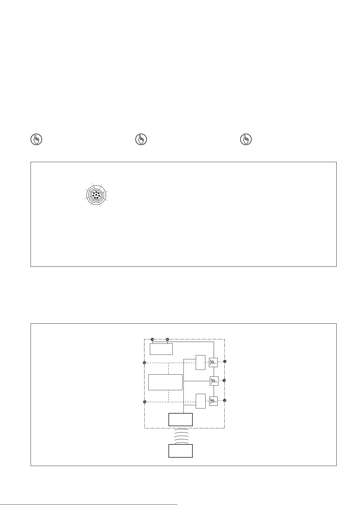
Blockschaltbild
Block diagram
U
B
A2
A1
Netzteil
Power supply
Alimentatore
S11
Teilbetätigungssperre
Partial operation lock
Blocco comando
parziale
S21
Empfänger
Receiver
Ricevitore
Betätiger
Actuator
Attuatore
Schema a blocchi
&
&
12
Y32
22
- 3 -
Page 4

Schaltabstände Switching distances Distanze di commutazione
Seitenversatz/Lateral offset/Offset laterale Höhenversatz/Vertical offset/
Seiten- und Höhenversatz
Lateral and vertical offset
Betätigungsrichtung frontal/Direction of actuation, front/
Senso di azionamento: frontale
Offset verticale
Betätigungsrichtung seitlich/Direction of actuation, side/
Senso di azionamento: laterale
Typischer Ausschaltabstand /Typical release distance/
Distanza di disattivazione tipica
Typischer Schaltabstand
so/Typical operating
distance so/Distanza di
commutazione tipica s
o
Versatz in mm/
Offset in mm/
Offset in mm
commutazione in mm
distance in mm/Distanza di
Schaltabstand in mm/Switching
046810-4-6-8-10
Hysterese/
Hysteresis/
Isteresi
10
5
0
10
5
0
Ansprechbereich/
Response range/
Campo di risposta
Ansprechbereich/
Response range/
Campo di
risposta
Schaltabstand
Switching distance
Distanza di commutazione
Typischer Ausschaltabstand /Typical release
distance/Distanza di
disattivazione tipica
-30
-40
20
10
0
Hysterese/
Hysteresis/
Isteresi
s
ar
s
ao
Offset laterale e verticale
Typischer Schaltabstand so/
Typical operating distance so/
Distanza di commutazione
tipica s
o
0 102030405060-10-20
Power /Fault
Safety Gate
Versatz in mm/
Offset in mm/
Offset in mm
Input
Ein/On/Acceso
Aus/Off/Spento
in mm/Distanza di commutazione in mm
20
10
0
Schaltabstand in mm/Switching distance
Betätigungsrichtung oben/unten/Direction of actuation
up/down/Senso di azionamento: dall’alto, dal basso
Typischer Ausschaltabstand /Typical release
distance/Distanza di
disattivazione tipica
Typischer Schaltabstand so/Typical operating
distance so/Distanza di commutazione tipica s
Versatz in mm/
Offset in mm/
Offset in mm
-40
-30
0 102030405060-10-20
20
10
0
Hysterese/
Hysteresis/
Isteresi
Ansprechbereich/
Response range/
Campo di
risposta
Gesicherter Ausschaltabstand S
max. 40 mm bei allen Höhen- und
Seitenversätzen
:
ar
Assured release distance S
max. 40 mm with all vertical and lateral
offsets
o
in mm/Distanza di commutazione in mm
Schaltabstand in mm/Switching distance
20
10
0
:
ar
Distanza di disattivazione garantita S
max. 40 mm per tutti gli offset laterali e
verticali
:
ar
- 4 -
Page 5

Inbetriebnahme
• Eingänge S11 und S21 mit 24 V DC
verbinden, bei Reihenschaltung mit den
Sicherheitsausgängen 12 und 22 des
Vorgängergeräts verbinden.
• Berechnung der max. Leitungslänge I
zwischen Auswertegerät und Sicherheitsschalter pro Kanal:
R
lmax
=
I
max
Rl / km
R
= max. Gesamtleitungswiderstand
lmax
Rl /km = Leitungswiderstand/km
(siehe Beispiel Technischer Katalog
PSENmag und PSENcode)
max
Commissioning
• Connect the inputs S11 and S21 with 24
V DC; for series connection connect with
safety outputs 12 and 22 of the previous
device.
• Calculating the max. cable runs I
between the evaluation device and the
safety switch, per channel:
R
lmax
=
I
max
Rl / km
R
= max. overall cable resistance
lmax
Rl /km = cable resistance/km
(see example PSENmag and PSENcode
technical catalogue )
max
Messa in funzione
• Collegare gli ingressi S11 ed S21 a 24 V
DC; per il collegamento in serie, collegare
con le uscite di sicurezza 12 e 22 del
dispositivo precedente.
• Calcolo della lunghezza max. del cavo I
tra dispositivo di controllo e interruttore di
sicurezza per canale:
R
lmax
=
I
max
Rl / km
R
= resistenza conduttore totale max.
lmax
Rl /km = resistenza conduttore/km
(esempio: v. Catalogo tecnico PSENmag
e PSENcode)
max
Einlernen des Betätigers
Erstmaliges Einlernen des Betätigers:
Der erste vom Sicherheitsschalter erkannte
Betätiger wird automatisch eingelernt, sobald
er in den Ansprechbereich gebracht wird.
PSEN cs2.1p:
Einlernen eines neuen Betätigers:
1. Bringen Sie den einzulernenden Betätiger
als einzigen Transponder in den Ansprechbereich des Sicherheitsschalters.
Sobald der Betätiger erkannt wird,
wechselt die LED "Safety Gate" auf gelbes
Blinklicht.
2. Nach einer Wartezeit von 20 s wechselt
die LED "Safety Gate" auf gelbes Blitzen.
Lösen Sie innerhalb der nächsten 120 s
durch Unterbrechen der Stromversorgung
einen Systemreset aus.
3. Nach Wiedereinschalten des Geräts ist der
Lernvorgang erfolgreich beendet und die
Anzahl noch erlaubter weiterer Lernvorgänge wird um 1 vermindert.
Wichtig!
Der Betätiger darf während des
Einlernvorgangs nicht entfernt werden.
Teaching in the actuator
Initially teaching in the actuator:
The first actuator detected by the safety
switch is automatically taught in as soon as it
is brought into the response range.
PSEN cs2.1p:
To teach in a new actuator:
1. Bring the actuator to be taught in into the
response range of the safety switch as the
only transponder. As soon as the actuator
is detected, the "Safety Gate" LED
switches over to yellow flashing light.
2. After a waiting period of 20 s has elapsed,
the "Safety Gate" LED switches over to
yellow flashes. Trigger a system reset in
the next 120 s by interrupting the power
supply.
3. After the device is switched back on, the
learning procedure has successfully
concluded and the number of permitted
additional learning procedures is reduced
by 1.
Important!
The actuator must not be removed
during the learning procedure.
Programmazione dell’attuatore
Prima programmazione dell’attuatore:
Il primo attuatore riconosciuto
dall’interruttore di sicurezza viene
programmato automaticamente non appena
viene a trovarsi nel campo di risposta.
PSEN cs2.1p:
Programmazione di un nuovo attuatore:
1. Posizionare l’attuatore da programmare
come transponder univoco nel campo di
risposta dell’interruttore di sicurezza. Non
appena l’attuatore viene riconosciuto, il
LED „Safety Gate“ comincia a
lampeggiare con luce gialla.
2. Dopo 20 s, il LED „Safety Gate“ emette
dei flash gialli. Entro i successivi 120 s,
eseguire un reset del sistema
interrompendo l’alimentazione.
3. Dopo aver riacceso il dispositivo, il
processo di programmazione è concluso
correttamente e il numero di
programmazioni ancora possibili
diminuisce di 1.
Importante!
Durante la programmazione
l’attuatore non deve essere rimosso.
Betrieb
Statusanzeigen:
• LED "POWER/Fault" leuchtet grün: Gerät
ist betriebsbereit
• LED "Safety Gate" leuchtet gelb: Betätiger
befindet sich im Ansprechbereich
• LED "Input" leuchtet gelb: Eingangskreise
sind geschlossen oder ein HIGH-Signal
liegt an
Fehleranzeige:
• LED "Input" blinkt gelb: nur ein Kanal des
Eingangskreises offen (Teilbetätigung)
Abhilfe: beide Kanäle des Eingangskreises
öffnen
• LED "POWER/Fault" leuchtet rot: Fehlermeldung.
An den LEDS "Safety Gate" und "Input"
werden Blinkcodes zur Fehlerdiagnose
ausgegeben (siehe Technischer Katalog
PSENmag und PSENcode).
Abhilfe: Fehler beheben und Stromversorgung unterbrechen.
Operation
Status indicators:
• "POWER/Fault" LED illuminates green:
The unit is ready for operation
• "Safety Gate" LED illuminates yellow:
Actuator is in the response range
• "Input" LED illuminates yellow: Input
circuits are closed or a HIGH signal is
present
Fault indicator:
• "Input" LED illuminates yellow: only one
channel of the input circuit open (partial
operation)
Remedy: both channels of the input circuit
open
• "POWER/Fault" LED illuminates red: Error
message.
Flashing codes for fault diagnosis are
output to the "Safety Gate" and "Input"
LEDs (see PSENmag and PSENcode
technical catalogue).
Remedy: Rectify fault and interrupt power
supply.
Funzionamento
Indicatori di stato:
• Il LED „POWER/Fault“ è acceso, luce
verde: il dispositivo è pronto per il
funzionamento
• Il LED „Safety Gate“ è acceso, luce gialla:
l’attuatore si trova nel campo di risposta
• Il LED „Input“ è acceso, luce gialla: i
circuiti di ingresso sono chiusi o è
presente un segnale High
Indicatori di errore:
• Il LED „Input“ lampeggia, luce gialla: solo
un canale del circuito di ingresso è aperto
(comando parziale)
Risoluzione: aprire entrambi i canali del
circuito di ingresso
• Il LED „POWER/Fault“ è acceso, luce
rossa: segnalazione di errore.
I LED „Safety Gate“ e „Input“ emettono
codici lampeggianti di diagnostica (v.
Catalogo tecnico PSENmag e
PSENcode).
Risoluzione: rimuovere l’errore e
interrompere l’alimentazione.
- 5 -
Page 6

Technische Daten
Technical Data
Dati tecnici
Elektrische Daten
Versorgungsspannung U
B
Spannungstoleranz
Leistungsaufnahme bei U
Max. Einschaltstrom an U
B
B
Schaltstrom
Schaltleistung pro Ausgang (12, 22,
Y32)
Max. Schaltfrequenz
Ausgangskontakte nach EN 954-1
(kurzschlussfest)
Sicherheitsausgänge (S)
Meldeausgang (S)
Max. Gesamtleitungswiderstand
R
im Eingangskreis
lmax
Max. Leitungskapazität an 12, 22
Leerlauf, PNOZ mit
Relaiskontakten
PNOZmulti, PNOZelog, PSS
Zeiten
Überbrückung bei
Spannungseinbrüchen
Einschaltverzögerung
nach Anlegen von U
Eingänge PSEN cs2.1p/PSEN cs2.2p
B
Betätiger PSEN cs2.1
Rückfallverzögerung
Eingänge PSEN cs2.1p/PSEN cs2.2p
Betätiger PSEN cs2.1
Testimpulse Sicherheitsausgänge
12, 22
Gleichzeitigkeit Kanal 1 und 2
Umweltdaten
EMV
Schockbeanspruchung
Schwingungen nach
EN 60947-5-2
Frequenz
Amplitude
Verschmutzungsgrad
Bemessungsisolationsspannung
Bemessungsstoßspannungsfestigkeit
Umgebungstemperatur
Mechanische Daten
Hysterese typ.
Gesicherter Schaltabstand s
ao
Gesicherter Ausschaltabstand sar*
Typischer Schaltabstand s
o
Anschlussart
Leitung
Schutzart
Gehäusematerial
Abmessungen siehe Abbildung
Gewicht
PSEN cs2.1p/PSEN cs2.2p
PSEN cs2.1
Electrical data
Supply voltage U
B
Voltage tolerance
Power consumption at U
Max. inrush current with U
B
B
Switching current
Breaking capacity per output (12,
22, Y32)
Max. switching frequency
Output contacts in accordance with
EN 954-1 (short circuit-proof)
safety outputs (N/O)
signal output (N/O)
Max. overall cable resistance
R
in input circuit
lmax
Max. line capacitance with 12,22
No-load, PNOZ with relay
contacts
PNOZmulti, PNOZelog, PSS
Times
Supply interruption before deenergisation
Switch-on delay
after applying U
Inputs, PSEN cs2.1p/PSEN cs2.2p
B
Actuator, PSEN cs2.1
Delay-on de-energisation
Inputs, PSEN cs2.1p/PSEN cs2.2p
Actuator, PSEN cs2.1
Test pulses safety outputs 12, 22
Simultaneity, channel 1/2
Environmental data
EMC
Shock stress
Vibration in accordance with
EN 60947-5-2
Frequency
Amplitude
Pollution degree
Rated insulation voltage
Rated impulse withstand voltage
Ambient temperature
Mechanical data
Hysteresis typ.
Assured operating distance s
ao
Assured release distance sar*
Typical operating distance s
o
Connection type
Cable
Protection type
Housing material
Dimensions, see graphic
Weight
PSEN cs2.1p/PSEN cs2.2p
PSEN cs2.1
Dati elettrici
Tensione di alimentazione U
B
Tolleranza di tensione
Potenza assorbita U
Corrente di inserzione max. U
B
B
Corrente di commutazione
Capacità di commutazione per
uscita (12, 22, Y32)
Max. frequenza di commutazione
Contatti di uscita secondo EN 954-1
(protez. cortocircuito)
uscite di sicurezza (NA)
uscita di segnalazione (NA)
Resistenza totale conduttore max.
R
nel circuito d’ingresso
lmax
Max.capacità conduttore su 12, 22
a vuoto, PNOZ con contatti
a relè
PNOZmulti, PNOZelog, PSS
Tempi
Ininfluenza per mancanza
tensione
Ritardo d’inserzione
dopo applicazione di U
Ingressi di PSEN cs2.1p/PSEN cs2.2p
B
Attuatore PSEN cs2.1
Ritardo di sgancio
Ingressi di PSEN cs2.1p/PSEN cs2.2p
Attuatore PSEN cs2.1
Impulsi di test uscite di sicurezza
12, 22
Simultaneità canali 1 e 2
Dati ambientali
Compatibilità elettromagnetica
Resistenza agli shock
Oscillazioni secondo
EN 60947-5-2
Frequenza
Ampiezza
Grado di contaminazione
Tensione di isolamento nominale
Tensione impulsiva nominale
Temperatura ambiente
Dati meccanici
Isteresi tip.
Distanza di commutazione garantita s
ao
Distanza di disattivazione garantita sar*
Distanza di commutazione tipica s
Tipo di colleg.
Conduttore
Grado di protezione
Materiale custodia
Dimensioni, v. illustrazione
Peso
PSEN cs2.1p/PSEN cs2.2p
PSEN cs2.1
24 V DC
-20 % ... +20 %
2 W
120 mA
500 mA
12 W
3 Hz
2
1
1 kOhm
40 nF
70 nF
20 ms
1 s
typ. 13 ms, max. 20 ms
typ. 45 ms, max. 100 ms
typ. 15 ms, max. 20 ms
typ. 30 ms, max. 260 ms
max. 300 µs
∞
EN 60947-5-3
30 g, 11 ms
10 ... 55 Hz
1 mm
3
250 V
4 kV
-25 ... +70 °C
3 mm
15 mm
40 mm
21 mm
o
8-pol. M12-Stiftstecker/
8 pin M12 connector/
connettore M12, 8 poli
LiYY 8 x 0,25 mm
2
IP67
Kunststoff/Plastic/Plastica:
PBTP VALOX RAL 1003
105 g
20 g
- 6 -
Page 7

Sicherheitstechnische Kenndaten der Sicherheitsausgänge
PL nach EN ISO 13849-1
Kategorie nach EN ISO 13849-1
SIL CL nach EN IEC 62061
PFH nach EN IEC 62061
SIL nach IEC 61511
PFD nach IEC 61511
tM in Jahren
Es gelten die 2007-02 aktuellen Ausgaben
der Normen
* gilt nicht bei überbündigem Einbau in
magnetisch oder elektrisch leitfähiges
Material
Safety-related characteristics of
the safety outputs
PL in accordance with
EN ISO 13849-1
Category in accordance with
EN ISO 13849-1
SIL CL in accordance with
EN IEC 62061
PFH in accordance with
EN IEC 62061
SIL in accordance with IEC 61511
PFD in accordance with IEC 61511
tM in years
Dati tecnici di sicurezza
PL secondo EN ISO 13849-1
Categoria secondo EN ISO 13849-1
SIL CL secondo EN IEC 62061
PFH secondo EN IEC 62061
SIL secondo IEC 61511
PFD secondo IEC 61511
tM in anni
The version of the standards current at
2007-02 shall apply
* does not apply when installed non-flush
within electrically or magnetically
conductive material
PL e (Cat. 4)
Cat. 4
SIL CL 3
4,10E-09
SIL 3
1,10E-04
20
Per le norme citate, sono applicate le
versioni in vigore al 2007-02
* non valido in caso di installazione
all’interno di materiale a conduzione
elettrica o magnetica
INFO
Bestellnummern und Zubehör finden
Sie im Technischen Katalog oder auf
unserer Internetseite www.pilz.com.
EG-Konformitätserklärung:
Diese(s) Produkt(e) erfüllen die Anforderungen der Richtlinie 2006/42/EG über
Maschinen des europäischen Parlaments
und des Rates.
Die vollständige EG-Konformitätserklärung
finden Sie im Internet unter www.pilz.com
Bevollmächtigter: Norbert Fröhlich,
Pilz GmbH & Co. KG, Felix-Wankel-Str. 2,
73760 Ostfildern, Deutschland
INFORMATION
Order numbers and accessories can
be found in the Technical Catalogue
or on our Internet site www.pilz.com.
EC Declaration of Conformity:
This (these) product(s) comply with the
requirements of Directive 2006/42/EC of the
European Parliament and of the Council on
machinery.
The complete EC Declaration of Conformity
is available on the Internet at www.pilz.com
Authorised representative: Norbert Fröhlich,
Pilz GmbH & Co. KG, Felix-Wankel-Str. 2,
73760 Ostfildern, Germany
INFORMATION
Vous trouverez les références et les
accessoires dans le catalogue
technique ou sur notre site
www.pilz.com.
Déclaration de conformité CE :
Ce(s) produit(s) satisfait (satisfont) aux
exigences de la directive 2006/42/CE
relative aux machines du Parlement
Européen et du Conseil.
Vous trouverez la déclaration de conformité
CE complète sur notre site internet
www.pilz.com
Représentant : Norbert Fröhlich,
Pilz GmbH & Co. KG, Felix-Wankel-Str. 2,
73760 Ostfildern, Allemagne
- 7 -
Page 8

Abmessungen in mm
Dimensions in mm Dimensioni in mm
PSEN cs2.1p/
PSEN cs2.2p
61
0
2
21,5
5,1
0
2
1
40
72
Mx1
5
,
5
45
0
4
12
0
3
PSEN cs2.1
4
0,5
30
11
40
5,3
40
30
74
Anschlussbeispiele
Einzelschaltung
PSEN cs2.1
PSEN cs2.2
Connection examples
Independent circuit
S11
12 22
I1
Esempi di collegamento
Circuito singolo
24 V
0 V
S21
PSEN cs2.1p
PSEN cs2.2p
A1
A2
I2
Auswertegerät
Evaluation device
Dispositivo di
controllo
A1
A2
Anschlussbeispiele mit Pilz-Auswertegeräten siehe technischer Katalog PSENmag und PSENcode / Example connections with Pilz
evaluation devices see PSENmag and PSENcode technical catalogue/Esempi di collegamento a dispositivi di controllo Pilz: v. Catalogo
tecnico PSENmag e PSENcode
- 8 -
Page 9

Reihenschaltung von 3 Sicherheitsschaltern
PSEN cs2.1p/PSEN cs2.2p
Betätiger/Actuator/
Attuatore PSENcode
Series connection of 3 PSEN cs2.1p/
PSEN cs2.2p safety switches
S11
Empfänger/Receiver/
Ricevitore PSENcode
S21
Collegamento in serie di 3 interruttori di
sicurezza PSEN cs2.1p/PSEN cs2.2p
24 V
0 V
PLC
A1
A2
Betätiger/Actuator/
Attuatore PSENcode
Betätiger/Actuator/
Attuatore PSENcode
12 22
S11
Empfänger/Receiver/
Ricevitore PSENcode
12 22
S11
Empfänger/Receiver/
Ricevitore PSENcode
12 22
I1
Auswertegerät
Evaluation device
Dispositivo di
controllo
I2
S21
S21
Y32
Y32
Y32
I1
A1
A2
I2
A1
A2
I3
A1
A2
Anschlussbeispiele mit Pilz-Auswertegeräten siehe technischer Katalog PSENmag und PSENcode / Example connections with Pilz
evaluation devices see PSENmag and PSENcode technical catalogue/Esempi di collegamento a dispositivi di controllo Pilz: v. Catalogo
tecnico PSENmag e PSENcode
Achtung!
Bei Reihenschaltung mehrerer
Geräte addiert sich die Rückfallverzögerung mit der Anzahl der
zwischengeschalteten Sicherheitsschalter.
Caution!
When connecting several units in
series, the delay-on de-energisation
time increases in direct proportion to
the number of interconnected safety
switches.
Attenzione!
Collegando in serie più dispositivi, il
ritardo allo sgancio aumenta in
proporzione al numero di interruttori
di sicurezza collegati.
- 9 -
Page 10

A
Pilz Ges.m.b.H., ✆ 01 7986263-0, Fax: 01 7986264
Fax: 09 3217571
DK
Pilz Skandinavien K/S, ✆ 74436332, Fax: 74436342
✆
03 88104000, Fax: 03 88108000
Fax: 01536 460866
J
Pilz Japan Co., Ltd., ✆ 045 471-2281, Fax: 045 471-2283
NL
Pilz Nederland, ✆ 0347 320477, Fax: 0347 320485
✆
229407594, Fax: 229407595
Fax: 031 8159542
✆
0224 2360180, Fax: 0224 2360184
D
Pilz GmbH & Co. KG, Sichere Automation, Felix-Wankel-Straße 2, 73760 Ostfildern, Deutschland, ✆ +49 711 3409-0, Fax: +49 711 3409-133,
E-Mail: pilz.gmbh@pilz.de
BR
Pilz do Brasil, ✆ 11 4337-1241, Fax: 11 4337-1242
FIN
I
Pilz ltalia Srl, ✆ 031 789511, Fax: 031 789555
PRC
SE
Pilz Skandinavien K/S, ✆ 0300 13990, Fax: 0300 30740
Pilz Skandinavien K/S, ✆ 09 27093700, Fax: 09 27093709
Pilz China Representative Office, ✆ 021 62494658, Fax: 021 62491300
USA
Pilz Automation Safety L.P., ✆ 734 354-0272, Fax: 734 354-3355
AUS
Pilz Australia, ✆ 03 95446300, Fax: 03 95446311
CH
E
Pilz lndustrieelektronik S.L., ✆ 938497433, Fax: 938497544
Pilz lndustrieelektronik GmbH, ✆ 062 88979-30, Fax: 062 88979-40
GB
IRL
MEX
NZ
Pilz New Zealand, ✆ 09- 6345-350, Fax: 09-6345-352
Pilz Ireland Industrial Automation, ✆ 021 4346535, Fax: 021 4804994
Pilz de Mexico, S. de R.L. de C.V., ✆ 55 5572 1300, Fax: 55 5572 4194
TR
Pilz Elektronik Güvenlik Ürünleri ve Hizmetleri Tic. Ltd. ¸Sti.,
B L
Pilz Automation Technology, ✆ 01536 460766,
ROK
www
Pilz Belgium, ✆ 09 3217570,
F
Pilz France Electronic,
P
Pilz Industrieelektronik S.L.,
Pilz Korea, ✆ 031 8159541,
www.pilz.com
- 10 -
Originalbetriebsanleitung/Original instructions/Notice originale
22 133-06-2009-12 Printed in Germany
 Loading...