

Page 1

21100-3FR-08
PSEN 2.1p-24 ATEX
4
D Betriebsanleitung
4
GB Operating instructions
4
F Manuel d'utilisation
Sicherheitsbestimmungen
• Das Gerät darf nur von Personen installiert
und in Betrieb genommen werden, die mit
dieser Betriebsanleitung und den geltenden Vorschriften über Arbeitssicherheit und
Unfallverhütung vertraut sind. Beachten
Sie die VDE- sowie die örtlichen Vorschriften, insbesondere hinsichtlich Schutzmaßnahmen.
• Entfernen Sie die Schutzkappe erst
unmittelbar vor Anschluss des Geräts
Bestimmungsgemäße Verwendung
Die Sicherheitsschalter PSEN 2.1p-24 sind
bestimmt für den Einsatz in Sicherheitsstromkreisen nach EN 60204-1 und
VDE 0113-1.
Der Sicherheitsschalter ist zugelassen für
den Einsatz in explosionsgefährdeten
Bereichen nach EN 60079-0: 2009,
EN 60079-15: 2010, EN 60079-31: 2009
Ex-Bereich Kategorie 3, Zone 2 (Gas)
II 3G Ex mc nAc IIC T6 und 22 (Stäube),
II 3D Ex mc tc IIIC T80°C IP67.
Der Sicherheitsschalter erfüllt EN 60947-5-3
nur zusammen mit dem Betätiger PSEN 2.120 und den folgenden Auswertegeräten:
• PNOZ e3.1p
• PNOZ e3vp 10s
• PNOZ e3vp 300s
• PNOZ e5.13p
• PNOZmulti
• Sicherheitssteuerung der Systemfamilie
PSS zusammen mit dem
Standardfunktionsbaustein SB066 (MBSPakete Exzenterpressen, Best.-Nr. 301
172; Hydraulikpressen, Best.-Nr. 301 173;
Transferstraßen, Best.-Nr. 301 175)
Safety Regulations
• The unit may only be installed and
operated by personnel who are familiar
with both these instructions and the
current regulations for safety at work and
accident prevention. Follow VDE and local
regulations especially as regards
preventative measures.
• Do not remove the protective cap until you
are about to connect the device.
Authorized applications
The safety switch PSEN 2.1p-24 are
intended for use in safety circuits in
accordance with EN 60204-1 and
VDE 0113-1.
The safety switch is approved for use in
potentially explosive atmospheres in
accordance with EN 60079-0: 2009,
EN 60079-15: 2010, EN 60079-31: 2009
Ex area category 3, zone 2 (gas)
II 3G Ex mc nAc IIC T6 and 22 (dust),
II 3D Ex mc tc IIIC T80°C IP67.
The safety switch meets the requirements of
EN 60947-5-3 only in conjunction with the
actuator PSEN 2.1-20 and the following
evaluation devices:
• PNOZ e3.1p
• PNOZ e3vp 10s
• PNOZ e3vp 300s
• PNOZ e5.13p
• PNOZmulti
• Safety control system from the PSS
system range in conjunction with the
standard function block SB066 (MBS
packages Eccentric Press, Order No. 301
172; Hydraulic Press, Order No. 301 173;
Transfer Line, Order No. 301 175)
Conseils préliminaires
• La mise en oeuvre de l'appareil doit être
effectuée par une personne spécialisée en
installations électriques, en tenant compte
des prescriptions des différentes normes
applicables (NF, EN, VDE..), notamment
au niveau des risques encourus en cas de
défaillance de l'équipement électrique.
• Veuillez retirer le cache de protection
avant de raccorder l’appareil.
Domaines d'utilisation
Les capteurs de sécurité PSEN 2.1p-24 sont
adaptés pour une utilisation dans les circuits
de sécurité selon les normes EN 60204-1 et
VDE 0113-1.
Le capteur de sécurité est homologué pour
une utilisation en atmosphères explosives
selon l'EN 60079-0:200-9, EN 60079-15:
2010, EN 60079-31: 2009 atmosphères
explosives, caté-gorie 3, zones 2 (gaz)
II 3G Ex mc nAc IIC T6 et 22 (poussières),
II 3D Ex mc tc IIIC T80°C IP67.
Le capteur de sécurité ne répond aux
exigences EN 60947-5-3 qu'en liaison avec
l'aimant PSEN 2.1-20 et les unités de
contrôles suivantes :
• PNOZ e3.1p
• PNOZ e3vp 10s
• PNOZ e3vp 300s
• PNOZ e5.13p
• PNOZmulti
• Automates de sécurité de la gamme PSS
avec le bloc fonction standard SB066
(Progiciel Presse Excentrique, réf. 301
172; Presses hydrauliques, réf. 301 173;
Ligne de transfert , réf.301 175)
Gerätebeschreibung
Zu den Sicherheitsschaltern PSEN 2.1p-24
gehört jeweils der Betätiger (Magnet)
PSEN 2.1-20.
Merkmale:
• 2 Reedkontakte (1 Öffner/1 Schließer)
• Wirkweise magnetisch
• Schaltspannung 30 V DC
• mit LED zur Anzeige des Schaltzustands
• ECOLAB-geprüft
Montage
• Die Montagelage ist beliebig. Sicherheitsschalter und Betätiger müssen jedoch
parallel gegenüberliegend montiert
werden.
• Sicherheitsschalter und Betätiger möglichst
nicht auf ferromagnetisches Material
montieren. Es sind Änderungen der
Schaltabstände zu erwarten. Benutzen Sie
in diesem Fall die Distanzplatte mit der
Bestell-Nr. 534 310.
• Befestigen Sie Sicherheitsschalter und
Betätiger ausschließlich mit Schrauben M4
mit flacher Kopfunterseite (z.B. M4Zylinderkopf- oder -Flachkopfschrauben).
Anzugsdrehmoment max. 1 Nm. Verwenden Sie Schrauben aus nicht magnetischem Material (z. B. Messing).
Description
The safety switch PSEN 2.1p-24 include the
actuator (magnet) PSEN 2.1-20.
Features:
• 2 reed contacts (1 N/C / 1 N/O contact)
• Magnetic operation
• Switching voltage 30 V DC
• with LED for switch status display
• ECOLAB tested
Installation
• The mounting position can be freely
selected. Safety switch and actuator must
be installed parallel and opposite each
other.
• If possible, do not install the safety switch
and actuator on ferromagnetic material.
Changes of the switch offsets are to be
anticipated. In this case, use the distance
plate order no. 534 310.
• The safety switch and actuator should only
be secured using M4 screws on which the
underside of the screw head is flat (e.g.
M4 cheese head or pan head screws).
Torque setting max. 1 Nm. Use screws
that are made from non-magnetic material
(e.g. brass).
- 1 -
Description de l'appareil
Les capteurs de sécurité PSEN 2.1p-24 sont
utilisés en liaison avec l'actionneur (aimant)
PSEN 2.1-20.
Particularités :
• 2 contacts reed (1 O/1F)
• Action magnétique
• Tension de commutation 30 V DC
• avec LED pour affichage status
• Contrôle effectué par ECOLAB
Installation
• Le sens de montage est indifférent. Le
capteur de sécurité et l'aimant doivent être
montés face à face de façon parallèle.
• Si possible, évitez d'installer le capteur et
l'aimant sur du matériel ferromagnétique.
Les distances de commutation peuvent
être modifiées. Utilisez dans ce cas un
support séparateur de réf. 534 310.
• Pour fixer le capteur de sécurité et
l’aimant, utilisez uniquement des vis M4
dont la tête présente une face inférieure
plate (par ex. une vis M4 cylindrique ou à
tête plate).
Couple de serrage maxi 1 Nm.
Utiliser des vis en métal non magnétiques
(par ex. laiton).
Page 2
• Der Abstand zwischen zwei Systemen aus
Sicherheitsschalter und Betätiger muss
mindestens 25 mm betragen.
Sicherheitsschalter und Betätiger
• von Eisenspänen fernhalten
• keinen starken Magnetfeldern aussetzen
• keinen starken Stößen oder Schwingungen aussetzen
• nicht als Anschlag benutzen
• Two systems consisting of a safety sensor
and a actuator must have a distance of at
least 25 mm.
Safety switch and actuator:
• keep away from iron cuttings
• do not expose to strong magnetic fields
• do not expose to strong shocks or vibration
• do not use as dead stop
• La distance minimale entre 2 systèmes
complets( capteur et aimant) doit être d'au
moins 25 mm.
Le capteur de sécurité et l'actionneur :
• doivent être éloignés des copeaux
métalliques
• ne doivent pas être exposés à des champs
magnétiques élevés
• ne doivent pas subir des chocs et
vibrations importants
• ne doivent pas être utilisés comme butée
Justage
• Der Sicherheitsschalter darf nur mit dem
zugehörigen Betätiger PSEN 2.1-20
verwendet werden.
• Prüfen Sie die Funktion immer mit einem
der zugelassenen Auswertegeräte.
• Die LED leuchtet bei unbetätigten Reedkontakten (Schutzeinrichtung geöffnet oder
Sicherheitsschalter und Betätiger falsch
justiert). Die LED befindet sich im Öffnerkreis des Sicherheitsschalters. Bei
betätigten Reedkontakten erlischt die LED.
• Die angegebenen Schaltabstände (siehe
technische Daten) gelten nur, wenn
Sicherheitsschalter und Betätiger parallel
gegenüberliegend montiert sind. Andere
Anordnungen können zu abweichenden
Schaltabständen führen. Beachten Sie den
maximal zulässigen Seiten- und Höhenversatz (siehe "Schaltabstände" und
"Max. Seiten- und Höhenversatz").
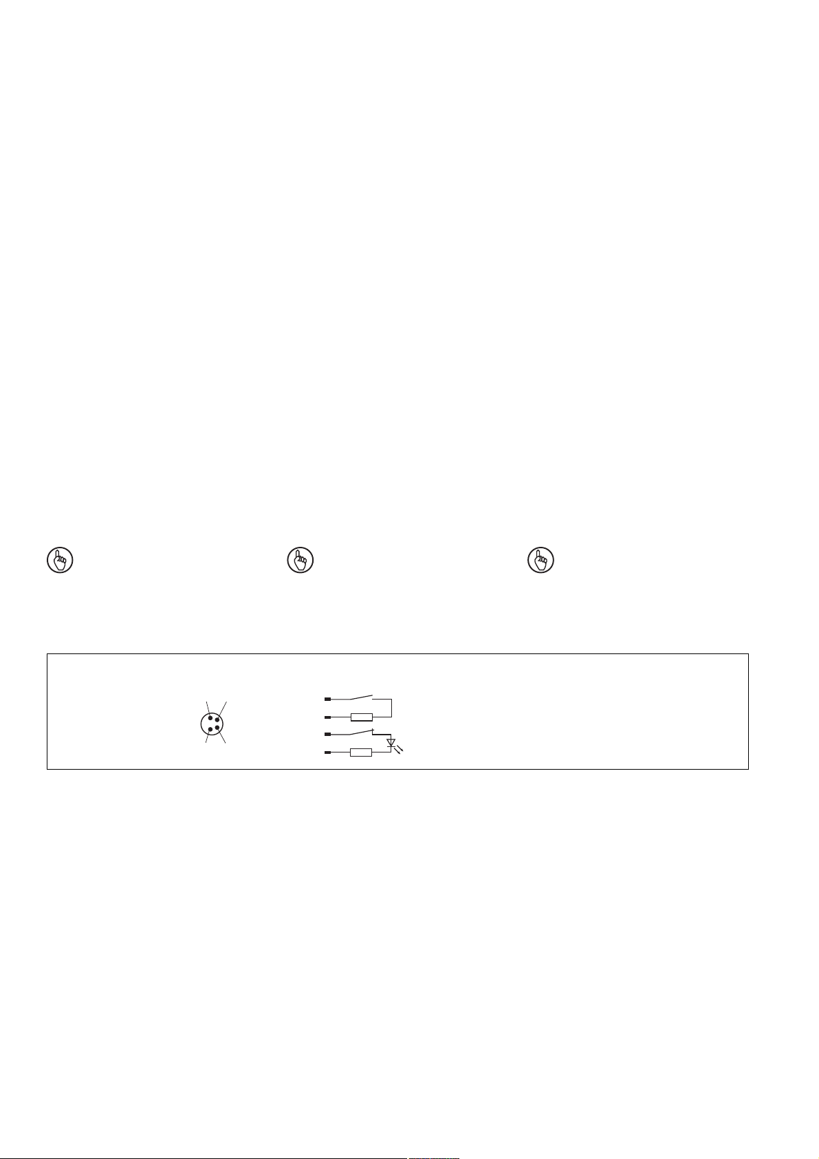
Anschlüsse
Wichtig: Die Farbkennzeichnung für
die Anschlussleitung gilt nur für die als
Zubehör erhältlichen Kabel von Pilz.
Adjustment
• The safety switch must only be used in
conjunction with its respective actuator
PSEN 2.1-20.
• Always check the functions with one of the
approved evaluation devices.
• The LED lights when the reed contacts
are not operated (safety device is open or
safety switch and actuator are adjusted
incorrectly). The LED is in the N/C contact
circuit of the safety sensor. When the
reed contacts are operated, the LED will
go out.
• The stated switch offsets (see technical
data) are only valid, when safety switch
and actuator are installed parallel and
opposite each other. Different layouts may
lead to deviating switching gaps. Please
note the maximum permissible lateral and
height offset (see "Switching distances"
and "Max. lateral and height offset").
Connections
Notice: The colour marking of the
connection cables only applies to
cables available from Pilz as an
accessory.
Ajustement
• Le capteur de sécurité ne peut être utilisé
qu'avec l'actionneur (aimant) PSEN 2.1-20.
• Testez la fonction uniquement avec une
des unités de contrôle autorisées.
• La LED est allumée quand les contacts
reed ne sont pas actionnés (protecteur
ouvert ou mauvais alignement du capteur
et de l'actionneur). La LED est insérée
dans le contact à ouverture du capteur de
sécurité. Quand les contacts Reed sont
actionnés, la LED s'éteint.
• Les distances de commutation indiquées
(voir caractéristiques techniques) ne sont
valables que si le capteur et l'actionneur
sont montés parallèlement face à face. Un
autre montage peut entraîner la
modfication des distances de
commutation. Veuillez noter les valeurs
des décalages latéraux et en hauteur
toléréés (voir "Distances de commutation"
et "décalage latéral max. et décalage en
hauteur max.").
Raccordement
Important : Les repérages des
couleurs ne sont valables que pour les
câbles fournis par Pilz.
Der Sicherheitsschalter ist in unbetätigtem
Zustand dargestellt
Belegung des
4pol. M8-Stiftsteckers/
Configuration of the 4pin M8 connector/
Repérage du
connecteur M8 4 br.
2
1
34
The safety switch is shown in not operated
mode.
PSEN 2.1p-24
1
2
3 +
4
Le capteur de sécurité est représenté en
position non actionnée.
- 2 -
Page 3
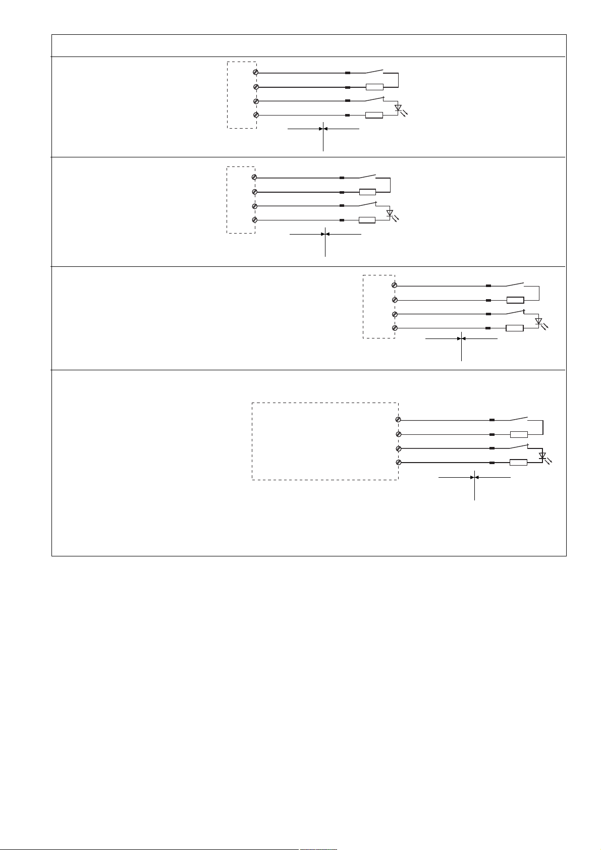
Anschluss an Auswertegerät
Connection to evaluation device Raccordement à l'unité de contrôle
• PNOZ e3.1p
• PNOZ e3vp 10s
• PNOZ e3vp 300s
• PNOZ e5.13p
• Beispiel für
Sicherheitssteuerung PSS
• Example of PSS
safety system
• Exemple pour
automate PSS
braun/brown/marron
S11
weiß/white/blanc
S12
blau/blue/
S23
schwarz/black/noir
S24
bleu
Nicht-Ex-Bereich/Non-Ex area/
Zone Non Ex
braun/brown/marron
A1
weiß/white/blanc
S32
blau/blue/
A1
schwarz/black/noir
S44
bleu
Nicht-Ex-Bereich/Non-Ex area/
Zone Non Ex
Taktausgang/Test pulse output/Sortie impulsionnelle
Eingang/Input/Entrée
Taktausgang/Test pulse output/Sortie impulsionnelle
Eingang/Input/
1
2
3
4
Ex-Bereich/Ex area/
Zone Ex
1
2
3
4
Ex-Bereich/Ex area/
Zone Ex
Entrée
Nicht-Ex-Bereich/Non-Ex area/
Zone Non Ex
braun/brown/marron
O 16
weiß/white/blanc
I 00
blau/blue/
O 17
schwarz/black/noir
I 01
bleu
1
2
3
4
Ex-Bereich/Ex area/
Zone Ex
• Beispiel für PNOZmulti
• Example of PNOZmulti
• Exemple pour PNOZmulti
I0, I1: Eingänge/Inputs/Entrées
T0, T1: Taktausgänge/Test pulse
outputs/Sorties impulsionnelle
Beachten Sie:
•
Schließerkontakt des PSEN an I0
anschlie-
ßen
• Öffnerkontakt des PSEN an I1 anschließen
Schutztür, Schaltertyp 2/Safety gate, switch type 2/
Protecteur mobile, type du capteure 2
Nicht-Ex-Bereich/Non-Ex area/
Zone Non Ex
Please note:
• Connect N/O contact from PSEN to I0
• Connect N/C contact from PSEN to I1
braun/brown/marron
T0
weiß/white/blanc
I0
blau/blue/
T1
schwarz/black/noir
I1
bleu
1
2
3
4
Ex-Bereich/Ex area/
Zone Ex
Important :
• Câblage des contact à fermeture (PSEN)
au I0
• Câblage des contact à overture (PSEN)
au I1
- 3 -
Page 4

ATEX Einbau- und Betriebsvorschriften (X)
WARNUNG!
Gefahr der Beschädigung durch
mechanische Belastung. Strom
führende Bauteile des Sicherheitsschalters im explosionsgefährdeten
Bereich können freigelegt werden.
Lebensgefahr!
- Schützen Sie die Kanten des
Bodens des Sicherheitsschalters vor
Schlägen. Dies kann z. B. durch eine
vollflächige Montage erfolgen (siehe
Montagebeispiel).
- Schützen Sie den Steckverbinder
des Sicherheitsschalters vor
Schlägen.
- Beachten Sie außerdem die
weiteren Angaben im Abschnitt
Montage.
ATEX installation and operating
regulations (X)
WARNING!
Risk of damage due to mechanical
load. Live components on the safety
switch in the potentially explosive
area may become exposed. Threat to
life!
- Protect the edges of the safety
switch base from shock. This can be
achieved by full face installation, for
example (see Installation example).
- Protect the plug-in connector on the
safety switch from shock.
- Please also refer to the additional
information in the Installation section.
Prescriptions d'installation et
d'exploitation ATEX (X)
AVERTISSEMENT !
Risque d'endommagement dû à une
charge mécanique. Des éléments
conducteurs du capteur de sécurité
situé en atmosphère explosive
peuvent se révéler. Danger de
mort !
- Protégez les côtés de la face
inférieure du capteur de sécurité
contre les chocs. Cette protection
peut être assurée par un montage
sur une surface plane (voir exemple
de montage).
- Protégez le connecteur du capteur
de sécurité contre les chocs.
- Tenez également compte des
autres indications du paragraphe
Montage.
Montagebeispiel:
Der Sicherheitsschalter ist vollständig auf
dem Untergrund montiert.
Die Kanten des Bodens des Sicherheitsschalters sind somit gegen Schläge
geschützt.
Installation example:
The full face of the safety switch is installed
on the subplate.
As a result, the edges of the safety switch
base are protected from shock.
Exemple de montage :
Le capteur de sécurité est entièrement monté
sur la face inférieure.
Les côtés de la face inférieure du capteur de
sécurité sont ainsi protégés contre les chocs.
- 4 -
Page 5

Schaltabstände/Switching distances/Distance de commutation
Seitenversatz/Lateral offset/
Höhenversatz/Height offset/
Décalage latéral
active area
aktive Fläche
surface active
Décalage en hauteur
Schaltabstand/Operating distance/
s
ar
s
ao
s
omin
= 26
= 8
= 0,5
Portee de travail
Ein/On/Marche
Aus/Off/Arrêt
Seiten- und Höhenversatz/Lateral and height offset/Décalage latéral et Décalage en hauteur
(Die angegebenen Werte sind gültig bei einer Temperatur von 20°C/The stated values are valid at a temperature of 20°C/
Les valeurs indiquées sont valables pour une température de 20°C.)
Gesicherter Schaltabstand Sao in mm/Assured operating distance Sao in mm/Portée de travail assurée S
Höhenversatz/Height offset/Décalage en hauteur
4,0
6,5
6,5
6,5
6,5
6,5
5,0
6,0
6,0
6,0
5,5
5,5
2,0
1,0
7,5
1,0
1,5
2,0
Décalage latéral
2,5
3,0
Seitenversatz/Lateral offset/
7,5
7,5
7,5
7,0
7,0
7,5
7,0
7,0
7,0
3,0
7,0
7,0
7,0
6,5
6,5
en mm
ao
Gesicherter Ausschaltabstand S
max. 26 mm bei allen Höhen- und Seiten-
:
ar
Assured release distance S
max. 26 mm at all lateral and height offsets
versätzen
Abmessungen in mm/Dimensions in mm/Dimensions en mm
9
36
22
8,5
6,5
13
PSEN 2.1p-24
26
10,6
M8x1
4,5
19
LED
PSEN 2.1-20
26
4,5
19
8,5
36
22
13
:
ar
Portée de déclenchement assurée S
max. 26 mm pour tous les décalages latéral
:
ar
et les décalages en hauteur
- 5 -
Page 6

Technische Daten
Technical Data
Caractéristiques techniques
Technische Daten
ATEX-Zulassung
ATEX-Kategorie Gas
ATEX-Kategorie Staub
Einsatzbereich
Hysterese typ.
PSEN 2.1-20
Schaltabstände
Gesicherter Schaltabstand s
Min. Schaltabstand s
Gesicherter Ausschaltabstand s
a
omin
ar
Schaltspannung
Innenwiderstand
Max. Schaltstrom Sicherheits-
kontakte
Max. Schaltleistung Sicherheits-
kontakte
Max. Schaltfrequenz
Betätiger
Umgebungstemperatur
Schwingungen nach EN 60947-5-2
Frequenz
Amplitude
EMV
Schockbeanspruchung
Verschmutzungsgrad
Bemessungsisolationsspannung
Bemessungsstoßspannungs-
festigkeit
Anschlussart
Leitung
Schutzart
Gehäusematerial
Abmessungen
Sicherheitsschalter
Höhe
Breite
Tiefe
Betätiger
Höhe
Breite
Tiefe
Gewicht
Sicherheitsschalter
Betätiger
Sicherheitstechnische Kenndaten
B10d nach EN ISO 13849-1 und
EN IEC 62061
Lambdad/Lambda nach
EN IEC 62061
Technical data
ATEX approval
ATEX category Gas
ATEX category Dust
Application area
Hysteresis typ.
PSEN 2.1-20
Switching distances
Assured operating distance s
Min. operating distance s
Assured release distance s
ao
omin
ar
Switching voltage
Internal resistance
Max. switching current for safety
contacts
Max. breaking capacity for safety
contacts
Max. switching frequency
Actuator
Ambient temperature
Vibration to EN 60947-5-2
Frequency
Amplitude
EMC
Shock stress
Pollution degree
Rated insulation voltage
Rated impulse withstand voltage
Connection type
Cable
Protection type
Housing material
Dimensions
Safety switch
Height
Width
Depth
Actuator
Height
Width
Depth
Weight
Safety switch
Actutator
Safety-realted characteristic
data
B10d in accordance with
EN ISO 13849-1 and EN IEC 62061
Lambdad/Lambda in accordance with
EN IEC 62061
Caractéristiques techniques
Homologation ATEX
ATEX catégorie gaz
ATEX catégorie poussière
Champ d'application
Hystérésis env.
PSEN 2.1-20
Distances de commutation
Portée de travail assurée s
Portée de travail min. s
Portée de déclenchement assurée s
ao
omin
ar
Tension de commutation
Résistance interne
Courant max. de commutation des
contacts de sécurité
Puissance max. de commutation des
contacts de sécurité
Fréquence de commutation max.
Actionneur
Température ambiante
Vibrations selon EN 60947-5-2
Fréquence
Amplitude
CEM
Résistance aux chocs
Niveau d'encrassement
Tension assignée d'isolement
Tension assignée de tenue aux
chocs
Type de connection
Câble
Degré de protection
Matériau du boîtier
Dimensions
Capteur de sécurité
Hauteur
Largeur
Profondeur
Actionneur
Hauteur
Largeur
Profondeur
Poids
Capteur de sécurité
Actionneur
Caractéristiques techniques
de sécurité
B10d selon EN ISO 13849-1 et
EN IEC 62061
Lambdad/Lambda selon
EN IEC 62061
SEV 12 ATEX 0121 X
II 3G Ex mc nAc IIC T6
II 3D Ex mc tc IIIC T80°C IP67
X: -25 °C < ta < +55 °C
6 mm
8 mm
0,5 mm
26 mm
24 V DC
100 Ohm
10 mA
0,3 W
1 Hz
PSEN 2.1-20
-25 ... +55 °C
10 ... 55 Hz
1 mm
EN 60947-5-3
30 g, 11 ms
3
25 V
0,33 kV
4pol. M8-Stiftstecker/
4-pin M8 connector/
connecteur M8, 4 br.
LiYY 4 x 0,25 mm
2
IP65/IP67
PC
45 mm
26 mm
13 mm
36 mm
26 mm
13 mm
15 g
20 g
2.000.000
0,90
Es gelten die 2012-09 aktuellen Ausgaben
der Normen.
INFO
Bestellnummern und Zubehör finden
Sie im Technischen Katalog oder auf
unserer Internetseite www.pilz.com.
The version of the standards current at
2012-09 shall apply.
INFORMATION
Order numbers and accessories can
be found in the Technical Catalogue or
on our Internet site www.pilz.com.
- 6 -
Se référer à la version des normes en vigeur
au 2012-09.
INFORMATION
Vous trouverez les références et les
accessoires dans le catalogue
technique ou sur notre site
www.pilz.com.
Page 7

EG-Konformitätserklärung:
Diese(s) Produkt(e) erfüllen die Anforderungen der Richtlinie 2006/42/EG über Maschinen und der Richtlinie 94/9/EG (ATEX) des
europäischen Parlaments und des Rates.
Die vollständige EG-Konformitätserklärung
finden Sie im Internet unter www.pilz.com
Bevollmächtigter: Norbert Fröhlich,
Pilz GmbH & Co. KG, Felix-Wankel-Str. 2,
73760 Ostfildern, Deutschland
EC Declaration of Conformity:
This product/these products meet the
requirements of the directive 2006/42/EC for
machinery and directive 94/9/EC (ATEX) of
the European Parliament and of the Council.
The complete EC Declaration of Conformity
is available on the Internet at www.pilz.com
Authorised representative: Norbert Fröhlich,
Pilz GmbH & Co. KG, Felix-Wankel-Str. 2,
73760 Ostfildern, Germany
Déclaration de conformité CE :
Ce(s) produit(s) satisfait (satisfont) aux
exigences de la directive 2006/42/CE
concernant les machines et à la directive
94/9/CE (ATEX) du Parlement européen et
du Conseil.
Vous trouverez la déclaration de conformité
CE complète sur notre site internet
www.pilz.com
Représentant : Norbert Fröhlich,
Pilz GmbH & Co. KG, Felix-Wankel-Str. 2,
73760 Ostfildern, Allemagne
- 7 -
Page 8

Technischer Support
+49 711 3409-444 +49 711 3409-444
...
In vielen Ländern sind wir durch
unsere Tochtergesellschaften und
Handelspartner vertreten.
Nähere Informationen entnehmen
Sie bitte unserer Homepage oder
nehmen Sie Kontakt mit unserem
Stammhaus auf.
Technical support
... ...
In many countries we are
represented by our subsidiaries
and sales partners.
Please refer to our Homepage
for further details or contact our
headquarters.
Assistance technique
+49 711 3409-444
Nos filiales et partenaires
commerciaux nous représentent
dans plusieurs pays.
Pour plus de renseignements,
consultez notre site internet ou
contactez notre maison mère.
- 8 -
www
www.pilz.com
Pilz GmbH & Co. KG
Felix-Wankel-Straße 2
73760 Ostfildern, Germany
Telephone: +49 711 3409-0
Telefax: +49 711 3409-133
E-Mail: pilz.gmbh@pilz.de
Originalbetriebsanleitung/Original instructions/Notice originale
21100-3FR-08-2012-11 Printed in Germany
 Loading...