

Page 1
21 098-3FR-08
4 D Betriebsanleitung
4 GB Operating instructions
4 F Manuel d'utilisation
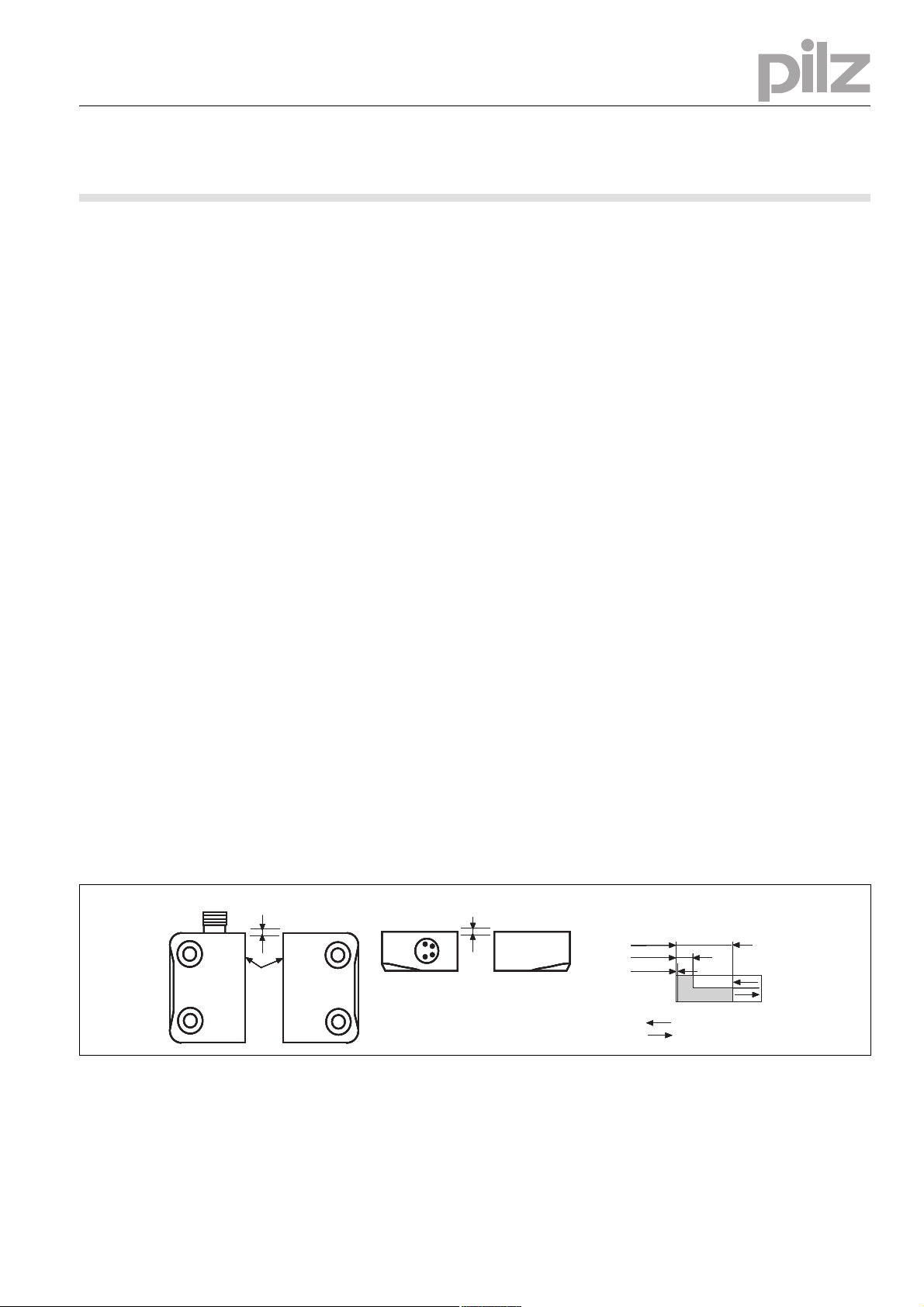
Seitenversatz/Lateral offset/
Décalage latéral
Höhenversatz/Height offset/
Décalage en hauteur
aktive Fläche
active area
surface active
Schaltabstand/Operating distance/
Portee de travail
s
ao
= 8
s
ar
= 26
Ein/On/Marche
Aus/Off/Arrêt
s
omin
= 0,5
Seitenversatz/Lateral offset/
Décalage latéral
Höhenversatz/Height offset/
Décalage en hauteur
aktive Fläche
active area
surface active
Schaltabstand/Operating distance/
Portee de travail
s
ao
= 8
s
ar
= 26
Ein/On/Marche
Aus/Off/Arrêt
s
omin
= 0,5
Seitenversatz/Lateral offset/
Décalage latéral
Höhenversatz/Height offset/
Décalage en hauteur
aktive Fläche
active area
surface active
Schaltabstand/Operating distance/
Portee de travail
s
ao
= 8
s
ar
= 26
Ein/On/Marche
Aus/Off/Arrêt
s
omin
= 0,5
Seitenversatz/Lateral offset/
Décalage latéral
Höhenversatz/Height offset/
Décalage en hauteur
aktive Fläche
active area
surface active
Schaltabstand/Operating distance/
Portee de travail
s
ao
= 8
s
ar
= 26
Ein/On/Marche
Aus/Off/Arrêt
s
omin
= 0,5
Seitenversatz/Lateral offset/
Décalage latéral
Höhenversatz/Height offset/
Décalage en hauteur
aktive Fläche
active area
surface active
Schaltabstand/Operating distance/
Portee de travail
s
ao
= 8
s
ar
= 26
Ein/On/Marche
Aus/Off/Arrêt
s
omin
= 0,5
PSEN 1.1p-23 ATEX
21 098-3FR-08PSEN 1.1p-23 ATEX
Sicherheitsschalter PSEN 1.1p-23
1392980363
Der Sicherheitsschalter erfüllt Forderungen der
EN 60204-1 und IEC 60204-1.
Der Sicherheitsschalter ist zugelassen für den
Einsatz in explosionsgefährdeten Bereichen
nach EN 60079-0: 2010, EN 60079-15: 2011,
EN 60079-31: 2009 Ex-Bereich Kategorie 3,
Zone 2 (Gas) II 3G Ex nCc IIC T6 X und 22
(Stäube), II 3D Ex tc IIIC T80°C X IP67.
Der Sicherheitsschalter erfüllt EN 60947-5-3
nur zusammen mit dem Betätiger PSEN 1.1-20
und hierfür zugelassenen Auswertegeräten.
Schließen Sie den Sicherheitsschalter nur an
Auswertegeräte an, die im Abschnitt "Anschlüsse" aufgeführt sind.
Zu Ihrer Sicherheit
547263243
Installieren und nehmen Sie das Gerät nur
dann in Betrieb, wenn Sie diese Betriebsanleitung gelesen und verstanden haben und
Sie mit den geltenden Vorschriften über Arbeitssicherheit und Unfallverhütung vertraut
sind.
Beachten Sie die VDE- sowie die örtlichen
Vorschriften, insbesondere hinsichtlich
Schutzmaßnahmen
Durch Öffnen des Gehäuses oder eigen-
mächtige Umbauten erlischt jegliche Gewährleistung.
777809547
Entfernen Sie die Schutzkappe erst unmittel-
bar vor Anschluss des Geräts.
Gerätemerkmale
510482059
Zum Sicherheitsschalter gehören die Betäti-
ger PSEN 1.1-20
510237579
2 Sicherheitskontakte (Schließer)
510312331
gesicherter Schaltabstand: 8,0 mm
gesicherter Ausschaltabstand: 26,0 mm
510316939
eckige Bauform
510321547
Wirkweise magnetisch
510477451
Schaltspannung 24 V DC
Schaltabstände Operating distances Distances de commutation
Safety switch PSEN 1.1p-23
The safety switch meets the requirements of
EN 60204-1 and IEC 60204-1.
The safety switch is approved for use in potentially explosive atmospheres in accordance
with EN 60079-0: 2010, EN 60079-15: 2011, EN
60079-31: 2009 Ex area category 3, zone 2
(gas) II 3G Ex nCc IIC T6 X and 22 (dust), II 3D
Ex tc IIIC T80°C X IP67.
The safety switch only complies with
EN 60947-5-3 in conjunction with the actuator
PSEN 1.1-20 and its approved evaluation devices.
The safety switch should only be connected to
the evaluation devices listed under "Connections".
For your safety
Only install and commission the unit if you
have read and understood these operating
instructions and are familiar with the applicable regulations for health and safety at work
and accident prevention.
Ensure VDE and local regulations are met,
especially those relating to safety.
Any guarantee is rendered invalid if the hous-
ing is opened or unauthorised modifications
are carried out.
Do not remove the protective cap until you
are just about to connect the unit.
Unit features
The actuators PSEN 1.1-20 belong to the
safety switch
2 safety contacts (N/O)
Assured operating distance: 8,0 mm
Assured release distance: 26,0 mm
Square design
Works magnetically
Switching voltage 24 VDC
Capteur de sécurité PSEN 1.1p-23
Le capteur de sécurité satisfait aux exigences
de l'EN 60204-1 et de la CEI 60204-1.
Le capteur de sécurité est homologué pour une
utilisation en atmosphères explosives selon
l'EN 60079-0:2010, EN 60079-15: 2011, EN
60079-31: 2009 atmosphères explosives, catégorie 3, zones 2 (gaz) II 3G Ex nCc IIC T6 X et
22 (poussières), II 3D Ex tc IIIC T80°C X IP67.
Le capteur de sécurité est conforme à la norme
EN 60947-5-3 uniquement lorsqu'il est utilisé
avec l'actionneur PSEN 1.1-20 et les unités de
contrôle spécialement homologuées à cet effet.
Ne raccordez le capteur de sécurité qu'aux unités de contrôle indiquées dans le chapitre
« Raccordements ».
Pour votre sécurité
Vous n'installerez l'appareil et ne le mettrez
en service qu'après avoir lu et compris le
présent manuel d'utilisation et vous être familiarisé avec les prescriptions en vigueur
sur la sécurité du travail et la prévention des
accidents.
Respectez les normes locales ou VDE, particulièrement en ce qui concerne la sécurité.
L'ouverture de l'appareil ou sa modification
annule automatiquement la garantie.
Veuillez retirer le cache de protection avant
de raccorder l'appareil.
Caractéristiques de l'appareil
Les actionneurs PSEN 1.1-20 sont associés
au capteur de sécurité.
2 contacts de sécurité (contacts à fermeture)
Distance de commutation de sécurité : 8,0
mm
Distance de déclenchement de sécurité :
26,0 mm
architecture rectangulaire
actionnement magnétique
Tension commutée 24 V DC
- 1 -
Page 2
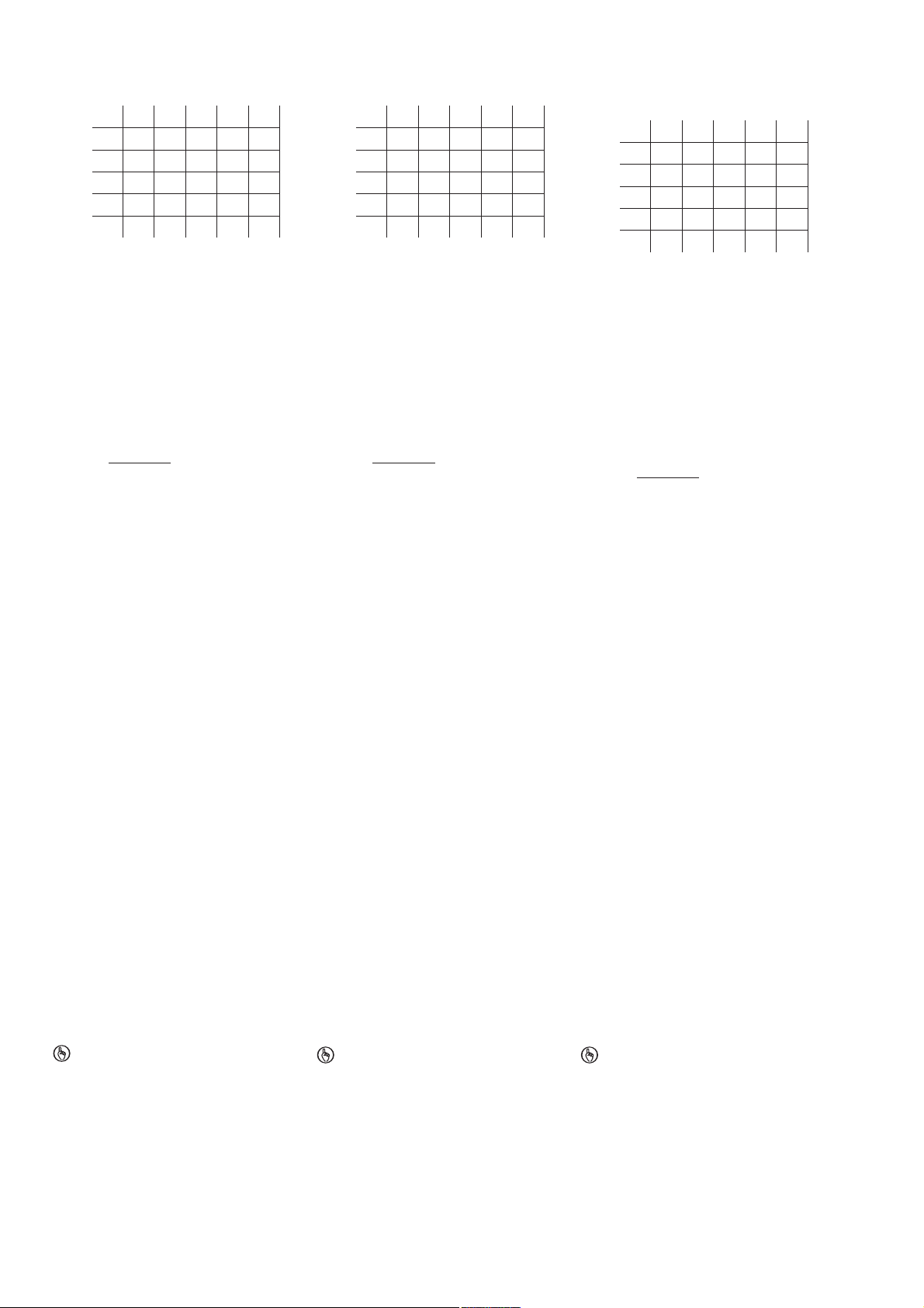
Seiten- und Höhenversatz
5,0
3,0
1,5
1,0
2,0
2,5
3,02,01,0 4,0
6,07,07,57,5 6,5
6,07,07,57,5 6,5
6,07,07,07,5 6,5
6,5
7,07,0
7,07,0
Höhenversatz/Height offset/
Décalage en hauteur
Seitenversatz/Lateral
offset/Décalage latéral
6,5
6,5
6,5
5,5
5,5
5,0
3,0
1,5
1,0
2,0
2,5
3,02,01,0 4,0
6,07,07,57,5 6,5
6,07,07,57,5 6,5
6,07,07,07,5 6,5
6,5
7,07,0
7,07,0
Höhenversatz/Height offset/
Décalage en hauteur
Seitenversatz/Lateral
offset/Décalage latéral
6,5
6,5
6,5
5,5
5,5
5,0
3,0
1,5
1,0
2,0
2,5
3,02,01,0 4,0
6,07,07,57,5 6,5
6,07,07,57,5 6,5
6,07,07,07,5 6,5
6,5
7,07,0
7,07,0
Höhenversatz/Height offset/
Décalage en hauteur
Seitenversatz/Lateral
offset/Décalage latéral
6,5
6,5
6,5
5,5
5,5
5,0
3,0
1,5
1,0
2,0
2,5
3,02,01,0 4,0
6,07,07,57,5 6,5
6,07,07,57,5 6,5
6,07,07,07,5 6,5
6,5
7,07,0
7,07,0
Höhenversatz/Height offset/
Décalage en hauteur
Seitenversatz/Lateral
offset/Décalage latéral
6,5
6,5
6,5
5,5
5,5
5,0
3,0
1,5
1,0
2,0
2,5
3,02,01,0 4,0
6,07,07,57,5 6,5
6,07,07,57,5 6,5
6,07,07,07,5 6,5
6,5
7,07,0
7,07,0
Höhenversatz/Height offset/
Décalage en hauteur
Seitenversatz/Lateral
offset/Décalage latéral
6,5
6,5
6,5
5,5
5,5
5,0
3,0
1,5
1,0
2,0
2,5
3,02,01,0 4,0
6,07,07,57,5 6,5
6,07,07,57,5 6,5
6,07,07,07,5 6,5
6,5
7,07,0
7,07,0
Höhenversatz/Height offset/
Décalage en hauteur
Seitenversatz/Lateral
offset/Décalage latéral
6,5
6,5
6,5
5,5
5,5
R
lmax
- R
i
Rl / km
I
max
=
R
lmax
- R
i
Rl / km
I
max
=
R
lmax
- R
i
Rl / km
I
max
=
880601995
Gesicherter Schaltabstand S
in mm
ao
Lateral and vertical offset
Assured operating distance Sao in mm
Décalage latéral et en hauteur
Distance de commutation de sécurité Sao en
mm
Gesicherter Ausschaltabstand S
Max. 26 mm bei allen Höhen- und Seitenver-
sätzen
Alle Angaben in mm. Die angegebenen Werte
sind gültig bei einer Temperatur von 20 °C.
Verdrahtung
492354955
Beachten Sie:
Angaben im Abschnitt „Technische Daten“
unbedingt einhalten.
Berechnung der max. Leitungslänge I
Eingangskreis des Auswertegerätes:
Beachten Sie bei Einsatz von Auswertegerä-
ten mit rückfallverzögerten Kontakten:
– Verzögerungszeit ≤ 30 s: die rückfallverzö-
– Verzögerungszeit ≥ 30 s: die rückfallverzö-
Überprüfen Sie in folgenden Fällen vor Inbe-
triebnahme die Funktion Querschlusserken-
nung:
– Bei Auswertegeräten mit Versorgungs-
– Bei Auswertegeräten mit Versorgungs-
– Wie Sie die Querschlussprüfung durchfüh-
Anschlüsse Connections Raccordements
Anschlussbelegung Terminal assignment Repérage des broches
Der Sicherheitsschalter ist in unbetätigtem Zustand dargestellt.
:
ar
im
max
= max. Gesamtleitungswiderstand
R
lmax
(s. techn. Daten des Auswertegeräts)
Ri = Innenwiderstand Sensor (s. techn. Daten Sensor)
/ km = Leitungswiderstand/km des Ka-
R
l
bels (s. techn. Daten Kabelhersteller)
gerten Kontakte genügen den Anforderungen der Kategorie 3 gemäß EN 954-1 bzw.
den Anforderungen an PDF mit Einfehlersicherheit (PDF-S).
gerten Kontakte genügen den Anforderungen der Kategorie 1 gemäß EN 954-1 bzw.
den Anforderungen an PDF mit Zuverlässigkeit durch besonderes Design (PDF-D).
spannung DC: Gesamtleitungswiderstand
≥ 15 Ohm pro Kanal
spannung AC: Gesamtleitungswiderstand
≥ 25 Ohm pro Kanal
ren müssen, entnehmen Sie der entsprechenden Bedienungsanleitung des
Auswertegeräts.
777658251
WICHTIG
Die Farbkennzeichnung für die Anschlussleitung gilt nur für die als Zubehör erhältlichen Kabel von Pilz.
Assured release distance S
Max. 26 mm with all vertical and lateral off-
:
ar
sets
All values in mm. The stated values are valid at
a temperature of 20 °C.
Wiring
Note:
Information given in the “Technical details”
must be followed.
Calculation of the max. cable length l
the input circuit of the evaluation device:
= Max. overall cable resistance (see
R
lmax
max
in
evaluation device's techn. details)
Ri = Internal sensor resistance (see sensor's
techn. details)
/ km = Cable resistance/km (see cable
R
l
manufacturer's techn. details)
When using evaluation devices with delay-on
de-energisation contacts, please note:
– Delay time ≤ 30 s: Delay-on de-energisation
contacts satisfy the requirements of Category 3 in accordance with EN 954-1 and
the requirements of a PDF with single-fault
tolerance (PDF-S).
– Delay time ≥ 30 s: Delay-on de-energisa-
tion contacts satisfy the requirements of
Category 1 in accordance with EN 954-1
and the requirements of a PDF with designed reliability (PDF-D).
In the following cases, check the function
that detects shorts across contacts prior to
commissioning:
– On evaluation devices with DC supply
voltage: Overall cable resistance ≥ 15
Ohms per channel
– On evaluation devices with AC supply volt-
age: Overall cable resistance ≥ 25 Ohms
per channel
– For details of how to perform the test for
shorts across the contacts, please refer to
the operating manual for the relevant evaluation device.
NOTICE
The colour marking for the connection lead
only applies for the cable that Pilz supplies
as an accessory.
The safety switch is shown in an unoperated
condition.
- 2 -
Distance de déclenchement de sécurité S
max. 26 mm pour tous les décalages laté-
ar
raux et en hauteur
Toutes les dimensions sont en mm. Les valeurs
indiquées sont valables pour une température
de 20 °C.
Câblage
Important :
Respecter impérativement les données indi-
quées dans la partie « Caractéristiques tech-
niques ».
Calcul de la longueur de câble max. I
le circuit d'entrée de l'unité de contrôle :
= résistance max. de l'ensemble du
R
lmax
max
sur
câblage (voir les caractéristiques techniques de l'unité de contrôle)
Ri = résistance interne du capteur (voir caractéristiques techniques du capteur)
/ km = résistance du câble/km (voir ca-
R
l
ractéristiques techniques du fabricant du
câble)
Important lors de l'utilisation d'unités de con-
trôle avec contacts temporisés à la retombée
:
–Temporisation ≤ 30 s : les contacts tempo-
risés à la retombée satisfont aux exigences de la catégorie 3 selon l'EN 954-1, et/
ou aux exigences des PDF avec sécurité
de défaut unique (PDF-S).
– Temporisation > 30 s : les contacts tempo-
risés à la retombée satisfont aux prescriptions de la catégorie 1 selon l'EN 954-1, et/
ou aux prescriptions des PDF avec une
fiabilité obtenue grâce à un design particulier (PDF-D).
Vérifiez dans les cas suivants avant la mise
en service la fonction détection des courts-
circuits :
– Pour des unités de contrôle avec tension
d'alimentation DC : résistance de l'ensemble du câblage ≥ 15 ohm par canal
– Pour des unités de contrôle avec tension
d'alimentation AC : résistance de l'ensemble du câblage ≥ 25 ohm par canal
– Consultez le manuel d'utilisation de l'unité
de contrôle pour connaître la manière
d'exécuter le contrôle des courts-circuits.
IMPORTANT
Le marquage de couleur du câble de raccordement est uniquement valable pour les
câbles Pilz disponibles en tant qu'acces-
soires.
Le capteur de sécurité est représenté en position de repos.
:
Page 3
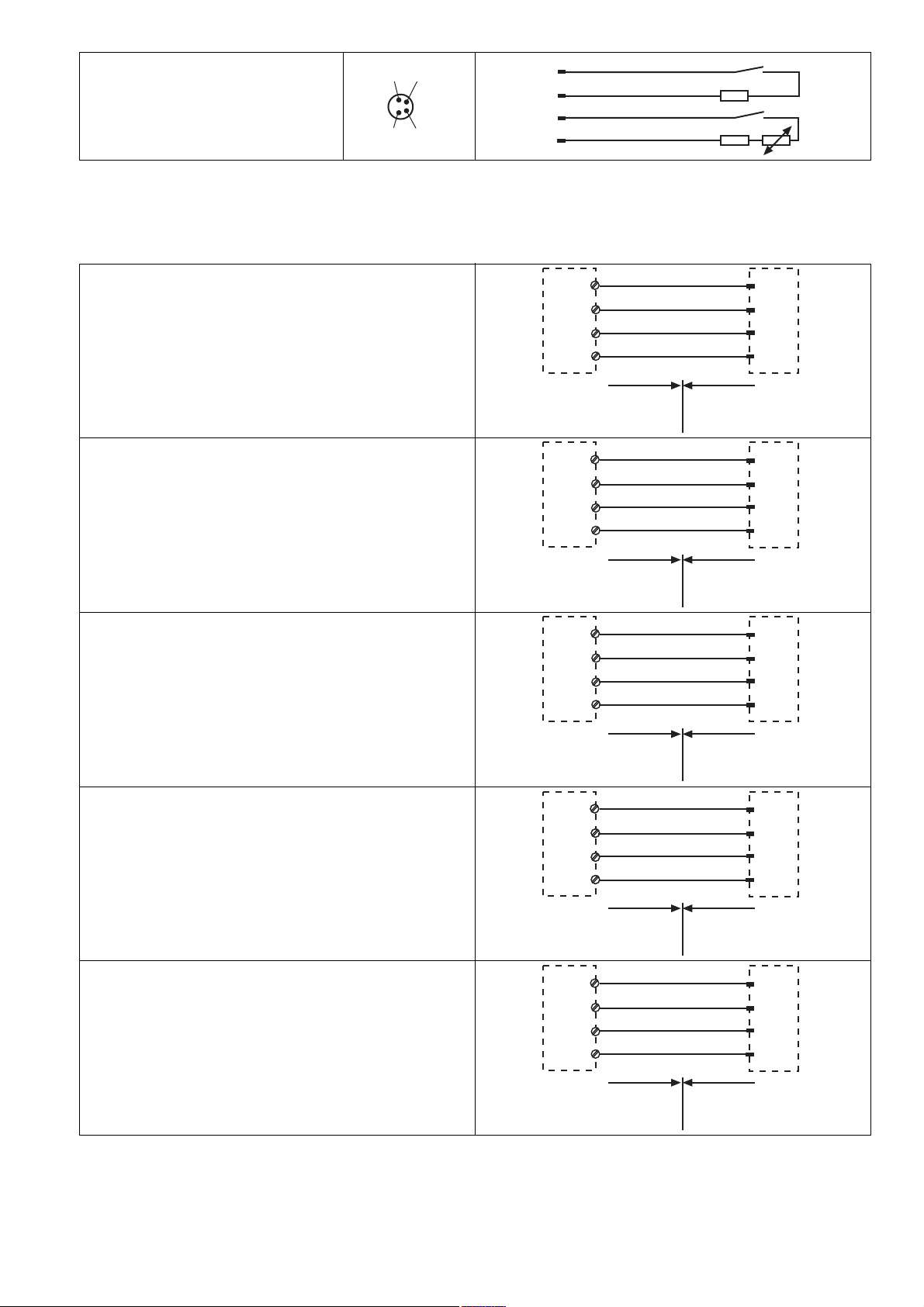
Belegung des 4-pol. M8-Stiftsteckers/Assign-
1
2
3
4
weiß/white/blanc
braun/brown/marron
blau/blue/bleu
schwarz/black/noir
1
2
3
4
PNOZ p1p
PNOZ p1vp
PNOZ X2/X2P
PNOZ X2.1
(nur 24 V DC/
24 V DC only/
24 V DC seulement)
PNOZ X2.3P
PNOZ X2.7P
PNOZ X2.8P
PNOZ X2C
PNOZ X2.1C
(nur 24 V DC/
24 V DC only/
24 V DC seulement)
PNOZ X4/X8P
PNOZ X9
PNOZ X10/X10.1
PNOZ X10.11
PNOZ Ex
PNOZ e1p
PNOZ e1.1p
PNOZ e1vp
PNOZ e6.1p
PNOZ e6vp
PNOZ s3
PNOZ s4
PNOZ s5
S21
S22
S11
S12
blau/blue/bleu
weiß/white/blanc
braun/brown/marron
schwarz/black/noir
1
2
3
4
Nicht-Ex-Bereich/Non-Ex
area/Zone Non Ex
Ex-Bereich/Ex area/
Zone Ex
PNOZ X2.9P
S11
S52
S11
S12
blau/blue/bleu
weiß/white/blanc
braun/brown/marron
schwarz/black/noir
1
2
3
4
Nicht-Ex-Bereich/Non-Ex
area/Zone Non Ex
Ex-Bereich/Ex area/
Zone Ex
PNOZ X5
PNOZ X5J
S11
S22
S11
S12
blau/blue/bleu
weiß/white/blanc
braun/brown/marron
schwarz/black/noir
1
2
3
4
Nicht-Ex-Bereich/Non-Ex
area/Zone Non Ex
Ex-Bereich/Ex area/
Zone Ex
PNOZ 11
PNOZ 16
PNOZ X11P
PNOZ X13
PNOZ X3.1
PNOZ X3P
PNOZ X2.5P
PNOZ X3
PNOZ X3.10P
PNOZ XV2
PNOZ XV2P
PNOZ XV3
PNOZ XV3P
S21
S22
S31
S32
blau/blue/bleu
weiß/white/blanc
braun/brown/marron
schwarz/black/noir
1
2
3
4
S21
S22
S31
S32
blau/blue/bleu
weiß/white/blanc
braun/brown/marron
schwarz/black/noir
1
2
3
4
Nicht-Ex-Bereich/Non-Ex
area/Zone Non Ex
Ex-Bereich/Ex area/
Zone Ex
PNOZ X6 (mit Brücke/with link/avec pontage Y3-Y4)PNOZ X6 (mit Brücke/with link/avec pontage Y3-Y4)
S23
S24
S11
S12
blau/blue/bleu
weiß/white/blanc
braun/brown/marron
schwarz/black/noir
1
2
3
4
Nicht-Ex-Bereich/Non-Ex
area/Zone Non Ex
Ex-Bereich/Ex area/
Zone Ex
ment of the 4-pin M8 male connector/Repérage du connecteur mâle M8 à 4 pôles
Anschluss an Auswertegeräte Connection to evaluation devices Raccordement aux unités de contrôle
Anschluss an PNOZ X, PNOZpower, PNOZ-
sigma, PNOZelog
Connection to PNOZ X, PNOZpower,
PNOZsigma, PNOZelog
Raccordement au PNOZ X, PNOZpower,
PNOZsigma, PNOZelog
- 3 -
Page 4

Anschluss an PNOZmulti Connection to PNOZmulti Raccordement au PNOZmulti
PMUT X1P
S61
S62
S51
S52
blau/blue/bleu
weiß/white/blanc
braun/brown/marron
schwarz/black/noir
1
2
3
4
Nicht-Ex-Bereich/Non-Ex
area/Zone Non Ex
Ex-Bereich/Ex area/
Zone Ex
PNOZ e5.11p
A1
S22
A1
S12
blau/blue/bleu
weiß/white/blanc
braun/brown/marron
schwarz/black/noir
1
2
3
4
Nicht-Ex-Bereich/Non-Ex
area/Zone Non Ex
Ex-Bereich/Ex area/
Zone Ex
A1
S42
A1
S32
blau/blue/bleu
weiß/white/blanc
braun/brown/marron
schwarz/black/noir
1
2
3
4
Nicht-Ex-Bereich/Non-Ex
area/Zone Non Ex
Ex-Bereich/Ex area/
Zone Ex
Schutztür/safety gate/protecteur mobile
Schaltertyp 3/switch type 3/type du capteur 3
I0, I1: Eingänge/inputs/entrées
T0, T1: Testtaktausgänge/test pulse outputs/sorties
impulsionelles
T0
T1
I0
I1
1
2
3
4
blau/blue/
bleu
weiß/white/blanc
braun/brown/marron
schwarz/black/noir
Nicht-Ex-Bereich/Non-Ex
area/Zone Non Ex
Ex-Bereich/Ex area/
Zone Ex
Schutztür/safety gate/protecteur mobile
Schaltertyp 3/switch type 3/type du capteur 3
I0, I1: Eingänge/inputs/entrées
O16, O17: Testtaktausgänge/test pulse outputs/sorties
impulsionelles
blau/blue/bleu
weiß/white/blanc
braun/brown/marron
schwarz/black/noir
O16
O17
I0
I1
1
2
3
4
Nicht-Ex-Bereich/Non-Ex
area/Zone Non Ex
Ex-Bereich/Ex area/
Zone Ex
Anschluss an PSS mit oder ohne SafetyBUS p Connection to PSS with or without Safety-
BUS p
Raccordement au PSS avec ou sans
SafetyBUS p
- 4 -
Page 5

Montage
26
19
22
36
10,6
M8x1
8,5
4,5
6,8
13
6,5
19
22
36
8,5
4,5
13
26
Safety switch
Actuator
516039435
Die Montagelage ist beliebig. Sicherheits-
schalter und Betätiger müssen jedoch parallel gegenüberliegend montiert werden.
Sicherheitsschalter und Betätiger möglichst
nicht auf ferromagnetisches Material montieren. Es sind Änderungen der Schaltabstände
zu erwarten. Benutzen Sie in diesem Fall die
Distanzplatte mit der Bestell-Nr. 534 310.
Befestigen Sie Sicherheitsschalter und Betä-
tiger ausschließlich mit Schrauben M4 mit
flacher Kopfunterseite (z.B. M4-Zylinderkopf- oder -Flachkopfschrauben). Anzugsdrehmoment max. 1 Nm. Verwenden Sie
Schrauben aus nicht magnetischem Material
(z. B. Messing).
Der Abstand zwischen zwei Systemen aus
Sicherheitsschalter und Betätiger muss mindestens 25 mm betragen.
Sicherheitsschalter und Betätiger
– von Eisenspänen fernhalten
– keinen starken Magnetfeldern aussetzen
– keinen starken Stößen oder Schwingun-
gen aussetzen
– nicht als Anschlag benutzen
876416011
Die Schutzart IP67 wird nur bei Verwendung
der als Zubehör erhältlichen Anschlussleitungen von Pilz erreicht. Ansonsten wird nur
IP65 erreicht.
Justage
516041739
Der Sicherheitsschalter darf nur mit dem zu-
gehörigen Betätiger PSEN 1.1-20 verwendet
werden.
Prüfen Sie die Funktion immer mit einem der
zugelassenen Auswertegeräte.
Die angegebenen Schaltabstände (siehe
technische Daten) gelten nur, wenn Sicherheitsschalter und Betätiger parallel gegenüberliegend montiert sind. Andere
Anordnungen können zu abweichenden
Schaltabständen führen. Beachten Sie den
maximal zulässigen Seiten- und Höhenversatz (siehe "Schaltabstände" und "Max. Seiten- und Höhenversatz").
Installation
The unit can be installed in any position.
However, safety switches and actuators
must be positioned opposite each other in
parallel:
If possible, do not install the safety switch
and actuator on to ferromagnetic material.
Changes to the operating distances are to be
expected. In this case, use the spacer available under order number 534 310.
Safety switches and actuators should only
be secured using M4 screws with a flat head
(e.g. M4 cheese-head or pan head screws).
Torque setting max. 1 Nm. Use screws made
of non-magnetic material (e.g. Messing).
The distance between two systems compris-
ing safety switch and actuator must be at
least 25 mm.
Safety switch and actuator
– Keep away from iron swarf
– Do not expose to strong magnetic fields
– Do not expose to heavy shock or vibration
– Do not use as a limit stop
Protection type IP67 can only be achieved by
using the Pilz connection leads available as
an accessory. In any other case only IP65 is
achieved.
Adjustment
The safety switch may only be used with the
corresponding actuator PSEN 1.1-20.
Always test the function with one of the ap-
proved evaluation devices.
The stated operating distances (see Techni-
cal details) only apply when the safety switch
and actuator are installed facing each other
in parallel. Switching distances may deviate
if other arrangements are used. Note the
maximum permitted lateral and vertical offset (see "Operating distances" and "Max. lateral and vertical offset").
Installation
Le sens de montage est indifférent. Cepen-
dant, le capteur de sécurité et l'actionneur
doivent être montés l'un en face de l'autre de
manière parallèle.
Evitez d'installer le capteur de sécurité et
l'actionneur sur du matériel ferromagnétique.
Les distances de commutation peuvent être
modifiées. Dans ce cas, utilisez la plaque
d'écartement portant la référence 534 310.
Pour fixer le capteur de sécurité et l'action-
neur, utilisez uniquement des vis M4 dont la
tête présente une face inférieure plate (par
ex. vis M4 cylindriques ou à tête plate). Couple de serrage max. 1 Nm. Utilisez des vis
dans des matériaux non magnétiques (par
exemple : en laiton).
La distance entre deux systèmes composés
d'un capteur de sécurité et d'un actionneur
doit être d'au moins 25 mm.
Le capteur de sécurité et l'actionneur
– doivent être éloignés des copeaux métalli-
ques
– ne doivent pas être exposés à des champs
magnétiques élevés
– ne doivent pas subir des chocs et vibra-
tions importants
– ne doivent pas être utilisés comme butée
L'indice de protection IP67 est uniquement
atteint lorsque les câbles de raccordement
de Pilz, disponibles dans les accessoires,
sont utilisés, sans quoi, seul l'indice IP65
peut être atteint.
Ajustement
Le capteur de sécurité ne doit être utilisé
qu'avec un organe de commande PSEN 1.120 adapté.
Vérifiez la fonction toujours avec l'un des ap-
pareils de contrôle homologués.
Les distances de commutation mentionnées
dans les caractéristiques techniques sont
valables uniquement lorsque le capteur de
sécurité et l'organe de commande sont montés l'un en face de l'autre de manière parallèle. D'autres montages peuvent conduire à
des distances de commutation divergentes.
Respectez le décalage latéral et vertical
maximal autorisé (voir "Distances de commutation" et "Décalage latéral et vertical
maximum").
Abmessungen Dimensions Dimensions
- 5 -
Page 6

Technische Daten Technical details Caractéristiques techniques
Elektrische Daten Electrical data Données électriques
Schaltspannung Switching voltage Tension de commutation 24 V
Innenwiderstand Internal resistance Résistance interne 10 Ohm
Max. Schaltstrom Sicherheitskon-
takte
Max. Schaltleistung Sicherheits-
kontakte
Max. switching current for safety
contacts
Max. breaking capacity for safety
contacts
Courant max. de commutation des
contacts de sécurité
Puissance max. de commutation
des contacts de sécurité
0,50 A
10,0 W
Max. Schaltfrequenz Max. switch frequency Fréquence de commutation max. 1 Hz
Umweltdaten Environmental data Données sur l'environnement
ATEX Kategorie Gas ATEX Category Gas ATEX catégorie gaz II 3G Ex nCc IIC T6 X
ATEX Kategorie Staub ATEX Category Dust ATEX catégorie poussière II 3D Ex tc IIIC T80°C X IP67
Einsatzbereich Application area Champ d'application X: -10°C ≤ ta ≤ +55°C
Umgebungstemperatur Ambient temperature Température d'utilisation -10 - 55 °C
Schwingungen nach EN 60947-5-2 Vibration to EN 60947-5-2 Vibrations selon EN 60947-5-2
Frequenz Frequency Fréquence 10 - 55 Hz
Amplitude Amplitude Amplitude 1,00 mm
EMV EMC CEM EN 60947-5-3
Schockbeanspruchung Shock stress Résistance aux chocs 30g , 11 ms
Verschmutzungsgrad Pollution degree Niveau d'encrassement 3
Bemessungsisolationsspannung Rated insulation voltage Tension assignée d'isolement 25 V
Bemessungsstoßspannungsfestig-
keit
Rated impulse withstand voltage Tension assignée de tenue aux
chocs
0,33 kV
Mechanische Daten Mechanical data Caractéristiques mécaniques
Betätiger Actuator Actionneur PSEN 1.1-20
Hysterese typ. Hysteresis typ. Hystérésis env. 5,0 mm
Schaltabstände Switching distances Distances de commutation
Gesicherter Schaltabstand S
Min. Schaltabstand S
omin
Gesicherter Ausschaltabstand S
Anschlussart Connection type Type de connection M8
Leitung Cable Câble LiYY 4 x 0,25 mm
Assured operating distance S
ao
Min. operating distance S
Assured release distance S
ar
omin
ar
Distance de commutation de sécu-
ao
rité S
ao
Distance de commutation min.
S
omin
Distance de déclenchement de sécurité S
ar
8,0 mm
0,5 mm
26,0 mm
2
Schutzart Gehäuse Protection type, housing Indice de protection du boîtier IP65, IP67
Gehäusematerial Housing material Matériau du boîtier PC
Abmessungen siehe Abbildung Dimensions, see graphic Dimensions, voir l'illustration
Gewicht Weight Poids
Sicherheitsschalter Safety switch Capteur de sécurité 14 g
Betätiger Actuator Actionneur 17 g
Sicherheitstechnische Kenndaten
B10d nach EN ISO 13849-1 und EN
IEC 62061
Lambda
62061
/Lambda nach EN IEC
d
Safety-related characteristic
data
B10d in accordance with EN ISO
13849-1 and EN IEC 62061
Lambdad/Lambda in accordance
with EN IEC 62061
Caractéristiques techniques de
sécurité
B10d selon l'EN ISO 13849-1 et
l'EN CEI 62061
Lambdad/Lambda selon l'EN CEI
62061
500.000
0,90
- 6 -
Page 7

Es gelten die 2006-12 aktuellen Ausgaben der
Normen.
1128680331
INFO
Bestellnummern und Zubehör finden Sie im
Technischen Katalog oder auf unserer Internetseite www.pilz.com.
EG-Konformitätserklärung
1139424011
Diese(s) Produkt(e) erfüllen die Anforderungen
der Richtlinie 2006/42/EG über Maschinen des
europäischen Parlaments und des Rates. Die
vollständige EG-Konformitätserklärung finden
Sie im Internet unter www.pilz.com.
Bevollmächtigter: Norbert Fröhlich, Pilz GmbH
& Co. KG, Felix-Wankel-Str. 2, 73760 Ostfildern, Deutschland
21 098-3FR-082011-11Printed in Germany
The standards current on 2006-12 apply. Les versions actuelles 2006-12 des normes
s'appliquent.
INFORMATION
Order numbers and accessories can be
found in the Technical Catalogue or on our
Internet site www.pilz.com.
EC Declaration of Conformity
This (these) product(s) comply with the requirements of Directive 2006/42/EC of the European
Parliament and of the Council on machinery.
The complete EC Declaration of Conformity is
available on the Internet at www.pilz.com.
Authorised representative: Norbert Fröhlich,
Pilz GmbH & Co. KG, Felix-Wankel-Str. 2,
73760 Ostfildern, Germany
INFORMATION
Vous trouverez les références et les accessoires dans le catalogue technique ou sur
notre site www.pilz.com.
Déclaration de conformité CE
Ce(s) produit(s) satisfait (satisfont) aux exigences de la directive 2006/42/CE relative aux machines du Parlement Européen et du Conseil.
Vous trouverez la déclaration de conformité CE
complète sur notre site internet www.pilz.com.
Représentant : Norbert Fröhlich, Pilz GmbH &
Co. KG, Felix-Wankel-Str. 2, 73760 Ostfildern,
Allemagne
Originalbetriebsanleitung/Original instructions/Notice originale
21 098-3FR-08, 2011-11 Printed in Germany Printed in Germany
 Loading...