

Page 1
Two-hand control unit
Up to PL e of EN ISO 13849-1
P2HZ X1P
Gertebild
][Bildunterschrift_Zweihand
Two-hand control unit for press controllers and safety circuits
Approvals
P2HZ X1P
Zulassungen
Unit features
Gertemerkmale
` Positive-guided relay outputs:
– 3 safety contacts (N/O), instanta-
neous
– 1 auxiliary contact (N/C), instan-
taneous
` 2 semiconductor outputs
` Connection options for:
– 2 operator elements (buttons)
` LED indicator for:
– Switch status channel 1/2
– Supply voltage
` Semiconductor outputs signal:
– Switch status channel 1/2
– Supply voltage is present
` Plug-in connection terminals (either
spring-loaded terminal or screw
terminal)
` See order reference for unit types
Unit Description
][Gertebeschreibung_Zweihand
The two-hand control relay meets the
requirements of EN 574 Type IIIC. It
forces the operator to keep his hands
outside the danger zone area during
the hazardous movement. The unit is
suitable for use on controllers for metalworking presses as a component for
simultaneous switching.
It can be used in applications with
` Mechanical presses (EN 692)
` Hydraulic presses (EN 693)
` Safety circuits in accordance with
EN 60204-1
Safety features
][Sicherheitseigenschaften_Zweihand
The two-hand control relay meets the
following safety requirements:
` The circuit is redundant with built-in
self-monitoring
` The safety function remains effec-
tive in the case of a component failure
` The circuit prevents a further press
stroke in the case of:
– Relay failure
– Contact welding
– Coil defect on a relay
– Open circuit
– Short circuit
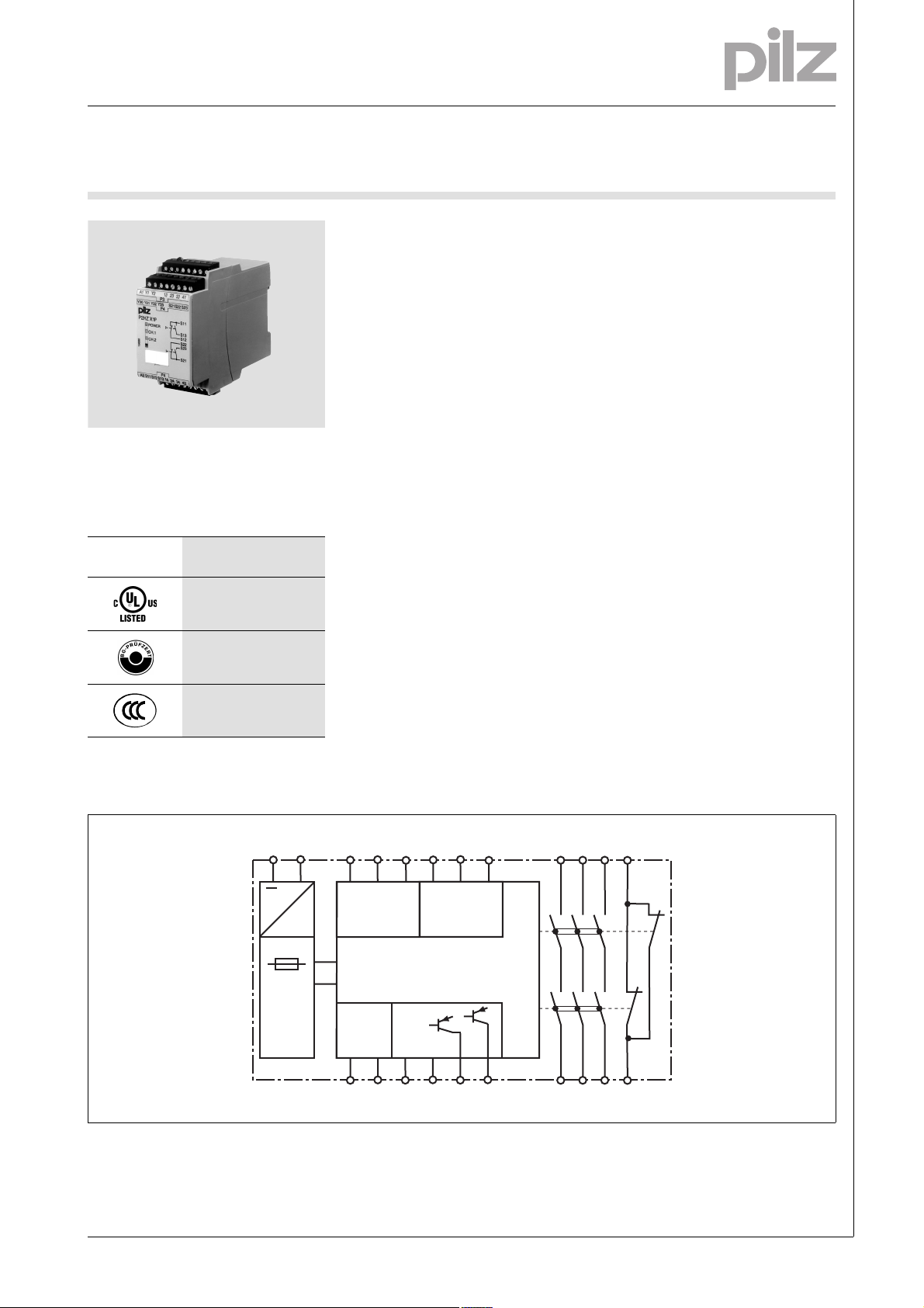
Block diagram
Blockschaltbild
A1 A2 S21 S22 S23
S11 S12 S13
~
Input
Power
=
Input
Feed-
back
Y1 Y2
0 V 24 V
Y30 Y31 Y32 Y35
13 23 33 41
K1
K2
14 24 34 42
NSG-D-2-163-2010-09
Page 2
Two-hand control unit
Up to PL e of EN ISO 13849-1
P2HZ X1P
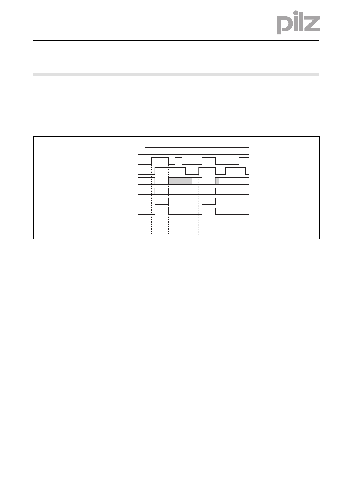
Function description
][Funktionen_Zweihand
` The two-hand control relay must be
activated by simultaneously pressing two buttons within 500 ms. If
Timing diagram
POWER
Button 1
Button 2
Feedback loop
Output safe
Output aux.
Out semi CH
Out semi RUN
Key
` POWER: Supply voltage
` Button 1/Button 2: Input circuits
S11-S12-S13, S21-S22-S23
` Feedback loop: Feedback loop Y1-
Y2
` Output safe: Safety outputs 13-14,
23-24, 33-34
one or both of the buttons are released, the unit interrupts the control command for the hazardous
movement.
][Zeitdiagram_Zweihand_aux_semiRUN_semiCH
t0 t1 t2 t3 t3 t1
t1
` Output aux: Auxiliary contacts 41-
42
` Out semi RUN: Semiconductor out-
put for operational readiness Y35
` Out semi CH: Semiconductor out-
put switch status Y32
: Recovery time after power on
` t
0
` Reactivation: The output relays will
not re-energise until both operator
elements have been released and
then re-operated simultaneously.
: Simultaneity, channel 1 and 2
` t
1
: Operating cycle ended through
` t
2
button 1 or 2
: Y1-Y2 must be closed before
` t
3
before the button is operated (recovery time)
Shaded area: Status irrelevant
Wiring
][Verdrahtung_Si_unverz_1Hi_unverz
Please note:
` Information given in the “Technical
details” must be followed.
` Outputs 13-14, 23-24, 33-34 are
safety contacts, output 41-42 is an
auxiliary contact (e.g. for display).
` To prevent contact welding, a fuse
should be connected before the
output contacts (see technical details).
` Calculation of the max. cable runs
in the input circuit:
l
max
R
lmax
=
I
max
Rl / km
R
= max. overall cable resist-
lmax
ance (see technical details)
/km = cable resistance/km
R
l
` Use copper wire that can withstand
60/75 °C.
` Sufficient fuse protection must be
provided on all output contacts with
capacitive and inductive loads.
NSG-D-2-163-2010-09
-2
Page 3
Two-hand control unit
Up to PL e of EN ISO 13849-1
P2HZ X1P
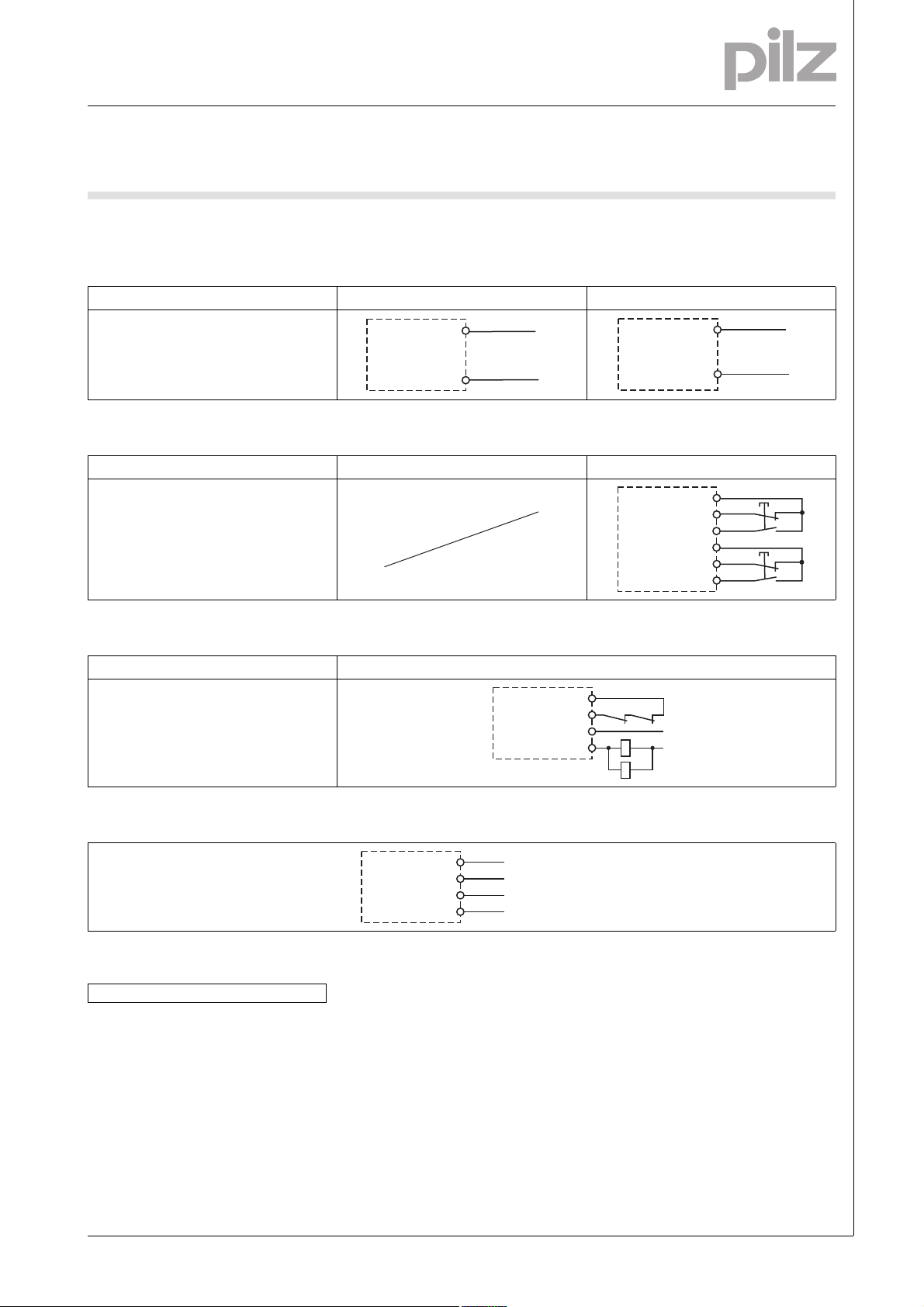
Preparing for operation
Betriebsbereitschaft her stellen
` Supply voltage
Supply voltage AC DC
A1
A2
L1
N
` Input circuit
Input circuit Single-channel Dual-channel
Two-hand button
with detection of shorts across contacts
` Feedback loop
Feedback loop
Contacts from external contactors
Y1
Y2
13 (23, 33)
14 (24, 34)
K5
K6
K5
K6
L1
N
A1
A2
S11
S12
S13
S21
S22
S23
L+
L-
S1
S2
` Semiconductor output
` Key
S1/S2 Two-hand button
Y31
Y32
Y35
Y30
24 V DC
SPS Input
SPS Input
0 V
NSG-D-2-163-2010-09
Page 4

Two-hand control unit
Up to PL e of EN ISO 13849-1
P2HZ X1P
Terminal configuration
Y30
19880
Y1 Y24213A1
Y31
P2HZ X1P
POWER
CH.1
CH.2
Y32
Klemmenbelegung
Y35
P3
P4
23
S21
33
S22
41
S23
S11
S13
S12
S22
S23
S21
Installation
][Montage_Zweihand
` The safety relay should be installed
in a control cabinet with a protection type of at least IP54.
` Use the notch on the rear of the unit
to attach it to a DIN rail.
` Ensure the unit is mounted securely
on a vertical DIN rail (35 mm) by using a fixing element (e.g. retaining
bracket or an end angle).
Notice
The distance of the button connected
to the two-hand relay from the nearest
danger zone must be large enough
that if one of the buttons is released,
the dangerous moment is interrupted
before the operator can reach into the
danger zone (see EN 999 “The positioning of protective equipment in respect of approach speeds of parts of
the human body”).
A2
Dimensions
Abmessungen
* with spring-loaded terminals
94 (3.70")
* 101 (3.98")
S11 S12
S13
P4
14
24
121 (4.76")
34
45
(1.77")
NSG-D-2-163-2010-09
-4
Page 5

Two-hand control unit
Up to PL e of EN ISO 13849-1
P2HZ X1P
Notice
][Wichtig_PDB
This data sheet is only intended for use
during configuration. Please refer to
the operating manual for installation
and operation.
Service life graph
Lebensdauerkurve_Rela is_Text vor Kurv e
The service life graphs indicate the
number of cycles from which failures
due to wear must be expected. The
wear is mainly caused by the electrical
load; the mechanical load is negligible.
Lebensdauerkurve_Relai s_Text nach Kurv e_SIS212_SIR-SLR B sp
Example
` Inductive load: 0.2 A
` Utilisation category: AC15
` Contact service life: 1 000 000 cy-
cles
Provided the application requires fewer than 1 000 000 cycles, the PFH val-
10
AC15: 230 V
DC13: 24 V
1
Courant coupé (A)
D Nennbetriebstrom (A)
GB Nominal operating current (A)
0.1
F
E Corriente nominal de servicio (A)
I Corrente di esercizio nominale (A)
NL Nominale bedrijfsstroom (A)
D Schaltspielzahl x 10
GB Cycles x 10
F Nombre de manuvres x 10
10 100 1000 10000
3
3
ue (see technical details) can be used
in the calculation.
To increase the service life, sufficient
spark suppression must be provided
on all output contacts. With capacitive
loads, any power surges that occur
must be noted. With contactors, use
Lebensdauerkurve
DC1: 24 V
AC1: 230 V
E Número de ciclos x 10
I Numero dei cicli di commutazione x 10
3
NL Aantal schakelingen x 10
3
3
freewheel diodes for spark suppression.
Lebensdauerkurve_Relais_Text nach Kurve-2_ Empfehlung Halbleiterausgänge
We recommend you use semiconductor outputs to switch 24 VDC loads.
][Technische Daten Zweih and
3
Technical details
Electrical data
Supply voltage
Supply voltage U
Supply voltage U
AC 24 V, 42 V, 48 V, 110 V, 115 V, 120 V, 230 V, 240 V
B
DC 24 V
B
Voltage tolerance -15 %/+10 %
Power consumption at U
AC 6.0 VA No. 777330, 777331, 777332, 777434, 777435, 777436,
B
777438, 777439, 787330, 787331, 787332, 787434, 787435,
787436, 787438, 787439
Power consumption at U
DC 2.5 W No. 777340, 787340
B
Frequency range AC 50 - 60 Hz
Residual ripple DC 10 %
Voltage and current atn
Input circuit DC: 24.0 V
N/O contact 30 mA
N/C contact 20 mA
Feedback loop DC: 24.0 V 45.0 mA
Number of output contacts
Safety contacts (S) instantaneous: 3
Auxiliary contacts (N/C): 1
NSG-D-2-163-2010-09
Page 6

Two-hand control unit
Up to PL e of EN ISO 13849-1
P2HZ X1P
Electrical data
Utilisation category in accordance with EN 60947-4-1
Safety contacts: AC1 at 240 V I
Safety contacts: DC1 at 24 V I
Auxiliary contacts: AC1 at 240 V I
Auxiliary contacts: DC1 at 24 V I
: 0.01 A , I
min
P
: 1250 VA
max
: 0.01 A , I
min
: 125 W
P
max
: 0.01 A , I
min
: 500 VA
P
max
: 0.01 A , I
min
P
: 50 W
max
Utilisation category in accordance with EN 60947-5-1
Safety contacts: AC15 at 230 V I
Safety contacts: DC13 at 24 V (6 cycles/min) I
Auxiliary contacts: AC15 at 230 V I
Auxiliary contacts: DC13 at 24 V (6 cycles/min) I
max
max
max
max
: 2.5 A
: 1.5 A
: 2.0 A
: 1.5 A
Conventional thermal current 5.0 A
Contact material AgSnO2 + 0.2 µm Au
External contact fuse protection (I
= 1 kA) to EN 60947-5-1
K
Blow-out fuse, quick
Safety contacts: 6 A
Auxiliary contacts: 4 A
Blow-out fuse, slow
Safety contacts: 4 A
Auxiliary contacts: 2 A
Circuit breaker 24 VAC/DC, characteristic B/C
Safety contacts: 4 A
Auxiliary contacts: 2 A
Semiconductor outputs (short circuit proof) 24.0 V DC, 20 mA
External supply voltage 24.0 V DC
Voltage tolerance -15% / +10%
Max. overall cable resistance R
per input circuit 14 Ohm
lmax
Safety-related characteristic data
PL in accordance with EN ISO 13849-1 PL e (Cat. 4)
Category in accordance with EN 954-1 Cat. 4
SIL CL in accordance with EN IEC 62061 SIL CL 3
PFH in accordance with EN IEC 62061 3.01E-09
SIL in accordance with IEC 61511 SIL 3
PFD in accordance with IEC 61511 3.24E-06
t
in years 20
M
Times
Delay-on de-energisation (reaction time in accordance with
EN 574)
N/O contact 15 ms
N/C contact 30 ms
Recovery time 250 ms
Simultaneity, channel 1 and 2 500 ms
Environmental data
EMC EN 60947-5-1, EN 61000-6-2
Vibration to EN 60068-2-6
Frequency 10 - 55 Hz
Amplitude 0.35 mm
Climatic suitability EN 60068-2-78
Airgap creepage in accordance with EN 60947-1
Pollution degree 2
Overvoltage category III
Rated insulation voltage 250 V
Rated impulse withstand voltage 4.00 kV
Ambient temperature -25 - 55 °C
max
max
max
max
: 5.0 A
: 5.0 A
: 2.0 A
: 2.0 A
NSG-D-2-163-2010-09
-6
Page 7

Two-hand control unit
Up to PL e of EN ISO 13849-1
P2HZ X1P
Environmental data
Storage temperature -40 - 85 °C
Protection type
Mounting (e.g. cabinet) IP54
Housing IP40
Terminals IP20
Mechanical data
Housing material
Housing PPO UL 94 V0
Front ABS UL 94 V0
Cross section of external conductors with screw terminals
1 core flexible 0.25 - 2.50 mm² , 24 - 12 AWG No. 777330, 777331, 777332,
777340, 777434, 777435, 777436, 777438, 777439
2 core, same cross section, flexible:
with crimp connectors, without insulating sleeve 0.25 - 1.00 mm² , 24 - 16 AWG No. 777330, 777331, 777332,
without crimp connectors or with TWIN crimp connectors 0.20 - 1.50 mm² , 24 - 16 AWG No. 777330, 777331, 777332,
Torque setting with screw terminals 0.50 Nm No. 777330, 777331, 777332, 777340, 777434, 777435,
Cross section of external conductors with spring-loaded terminals: Flexible with/without crimp connectors
Spring-loaded terminals: Terminal points per connection 2 No. 787330, 787331, 787332, 787340, 787434, 787435, 787436,
Stripping length 8 mm No. 787330, 787331, 787332, 787340, 787434, 787435,
Dimensions
Height 101.0 mm No. 787330, 787331, 787332, 787340, 787434,
Width 45.0 mm
Depth 121.0 mm
Weight 240 g No. 787340
Technische Daten_Satz No .
No. stands for order number.
777340, 777434, 777435, 777436, 777438, 777439
777340, 777434, 777435, 777436, 777438, 777439
777436, 777438, 777439
0.20 - 1.50 mm² , 24 - 16 AWG No. 787330, 787331, 787332,
787340, 787434, 787435, 787436, 787438, 787439
787438, 787439
787436, 787438, 787439
787435, 787436, 787438, 787439
94.0 mm No. 777330, 777331, 777332, 777340, 777434, 777435,
777436, 777438, 777439
250 g No. 777340
350 g No. 787330, 787331, 787332, 787434, 787435, 787436,
787438, 787439
360 g No. 777330, 777331, 777332, 777434, 777435, 777436,
777438, 777439
Si-Kennzahlen_Zusatz_Relais_Lebensdauer_PDB
It is essential to consider the relay's
service life graphs. The relay outputs'
safety-related characteristic data is
only valid if the values in the service life
graphs are met.
All the units used within a safety function must be considered when calculating the safety characteristic data.
Technische Daten_Satz No rmen
The standards current on 2010-07 apply.
Bestelldaten
The PFH value depends on the switching frequency and the load on the relay
output. If the service life graphs are not
accessible, the stated PFH value can
be used irrespective of the switching
frequency and the load, as the PFH
value already considers the relay's
B10d value as well as the failure rates
of the other components.
Si_Kennzahlen_Erläute rung
NSG-D-2-163-2010-09
Page 8

Two-hand control unit
Up to PL e of EN ISO 13849-1
P2HZ X1P
Order reference
Type Features Terminals Order no.
P2HZ X1P C 24 VAC Spring-loaded terminals 787 330
P2HZ X1P 24 VAC Screw terminals 777 330
P2HZ X1P C 42 VAC Spring-loaded terminals 787 331
P2HZ X1P 42 VAC Screw terminals 777 331
P2HZ X1P C 48 VAC Spring-loaded terminals 787 332
P2HZ X1P 48 VAC Screw terminals 777 332
P2HZ X1P C 110 VAC Spring-loaded terminals 787 434
P2HZ X1P 110 VAC Screw terminals 777 434
P2HZ X1P C 115 VAC Spring-loaded terminals 787 435
P2HZ X1P 115 VAC Screw terminals 777 435
P2HZ X1P C 120 VAC Spring-loaded terminals 787 436
P2HZ X1P 120 VAC Screw terminals 777 436
P2HZ X1P C 230 VAC Spring-loaded terminals 787 438
P2HZ X1P 230 VAC Screw terminals 777 438
P2HZ X1P C 240 VAC Spring-loaded terminals 787 439
P2HZ X1P 240 VAC Screw terminals 777 439
P2HZ X1P C 24 VDC Spring-loaded terminals 787 340
P2HZ X1P 24 VDC Screw terminals 777 340
NSG-D-2-163-2010-09
-8
 Loading...