

Page 1

20124-6NL-05
P2HZ X1
4
D Betriebsanleitung
4
GB Operating instructions
4
F Manuel d'utilisation
4 E Instrucciones de uso
4 I Istruzioni per l'uso
4 NL Gebruiksaanwijzing
Sicherheitsbestimmungen
• Das Gerät darf nur von Personen installiert
und in Betrieb genommen werden, die mit
dieser Betriebsanleitung und den geltenden Vorschriften über Arbeitssicherheit
und Unfallverhütung vertraut sind. Beachten Sie die VDE- sowie die örtlichen
Vorschriften, insbesondere hinsichtlich der
Schutzmaßnahmen.
• Beim Transport, bei der Lagerung und im
Betrieb die Bedingungen nach EN 60068-26 einhalten (s. technische Daten).
• Durch Öffnen des Gehäuses oder eigenmächtige Umbauten erlischt die Gewährleistung.
• Montieren Sie das Gerät in einen Schaltschrank; Staub und Feuchtigkeit können
sonst zu Beeinträchtigungen der Funktionen führen.
• Sorgen Sie an allen Ausgangskontakten
bei kapazitiven und induktiven Lasten für
eine ausreichende Schutzbeschaltung.
• Die Zweihandschaltung und die vor- und
nachgeschalteten Teile der Pressensteuerung müssen den einschlägigen VDEBestimmungen und den Sicherheitsregeln
EN 574; EN 692 und EN 693 entsprechen.
• Die Betriebsspannung des Zweihandbedienungsrelais darf nur nach der Ausschalteinrichtung gemäß § 9 VBG 7n5.1/2
angeschlossen werden.
• Verlegen Sie die Verbindungskabel zw.
P2HZ X1 und den Tastern nicht unmittelbar
neben Starkstromleitungen; es können
sonst induktive und kapazitive Störeinkopplungen entstehen.
• Verwenden Sie wegen der geringen
Ströme Tasterkontakte mit Goldauflage.
• Das Gerät darf nur wie in den Anschlussbeispielen im Kapitel "Anwendungen"
angeschlossen werden.
Safety Regulations
• The unit may only be installed and
operated by personnel who are familiar
with both these instructions and the
current regulations for safety at work and
accident prevention. Follow local
regulations especially as regards
preventative measures.
• Transport, storage and operating
conditions should all conform to
EN 60068-2-6
• Any guarantee is void following opening of
the housing or unauthorised
modifications.
• The unit should be panel mounted,
otherwise dampness or dust could lead to
functional impairment.
• Adequate protection must be provided on
all output contacts with capacitive and
inductive loads.
• The two-hand circuit and the connected
parts of the press control must conform
to the relevant safety standard EN 574
EN 692 and EN 693.
• The operating voltage of the two-hand
relay may only be connected according
to § 9 VBG 7n5.1/2 (cut-out devices)
• To avoid indirective coupling and capacitance effects, the cables to the two push
buttons must be run separately to any
power cables.
• Pushbutton contacts should be gold
plated due to the low current output.
• The unit is only to be connected as
shown in the connection diagrams chapter "Application".
(s. technical data).
;
Conseils préliminaires
• La mise en oeuvre de l'appareil doit être
effectuée par une personne spécialisée en
installations électriques, en tenant compte
des prescriptions des différentes normes
applicables (NF, EN, VDE..), notamment
au niveau des risques encourus en cas
de défaillance de l'équipement électrique.
• Respecter les exigences de la norme
EN 60068-2-6
stockage et de l'utilisation de l'appareil.
• Toutes interventions sur le boîtier (ouverture du relais, échange ou modification de
composants, soudure etc..) faites par
l'utilisateur annule la garantie.
• Montez l'appareil dans une armoire
électrique à l'abri de l'humidité et de la
poussière.
• Assurez-vous du pouvoir de coupure des
contacts de sortie en cas de charges
inductives ou capacitives.
• L'utilisation de commandes bimanuelles
suppose que par ailleurs l'ensemble des
circuits de la machine réponde aux règles
de sécurité concernant les machines
dangereuses (EN 574; EN 692 et EN
693).
• Le branchement de la tension d'alimentation du P2HZ doit être conforme aux
prescriptions § 9 VBG 7n5.1/2
• Pour éviter des interférences inductives
ou capacitives,il est préférable de placer le
câble reliant le P2HZ X1 aux organes de
commande loin des câbles de puissance.
• Utilisez des boutons poussoirs avec des
contacts dorés en raison des faibles
intensités commutées.
• Respectez les schémas de câblage du
relais donnés dans le chapitre "Utilisation".
lors du transport, du
Bestimmungsgemäße Verwendung
P2HZ X1 erfüllt die Anforderung nach EN 574
Typ III C. Das Zweihandbedienungsrelais
zwingt den Bediener einer Presse zur
Vermeidung von Handverletzungen die
Hände während der gefahrbringenden
Schließbewegung außerhalb der Gefahrenstelle zu halten.
P2HZ X1 ist zum Einbau in Steuerungen für
Pressen der Metallbearbeitung als Baustein
der Gleichzeitigkeit geeignet.
Das Gerät kann als Handschutzeinrichtung
nach den technischen Regeln
• Exzenter- und verwandte Pressen (EN 692)
• hydraulische Pressen (EN 693)
• Spindelpressen (EN 692)
oder in
• Sicherheitsstromkreise nach EN 60204-1;
VDE 0113-1 eingesetzt werden.
Als nicht bestimmungsgemäß gilt insbesondere:
•
jegliche bauliche, technische oder elektrische Veränderung eines Produkts,
•
der Einsatz eines Produkts außerhalb der
Bereiche, die in der Produktdokumentation
beschrieben sind,
•
ein von den dokumentierten technischen
Daten abweichender Einsatz.
Typical Applications
P2HZ X1 fulfils the requirements to EN 574
Type III C. The two-hand relay can be used
to enable a machine operator to avoid hand
injury. As the hands are kept out of the
hazard area during dangerous machine
movement, P2HZ X1 is suitable for use for
metalworking presses.
The P2HZ X1 is suitable for use in
controlling with metal working presses for
simultaneous switching.
The unit can be used as a hand protection
device according to the Technical Safety
Requirements:
• 'Eccentric and related presses' (EN 692)
• 'Hydraulic presses' (EN 693)
• 'Fly presses' (EN 692)or in
• Safety circuit according to EN 60204-1;
VDE 0113-1
The following is deemed improper use in
particular:
•
Any component, technical oder electrical
modification to a product
•
Use of a product outside the areas
described in the product documentation
•
Any use that is not in accordance with the
documented technical details.
- 1 -
Domaines d'utilisation
P2HZ X1 répond aux exigences de la norme
EN 574 pour les relais de type III C. Les
commandes bimanuelles sont des dispositifs
qui obligent les opérateurs à avoir les deux
mains situées en dehors de la zone
dangereuse durant la phase dangereuse de
la machine.
Le relais P2HZ X1 est spécialement adapté
pour assurer la fonction de simultanéité
et est utilisable comme relais de comande
bimanuelle selon les directives techniques
pour:
• les presses excentriques et apparentées
(EN 692)
• les presses hydrauliques (EN 693)
• les presses linéaires (EN 692)
ou
• les circuits de sécurité d'après la norme
EN 60204-1; VDE 0113-1
Est en particulier considéré comme non
conforme :
•
toute modification structurelle, technique
ou électrique d'un produit
•
I'utilisation d'un produit dans des
applications autres que celles décrites
dans la documentation des produits
•
une utilisation autre que celle spécifiée
dans les caractéristiques techniques.
Page 2
Gerätebeschreibung
Das Zweihandbedienungsrelais ist in einem
P-97-Gehäuse untergebracht. Es stehen
verschiedene Varianten für den Betrieb mit
Wechselspannung und eine Variante für den
Betrieb mit Gleichspannung zur Verfügung.
Merkmale:
• Relaisausgänge:
3 Sicherheitskontakte (Schließer) und ein
Hilfskontakt (Öffner), zwangsgeführt
• Halbleiterausgänge melden Zustand der
Ausgangsrelais und der Versorgungsspannung
• Statusanzeige für Ausgangsrelais und
Versorgungsspannung
• Rückführkreis zur Überwachung externer
Schütze
Das Zweihandbedienungsrelais erfüllt folgende
Sicherheitsanforderungen:
• Schaltung ist redundant mit Selbstüberwachung aufgebaut
• Sicherheitseinrichtung bleibt auch bei Ausfall
eines Bauteils wirksam
• Die Schaltung verhindert einen weiteren
Pressenhub bei Relaisversagen, Verschweißen eines Kontaktes, Spulendefekt
eines Relais, Leiterbruch, Kurzschluss
Description
The Two-Hand Control Relay is enclosed in a
P-97 housing. There are different versions
available for AC operation and one for DC
operation.
Features:
• Relay outputs:
3 safety contacts (N/O) and one auxiliary
contact (N/C), positive guided.
• Semiconductor outputs show the status of
the output relay and the operating voltage
• Status indicators for output relay and
operating voltage
• Feedback Control Loop for monitoring of
external contactors/relays.
The relay complies with the following safety
requirements:
• The circuit is redundant with built-in selfmonitoring.
• The safety function remains effective in the
case of a component failure.
• The circuit prevents a further press
stroke in the case of relay failure, contact
welding, coil defect in a relay, cable break,
short circuit
Description de l'appareil
Inséré dans un boîtier P-97 , le relais de
commande bimanuelle P2HZ X1 est disponible en différentes versions pour les tensions
d’alimentation alternatives et une version en
alimentation continue (24 VDC).
Particularités :
• Contacts de sortie :
3 contacts à fermeture de sécurité et un
contact à ouverture d'info
• 2 sorties statiques pour indication présence
tension d'alimentation et état du relais
• LEDs de visualisation pour tension
d'alimentation et relais de sortie
• Boucle de retour pour la surveillance des
contacteurs externe
Le bloc logique P2HZ X1 présente les
caractéristiques suivantes :
• Conception redondante avec auto-contrôle
• Fonction de sécurité assurée même en cas
de défaillance d'un composant interne.
• La conception du bloc logique P2HZ
empèche un nouveau cycle de la presse
en cas de défaillance d'un relais interne,
collage d'un contact, défaillance de la
bobine d'un relais, coupure d'une piste de
circuit imprimé, court-circuit.
Funktionsbeschreibung
Das Zweihandbedienungsrelais muss durch
gleichzeitiges Betätigen von zwei Tastern
aktiviert werden. Es unterbricht bei Loslassen
eines oder beider Taster den Steuerbefehl
zum Schließen der Presse. Die Schließbewegung kann erst wieder eingeleitet
werden, nachdem beide Taster in ihre
Ausgangslage zurückgekehrt (losgelassen)
sind und erneut betätigt wurden.
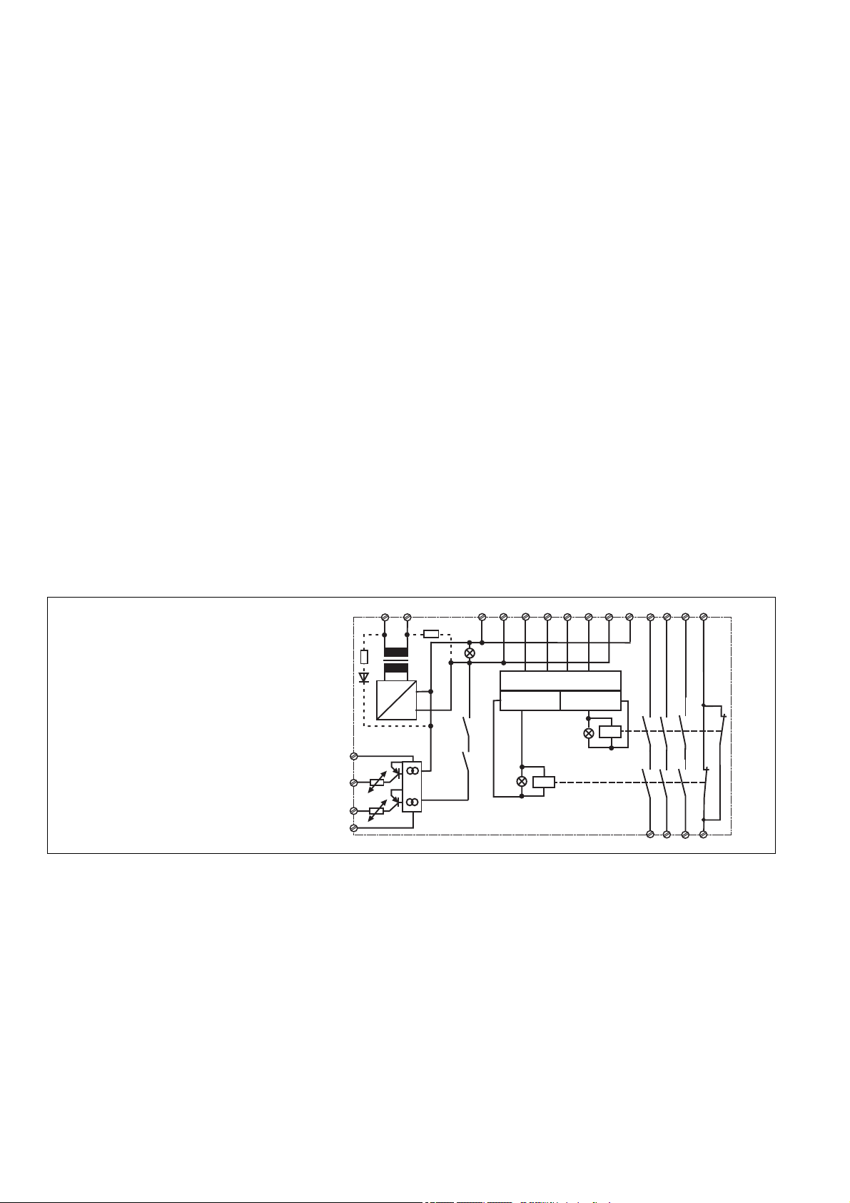
Fig. 1: Innenschaltbild /Connection
Diagram/Schéma de principe
Nach Anlegen der Versorgungsspannung U
und Schließen des Rückführkreises Y1-Y2 ist
das Gerät startbereit. Die LED "POWER"
leuchtet.
• Werden die beiden Taster "gleichzeitig",
d. h. innerhalb von 0,5 s betätigt, gehen
die beiden Ausgangsrelais K1 und K2 in
Arbeitsstellung und die Sicherheitskontakte
13-14/23-24/33-34 schließen, der Hilfskontakt 41-42 öffnet. Die LED "CH.1" und
"CH.2" leuchten.
• Die Ausgangsrelais ziehen nicht an, wenn
- nur ein Bedienelement betätigt wird
- die Gleichzeitigkeit überschritten wird
- der Rückführkreis noch offen ist
•
Wird nach gleichzeitigem Betätigen ein
Bedienelement losgelassen, fällt ein Ausgangsrelais wieder ab. Die zwangsgeführten
Sicherheitskontakte 13-14/23-24/33-34
öffnen und der Hilfskontakt 41-42 schließt.
Die LED "CH.1" bzw. "CH.2" ist aus.
Function Description
The two-hand control relay must be activated
by the simultaneous pressing of two buttons.
If one or both buttons are released, the
'enable' command of the equipment is
interrupted. The movement can then only be
initiated when both buttons have returned to
their original position (released) and pressed
again.
A2
A1
T1
+
~
=
K2
Y31
Y35
Y32
Y30
When the operating voltage UB is supplied
B
and the feedback control loop is closed,
then the unit is ready for operation. The
LED "POWER" illuminates.
• If buttons 1 and 2 are activated
'simultaneously' i.e. within 0.5 s, the output
relays K1 and K2 switch to operating
condition and the safety contacts 13-14/2324/33-34 close and the auxiliary contact
41-42 opens. The LED "CH.1"
and "CH.2" illuminate.
• The safety contacts do not energise if
- Only one button is pressed
- Simultaneity is not upheld
- The feedback control loop was not closed
• If one button is released following simultaneous activation, the output relay returns to
the original position. The positive-guided
safety contacts 13-14/23-24/33-34 open
and the auxiliary contact 41-42 closes. The
LED "CH.1" or "CH.2" is off.
K1
S12
S11
S13
Steuerlogik/Control logic/
Logique de commande
Kanal/Channel/
Canal 1
Description du fonctionnement
Le relais de commande bimanuelle est activé
par une action simultanée sur 2 boutons
poussoirs. Le relachement d'un des poussoirs entraîne immédiatement la retombée de
l'ordre de commande. Un nouvel ordre de
commande ne pourra alors être donné
qu'après un relachement des 2 poussoirs et
une nouvelle action simultanée sur ceux-ci.
S22
S21
S23
K2
Y2
Y1
Kanal/Channel/
K1
Canal 2
Dès que la tension d'alimentation UB est
appliquée et que la boucle de retour est
fermée, le relais est prêt à fonctionner. La
LED "POWER" s'allume.
•
Si les poussoirs sont actionnés dans un
intervalle inférieur à 0,5 sec., les contacts
de sécurité 13-14/23-24 et 33-34 se
ferment et le contact d'info. 41-42 s'ouvre.
Les LEDs "CH.1" et "CH.2" s'allument.
•
Les contacts de sortie restent en position
repos si :
- un seul poussoir est actionné
- le désynchronisme (0,5 sec.) est
dépassé
- la boucle de retour n'est pas fermée.
• Le relâchement d'un des poussoirs fait
retomber immédiatement les relais de
sortie. Les contacts de sécurité 13-14/2324 et 33-34 s'ouvrent et le contact d'info
41-42 se ferme. La LED "CH.1" ou/et
"CH.2" s'éteint.
33
23
13
14
41
34
24
42
- 2 -
Page 3
• Wieder aktivieren: Die Ausgangsrelais
sprechen erst dann wieder an, wenn beide
Bedienelemente losgelassen und erneut
gleichzeitig betätigt werden.
• Halbleiterausgänge: Der Halbleiterausgang
Y35 leitet, wenn die Versorgungsspannung
anliegt. Er sperrt, wenn die interne
Sicherung ausgelöst hat. Der Halbleiterausgang Y32 leitet, wenn die Ausgangsrelais in Arbeitsstellung sind. Er sperrt,
wenn sie in Ruhestellung sind.
• Re-activation: The output relays energise
once again, if both operating elements
are released and once more pressed
simultaneously.
• Semiconductor outputs: The semiconductor output Y35 goes high when the
operating voltage is applied. It goes low if
the internal fuse is triggered. The
semiconductor output Y32 goes high if
the output relay is in the operating
condition. It goes low if the output relay is
in the rest position.
Dans ce cas, un nouvel ordre de marche
ne peut être donné qu'après un
relâchement des 2 poussoirs et une
nouvelle action simultanée sur ces
derniers.
• Sorties statiques: la sortie statique Y35
est passante dès que la tension d'alimentation est présente. Elle se bloque en cas
de déclenchement du fusible électronique
interne. La sortie statique Y32 est
passante dès que les relais de sortie sont
en position travail. Elle se bloque en cas
de retombée d'un des relais de sortie.
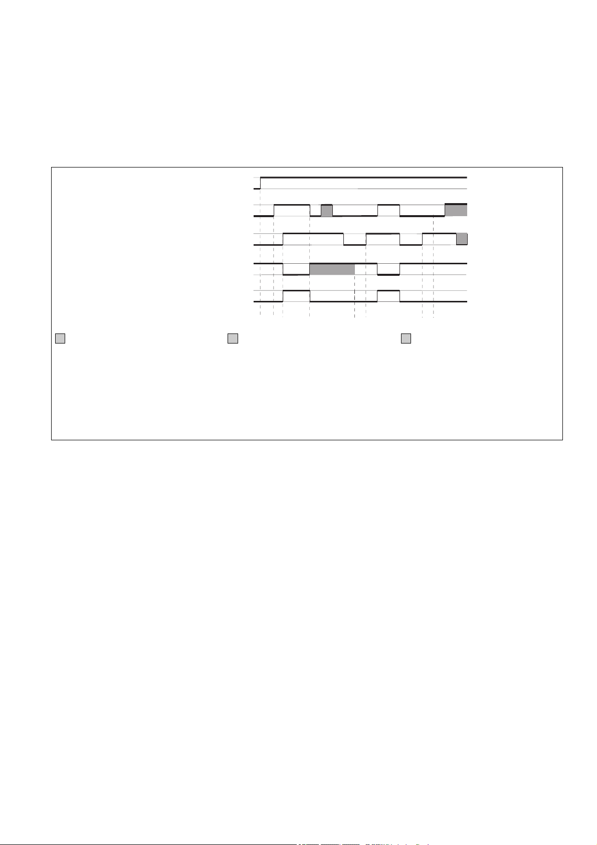
Versorgungsspannung/Operating
Voltage/Tension d'alimentation
Taster 1/Button 1/Poussoir 1
Taster 2/Button 2/Poussoir 2
Rückführkreis Y1, Y2/Feedback Control
Loop/Boucle de retour
Ausgang/Output/Sortie
ohne Bedeutung
Rückführkreis offen: 0
Rückführkreis geschlossen: 1
t0: UB muss mind. 200 ms vor Taster 1
anliegen
t1: Gleichzeitigkeit < 0,5 s (typ. 300 ms)
t2: Arbeitszyklus wird durch Taster 1 oder 2
beendet
t3: Y1-Y2 muss vor Tasterbetätigung
geschlossen sein (Wiederbereitschaftszeit)
Montage
Das Zweihandbedienungsrelais muss in
einen Schaltschrank mit einer Schutzart von
min. IP54 eingebaut werden. Zur Befestigung auf einer Normschiene hat das Gerät
auf der Rückseite ein Rastelement.
ACHTUNG!
Der Abstand der Taster des Zweihandbedienungsrelais von der nächst gelegenen Gefahrenstelle muss so groß
sein, dass beim Loslassen auch nur
eines Tasters die gefährliche Bewegung
unterbrochen wird, bevor der Bediener
die Gefahrenstelle erreicht bzw. bevor der
Bediener in die Gefahrenstelle hineingreifen kann (s. EN 999 "Hand-Arm-Geschwindigkeit").
1
0
1
0
10101
0
1
0
1
1
0
0
t0t
not relevant
Feedback Control Loop open: 0
Feedback Control Loop closed: 1
t0: UB must be supplied at least 200 ms
before button 1 is activated.
t1: Simultaneity < 0.5 s (typ. 300 ms)
t2: Operation cycle ended by either button 1
or button 2
t3: Y1-Y2 must be closed before button is
activated (Recovery Time)
t
1
2
t
3
Installation
The two-hand control relay must be panel
mounted (min IP54). The unit is suitable for
DIN-Rail attachment.
Danger!
The distance of the button connected to
the two-hand relay from the nearest
danger zone must be large enough, that if
one of the buttons is released, the 'close'
command is interrupted before the
operator can reach or reach into the
danger zone (EN 999 "Hand-ArmVelocity").
t
1
indifférent
boucle de retour ouverte: 0
boucle de retour fermée: 1
t0: UB présente min. 200 ms avant action sur
poussoir 1
t1: désynchronisme < 0,5 s (typ. 300 ms)
t2: arrêt cycle par un des 2 poussoirs
t3: Y1-Y2 doit être fermée avant action sur
poussoir (Temps de réarmement)
Montage
Le relais de commande bimanuelle P2HZ X1
doit être installé dans une armoire équipée
d'une protection IP54. La forme de son
boîtier permet un montage facile sur rail DIN
(Oméga).
ATTENTION !
L'implantation du pupitre de commande
doit être telle qu'un opérateur lâchant un
organe de service ne puisse atteindre la
zone dangereuse avant l'arrêt des
éléments mobiles dangereux, compte
tenu de la vitesse d'approche définie dans
la norme EN 999 (NF-E 09-052).
Inbetriebnahme
Beachten Sie bei der Inbetriebnahme:
• Nur die Ausgangskontakte 13-14/23-24/
33-34 sind Sicherheitskontakte.
Ausgangskontakt 41-42 und die
Halbleiterausgänge Y32 und Y35 sind
Hilfsausgänge (z. B. für Anzeige oder
die ungefährliche Aufwärtsbewegung).
• Hilfskontakt 41-42 und Halbleiterausgänge Y32 und Y35 nicht für
Sicherheitsstromkreise verwenden!
• Vor die Ausgangskontakte eine
Sicherung (s. techn. Daten) schalten,
um das Verschweißen der Kontakte zu
verhindern.
Operation
Please note for operation:
• Only the output contacts 13-14/23-24/3334 are safety contacts. Output contact
41-42 and semiconductor outputs Y32
and Y35 are auxiliary outputs (e.g. for
a display or the safe upwards
movement).
• Do not use auxiliary contact 41-42 and
semiconductor outputs Y32 and Y35
for safety circuits!
• To prevent a welding together of the
contacts, a fuse (see technical detail)
must be connected before the output
contacts.
- 3 -
Mise en oeuvre
Informations préliminaires :
• Seuls les contacts 13-14/23-24/33-34
sont des contacts de sécurité. Le
contact 41-42 et les sorties statiques
sont des sorties d'information (ex. :
affichage, pilotage du mouvement de
montée).
• Ne pas utiliser le contact
d’information 41-42 et les sorties
statiques Y32 et Y35 pour les circuits
de commande de sécurité !
• protection des contacts de sortie par
des fusibles (voir les caractéristiques
techniques) normaux pour éviter leur
soudage.
Page 4

• Leitungsmaterial aus Kupferdraht mit einer
Temperaturbeständigkeit von
60/75 °C verwenden.
• Keine kleinen Ströme mit Kontakten schalten, über die zuvor große Ströme geführt
wurden.
• Das Netzteil muss den Vorschriften für
Funktionskleinspannungen mit sicherer
elektrischer Trennung (SELV, PELV) nach
VDE 0100, Teil 410 entsprechen.
• Berechnung der max. Leitungslänge I
Eingangskreis:
R
lmax
=
I
max
Rl / km
R
= max. Gesamtleitungs-
lmax
widerstand (s. technische Daten)
max
Rl /km = Leitungswiderstand/km
• Angaben im Kapitel „Technische Daten“
unbedingt einhalten.
Ablauf:
• Versorgungsspannung an Klemmen A1
(L+) und A2 (L-) anlegen.
Die Versorgungsspannung muss mit der
Antriebsenergie der Maschine (Presse)
abgeschaltet werden.
• Rückführkreis:
Brücke an Y1-Y2 oder externe Schütze
anschließen.
• Eingangskreis
- Taster 1: Öffnerkontakt zwischen S11-
S12 und Schließerkontakt zwischen S11S13 anschließen
- Taster 2: Öffnerkontakt zwischen S21-
S22 und Schließerkontakt zwischen S21S23 anschließen
• Halbleiterausgänge:
+24 V DC an Klemme Y31 und 0 V an
Klemme Y30 anschließen. Y32 und Y35
mit 24-V-Eingängen einer SPS verbinden.
Die Sicherheitskontakte 13-14/23-24/33-34
sind geöffnet, der Hilfskontakt 41-42 ist
geschlossen.
• Use copper wire that can withstand
60/75 °C.
• Low currents should not be switched
across contacts across which high
currents have previously been switched.
• The power supply must comply with the
regulations for extra low voltages with
safe electrical separation (SELV, PELV)
in accordance with VDE 0100, Part 410.
• Calculate the max. Cable runs I
input circuit:
im
R
lmax
=
I
max
Rl / km
R
= Max. Total cable resistance
lmax
(see technical details)
Rl /km = Cable resistance/km
• Important details in the section "Technical
Data" should be noted and adhered to.
To operate:
• Supply operating voltage to terminals A1
(L+) and A2 (L-).
The operating voltage must be turned off
with the driving power of the press.
• Feedback control loop
Bridge Y1 - Y2 or connect external
contactors/relays.
• Input circuit:
- Button 1: Connect N/C contact
between S11-S12 and N/O contact
between S11-S13
- Button 2: Connect N/C contact
between S21-S22 and N/O contact
between S21-S23
• Connect +24 VDC on terminals Y31 and
0 V on terminals Y30. Connect Y32 and
Y35 with 24 V input of a PLC.
The safety contacts 13-14/23-24/33-34 are
opened and the auxilliary contact 41-42 is
closed.
max
in the
• Utiliser uniquement des fils de câblage en
cuivre 60/75 °C.
• Ne pas commuter de faibles intensités
par des contacts ayant au préalable
commutés des intensités plus élevées.
• L'alimentation doit satisfaire aux
prescriptions relatives aux tensions extra
basses avec une isolation électrique de
sécurité (SELV, PELV) selon VDE 0100,
partie 410.
• Calcular les longueurs de câblage max
I
dans le circuit d’entrée:
max
R
lmax
=
I
max
Rl / km
R
= résistivité de câblage totale max.
lmax
(voir les caractéristiques techniques)
Rl /km = résistivité de câblage/km
• Respectez les données indiquées dans les
caractéristiques techniques
Mise en oeuvre :
• Ramenez la tension d'alimentation sur les
bornes A1 (L+) et A2 (L-).
La tension d'alimentation du boîtier doit
être coupée avec la tension de puissance
de la presse.
• Boucle de retour :
Pont sur Y1-Y2 ou branchement des
contacts des contacteurs externes
• Canaux d'entrée :
- Poussoir 1: relier le contact à ouverture
entre S11-S12 et le contact à fermeture
entre S11-S13
- Poussoir 2: relier le contact à ouverture
entre S21-S22 et le contact à fermeture
entre S21-S23
• Sorties statiques
Relier le +24 VDC à la borne Y31 et le 0 V
à la borne Y30. Relier les sorties Y32 et
Y35 à des entrées 24 V API.
Les contacts de sécurité 13-14/23-24/33-34
sont ouverts, le contact d'info. 41-42 est
fermé.
Fehler - Störungen
Das Gerät kann aus Sicherheitsgründen bei
folgenden Fehlern nicht gestartet werden:
• Verschweißte Kontakte
• Defekte Spule
• Leiterbruch
• Kurzschluss z. B. zwischen den Tastern
• Nicht Einhalten der Gleichzeitigkeit
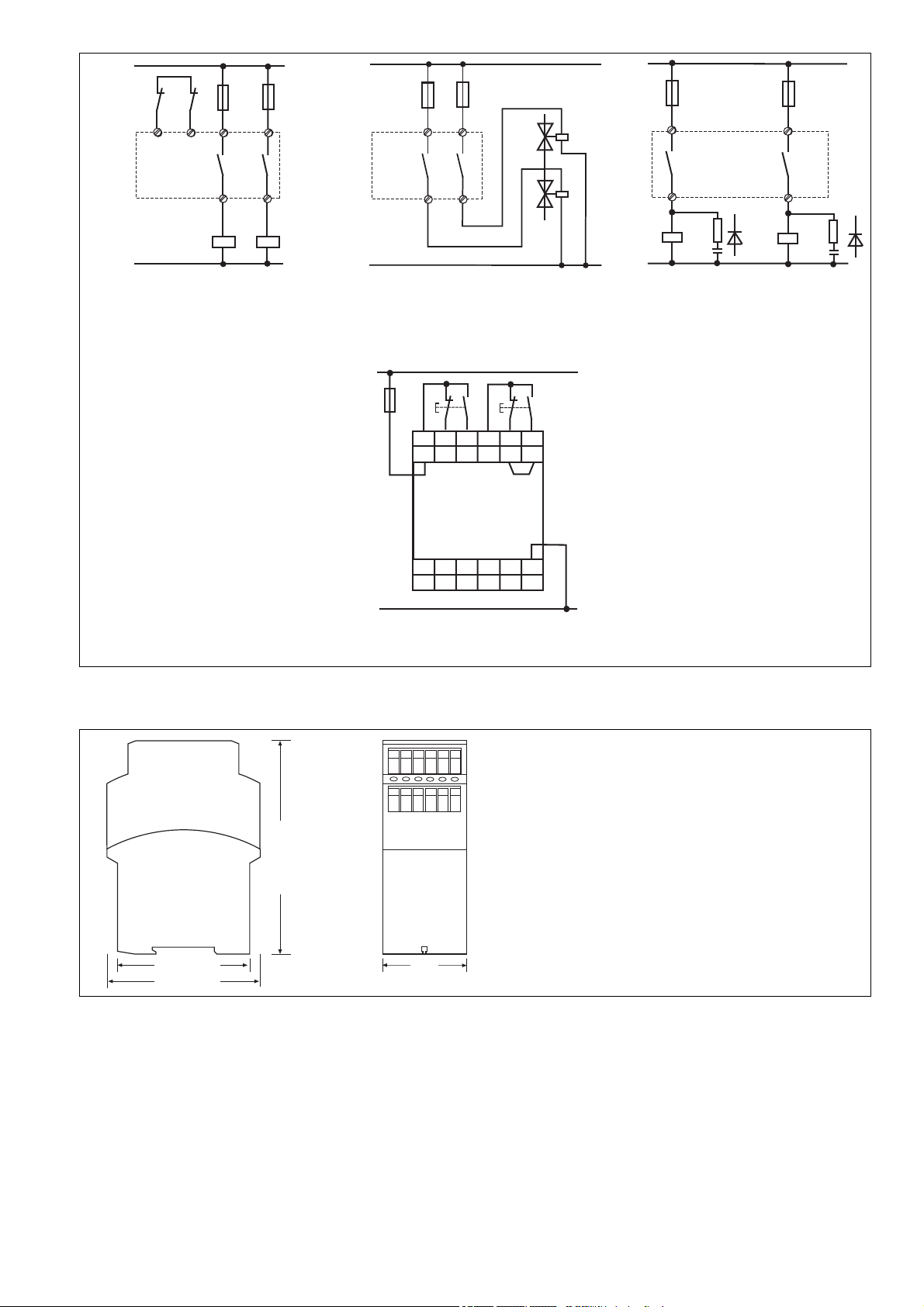
Anwendungen
Gerät nur wie in den folgenden Beispielen beschrieben anschließen!
Kontaktbelastung s. technische Daten
Fig. 2: Hilfskontakte in Reihe zu Y1-Y2; K5
und K6 müssen zwangsgeführte Schütze
sein.
Kontaktabsicherung F1 und F2 s. technische
Daten
Fig. 4: Beim Schalten induktiver Lasten wie
Relais oder Schütze muss ein Funkenlöschglied parallel zur Induktivität geschaltet
werden.
Nicht parallel zu Ausgangskontakt schalten!
AC: Funkenlöschung z. B. durch RC-Glied
DC: Funkenlöschung z. B. durch Freilaufdiode
Fig. 5: F3 min. 1 A, max. abhängig vom
Leitungsquerschnitt
Faults
For safety reasons, the unit will not
energise when the following faults occur:
• Welded contacts
• Defective coil
• Cable-break
• Short-circuit e.g. between the buttons
• Simultaneity not upheld
Application
Only connect the unit as shown in the
examples below!
See technical details for contact load and
fusing
Fig. 2: Auxiliary contacts in series with Y1Y2; K5 and K6 must be positive-guided
contactors.
Contact Fuse Protection F1 and F2 see
technical details
Fig. 4: When switching inductive loads such
as relays or contactors, a spark
suppression element must be wired parallel
to the load. Do not wire parallel to output
contacts!
AC: Spark suppression e. g. via RC element
DC: Spark suppression e. g. via recovery
diode
Fig. 5: F3 min. 1 A, max.dependent on
cable cross section
Erreurs - Défaillances
Compte tenu de sa fonction de sécurité,
l'appareil ne peut être activé après les
défaillances suivantes :
• Collage d'un contact
• Défaillance d'une bobine
• Rupture d'une piste de circuit imprimé
• Court-circuit entre les poussoirs
• non respect du synchronisation
temporelle.
Utilisation
Les exemples de branchement cidessous doivent être respectés!
Pouvoir de coupure et protection des
contacts de sortie, voir caract. techniques
Fig. 2: Contacts en série entre Y1-Y2; K5 et
K6 sont des relais à contacts liés.
Protection des contacts F1 et F2, voir caract.
techniques
Fig. 4: En cas de commande des charges
inductives (relais ou contacteurs), des
dispositifs d´extinction d´arc doivent être
montés en parallèle sur la charge. Ne pas
monter ces dispositifs en parallèle sur le
contacts de sortie.
AC: extinction d'arc par circuit RC
DC: extinction d'arc par diode de roue libre.
Fig. 5: F3 min. 1 A, max. dépend du diam.
du câble.
- 4 -
Page 5
L1
K5 K6
Y1 Y2
L1
F1
F1
F2
13
23
F1
13
23
L1
F1
13
F2
23
24
14
K5 K6
N
Fig. 2: Zweikanalige Ansteuerung; 2 S;
Two-channel drive; 2 N/O;
Commande par 2 canaux; 2 F ;
14
24
N
Fig. 3: Ansteuerung einer Last
Load Control
Commande d´une seule charge
L+/L1
S1 S2
F3
S23
Y2
A2
L-/N
S11
S12 S13 S21 S22
A1
13 23 33 Y1
14
24 34 41 42
Y30
Y31 Y32 Y35
Fig. 5: Anschlussbeispiel/Connection example/
Branchement
14
L
N
R
C
Fig. 4: Funkenlöschung
Spark suppression
Extinction d'arc
24
L
R
C
Abmessungen in mm ('')/Dimensions in mm ('')/Dimensions en mm ('')
122 (4.8")
75 (2.95")
87 (3.42")
45
(1.77")
- 5 -
Page 6

Technische Daten
Technical Data
Caractéristiques techniques
Elektrische Daten
Versorgungsspannung U
B
Spannungstoleranz
Leistungsaufnahme bei U
B
Frequenzbereich
Restwelligkeit
Spannung und Strom an
Eingangskreis
Öffner:
Schließer:
Rückführkreis
Anzahl der Ausgangskontakte
Sicherheitskontakte (S)
Hilfskontakte (Ö)
Gebrauchskategorie nach
EN 60947-4-1
Sicherheitskontakte
Hilfskontakte
EN 60947-5-1(DC13:
6 Schaltspiele/Min.)
Sicherheitskontakte
Hilfskontakte
Konventioneller thermischer Strom
Kontaktmaterial
Kontaktabsicherung extern
EN 60947-5-1 (IK = 1 kA)
Sicherheitskontakte:
Schmelzsicherung flink
Schmelzsicherung träge
Sicherungsautomat
Charakteristik
Hilfskontakte:
Schmelzsicherung flink
Schmelzsicherung träge
Sicherungsautomat
Charakteristik
Halbleiterausgänge (kurzschlussfest)
Externe Spannungsversorgung
Spannungstoleranz
Max. Gesamtleitungswiderstand
R
(Eingangskreis)
lmax
Sicherheitstechnische Kenndaten der Sicherheitsausgänge
PL nach EN ISO 13849-1:2008
Kategorie nach EN ISO 13849-1
SIL CL nach EN IEC 62061
PFH nach EN IEC 62061
SIL nach IEC 61511
PFD nach IEC 61511
EN ISO 13849-1:2008 TM [Jahr]
Zeiten
Rückfallverzögerung
(Ansprechzeit nach EN 574)
Öffner:
Schließer:
Wiederbereitschaftszeit
Gleichzeitigkeit Kanal 1 und 2
Electrical data
Supply Voltage U
B
Voltage Tolerance
Power consumption at U
B
Frequency Range
Residual Ripple
Voltage and Current at
Input circuit
N/C:
N/O:
Feedback loop
Number of output contacts
Safety contacts (N/O)
Auxiliary contacts (N/C)
Utilization category in accordance with
EN 60947-4-1
Safety contacts
Auxiliary contacts
EN 60947-5-1(DC13:
6 cycles/min)
Safety contacts
Auxiliary contacts
Conventional thermal current
Contact material
External contact fuse protection
EN 60947-5-1 (IK = 1 kA)
Safety contacts:
Blow-out fuse quick
Blow-out fuse slow
Safety cut-out
Characteristic
Auxiliary contacts:
Blow-out fuse quick
Blow-out fuse slow
Safety cut-out
Characteristic
Semiconductor outputs (short
circuit-proof)
External supply voltage
Voltage tolerance
Max. overall cable resistance R
(input circuit)
lmax
Safety-related characteristics of
the safety outputs
PL in accordance with
EN ISO 13849-1:2008
Category in accordance with
EN ISO 13849-1
SIL CL in accordance with
EN IEC 62061
PFH in accordance with
EN IEC 62061
SIL in accordance with IEC 61511
PFD in accordance with IEC 61511
EN ISO 13849-1:2008 TM [year]
Times
Delay-on De-Energisation
(Reaction time to EN 574)
N/C:
N/O:
Recovery time
Simultaneity channel 1 and 2
Données électriques
Tension d’alimentation U
B
Plage de la tension d’alimentation
Consommation pour U
B
Fréquence
Ondulation résiduelle
Tension et courant du
Circuit d’entrée
Ouverture:
Fermeture:
boucle de retour
Nombre de contacts de sortie
contacts de sécurité (F)
contact d'info (O)
Catégorie d’utilisation selon
EN 60947-4-1
Contacts de sécurité
Contact d'info
EN 60947-5-1(DC13:
6 manoeuvres/min)
Contacts de sécurité
Contact d'info
Courant thermique conventionnel
Matériau contact
Protection des contacts externe
EN 60947-5-1 (IK = 1 kA)
Contacts de sécurité:
Fusibles rapide
Fusibles normal
Dijoncteur
Caractéristique
Contact d'info:
Fusibles rapide
Fusibles normal
Dijoncteur
Caractéristique
Sorties statiques (protégées
contre c.c.)
Tension d’alimentation externe
Plage de la tension d’alimentation
Résistance de câblage totale max.
R
(circuit d'entrée)
lmax
Caractéristiques techniques de
sécurité des sorties de sécurité
PL selon EN ISO 13849-1:2008
Catégorie selon EN ISO 13849-1
SIL CL selon EN IEC 62061
PFH selon EN IEC 62061
SIL selon IEC 61511
PFD selon IEC 61511
EN ISO 13849-1:2008 TM [an]
Temporisations
Temps de retombée
(Temps d’appel d'après prEN 574)
Ouverture:
Fermeture:
Temps de remise en service
Désynchronisme canal 1 et 2
AC: 24, 42, 48, 110, 115
120, 230, 240 V
DC: 24 V, 26 V
-15 ... +10 %
AC: 6 VA
DC: 2,5 W
AC: 50 ... 60 Hz
DC: 10 %
24 V DC: 20 mA
24 V DC: 30 mA
24 V DC: 45 mA
3
1
AC1: 240 V/0,01 ... 5 A/
1250 VA
DC1: 24 V/0,01 ... 5 A/
125 W
AC1: 240 V/0,01 ... 2 A/
500 VA
DC1: 24 V/0,01 ... 2 A/
50 W
AC15: 230 V/2,5 A;
DC13: 24 V/1,5 A
AC15: 230 V/2 A;
DC13: 24 V/1,5 A
5,0 A
AgSnO2+ 0,2 µm Au
6 A
4 A
24 V AC/DC: 4 A
B/C
4 A
2 A
24 V AC/DC: 2 A
B/C
24 V DC / 20 mA
24 V DC
-15 % / +10 %
14 Ohm
PL e
Cat. 4
SIL CL 3
3,01E-09
SIL 3
3,24E-06
20
30 ms
15 ms
250 ms
500 ms
- 6 -
Page 7

Umweltdaten
EMV
Schwingungen nach EN 60068-2-6
Frequenz
Amplitude
Klimabeanspruchung
Luft- und Kriechstrecken nach
EN 60947-1
Verschmutzungsgrad
Überspannungskategorie
Bemessungsisolationsspannung
Bemessungsstoßspannungs-festigkeit
Umgebungstemperatur
Lagertemperatur
Schutzart
Einbauraum (z. B. Schaltschrank)
Gehäuse
Klemmenbereich
Mechanische Daten
Gehäusematerial
Gehäuse
Front
Querschnitt des Außenleiters
(Schraubklemmen)
1 Leiter, flexibel
2 Leiter gleichen Querschnitts, fle-
xibel mit Aderendhülse, ohne
Kunststoffhülse
ohne Aderendhülse oder mit TWIN-
Aderendhülse
Anzugsdrehmoment für
Schraubklemmen
Abmessungen (Schraubklemmen)
H x B x T
Einbaulage
Gewicht
Environmental data
EMC
Vibration to EN 60068-2-6
Frequency
Amplitude
Climate Suitability
Airgap Creepage in accordance with
EN 60947-1
Pollution degree
Overvoltage category
Rated insulation voltage
Rated impulse withstand voltage
Ambient temperature
Storage temperature
Protection type
Mounting (eg. panel)
Housing
Terminals
Mechanical data
Housing material
Housing
Front panel
Cable cross section (screw
terminals)
1 core, flexible
2 core, same cross section flexible
with crimp connectors, without
insulating sleeve
without crimp connectors or with
TWIN crimp connectors
Torque setting for screw terminals
Dimensions (screw terminals)
H x W x D
Fitting Position
Weight
Données sur l'environnement
CEM
Vibrations selon EN 60068-2-6
Frequence
Amplitude
Conditions climatiques
Cheminement et claquage selon
EN 60947-1
Niveau d'encrassement
Catégorie de surtensions
Tension assignée d'isolement
Tension assignée de tenue aux chocs
Température d’utilisation
Température de stockage
Indice de protection
Lieu d'implantation (ex. armoire)
Boîtier
Bornes
Données mécaniques
Matériau du boîtier
Boîtier
Face avant
Capacité de raccordement
(borniers à vis)
1 conducteur souple
2 conducteurs de même diamètre
souple avec embout, sans
chapeau plastique
souple sans embout ou avec
embout TWIN
Couple de serrage (borniers à vis)
Dimensions (borniers à vis)
H x P x L
Position de travail
Poids
EN 60947-5-1,
EN 61000-6-2
10 ... 55 Hz
0,35 mm
EN 60068-2-78
2
III
250 V
4 kV
-25 ... +55 °C
-40 ... +85 °C
IP54
IP40
IP20
PPO UL 94 V0
ABS UL 94 V0
0,2 ... 4,0 mm2, 24 - 10 AWG
0,2 ... 2,5 mm2, 24 - 14 AWG
0,2 ... 2,5 mm2, 24 - 14 AWG
0,6 Nm
87 x 45 x 121 mm
beliebig/any/indifférente
AC: 380 g
DC: 280 g
No. ist gleichbedeutend mit Bestell-Nr.
ACHTUNG!
Beachten Sie unbedingt die
Lebensdauerkurve der Relais. Die
sicherheitstechnischen Kennzahlen
der Relaisausgänge gelten nur,
solange die Werte der Lebensdauer-
kurven eingehalten werden.
Der PFH-Wert ist abhängig von der
Schaltfrequenz und der Belastung des
Relaisausganges. Solange die
Lebensdauerkurven nicht erreicht werden,
kann der angegebene PFH-Wert unabhängig von der Schaltfrequenz und der
Belastung verwendet werden, da der PFHWert den B10d-Wert der Relais sowie die
Ausfallraten der anderen Bauteile bereits
berücksichtigt.
Alle in einer Sicherheitsfunktion verwendeten Einheiten müssen bei der Berechnung
der Sicherheitskennwerte berücksichtigt
werden.
INFO
Die SIL-/PL-Werte einer Sicherheits-
funktion sind nicht identisch mit den
SIL-/PL-Werten der verwendeten
Geräte und können von diesen
abweichen. Wir empfehlen zur
Berechnung der
SIL-/PL-Werte der Sicherheitsfunktion das Software-Tool PAScal.
Es gelten die 2010-07 aktuellen Ausgaben
der Normen
No. stands for order number. No. correspond à la référence du produit.
CAUTION!
It is essential to consider the relay’s
service life graphs. The relay
outputs’ safety-related characteristic
data is only valid if the values in the
service life graphs are met.
The PFH value depends on the switching
frequency and the load on the relay output.
If the service life graphs are not accessible,
the stated PFH value can be used
irrespective of the switching frequency and
the load, as the PFH value already
considers the relay’s B10d value as well as
the failure rates of the other components.
All the units used within a safety function
must be considered when calculating the
safety characteristic data.
INFORMATION
A safety function’s SIL/PL values are
not identical to the SIL/PL values of
the units that are used and may be
different. We recommend that you
use the PAScal software tool to
calculate the safety function’s SIL/PL
values.
The version of the standards current at
2010-07 shall apply
ATTENTION!
Veuillez absolument tenir compte des
courbes de durée de vie des relais. Les
caractéristiques de sécurité des sorties
relais sont uniquement valables tant que
les valeurs des courbes de durée de
vie sont respectées.
La valeur PFH dépend de la fréquence de
commutation et de la charge de la sortie
relais.
Tant que les courbes de durée de vie ne
sont pas atteintes, la valeur PFH indiquée
peut être utilisée indépendamment de la
fréquence de commutation et de la charge
car la valeur PFH prend déjà en compte la
valeur B10d des relais ainsi que les taux de
défaillance des autres composants.
Toutes les unités utilisées dans une fonction
de sécurité doivent être prises en compte
dans le calcul des caractéristiques de
sécurité.
INFORMATION
Les valeurs SIL / PL d’une fonction
de sécurité ne sont identiques aux
valeurs SIL / PL des appareils
utilisés et peuvent varier par rapport
à celles-ci. Pour le calcul des
valeurs SIL / PL de la fonction de
sécurité, nous recommandons l’outil
logiciel PAScal.
Se référer à la version des normes en
vigeur au 2010-07.
- 7 -
Page 8

Lebensdauerkurve
Die Lebensdauerkurven geben an, ab
welcher Schaltspielzahl mit verschleißbedingten Ausfällen gerechnet werden
muss. Der Verschleiß wird vor allem durch
die elektrische Belastung verursacht, der
mechanische Verschleiß ist
vernachlässigbar.
Service life graph
The service life graphs indicate the number
of cycles from which failures due to wear
must be expected. The wear is mainly
caused by the electrical load; the
mechanical load is negligible.
Courbe de durée de vie
Les courbes de durée de vie indiquent à
partir de quel nombre de manoeuvres il faut
s’attendre à des défaillances liées à l’usure.
La charge électrique est la cause principale
de l’usure, l’usure mécanique étant
négligeable.
Beispiel:
Induktive Last: 0,2 A
Gebrauchskategorie: AC15
Lebensdauer der Kontakte: 4 000 000
Schaltspiele
Solange die zu realisierende Applikation nur
eine Schaltspielzahl von weniger als
4 000 000 Schaltspielen erfordert, kann mit
dem PFH-Wert (s. technische Daten)
gerechnet werden.
Um die Lebensdauer zu erhöhen, an allen
Ausgangskontakten für eine ausreichende
Funkenlöschung sorgen. Bei kapazitiven
Lasten sind eventuell auftretende Stromspitzen zu beachten. Bei DC-Schützen
Freilaufdioden zur Funkenlöschung
einsetzen.
Example:
Inductive load: 0,2 A
Utilisation category: AC15
Contact service life: 4,000,000 cycles
Provided the application requires fewer than
4,000,000 cycles, the PFH value (see
technical details) can be used in the
calculation.
To increase the service life, sufficient spark
suppression must be provided on all output
contacts. With capacitive loads, any power
surges that occur must be noted. With
contactors, use freewheel diodes for spark
suppression.
Exemple:
Charge inductive : 0,2 A
Catégorie d’utilisation : AC15
Durée de vie des contacts : 4 000 000
manoeuvres
Tant que l’application à réaliser requière un
nombre de manoeuvres inférieur à
4 000 000, on peut se fier à la valeur PFH
(voir les caractéristiques techniques).
Assurez-vous qu’il y ait une extinction d’arc
suffisante sur tous les contacts de sortie
afin d’augmenter la durée de vie. Faites
attention à l’apparition de pointes de courant
en cas de charges capacitatives. En cas de
contacteurs DC, utilisez des diodes de roue
libre pour l’extinction des étincelles.
- 8 -
Page 9

Bestelldaten/Order reference/Caractéristiques
Typ/
Type/
Type
P2HZ X1
P2HZ X1
P2HZ X1
P2HZ X1
P2HZ X1
P2HZ X1
P2HZ X1
P2HZ X1
P2HZ X1
P2HZ X1
Merkmale/
Features/
Caractéristiques
24 V AC
42 V AC
48 V AC
110 V AC
115 V AC
120 V AC
230 V AC
240 V AC
EG-Konformitätserklärung:
Diese(s) Produkt(e) erfüllen die Anforderungen der Richtlinie 2006/42/EG über
Maschinen des europäischen Parlaments
und des Rates.
Die vollständige EG-Konformitätserklärung
finden Sie im Internet unter www.pilz.com
Bevollmächtigter: Norbert Fröhlich,
Pilz GmbH & Co. KG, Felix-Wankel-Str. 2,
73760 Ostfildern, Deutschland
Klemmen/
Terminals/
Borniers
Schraubklemmen/screw terminals/borniers à vis
Schraubklemmen/screw terminals/borniers à vis
Schraubklemmen/screw terminals/borniers à vis
Schraubklemmen/screw terminals/borniers à vis
Schraubklemmen/screw terminals/borniers à vis
Schraubklemmen/screw terminals/borniers à vis
Schraubklemmen/screw terminals/borniers à vis
Schraubklemmen/screw terminals/borniers à vis
24 V DC
26 V DC
Schraubklemmen/screw terminals/borniers à vis
Schraubklemmen/screw terminals/borniers à vis
EC Declaration of Conformity:
This (these) product(s) comply with the
requirements of Directive 2006/42/EC of the
European Parliament and of the Council on
machinery.
The complete EC Declaration of Conformity
is available on the Internet at www.pilz.com
Authorised representative: Norbert Fröhlich,
Pilz GmbH & Co. KG, Felix-Wankel-Str. 2,
73760 Ostfildern, Germany
Bestell-Nr./
Order no./
Référence
774 330
774 331
774 332
774 434
774 435
774 436
774 438
774 439
774 340
774 341
Déclaration de conformité CE :
Ce(s) produit(s) satisfait (satisfont) aux
exigences de la directive 2006/42/CE
relative aux machines du Parlement
Européen et du Conseil.
Vous trouverez la déclaration de conformité
CE complète sur notre site internet
www.pilz.com
Représentant : Norbert Fröhlich,
Pilz GmbH & Co. KG, Felix-Wankel-Str. 2,
73760 Ostfildern, Allemagne
- 9 -
Page 10

Technischer Support
+49 711 3409-444 +49 711 3409-444
...
In vielen Ländern sind wir durch
unsere Tochtergesellschaften und
Handelspartner vertreten.
Nähere Informationen entnehmen
Sie bitte unserer Homepage oder
nehmen Sie Kontakt mit unserem
Stammhaus auf.
Technical support
... ...
In many countries we are
represented by our subsidiaries
and sales partners.
Please refer to our Homepage
for further details or contact our
headquarters.
Assistance technique
+49 711 3409-444
Nos filiales et partenaires
commerciaux nous représentent
dans plusieurs pays.
Pour plus de renseignements,
consultez notre site internet ou
contactez notre maison mère.
- 10 -
www
www.pilz.com
Pilz GmbH & Co. KG
Felix-Wankel-Straße 2
73760 Ostfildern, Germany
Telephone: +49 711 3409-0
Telefax: +49 711 3409-133
E-Mail: pilz.gmbh@pilz.de
Originalbetriebsanleitung/Original instructions/Notice originale
20124-6NL-05, 2013-09 Printed in Germany
Page 11

20124-6NL-05
P2HZ X1
4 E Instrucciones de uso
4 I Istruzioni per l'uso
4 NL Gebruiksaanwijzing
Prescripciones de seguridad
• El dispositivo debe ser instalado y puesto en
funcionamiento exclusivamente por personas que estén familiarizadas tanto con estas
instrucciones de uso como con las prescripciones vigentes relativas a la seguridad en el
trabajo y a la prevención de accidentes.
servar tanto las prescripciones VDE como
las prescripciones locales, especialmente
respecto a las medidas de protección.
• Durante el transporte, el almacenaje y el
funcionamiento hay que atenerse a las condiciones conforme a EN 60068-2-6 (ver datos
técnicos). Una vez finalizado su tiempo de
vida útil, hay que eliminar el dispositivo de
forma apropiada.
• La garantía se pierde en caso de que se
abra la carcasa o se lleven a cabo
remodelaciones por cuenta propia.
• Montar el dispositivo dentro de un armario de
distribución; en caso contrario es posible que
el polvo y la suciedad puedan afectar el funcionamiento.
• Cuidar de que haya un conexionado de seguridad suficiente en todos los contactos de
salida con cargas capacitivas e inductivas.
• El dispositivo de a dos manos y las partes
del control de la prensa conectadas delante
y detrás tienen que corresponderse con las
prescripciones VDE pertinentes y con las
reglas de seguridad EN 574; EN 692 y EN
693.
• La tensión de servicio alimentación del relé
de manejo a dos manos sólo debe conectarse después del dispositivo de desconexión
en conformidad con art. 9 VBG 7n5.1/2.
• No tender el cable de conexión entre
P2HZ X1 y los pulsadores inmediatamente
junto a líneas de corriente de alta tensión; en
tal caso podrían producirse acoplamientos
parasitarios inductivos y capacitivos.
• Debido a reducidas corrientes hay que utilizar contactos de pulsador con oro laminado.
• Sólo se permite conectar el dispositivo exclusivamente como en los ejemplos de conexión del capítulo “Aplicaciones”.
Ob-
Norme di sicurezza
• Il dispositivo può venire installato e messo
in funzione solo da persone che
conoscono bene le presenti istruzioni per
l’uso e le disposizioni vigenti relative alla
sicurezza di lavoro e all’antinfortunistica.
Osservare le disposizioni della VDE
(Associazione tedesca degli Ingegneri)
nonché le norme locali, soprattutto per
quanto riguarda le misure preventive di
protezione.
• Durante il trasporto, l’immagazzinamento e
il funzionamento attenersi alle condizioni
prescritte dalla norma EN 60068-2-6
(v. Dati tecnici). Al termine della propria
durata, smaltire il dispositivo in conformità
alle norme vigenti.
• Se viene aperto l’alloggiamento oppure se
vengono apportate delle modifiche in
proprio decade qualsiasi diritto di garanzia.
• Montare il dispositivo in un armadio
elettrico; altrimenti la polvere e l’umidità
possono pregiudicare le funzioni.
• Occorre dotare tutti i contatti di uscita dei
carichi capacitivi e induttivi con un
cablaggio protettivo sufficiente.
• Il comando bimanuale e le parti del
comando della pressa collegate devono
rispettare le disposizioni e le norme di
sicurezza EN 574; EN 692 e EN 693.
• La tensione di alimentazione del relè a comando bimanuale può solo essere collegata secondo le prescrizioni § 9 VBG
7n5.1/2.
• Non posare assolutamente il cavo di collegamento tra il P2HZ X1 e gli elementi di
comando vicino a cavi di corrente forte,
per evitare interferenze induttive o
capacitive.
• Per evitare basse correnti i contatti degli
elementi di comando devono essere dorati.
• Il dispositivo può essere collegato solo
come indicato negli esempi di connessione
al capitolo “Utilizzo”.
Veiligheidsvoorschriften
• Het apparaat mag uitsluitend worden
geïnstalleerd en in bedrijf genomen door
personen die vertrouwd zijn met deze
gebruiksaanwijzing en met de gel-dende
voorschriften op het gebied van arbeidsveiligheid en ongevallenpreventie.
de VDE-voorschriften alsmede de plaatselijke voorschriften in acht, in het bijzonder
m.b.t. de veiligheidsregels.
• Neem bij transport, opslag en in bedrijf de
richtlijnen volgens EN 60068-2-6 in acht
(zie technische gegevens). Het apparaat
na afloop van zijn levensduur op de juiste
wijze verwijderen en opslaan.
• Het openen van de behuizing of het eigenmachtig aanpassen heeft verlies van de
garantie tot gevolg.
• Monteer het apparaat in een schakelkast.
Stof en vocht kunnen anders de werking
nadelig beïnvloeden.
• Zorg bij alle uitgangscontacten bij capacitieve en inductieve belastingen voor voldoende beschermbedrading.
• De tweehandenschakeling en de ervoor
en erachter aangebrachte onderdelen van
de persbestu-ring moeten beantwoorden
aan de desbetreffende VDE-voorschriften
en de veiligheidsregels EN 574;
EN 692 en EN 693.
• De voedingsspanning van het tweehandenbedieningsrelais mag uitsluitend na
de uit schakelinrichting overeenkomstig
§ 9 VBG 7n5-1/2 worden aangesloten.
• Monteer de verbindingskabels tussen
P2HZ X1 en de knoppen niet direct naast
sterkstroomkabels; hierdoor kunnen inductieve en capacitieve stoorkoppelingen
ontstaan.
• Gebruik wegens de geringe stromen
vergulde tastercontacten.
• Het apparaat mag alleen worden aangesloten zoals in de aansluitvoorbeelden in het
hoofdstuk “Toepassingen” is beschreven.
Neem
Campo de aplicación adecuado
P2HZ X1 satisface los requerimientos del tipo
III C según EN 574. El relé de manejo a dos
manos obliga al operario de una prensa a
mantener las manos fuera de la zona de
peligro mientras que tienen lugar los
movimientos peligrosos de cierre, con objeto
de evitar lesiones en las manos.
P2HZ X1 es adecuado para su montaje en
controles para prensas para el trabajo de
metales como módulo de simultaneidad.
El dispositivo puede ser utilizado como dispositivo de protección de las manos en
conformidad con las reglas técnicas
• Prensas excéntricas y similares
(EN 692)
• Prensas hidráulicas (EN 693)
• Prensas de husillo (EN 692)
o bien en
• Circuitos de seguridad según EN 60204-1;
VDE 0113-1.
Uso previsto
Il P2HZ X1 rispetta i requisiti della norma
EN 574 Tipo III C. Il relè a comando
bimanuale obbliga l’operatore di una pressa a
mantenere le mani all’esterno della zona
pericolosa durante il movimento della
macchina per evitare ferite alle mani.
Il P2HZ X1 deve essere montato in sistemi di
controllo per presse destinate alla
lavorazione dei metalli per garantire la
funzione di simultaneità.
L’unità può essere utilizzata come dispositivo
per la protezione delle mani secondo le prescrizioni delle norme tecniche
• Presse eccentriche e simili
(EN 692)
• presse idrauliche (EN 693)
• presse a vite (EN 692)
oppure in
• circuiti elettrici di sicurezza secondo la norma EN 60204-1; VDE 0113-1.
- 11 -
Toegelaten applicaties
P2HZ X1 beantwoordt aan de eis volgens
EN 574, 11/96 type III C. Ter voorkoming
van verwondingen aan de handen dwingt het
tweehandenbedieningsrelais de gebruiker
van een pers om zijn handen tijdens de
gevaarlijke sluitbeweging buiten de
gevarenzone te houden.
P2HZ X1 is als bouwsteen van de gelijktij-
digheid geschikt voor het inbouwen in besturingen voor persen in de metaalbewerking.
Volgens de technische voorschriften kan het
apparaat als handbescherming bij
• “excenterpersen en gelijksoortige
persen”
(EN 692)
• hydraulische persen (EN 693)
• spilpersen (EN 692)
of in
• veiligheidsstroomcircuits volgens
EN 60204-1, VDE 0113-1
worden gebruikt.
Page 12

Se entiende como aplicación no correcta, en
particular:
•
toda modificación constructiva, técnica o
eléctrica de un producto
•
el uso de un producto fuera de las zonas
descritas en la documentación del mismo
•
todo uso diferente de los datos técnicos
documentados.
Tra gli utilizzi non previsti in particolare
•
qualsiasi modifica strutturale, tecnica o
elletrica di un prodotto
•
l'impiego del prodotto al di fuori dei settori
descritti nella documentazione del prodotto
•
un utilizzo che si discosta dai dati tecnici
documentati.
Als niet volgens de voorschriften gelden in
het bijzonder:
•
elke bouwkundige, technische of elektrische wijziging van een product
•
het gebruik van een product buiten de
bereiken die in deze productdocumentatie
beschreven zijn
•
een gebruik dat afwijkt van de
gedocumenteerde gegevens.
Descripción del dispositivo
El relé de manejo a dos manos se encuentra
dentro de una carcasa P-97. Existen
diversas variantes disponibles para el
funcionamiento con tensión alterna y una
variante para el funcionamiento con tensión
continua.
Características:
• Salidas de relé:
3 contactos de seguridad (normalmente
abiertos) y un contacto auxiliar
(normalmente cerrado), con guía forzada
• Las salidas por semiconductor avisan del
estado de los relés de salida y de la
tensión de alimentación
• Indicador de estado para relé de salida y
tensión de alimentación
• Circuito de realimentación para la supervisión
de contactores externos
El relé de manejo a dos manos cumple con los
siguientes requerimientos de seguridad:
• El cableado está estructurado de modo
redundante con autosupervisión
• El equipo de seguridad permanece activo
aún cuando falle uno de los componentes
• El circuito evita otra carrera de prensa en
caso de fallo de relé, fusión de un contacto,
defecto de bobina de un relé, rotura de
conductor, cortocircuito
Descrizione
Il relè di comando bimanuale è inserito in un
alloggiamento P-97. Per il funzionamento a
corrente alternata sono disponibili diverse
varianti ed una variante per il funzionamento
con corrente continua.
Caratteristiche:
• Uscite relè:
3 contatti di sicurezza (NA) e un contatto
ausiliario (NC) a guida positiva
• Le uscite del semiconduttore indicano lo
stato del relè di uscita e della tensione di
alimentazione
• Indicatore di stato per il relè di uscita e la
tensione di alimentazione
• Circuito di retroazione per il controllo di
relè esterni
Il relè a comando bimanuale risponde ai
seguenti requisiti di sicurezza:
• il circuito è strutturato in modo ridondante
con autocontrollo
• il dispositivo di sicurezza funziona anche in
caso di guasto di un componente
• il circuito impedisce una ulteriore corsa della
pressa in caso di problema al relè, la saldatura di un contatto, il difetto della bobina di un
relè, la rottura dei cavi, il cortocircuito
Apparaatbeschrijving
Het tweehandenbedieningsrelais is ondergebracht in een P-97-behuizing. Er zijn verschillende varianten voor de werking met
wisselspanning beschikbaar en één variant
voor de werking met gelijkspanning.
Kenmerken:
• Relaisuitgangen:
3 veiligheidscontacten (werkcontacten) en
een hulpcontact (opener), mechanisch
gedwongen
• Halfgeleideruitgangen melden de toestand
van de uitgangsrelais en van de voedingsspanning
• Statusweergave voor uitgangsrelais en
voedingsspanning
• Terugkoppelcircuit ter bewaking van
externe relais
Het tweehandenbedieningsrelais voldoet aan
de volgende veiligheidseisen:
• De schakeling is redundant met zelfcon-trole
opgebouwd
• Ook bij uitvallen van een component blijft de
veiligheidsschakeling werken
• De schakeling voorkomt nog een persslag bij
weigering van het relais, ver-binding van een
contact, spoeldefect van een relais, geleiderbreuk, kortsluiting
Descripción de funciones
El relé de manejo a dos manos tiene que activarse accionando dos pulsadores simultáneamente. Al soltar uno o ambos pulsadores,
ello tiene como efecto la interrupción de la
orden de control de cerrar la prensa. El
movimiento de cierre puede iniciarse de
nuevo sólo después de que ambos
pulsadores hayan retornado (soltándolos) a
su posición de partida y hayan sido entonces
accionados de nuevo.
Fig. 1: Plano de conexiones interno /
Schema delle connessioni /
Intern schakelschema
Descrizione del funzionamento
Il relè a comando bimanuale deve essere
attivato con la pressione simultanea di due
pulsanti. Con il rilascio di uno o di entrambi i
pulsanti viene interrotto l’impulso di comando
per la chiusura della pressa. Il movimento può
nuovamente essere attivato dopo che entrambi
i pulsanti sono tornati nella posizione di partenza (o sono stati rilasciati) e nuovamente
premuti.
Y31
Y35
Y32
Y30
A2
A1
T1
+
~
=
S12
S11
S13
Lógica de control / Logica di
controllo / Besturingslogica
Canal / Canale /
Kanaal 1
K2
K1
Functiebeschrijving
Het tweehandenbedieningsrelais wordt geactiveerd door het gelijktijdig indrukken van
twee knoppen. Bij het loslaten van een of van
beide knoppen wordt het startcommando
voor het sluiten van de pers onderbroken. De
sluitbeweging wordt pas weer in gang gezet,
nadat beide knoppen naar hun
uitgangspositie zijn teruggekeerd (losgelaten)
en opnieuw worden ingedrukt.
Y1
K1
Y2
S21
Canal / Canale /
Kanaal 2
S22
S23
K2
33
23
13
14
41
34
24
42
- 12 -
Page 13

Después de conectar la tensión de alimentación UB y de cerrar el circuito de
realimentación Y1-Y2, el dispositivo se
encuentra listo para el servicio. El LED
“POWER” se ilumina.
• Si se accionan ambos pulsadores “simultáneamente”, es decir, dentro de 0,5 s, los
dos relés de salida K1 y K2 se ponen en
posición de trabajo y los contactos de
seguridad
13-14/23-24/33-34 cierran, el contacto
auxiliar 41-42 abre. Los LEDs “CH.1” y
“CH.2” se iluminan.
• Los relés de salida no se excitan si
- sólo se acciona un elemento de manejo
- no se alcanza la simultaneidad
- el circuito de realimentación está aún
abierto
• Si se suelta un elemento de manejo
después de haber accionado ambos simultáneamente, entonces un relé de salida
se relaja de nuevo.
Los contactos de seguridad con guía
forzada 13-14/ 23-24/33-34 abren y el contacto auxiliar 41-42 cierra. El LED “CH.1” o
bien el “CH.2” está apagado.
• Activar de nuevo: Los relés de salida se
excitan de nuevo sólo después de que
hayan sido soltados ambos elementos de
manejo y de que hayan sido accionados
simultáneamente una vez más.
• Salidas por semiconductor: La salida por
semiconductor Y35 conduce cuando hay
tensión de alimentación. Bloquea cuando se
ha disparado el fusible interno. La salida por
semiconductor Y32 conduce cuando los relés
de salida se encuentran en posición de trabajo. Bloquea cuando están en posición de
reposo.
In presenza della tensione di alimentazione
UB e la chiusura del circuito di retroazione
Y1-Y2 l’unità è pronta per il funzionamento. Il
LED “POWER” è acceso.
• Se i pulsanti vengono azionati ”contemporaneamente”, cioè entro 0,5 s, entrambi i
relè di uscita K1 e K2 passano in posizione
di lavoro, i contatti di sicurezza 13-14/ 2324 si chiudono e il contatto ausiliario 41-42
si apre. I LED “CH.1” e “CH.2” si
accendono.
• I relè di uscita non passano in posizione di
lavoro se:
- viene premuto un solo elemento di
comando
- il periodo di simultaneità è stato superato
- il circuito di retroazione è ancora aperto
• Se dopo l’azionamento simultaneo uno dei
pulsanti viene rilasciato, un relè di uscita si
disattiva nuovamente.
I contatti di sicurezza a guida positiva 1314/23-24/33-34 si aprono e il contatto
ausiliario si chiude 31-32. Il LED “CH.1” o
“CH.2” è spento.
• Riattivazione: I relè di uscita scattano nuovamente quando entrambi i pulsanti
vengono rilasciati e nuovamente azionati
contemporaneamente.
• Uscite a semiconduttore: L’uscita del
semiconduttore Y35 è conduttrice quando
è presente la tensione di alimentazione.
L’uscita del semiconduttore Y35 si blocca
quando il fusibile scatta. L’uscita del
semiconduttore Y32 è conduttrice quando i
relè di uscita sono in posizione di lavoro. Si
chiude quando essi sono in posizione di
riposo.
Na het inschakelen van de
voedingsspanning UB en sluiten van het
terugkoppelrelais Y1-Y2 is het apparaat
startklaar. De LED “POWER” brandt.
• Wanneer beide knoppen “tegelijkertijd”,
d.w.z. binnen 0,5 sec worden ingedrukt,
komen beide uitgangsrelais K1 en K2 op
en de veiligheidscontacten 13-14/23-24
sluiten, het hulpcontact 41-42 gaat open.
De LED’s “CH.1” en “CH.2” branden.
• De uitgangsrelais komen niet op,
wanneer
- slechts één bedieningselement wordt
ingedrukt
- de gelijktijdigheid wordt overschreden
- het terugkoppelcircuit nog open is
• Wanneer na het gelijktijdig indrukken een
bedieningselement wordt losgelaten, valt
een uit-gangsrelais weer af.
De mechanisch gedwongen
veiligheidscontacten 13-14/23-24 gaan
open en het hulpcontact 41-42 gaat dicht.
De LED “CH.1” resp. “CH.2” is uit.
• Weer activeren: de uitgangsrelais spreken
pas weer aan, wanneer beide bedieningselementen worden losgelaten en opnieuw
tegelijkertijd ingedrukt.
• Halfgeleideruitgangen: De halfgeleideruitgang Y35 geleidt, wanneer er voedingsspanning is. Hij blokkeert, wanneer de
interne zekering is geactiveerd. De halfgeleideruitgang Y32 geleidt, wanneer de
uitgangsrelais opgekomen zijn. Hij
blokkeert, wanneer zij zich in de ruststand
bevinden.
Tensión de alimentación /
Tensione di alimentazione /
Voedingsspanning
Pulsador 1/ Pulsante 1/ Knop 1
Pulsador 2 / Pulsante 2 / Knop 2
Circuito de realimentación Y1, Y2
/
Circuito di retroazione Y1, Y2 /
Terugkoppelcircuit Y1, Y2
Salida / Uscita / Uitgang
sin significado
Circuito de realimentación abierto: 0
Circuito de realimentación cerrado: 1
t0: UB tiene que aplicarse como mín. 200 s
antes de activar pulsador 1
t1: Simultaneidad < 0,5 s 0,5 s (tip. 300 ms)
t2: El ciclo de trabajo es finalizado por medio
del pulsador 1 o 2
t3: Y1-Y2 tiene que estar cerrado como antes
de activar pulsador (Tiempo de recuperación)
1
0
1
0
10101
0
1
0
1
1
0
0
t0t
t
1
2
t
3
non rilevante
Circuito di retroazione aperto: 0
Circuito di retroazione chiuso: 1
t0: UBpresente almeno 200 ms prima
dell’azionamento del pulsante 1.
t1: Simultaneità < 0,5 s (typ. 300 ms)
t2: Il ciclo di lavoro viene terminato
con il pulsante 1 o 2
t3: Y1-Y2 presente prima dell’azionamento del
pulsante (Tempo di ripristino)
t
1
van geen belang
Terugkoppelcircuit open: 0
Terugkoppelcircuit gesloten: 1
t0: UB moet minstens 200 ms. voor knop 1
aanwezig zijn.
t1: gelijktijdigheid < 0,5 s (typ. 300 ms)
t2: arbeidscyclus wordt door knop 1 of 2
beëindigd.
t3: Y1-Y2 moet voordat de knop wordt ingedrukt, gesloten zijn (Resettijd)
- 13 -
Page 14

Montaje
El relé de manejo a dos manos tiene que ser
montado dentro de un armario de distribución
con un grado de protección de IP 54 como mínimo. El dispositivo dispone en su lado trasero
de un elemento de encaje elementos de encaje
para la fijación a una guía normalizada.
¡ATENCION!
La distancia de los pulsadores del relé de
manejo a dos manos con respecto al
lugar de peligro más próximo tiene que
ser lo suficientemente grande como para
que, después de soltar sólo uno de los
pulsadores, el movimiento peligroso se
interrumpa antes de que el operario
alcance el lugar de peligro o antes de que
el operario pueda meter la mano en el
lugar de peligro (ver EN 999 “Velocidad
brazo-mano”).
Montaggio
Il relè a comando bimanuale deve venire
montato in un armadio elettrico con un grado
di protezione di almeno IP 54. Per il fissaggio
su di una barra DIN l’unità è dotata di un
rilievo sul retro.
ATTENZIONE!
I pulsanti del relè a comando bimanuale
devono essere ad una sufficiente
distanza dalla zona di pericolo affinché il
rilascio anche di uno solo dei pulsanti
provochi l’interruzione del movimento
pericoloso prima che l’operatore possa
raggiungere la zona in questione (vedere
EN 999 “Velocità mano-braccio”).
Montage
Het tweehandenbedieningsrelais moet in een
schakelkast met een veiligheidsklasse van
min.
IP 54 worden ingebouwd. Voor de
bevestiging op een DIN-rail heeft het
apparaat aan de achterzijde een
inklikelement.
ATTENTIE!
De afstand van de knoppen van het
tweehandenbedieningsrelais t.o.v. het
eerstvol-gende gevaarpunt dient zo
groot te zijn, dat bij het loslaten van ook
maar één knop de gevaarlijke beweging
wordt onderbroken, voordat de gebruiker
het gevaarpunt bereikt resp. voordat de
gebruiker in het gevaarpunt kan grijpen
(zie prEN 999 “Hand-arm-snelheid”).
Puesta en marcha
Al poner en marcha hay que tener en cuenta:
• Sólo los contactos de salida 13-14/2324/33-34 son contactos de seguridad.
Los contactos de salida 41-42 y las
salidas por semiconductor Y32 y Y35
son salidas auxiliares (p.ej. para
visualización o para movimiento hacia
arriba no peligroso).
• No utilizar el contacto auxiliar 41-42 y
las salidas por semiconductor Y32 y
Y35 para circuitos de seguridad.
• Conectar un fusible antes de los contactos de salida (
técnicos
) con objeto de evitar la sol-
dadura de los contactos.
• Utilizar para las líneas material de alambre
de cobre con una resistencia a la
temperatura de 60/75 °C.
• No conectar corrientes pequeñas con
contactos a través de los cuales se han conducido anteriormente grandes corrientes.
• La fuente de alimentación ha de cumplir
las normativas de tensiones de
funcionamiento bajas con separación
eléctrica segura (SELV, PELV) según
VDE 0100, parte 410.
• Cálculo de la longitud máx. de línea I
el circuito de entrada:
R
=
I
max
Rl / km
R
= resistencia máxima del total de
lmáx
la línea (ver datos técnicos)
Rl /km = resistencia de línea/km
• Respetar sin falta las indicaciones del capítulo “Datos técnicos”.
Secuencia:
• Aplicar tensión de alimentación en los
bornes A1 (L+) y A2 (L-).
La tensión de alimentación tiene que ser
desconectada con la tensión de
accionamiento de la máquina (prensa).
• Circuito de realimentación:
Conectar puente en Y1-Y2 o contactores
externos.
• Circuito de entrada
- Pulsador 1: Conectar el contacto nor-
malmente cerrado entre S11-S12 y el
contacto normalmente abierto entre
S11-S13.
- Pulsador 2: Conectar el contacto nor-
malmente cerrado entre S21-S22 y el
contacto normalmente abierto entre
S21-S23.
• Salidas por semiconductor:
Conectar +24 V DC en borne Y31 y 0 V en
borne Y30. Conectar Y32 y Y35 con
entradas de 24-V de un PLC.
Los contactos de seguridad 13-14/23-24/3334 están abiertos, el contacto auxiliar 41-42
está cerrado.
lmax
véanse datos
máx
en
Messa in funzione
Alla messa in funzione occorre considerare:
• solo i contatti di uscita 13-14/-23-24/3334 sono contatti di sicurezza. Il
contatto di uscita 41-42 e le uscite del
semiconduttore Y32 e Y35 sono uscite
ausiliari (p. es. visualizzazione, movimento di avanzamento non
pericoloso).
• Non utilizzare il contatto ausiliario 4142 e le uscite a semiconduttore Y32
ed Y35 per circuiti di sicurezza!
• per evitare la saldatura dei contatti,
collegare un fusibile (
técnicos
) prima dei contatti di uscita.
• Per i cavi utilizzare materiale in filo di rame
con una resistenza termica di 60/75 °C.
• Non commutare piccole potenze con
contatti attraverso i quali sono state
commutate in precedenza alte potenze.
• L’alimentatore deve essere conforme alle
prescrizioni per le basse tensioni
funzionali con separazione elettrica di
sicurezza (SELV, PELV) secondo VDE
0100, parte 410.
• Calcolo della lunghezza max. cavo I
circuito di ingresso:
R
lmax
=
I
max
Rl / km
R
= mass. resistenza del cavo totale
lmax
(v. Dati tecnici)
Rl /km = resistenza del cavo/km
• Attenersi assolutamente alle indicazioni
riportate al capitolo “Dati tecnici”.
Procedura:
• Applicare la tensione di alimentazione ai
morsetti A1 (L+) e A2 (L-), la tensione di
alimentazione non deve essere collegata
con l’energia di trasmissione della macchina
(pressa).
• Circuito di retroazione:
collegare i ponti a Y1-Y2 o relè esterni.
• Circuito di entrata
- Pulsante 1: Collegare il contatto di riposo
tra S11-A1 e il contatto N/A tra S11-S13
- Pulsante 2: Collegare il contatto di riposo
tra S21-A3 e il contatto N/A tra S21-S23
• Uscite a semiconduttore:
collegare +24 V DC sul morsetto Y31 e 0 V
sul morsetto Y30. Collegare Y32 e Y35 con
le entrate 24-V ad un PLC..
I contatti di sicurezza 13-14/23-24/33-34 sono
aperti, il contatto ausiliario 41-42 è chiuso.
- 14 -
véanse datos
max
nel
Ingebruikname
Neem bij ingebruikname het volgende in acht:
• Alleen de uitgangscontacten 13-14/2324/33-34 zijn veiligheidscontacten.
Uitgangscontact 41-42 en de halfgeleideruitgangen Y32 en Y35 zijn
hulpuitgangen (bijv. voor weergave of
de ongevaarlijke beweging omhoog).
• Hulpcontact 41-42 en
halfgeleideruitgangen Y32 en Y35 niet
voor veiligheidscircuits gebruiken!
• Sluit voor de uitgangscontacten een
zekering (zie technische gegevens)
aan om het verkleven van de contacten
te verhinderen.
• Leidingmateriaal van koperdraad met een
temperatuurbestendigheid van 60/75 °C
gebruiken.
• Sluit geen kleine stromen op contacten aan
die eerst voor het geleiden van grote stromen werden gebruikt.
• De netvoeding dient aan de voorschriften
voor functionele laagspanning met veilige
electrische scheiding (SELV, PELV)
volgens VDE 0100, deel 410 te voldoen.
• Berekening van de max. kabellengte I
in het ingangscircuit:
R
lmax
=
I
max
Rl / km
R
= max. weerstand
lmax
totale kabel (zie technische gegevens)
Rl /km = kabelweerstand/km
• Neem de gegevens in het hoofdstuk
“Technische gegevens” in acht.
Verloop:
• Voedingsspanning aan klemmen A1 (L+) en
A2 (L-) leggen.
De voedingsspanning moet met de aandrijfenergie van de machine (pers) worden uitgeschakeld.
• Terugkoppelcircuit:
brug op Y1-Y2 of extern relais aansluiten.
• Ingangscircuit
- Knop 1: openercontact tussen S11-S12 en
werkcontact tussen S11-S13 aansluiten
- Knop 2: openercontact tussen S21-S22 en
werkcontact tussen S21-S23 aansluiten
• Halfgeleideruitgangen:
+24 V DC op klem Y31 en 0 V op klem Y30
aansluiten. Y32 en Y35 met 24-V-ingangen
van een PLC verbinden.
De veiligheidscontacten 13-14/23-24/33-34 zijn
geopend, het hulpcontact 41-42 is gesloten.
max
Page 15

Errores - Fallos
Por motivos de seguridad, el dispositivo no
puede arrancarse cuando se presentan los
errores siguientes:
• Contactos fundidos
• Bobina defectuosa
• Rotura de línea
• Cortocircuito p.ej entre los pulsadores
• No observancia de la simultaneidad
Errori - Guasti
Per ragioni di sicurezza l’unità non può
essere attivata in presenza dei problemi
seguenti:
• Contatti saldati
• Bobina difettosa
• Rottura di cavi
• Cortocircuito p. es. tra i pulsanti
• Mancato mantenimento della simultaneità
Fouten - Storingen
Om veiligheidsredenen kan het apparaat bij
de volgende fouten niet worden gestart:
• verkleefde contacten
• defecte spoel
• geleiderbreuk
• kortsluiting bijv. tussen de knoppen
• het niet in acht nemen van de
gelijktijdigheid
Aplicaciones
¡Conectar el aparato sólo como se
describe en los ejemplos siguientes!
Carga de contacto ver datos técnicos
Fig. 2: Los contactos auxiliares en fila para
Y1-Y2; K5 y K6 tienen que ser contactores
con guía forzada.
Protección de los contactos F1 F2 ver datos
técnicos
Fig. 4: Al conectar cargas inductivas tales
como relés y contactores hay que conectar
un elemento de extinción de chispas
paralelamente a la inductividad.
¡No conectar paralelamente al contacto de
salida!
AC: extinción de chispas p.ej. mediante elemento RC
DC: extinción de chispas p.ej. mediante
diodo libre
Fig. 5: F3 mín. 1 A, máx. en dependencia de
la sección de cable
L1
F1
K5 K6
Y1 Y2
13
F2
23
Applicazioni
Collegare l’unità solo come indicato negli
esempi seguenti!
Vedere dati tecnici per il carico dei contatti
Fig. 2: I contatti ausiliari nelle serie con Y1Y2; K5 e K6 devono essere contattori a guida
positiva.
Protezione dei contatti F1 e F2 vedere dati
tecnici.
Fig. 4: In caso di comando di carichi induttivi
come relè o contattori deve essere collegato
un elemento di soppressione arco
parallelamente sul carico.
Non parallelo al contatto di uscita!
AC: estinzione arco p. es. tramite circuito RC
DC: estinzione arco p. es. tramite circuito RC
tramite diodo ad oscillazione libera
Fig. 5: F3 min. 1 A, max. in base alla sezione
trasversale del cavo
L1
F1
F1
13
23
Toepassingen
Het apparaat alleen, zoals in
onderstaande voorbeelden is
weergegeven, aansluiten!
Contactbelasting, zie technische gegevens
Afb. 2: hulpcontacten in serie t.o.v. Y1-Y2, K5
en K6 moeten mechanische gedwongen relais
zijn.
Contactbeveiliging F1 en F2 zie technische
gegevens
Afb. 4: Bij het schakelen van inductieve belastingen zoals relais of schakelaars moet een
vonkblus-element parallel aan de inductiviteit
worden geschakeld.
Niet parallel aan het uitgangscontact
schakelen!
AC: vonkblussing bijv. door RC-element
DC: vonkblussing bijv. door vrijloopdiode
Afb. 5: F3 min. 1 A, max. afhankelijk van de
kabeldoorsnede
L1
F1
13
F2
23
24
14
K5 K6
N
Fig. 2: Excitación bicanal; 2 S / Comando a
due canali; 2 S / Tweekanalige aansturing; 2
S
14
24
N
Fig. 3: Excitación de una carga / Controllo
diun solo carico / Aansturing van een belasting
L+/L1
S1 S2
F3
S23
Y2
A2
L-/N
S11
S12 S13 S21 S22
A1
13 23 33 Y1
14
24 34 41 42
Y30
Y31 Y32 Y35
Fig. 5: Ejemplo de conexión / Esempio di
collegamento / Aansluitvoorbeeld
14
L
N
R
C
24
L
R
C
Fig. 4: Extinción de chispas / Spegnimento
dell’arco / Vonkblussing
- 15 -
Page 16

Dimensiones en mm (") / Dimensioni in mm (") / Afmetingen in mm (")
122 (4.8")
75 (2.95")
87 (3.42")
45
(1.77")
- 16 -
Page 17

Datos técnicos
Dati tecnici
Technische gegevens
Datos eléctricos
Tensión de alimentación U
B
Tolerancia de tensión
Consumo de energía con U
B
Rango de frecuencia
Ondulación residual
Tensión y corriente en
Circuito de entrada
Contacto normalmente cerrado:
Contacto normalmente abierto:
Circuito de realimentación
Número de contactos de salida
Contactos de seguridad (NA)
Contacto auxiliar (NC)
Categoría de uso según
EN 60947-4-1
Contactos de seguridad
Contacto auxiliar
EN 60947-5-1
(DC13: 6 ciclos/Min)
Contactos de seguridad
Contacto auxiliar
Corriente térmica convencional
Material de los contactos
Protección externa de los contactos
según EN 60947-5-1 (IK = 1 kA)
Contactos de seguridad:
fusible de acción rápida
fusible de acción lenta
fusible automático
característica
Contacto auxiliar:
fusible de acción rápida
fusible de acción lenta
fusible automático
característica
Salida por semiconductor (resistente
a cortocircuitos)
Tensión de alimentación externa
Tolerancia
Resistencia máxima del total de la
línea R
(Circuitos de entrada)
lmáx
Datos característicos de técnica
de seguridad
PL según EN ISO 13849-1:2008
Categoría según EN ISO 13849-1
SIL CL según EN IEC 62061
PFH según EN IEC 62061
SIL según IEC 61511
PFD según IEC 61511
EN ISO 13849-1:2008 TM [año]
Tiempos
Retardo a la desconexión (tiempo
de respuesta según EN 574)
Contacto normalmente cerrado:
Contacto normalmente abierto:
Tiempo de recuperación
Simultaneidad canal 1 y 2
Medio ambiente
CEM
Vibraciones según
EN 60068-2-6
frecuencia
amplitud
Dati elettrici
Tensione di alimentazione U
B
Tolleranza di tensione
Potenza assorbita con U
B
Campo di frequenza
Ondulazione residua
Tensione e corrente su
Circuito d’ingresso
Contatto NC:
Contatto NA:
Circuito retroazione
Numero dei contatti di uscita
Contatti di sicurezza (NA)
Contatto ausiliario (NC)
Categoria d’uso secondo
EN 60947-4-1
Contatti di sicurezza
Contatto ausiliario
EN 60947-5-1 (DC13: 6 cicli di
commutazione/min)
Contatti di sicurezza
Contatto ausiliario
Corrente termica convenzionale
Materiale di contatto
Fusibile dei contatti, esterno, secondo
norma EN 60947-5-1 (IK = 1 kA)
Contatti di sicurezza:
Fusibile rapido
Fusibile ritardato
Interruttore automatico
Caratteristiche
Contatto ausiliario:
Fusibile rapido
Fusibile ritardato
Interruttore automatico
Caratteristiche
Uscite a semiconduttore (protette da
corto circuito)
Tensione di alimentazione externa
Tolleranza
Resistenza totale del conduttore
max. R
(circuiti d’ingresso)
lmax
Dati tecnici di sicurezza
PL secondo EN ISO 13849-1:2008
Categoria secondo EN ISO 13849-1
SIL CL secondo EN IEC 62061
PFH secondo EN IEC 62061
SIL secondo IEC 61511
PFD secondo IEC 61511
EN ISO 13849-1:2008 TM [anno]
Tempi
Ritardo di sgancio (tempo di risposta
secondo norma EN 574)
Contatto NC:
Contatto NA:
Tempo di ripristino
Simultaneità canali 1 e 2
Dati ambientali
CEM
Oscillazioni secondo la norma
EN 60068-2-6
Frequenza
Ampiezza
Elektrische gegevens
Voedingsspanning U
B
Spanningstolerantie
Opgenomen vermogen bij U
B
Frequentiebereik
Rimpelspanning
Spanning en stroom op
Ingangscircuit
Verbreekcontact:
Maakcontact:
Terugkoppelcircuit
Aantal uitgangscontacten
Veiligheidscontacten (M)
Hulpcontact (V)
Gebruikscategorie volgens
EN 60947-4-1
Veiligheidscontacten
Hulpcontact
EN 60947-5-1(DC13:
6 schakelingen/min.)
Veiligheidscontacten
Hulpcontact
Conventionele thermische stroom
Contactmateriaal
Contactafzekering extern volgens
EN 60947-5-1 (IK = 1 kA)
Veiligheidscontacten:
Smeltzekering snel
Smeltzekering traag
Zekeringautomaat
Karakteristiek
Hulpcontact:
Smeltzekering snel
Smeltzekering traag
Zekeringautomaat
Karakteristiek
Halfgeleideruitgangen (kortsluitvast)
Externe voedingsspanning
Tolerantie
Max. weerstand totale kabel R
(ingangscircuits)
lmax
Veiligheidstechnische
kengegevens
PL volgens EN ISO 13849-1:2008
Categorie volgens EN ISO 13849-1
SIL CL volgens EN IEC 62061
PFH volgens EN IEC 62061
SIL volgens IEC 61511
PFD volgens IEC 61511
EN ISO 13849-1:2008 TM [jaar]
Tijden
Afvalvertraging (aanspreektijd
volgens EN 574)
Verbreekcontact:
Maakcontact:
Resettijd
Gelijktijdigheid kanaal 1 en 2
Omgevingscondities
EMC
Trillingsbestendigheid
volgens EN 60068-2-6
Frequentie
Amplitude
AC: 24, 42, 48, 110, 115
120, 230, 240 V
DC. 24 V, 26 V
-15 ... +10 %
AC: 6 VA
DC: 2,5 W
AC: 50 ... 60 Hz
DC: 10 %
24 V DC: 20 mA
24 V DC: 30 mA
24 V DC: 45 mA
3
1
AC1: 240 V/0,01 ... 5 A/
1250 VA
DC1: 24 V/0,01 ... 5 A/125 W
AC1: 240 V/0,01 ... 2 A/
500 VA
DC1: 24 V/0,01 ... 2 A/
50 W
AC15: 230 V/2,5 A;
DC13: 24 V/1,5 A
AC15: 230 V/2 A;
DC13: 24 V/1,5 A
5,0 A
AgSnO2+ 0,2 µm Au
6 A
4 A
24 V AC/DC: 4 A
B/C
4 A
2 A
24 V AC/DC: 2 A
B/C
24 V DC / 20 mA
24 V DC
-15 % / + 10 %
14 Ohm
PL e
Cat. 4
SIL CL 3
3,01E-09
SIL 3
3,24E-06
20
30 ms
15 ms
250 ms
500 ms
EN 60947-5-1,
EN 61000-6-2
10 ... 55 Hz
0,35 mm
- 17 -
Page 18

Condiciones ambientales
Distancias de fuga y dispersión
superficial según EN 60947-1
Grado de suciedad
Categoría de sobretensión
Tensión de aislamiento de
dimensionado
Resistencia tensión transitoria de
dimensionado
Temperatura ambiente
Temperatura de almacenaje
Tipo de protección
Recinto de montaje (p. ej. armario
de distribución)
carcasa
zona de bornes
Datos mecánicos
Material de la carcasa
carcasa
frente
Sección del conductor externo
(bornes de tornillo)
1 conductor flexible
2 conductores de misma sección,
flexible con terminal, sin
revestimiento de plástico
flexible sin terminal o con terminal
TWIN
Par de apriete para los bornes de tornillo
Dimensiones (bornes de tornillo)
Al x An x Pr
Posición de montaje
Peso
Sollecitazione climatica
Caratteristiche dielettriche secondo
la norma EN 60947-1
Grado di contaminazione
Categoria di sovratensione
Tensione nominale di isolamento
Tensione di tenuta agli urti
Temperatura ambiente
Temperatura di magazzinaggio
Grado di protezione
Spazio di montaggio (p. es. quadro
elettrico ad armadio)
Custodia
Zona morsetti
Dati meccanici
Materiale impiegato per la custodia
Custodia
Parte frontale
Sezione del cavo esterno
(morsetti a vite)
1 conduttore, flessibile
2 conduttori con lo stesso
diametro, flessibile con capocorda,
senza manicotto di plastica
flessibile senza capocorda o con
capocorda TWIN
Coppia di serraggio per i morsetti a vite
Misure (morsetti a vite)
altezza x larghezza x profondità
Posizione di montaggio
Peso
Klimaatcondities
Lucht- en kruipwegen volgens
EN 60947-1
Vervuilingsgraad
Oversturingscategorie
Nominale isolatiespanning
Nominale
stootspanningbestendigheid
Omgevingstemperatuur
Opslagtemperatuur
Beschermingsgraad
Inbouwruimte (b.v. schakelkast)
Behuizing
Aansluitklemmen
Mechanische gegevens
Behuizingsmateriaal
Behuizing
Front
Doorsnede van de aansluitkabels
(schroefklemmen)
1 draad, flexibel
2 draaden mad dezelfde
doorsnede, flexibel met
adereindhuls, zonder kunststofhuls
Flexibel zonder adereindhuls of
met TWIN-adereindhuls
Aanhaalmoment voor schroefklemmen
Afmetingen (schroefklemmen)
h x b x d
Inbouwpositie
Gewicht
EN 60068-2-78
2
III
250 V
4 kV
-25 ... +55 °C
-40 ... +85 °C
IP54
IP40
IP20
PPO UL 94 V0
ABS UL 94 V0
0,2 ... 4,0 mm2, 24 - 10 AWG
0,2 ... 2,5 mm2, 24 - 14 AWG
0,2 ... 2,5 mm2, 24 - 14 AWG
0,6 Nm
87 x 45 x 121 mm
cualquiera/a scelta/willekeurig
AC: 380 g
DC: 280 g
No. es idéntico al Número de Pedido
ATENCIÓN!
Respetar al pie de la letra las curvas
de vida útil de los relés. Las cifras
características de seguridad de las
salidas de relé valen solo si se
observan los valores de las curvas
de vida útil.
El valor PFH depende de la frecuencia de
conmutación y la carga de las salida de
relé. Mientras no se alcancen las curvas de
vida útil, el valor PFH especificado puede
utilizarse independientemente de la
frecuencia de conmutación y de la carga
porque el valor PFH tiene en cuenta el valor
B10d del relé y las tasas de fallos de los
demás componentes.
En el cálculo de las cifras características de
seguridad deben tenerse en cuenta todas
las unidades que intervienen en una función
de seguridad.
INFORMACIÓN
Los valores SIL/PL de una función de
seguridad no son idénticos a los
valores SIL/PL de los dispositivos
utilizados y pueden diferir de estos.
Recomendamos la herramienta de
software PAScal para calcular los
valores SIL/PL de la función de
seguridad.
"No." sta per "numero d'ordine" No. is gelijk aan aan bestelnummer
ATTENZIONE!
Rispettare le curve di durata dei relè.
I dati tecnici di sicurezza delle uscite
a relè sono valide soltanto se
vengono rispettati i valori delle curve
di durata.
Il valore PFH dipende dalla frequenza di
commutazione e dal carico dell'uscita a relè.
Se non si superano i valori delle curve di
durata, il valore PFH può essere utilizzato
indipendentemente dalla frequenza di
commutazione e dal carico, poiché tale
valore rispetta il valore B10d dei relè e le
percentuali di guasto degli altri componenti.
Tutte le unità impiegate in una funzione di
sicurezza devono essere tenute in
considerazione in fase di calcolo dei valori
nominali relativi al sistema di sicurezza.
INFO
I valori SIL/PL di una funzione di
sicurezza non sono identici ai valori
SIL/PL dei dispositivi utilizzati e
possono quindi variare rispetto a
questi. Per il calcolo dei valori SIL e
PL della funzione di sicurezza si
consiglia l’utilizzo dello strumento
software PAScal.
LET OP!
Let altijd op de levensduurkrommen van
de relais. De veiligheidstechnische
nummers van de relaisuitgangen gelden
slechts zolang de waarden van de
levensduurkrommen aangehouden
worden.
De PFH-waarde is afhankelijk van de
schakelfrequentie en de belasting van de
relaisuitgang.
Zolang de levensduurkrommen niet bereikt
worden, kan de aangegeven PFH-waarde
onafhankelijk van de schakelfrequentie en de
belasting worden gebruikt, omdat de PFHwaarde al uitgaat van de B10d-waarde van
de relais en de uitvalsnelheden van de
andere componenten.
Alle onderdelen van een veiligheidsfunctie
dienen bij berekening van de veiligheidskengegevens in acht te worden genomen.
INFO
De SIL-/PL-waarden van een
veiligheidsfunctie zijn niet gelijk aan
de SIL-/PL-waarden van de
gebruikte apparaten en kunnen
hiervan afwijken. Voor de berekening
van de SIL-/PL-waarden van de
veiligheidsfunctie raden wij het
gebruik van de softwaretool PAScal
aan.
Son válidas las versiones actuales de las
normas 2010-07.
Per le norme citate, sono applicate le versioni
in vigore a 2010-07.
- 18 -
Van toepassing zijn de in 2010-07 actuele
versies van de normen.
Page 19

Curva de vida útil
Las curvas de vida útil indican el número de
ciclos a partir del cual pueden producirse
fallos debidos al desgaste. El desgaste es
producto sobre todo de la carga eléctrica; el
desgaste mecánico es insignificante.
Curva del ciclo di vita
Le curve di durata indicano da quale ciclo di
commutazione è possibile che si verifichino
guasti correlati all'usura. L'usura è causata
principalmente dal carico elettrico, mentre
l'usura meccanica è trascurabile.
Levensduurkrommen
De levensduurkrommen geven aan, vanaf
welk aantal schakelingen met uitvallen door
slijtage rekening moet worden gehouden.
De slijtage wordt vooral veroorzaakt door
de elektrische belasting; de mechanische
slijtage is verwaarloosbaar.
Ejemplo:
Carga inductiva: 0,2 A
Categoría de uso: AC15
Vida útil de los contactos: 4.000.000 ciclos
de conmutación
Mientras la aplicación para realizar necesite
menos de 4.000.000 ciclos, puede utilizarse
el valor PFH (ver "Datos técnicos") para
calcular.
Prever una extinción de chispas suficiente
en todos los contactos de salida para
prolongar la vida útil. En caso de cargas
capacitivas, controlar las puntas de tensión
que puedan crearse. Utilizar diodos
volantes para la extinción de chispas de
contactores DC.
Esempio:
Carico induttivo: 0,2 A
Categoria di utilizzo: AC15
Ciclo di vita dei contatti: 4.000.000
commutazioni
Se l'applicazione da realizzare non richiede
più di 4.000.000 cicli di commutazione è
possibile utilizzare il valore PFH (v. dati
tecnici).
Per prolungare il ciclo di vita, dotare tutti i
contatti di uscita di una soppressione
dell'arco sufficiente. Per carichi capacitivi
considerare eventuali picchi di corrente. Per
relè DC utilizzare diodi di protezione per la
soppressione dell'arco.
Voorbeeld:
Inductieve belasting: 0,2 A
Gebruikscategorie: AC15
Levensduur van de contacten: 4.000.000
schakelingen
Zolang de te realiseren toepassing een
aantal schakelingen van minder dan
4.000.000 vereist, kan met de PFH-waarde
(z. Technische gegevens) worden
gerekend.
Om de levensduur te verhogen, moet aan
alle uitgangscontacten voor een adequate
vonkblussing gezorgd worden. Bij
capacitieve belasting dienen eventueel
optredende stroompieken vermeden te
worden. Bij DC-magneetschakelaars
vrijloopdioden voor vonkblussing gebruiken.
- 19 -
Page 20

Datos de pedido/Dati di ordinazione/Bestelgegevens
Tipo/
Tipo/
Type
P2HZ X1P
P2HZ X1P
P2HZ X1P
P2HZ X1P
P2HZ X1P
P2HZ X1P
P2HZ X1P
P2HZ X1P
Características/
Caratteristiche/
Kenmerken
24 V AC
42 V AC
48 V AC
110 V AC
115 V AC
120 V AC
230 V AC
240 V AC
P2HZ X1P
P2HZ X1P
Declaración CE de conformidad:
Estos productos cumplen los requisitos de
la Directiva de Máquinas 2006/42/CE del
Parlamento Europeo y del Consejo.
La declaración CE de conformidad completa
pueden encontrarla en la página web de
Internet www.pilz.com
Apoderado: Norbert Fröhlich,
Pilz GmbH & Co. KG, Felix-Wankel-Str. 2,
73760 Ostfildern, Deutschland
Bornes/
Morsetti/
Klemmen
bornes de tornillo/morsetti a vite/schroefklemmen
bornes de tornillo/morsetti a vite/schroefklemmen
bornes de tornillo/morsetti a vite/schroefklemmen
bornes de tornillo/morsetti a vite/schroefklemmen
bornes de tornillo/morsetti a vite/schroefklemmen
bornes de tornillo/morsetti a vite/schroefklemmen
bornes de tornillo/morsetti a vite/schroefklemmen
bornes de tornillo/morsetti a vite/schroefklemmen
24 V DC
26 V DC
bornes de tornillo/morsetti a vite/schroefklemmen
bornes de tornillo/morsetti a vite/schroefklemmen
Dichiarazione di conformità CE:
Questo(i) prodotto(i) soddisfa i requisiti della
Direttiva 2006/42/CE del Parlamento e del
Consiglio Europeo sulle macchine.
Il testo integrale della Dichiarazione di
conformità CE è disponibile in Internet
all’indirizzo www.pilz.com
Mandatario: Norbert Fröhlich,
Pilz GmbH & Co. KG, Felix-Wankel-Str. 2,
73760 Ostfildern, Germania
Nº de pedido/
N. Ord./
Bestelnr.
774 330
774 331
774 332
774 434
774 435
774 436
774 438
774 439
774 340
774 341
EG-conformiteitsverklaring:
Deze produkten voldoen aan de eisen van
de Europese Machinerichtlijn 2006/42/EG.
De volledige EG-conformiteitsverklaring
vindt u op wwww.pilz.com
Gevolmachtige: Norbert Fröhlich,
Pilz GmbH & Co. KG, Felix-Wankel-Str. 2,
73760 Ostfildern, Duitsland
Asistencia técnica
+49 711 3409-444 +49 711 3409-444
...
Estamos representados en
muchos países por nuestros
socios comerciales.
Obtendrá más información a
través de nuestra Homepage
o entrando en contacto con
nuestra casa matriz.
Supporto tecnico
... ...
In molti Paesi siamo rappresentati
da partner commerciali.
Per maggiori informazioni potete
contattarci direttamente o tramite
la nostra Homepage.
Technische Support
+49 711 3409-444
In veel landen zijn wij
vertegenwoordigd door
handelspartners.
Voor meer informatie kunt
u onze homepage raadplegen
of contact opnemen met
ons hoofdkantoor.
- 20 -
www
www.pilz.com
Pilz GmbH & Co. KG
Felix-Wankel-Straße 2
73760 Ostfildern, Germany
Telephone: +49 711 3409-0
Telefax: +49 711 3409-133
E-Mail: pilz.gmbh@pilz.de
Manual de Instrucciones original/Istruzioni originali/Originele bedrijfshandleiding
20124-6NL-05, 2013-09 Printed in Germany
 Loading...