


En
Phottix Laso TTL Flash
INSTRUCTION MANUAL
Trigger for Canon
En
Cn
Cn
Simp
Trad
INSTRUCTION MANUAL 2
说明书 62
說明書 117
Laso
1

The product is classied as Class 3R laser
product, according to the following
standards IEC/EN 60825-1 "Radiation Safety
of Laser Products."
Class 3R: A Class 3R laser is considered safe
if handled carefully, with restricted beam
viewing. With a class 3R laser, the MPE can
be exceeded, but with a low risk of injury.
Visible continuous lasers in Class 3R are
limited to 5 mW. For other wavelengths and
for pulsed lasers, other limits apply.
2

En
INSTRUCTION MANUAL
Thank you for purchasing a Phottix
Product
Note: Before using the Phottix Laso TTL Flash
Trigger for Canon, please read this instruction
manual carefully, while also referring to the
instruction manuals of your camera, ash and
other relevant devices.
Phottix Laso Wireless Trigger for
Canon Transmitter
The Phottix Laso Transmitter is used for wireless
ash shooting. It can control up to 5 groups (15
units) of radio-enabled Canon Speedlites, as
well as non-wireless Canon ETTL Speedlites by
using the Phottix Laso Receiver. The Transmitter
supports multiple ash modes and shooting
approaches including E-TTL II/E-TTL, Manual,
MULTI, Ext.A and Linked Shooting.
Warnings
1. This product is a precise electronic
instrument. Do not expose to damp
environments or dust.
2. Please shut down the power of all devices
when installing the wireless trigger.
3. Do not drop or crush.
4. Do not use the wireless trigger in ammable,
explosive or high temperature environments.
5. Do not use harsh chemicals or solvents to
clean the body. Use a soft cloth or lens paper.
3

6. Remove batteries from the wireless trigger if
not being used for an extended period.
7. Interference: The Phottix Laso wireless
trigger transmits radio signals at 2.4GHz. Its
performance can be aected by electrical
current, magnetic elds, radio signals, wireless
routers, cellular phones, and other electronic
devices. Environmental objects, such as large
buildings or walls, trees, fences, or cars can
also aect transmission performance. If your
wireless trigger can’t be triggered, move its
location slightly.
Rules. Operation is subject to the followingtwo
conditions: (1) This device may not cause
harmful interference, and (2) this device must
accept any interference received, including
interference that may cause undesired
operation.
FCC Radiation Exposure Statement:
This equipment complies with FCC RF radiation
exposure limits set forth for an uncontrolled
environment. This device and its antenna must
not be co-located or operating in conjunction
with any other antenna or Transmitter.
FCC Interference Statement:
This device complies with part 15 of the FCC
4
NOTE:
This equipment has been tested and found
to comply with the limits for a Class B digital

En
INSTRUCTION MANUAL
device, pursuant to Part 15 of the FCC
Rules. These limits are designed to provide
reasonable protection against harmful
interference in a residential installation.
This equipment generates, uses and can
radiate radio frequency energy and, if not
installed and used in accordance with the
instructions, may cause harmful interference
to radio communications. However, there is
no guarantee that interference will not occur
in a particular installation. If this equipment
does cause harmful interference to radio or
television reception, which can be determined
by turning the equipment o and on, the user
is encouraged to try to correct the interference
by one or more of the following measures:
-- Reorient or relocate the receiving antenna.
-- Increase the separation between the
equipment and Receiver.
-- Connect the equipment into an outlet on
a circuit dierent from that to which the
Receiver is connected.
-- Consult the dealer or an experienced radio/
TV technician for help.
5

Table of Contents
I. Parts ----------------------------------------------------------------------------------------------------------------------8
II. Preparation Before Use ------------------------------------------------------------------------------------------
III. The LCD Display---------------------------------------------------------------------------------------------------17
IV. Wireless Flash Shooting: Radio Transmission-----------------------------------------------------------21
1. Wireless Flash Setting-------------------------------------------------------------------------------------------22
2. ETTL: Fully Automatic Wireless Flash Shooting-----------------------------------------------------------27
3. Using Fully Automatic Wireless Flash-----------------------------------------------------------------------29
4. ETTL: Wireless Multiple Flash Shooting with Flash Ratio-----------------------------------------------33
5. M:Wireless Multiple Flash Shooting with Manual Flash Output--------------------------------------38
--
6. Multi:-------------------------------------------------------------------------------
6
--------------------------
-----
10
-40

En
7. Gr: Shooting with a Dierent Flash Mode for Each Group---------------------------------------------41
8. Linked Shooting --------------------------------------------------------------------------------------------------44
V. Setting Transmitter Functions with Camera Operations ---------------------------------------------47
VI. Customizing the Transmitter----------------------------------------------------------------------------------51
1.C.Fn: Setting Custom Functions-------------------------------------------------------------------------------52
2.P.Fn: Setting Personal Functions ------------------------------------------------------------------------------55
VII. Trouble Shooting Guide ---------------------------------------------------------------------------------------57
VIII. Technical Specication ---------------------------------------------------------------------------------------58
INSTRUCTION MANUAL
7

I. Parts
1
1. <LINK> indication light: Radio
transmission conrmation lamp
2. LCD panel
3. Function Button 1
4. Function Button 2
5. Function Button 3
6. <MODE>: Flash mode button
7. <
>: Charge lamp/Test ash
button
>: Select/Set button
8. <
9. <
>: Select dial
10. Mounting foot lock lever
11. Battery compartment cover
12. Function button 4
8
2
4
5
3
6
7
8
9
11
12
13
14
15
10

En
INSTRUCTION MANUAL
13. < >: Linked shooting button
14. Power button
15.
Flash exposure conrmation lamp
16. Lock-release button
17. USB port
18. Remote release terminal
19. Contacts
20. Mounting foot
21. Locking pin
22. AF assist light
19
20
16
17
18
21
22
9

II. Preparation Before Use
Installing the Batteries
1. Press the battery compartment cover and
slide it left as shown to open the battery
cover. (See Picture 1)
Picture 1
2. Insert the batteries as shown. Make sure
the “+” and“-”battery contacts are correctly
oriented as shown. (Note: Please use 2 AA
alkaline batteries or NI-MH batteries). (See
Picture 2)
3. Replace the battery cover and push back
Picture 2
into the locked position.
10

Attaching and Removing the Phottix
Laso Transmitter
Attaching the Phottix Laso Transmitter to
the camera hot shoe:
1. Turn o the camera and Phottix Laso
Transmitter
2. Align the Phottix Laso Transmitter hot shoe
with camera’s hot shoe mount.
3. Slide the Phottix Laso Transmitter all the
way into the camera’s hot shoe mount.
4. Lock the Phottix Laso Transmitter by sliding
the mounting foot lock lever to the right until
the lock lever clicks in place.(See picture 3)
En
Removing the Phottix Laso Transmitter
1. Lock release: press the lock-release button
while slide the lock lever all the way back to
the left.(see picture 4)
2. Slide the Phottix Laso Transmitter out of
camera’s hot shoe mount.
INSTRUCTION MANUAL
Picture 3
11

Picture 4
Turn on/o the Phottix Laso
Transmitter
1. Turn On: Press and hold the power button
until MENU interface is displayed on LCD
screen.
2. Turn o: Press and hold the power button
until the LCD screen goes blank.
12
Note: When
batteries with new ones.
is displayed, replace the
Checking the Version Info of the
Phottix Laso Transmitter
You can check the present rmware version
information on Phottix Laso Transmitter:
While pressing the power button to turn on
the Transmitter, press the ash < >
button simultaneously until the version info is
displayed on the LCD screen.
<
>
Charge Lamp/Test Flash
Button
Charge Lamp/Test Flash Button

En
INSTRUCTION MANUAL
1. The charge lamp lights when the wireless
shooting (slave) is ready.
2. During wireless shooting, master unit’s
charge lamp will be lit when all slave units are
fully charged.
3. During wireless shooting, you can press the
Transmitter’s charge lamp (test ash button
to re a test ash.
Remote Release from Slave Unit
When performing wireless shooting, Phottix
Laso Transmitter supports remote release
(remote control shooting) from a ash set
or Phottix Laso Receiver as a slave unit. For
operations, see the ash or Phottix Laso
Receiver’s instruction manual.
Note:
When using the remote release function,
the slave unit camera might need a shutter
release cable (available separately) depending
on the camera models.
1) EOS digital cameras since 2012
(excluding EOS 1200D) do not need to use
shutter release cable.
2) EOS cameras before 2012, which are
compatible with E-TTL II/E-TTL autoash
and come with N3 type remote terminal
EOS, a shutter release cable will be needed
for remote release.
Test Flash from a Slave Unit
You can re a test ash from a ash set as
13

a slave unit. For operations, see the ash’s
instruction manual.
Note: When two or more units are set to master,
the unit with the <
the one that res.
Modeling Flash
1. Modeling Flash from a Master Unit
When the camera’s depth-of-view
preview button is pressed, the ash will
re continuously for 1 sec. This is called
the modeling ash. It enables you to see
the eects of the ash on the subject and
the lighting balance. You can also re the
modeling ash by pressing the charge lamp/
test ash button on Phottix Laso Transmitter
(the operation must be enabled by setting
14
> lamp lit in green is
C.Fn 02).
2. Modeling Flash from a Slave Unit
With EOS digital cameras released since 2012,
you can re the modeling ash from a ash
set as a slave unit. For the operations, see the
ash’s instruction manual.
AF Assist Light
In low light/contrast situation, the Phottix Laso
Transmitter’s built-in Auto Focus Assist Light
will illuminate to assist with AF. The AF Assist
Light on the front of the Transmitter will project
a focusing target on the subject. As a laser
light, the AF assist light features little decay,
great directionality and performance. You can
choose to enable or disable the AF assist light
by setting P. Fn 08.

En
INSTRUCTION MANUAL
Note: The laser AF assist light is safe with
optical power less than 5mW. However, avoid
pointing the light at human eyes.
Memory Function
Phottix Laso Transmitter supports memory
function. You can save the wireless settings and
recall the setting later.
1. Press function button 4 until
displayed.
2. Save or load the settings
Press function button 3 corresponding to
, and then press function button 1
corresponding to
saved (stored in the memory). Press function
, the settings are
is
button 2 corresponding to
settings that were saved are set.
, the
Clearing Transmitter Settings
You can return the settings for wireless
shooting to their default settings.
Press function button 2 and 3 simultaneously
for 2 seconds or longer, the Transmitter setting
are cleared and the shooting mode returns to
<
>ash mode. Note that even when the
settings are cleared, the transmission channel,
the wireless radio ID and the C.Fn and P.Fn
settings are not canceled.
15

MENU Functions
1
2
3
4
5
6
7
16
FEB level
Flash exposure
compensation
C.Fn function
Flash ratio
Scan function
Wireless radio ID
Transmission
channel
±3EV(in 1/3-stop increments)
±3EV(in 1/3-stop increments)
C.Fn 01~22, P.Fn 01~08
RATIO A:B C
ETTL
M/Multi
Scan the radio reception status and set the master
unit’s transmission channel automatically or manually.
0000~9999
Ch.1~Ch.15 and Auto
RATIO A:B
RATIO OFF
RATIO A:B:C
RATIO A:B
RATIO OFF
A:B ratio setting:
~1:8, in 1/2-stop
8:1
increments

8
9
10
11
12
Memory function
Sync mode
Firing group
Multi stroboscopic
flash frequency
Multi stroboscopic
flash number
No display
Up to 5 firing groups A、B、C、D、E(at Gr mode)
1~500Hz
1~100times, based on the frequency and flash output
III. LCD Display
Phottix Laso Transmitter’s LCD display comes
with ve modes: ETTL, M, MULTI, Gr and
LINKED SHOT. You can cycle through “ETTL, M,
MULTI, Gr” by pressing < > button. And
by pressing and holding < >button, you
En
Save the present setting
Load the settings that were saved
Back to shooting-ready state
Enable High Speed Sync
First Curtain Sync
INSTRUCTION MANUAL
can switch the LCD to display LINKED SHOT.
Dierent display settings come to perform
dierent ash modes. Find details about the
ve ash modes as following:
17

1. ETTL/ETTL II Autoash
: Radio transmission
E-TTL II/E-TTL autoflash
: Flash exposure
compensation and flash
exposure compensation
amount
RATIO:
RATIO OFF,
RATIO A:B,
RATIO A:B C
Firing group
18
: Sync
speed warning
: FEB
and FEB
sequence
Flash ratio
: High speed sync;
: Beep
Flash exposure level
wireless shooting
Ch: Channel;
AUTO: Channel
automatic setting
: Custom
Functions
: Slave flash
ready
: Personal Functions
: Master

En
INSTRUCTION MANUAL
2. Manual Flash 3. Stroboscopic Flash
M: Manual Manual Flash Output
MULTI: Multi (Stroboscopic)
Flash frequency
Number of flashes
19

4. Group Firing 5. Linked Shooting
Gr: Firing Group
Three flash modes optional: ETTL、M、Ext.A
LINKED SHOT:
Linked Shooting
Note:
: SLAVE, Slave unit;
MASTER, Master unit;
1) The display will show only the settings
currently applied.
2) The functions displayed above
20

En
INSTRUCTION MANUAL
function buttons 1 to 4, such as
and , change according to the
settings’ status.
3) When a button or dial is operated, the
LCD panel illuminates.
IV. Wireless Flash Shooting:
Radio Transmission
Note:
The Transmitter attached to the camera is
called the master unit, and a ash that is
wirelessly controlled is called the slave unit.
Wireless Flash Shooting
Using a Transmitter and Canon radio-enabled
Speedlites makes it easy to shoot with
advanced wireless multiple ash lighting, in the
same way as normal E-TTL II/E-TTL auto ash
shooting.
The settings of the Transmitter attached to the
camera (master) are automatically reected on
the ash that is wirelessly controlled (slave).
You do not need to operate the slave unit while
shooting. You can then perform wireless E-TTL
II/ETTL autoash shooting just by setting the
master unit to ETTL mode.
You can choose to perform autoash shooting
using one slave unit only, or perform wireless
multiple ash shooting using two or more(up
to 15) slave units.
21

The slave units can be radio-enabled speedlites
and set on slave mode, and also other Canon
ETTL ashes non-radio-enabled by using with
the Phottix Laso Receiver.
Master Unit
Phottix Laso
Transmitter
Slave Unit
Canon Speedlites that have a
wireless flash shooting function
using radio transmission, like
600EX-RT (Slave mode).
Phottix Laso Receiver+Canon
ETTL Flash (Non-wireless mode)
Note:
1) When using the Phottix Laso
Receiver as
slave unit, restrictions will apply to parts of its
functions and operations. For details, see the
22
instruction manual of Phottix Laso
Receiver
2) When performing radio transmission
wireless ash shooting, restrictions may apply
to the ash mode, maximum ash sync speed
(referred to below as the “ash sync speed”)
and high-speed sync function, depending on
the camera used.
Wireless Settings
To perform wireless shooting, set the Phottix
Laso Transmitter (master unit) and ash (slave
unit) with the following procedure.
1. Master unit setting: Check that
is displayed.
2. Slave unit setting: For the slave unit setting,
see the ash or Receiver’s instruction manual.

3. Transmission Channel/Wireless Radio
ID Settings: To avoid interference with
wireless multiple ash systems using
radio transmission that are used by other
photographers or with other devices that use
radio waves (wireless), you can change the
transmission channel and wireless radio ID.
Use the following procedures to set the
master unit’s transmission channel and
wireless radio ID. Set the same channel and
ID for both the master unit and slave unit.
For the slave unit settings, see the ash’s
instruction manual.
En
INSTRUCTION MANUAL
23

3.1 Press function button 4 until is
displayed.
3.2 Set a channel: Press function button 1
corresponding to
turn < > to
select from Ch. 1-15 or Auto, and press <
> button to nish the setting.
3.3
Set wireless radio ID: Press function
button 2 corresponding t
o , turn <
> to select the digit to be set and press
<
> button. Again turn < > to select
a number from 0-9, and press the < >
button.
3.4 Repeat step 3.3 to set the four ID digits
one by one. Press function button 4 for
corresponding to
24
to return to the
shooting-ready state.
3.5 When the transmission between the
master unit and slave unit is established,
the <
> lamp lights green.
4. Scanning the Master Unit Transmission
Channels to Set
Phottix Laso Transmitter is able to scan the
radio reception status and set the master
unit’s transmission channel automatically or
manually. When the channel is set to “AUTO”,
the channel with the best reception signal is
automatically set. When setting the channel
manually, you can set the transmission
channel again while referring to the scan
results.

4.1 Scanning while “AUTO” is set:
Press function button 4 to display
and then function button 3 corresponding
to . The channel is reset to one
with a good reception signal.
En
,
INSTRUCTION MANUAL
4.2 Scanning while Ch.1 to 15 is set:
Press function button 4 to display
and then function button 3 corresponding
to . The radio reception status is
displayed in a graph. The higher the peak
of the channel in the graph, the better the
radio reception signal.
Turn<
>to select from Ch.1 to 15, and
,
25

press< >button to return to shooting-ready state.
The color of <
>lamp changes depending on the transmission status of the master unit and
the slave unit.
Note:
1) If the transmission channels of the master unit and slave unit are dierent, the slave unit
will not re. Set both to the same number, or set both to “AUTO”.
2 If the wireless radio IDs of the master unit and slave unit are dierent, the slave unit will not
re.
26

En
INSTRUCTION MANUAL
ETTL: Fully Automatic Wireless
Flash Shooting
The Phottix Laso Transmitter attached to the
camera (master) and a wirelessly controlled
ash (slave) can perform fully automatic
wireless shooting.
1. Autoash Shooting Using One Slave Unit
1.1 Set the ash as the slave unit: For the
slave unit setting, see the ash or the
Phottix Laso
Set A, B or C as the ring group. If set to D
or E, the ash does not re.
1.2 Check the channel and ID: If the
channels and IDs of the master unit and
slave unit are dierent, set them to exactly
the same number.
Receiver’s instruction manual.
1.3 Position the camera and the slave
unit within the range of wireless radio
transmission.
1.4 Set the ash mode to <
the < > button on master and set
the ash mode to < >.The slave unit
is set automatically to< > during
shooting via the control form the master
unit. For slave units that use Phottix Laso
Receiver, ashes on the Receiver need not
to set to wireless slave mode, but the need
to be set to ETTL mode manually before
shooting.
1.5 Check the transmission status and that
the ash is ready:
Check that the <
green;
>: Press
>lamp lights
27

When the ash that is set to wireless
slave mode is ready, the AF-assist beam
emitter blinks at 1-second intervals;
Check that the <
> slave ash-ready
icon is lit on the master unit’s LCD
panel;
When the recycling of all the ash units
is completed, the master units’ charge
lamp lights on.
1.6 Check the operation: Press the master
unit’s test ash button (charge lamp). The
slave unit ash will re. If not, check that it
is placed within range.
1.7 Take the picture: Set the camera and
take the picture, in the same way as with
28
normal ash shooting. If a standard ash
exposure was obtained, the ash exposure
conrmation lamp lights up (blue) for 2
sec.
2. Autoash Shooting Using Multiple Slave
Unit
When you need more ash output you can
increase the number of slave units and re
them as a single ash. To add slave units, use
the same procedure as “ Autoash Shooting
Using One Slave Unit”. Set A, B or C as the
ring group. The ash will not re if it is set to
D or E. When the number of the slave units is
increased, automatic control is performed to
re all ashes at the same ash output and
ensure that the total ash output results in
standard exposure.

Using Fully Automatic Wireless
Flash
Flash exposure compensation and other
settings set on the Phottix Laso Transmitter
(master unit) will be automatically set in the
ash (slave). You don’t need to operate the
slave unit.
En
1. Flash Exposure Compensation
In the same way as normal exposure
compensation, you can set exposure
compensation for ash. The ash exposure
compensation amount can be set up to ±3
stops in 1/3-stop increments.
1.1 Press function button 4 until
displayed.
1.2 Press function button 2 corresponding
INSTRUCTION MANUAL
is
29

to , is displayed and ash
compensation amount is highlighted.
1.3 Set the ash compensation amount:
Turn<
amount, and press <
> to set the ash compensation
>button.
1.4 ”0.3” indicates 1/3 stops,
and”0.7”indicates 2/3 stops.
1.5 To cancel ash exposure compensation,
return the compensation amount to “±0”.
Note:
1) By setting C.Fn13, you can choose to set
the ash compensation amount by turning
> only, without operating function
<
button 2
.
2) If the camera’s exposure compensation is
30
set to 1/2-stop increments, ash exposure
compensation will be up to ±stops in 1/2stop increments.
2. FEB
With FEB (Flash Exposure Bracketing)
function, you can take three shots while
automatically changing the ash output. The
settable range is up to ±3 stops in 1/3-stop
increments.

En
2.1 Press function button 4 until is
displayed.
2.2 Press function button 3 corresponding
to
FEB level display is highlighted.
2.3 Set the FEB level: turn<
level and press <
2.4 ”0.3”indicates 1/3 stops,
and”0.7”indicates 2/3 stops.
2.5 When used together with ash
exposure, FEB shooting is performed
based on the ash exposure compensation
amount.
INSTRUCTION MANUAL
, is displayed and the
> to set FEB
> button.
31

Note:
1) You can choose whether or not to cancel
FEB automatically after shooting three
shots with FEB by setting C.Fn03.
2) You can change the order of FEB
sequence by setting C.Fn04.
3. High-speed Sync
With the high-speed sync function, the ash
can synchronize with all shutter speeds. This
is convenient when you want to use aperturepriority AE for ll-ash portraits of a subject.
High-speed sync function is available for EOS
digital cameras since 2012 only.
32

En
INSTRUCTION MANUAL
3.1 Press function button 4 until is
displayed.
3.2 Press function button 2 corresponding
to
screen.
3.3 Press function button 2 will disable
4. FEL: FE Lock
FE (Flash Exposure) lock locks the correct ash
exposure setting for any part of the scene.
Perform FE lock by operating the camera.
For the operation, see the camera and ash’s
instruction manual.
5. About Master Units
You can use two or more master units (master
units + slave units = maximum of 16 units). By
, will be displayed on the
preparing multiple cameras with master units
attached, you can shoot by changing cameras
while keeping the same lighting (slave units).
Note that when using two or more master
units, the color of the <
depending on the order in which the power
.
was turned on. The rst master (main master)
is green and the second subsequent masters
(sub masters) are orange.
> lamp varies
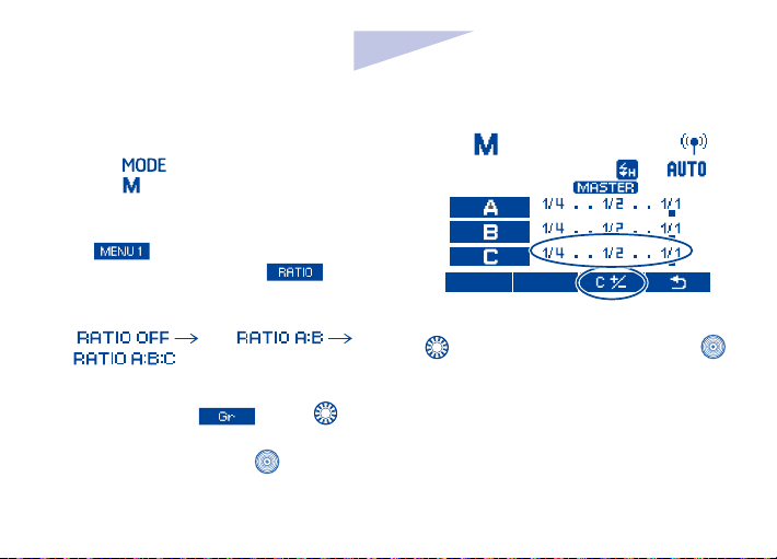
ETTL: Wireless Multiple Flash
Shooting with Flash Ratio
1. Autoash shooting with Two Slave Groups
You can divide the slave units into two
ring groups A and B, and adjust the
33

lighting balance (ash ratio). The exposure
is controlled automatically so that the total
ash output of ring group A and group B
results in the standard exposure.
1.1 Set the ring group of the slave units
Operate and set the slave unit group one
by one. Set one unit to<
>, and set the
other to < >. For the slave unit settings,
see the ash or Receiver’s instruction
manual.
1.2 Set the ratio mode: Press the master
unit’s function button 4 to display
. Press function button 2 corresponding to
to set to < >.
34

1.3 Set the ash ratio: Press function
button 3 corresponding to , and
again press the function button 3 while it is
corresponding to
set the ash ratio and press <
Press function button 4 corresponding to
to return to shooting-ready state.
, turn < > to
>button.
En
INSTRUCTION MANUAL
1.4 Take the picture: the slave unit ash at
the set ash ratio.
35

A
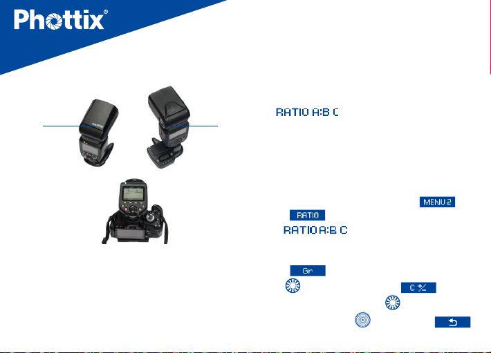
2. Autoash Shooting with Thee Slave Groups
You can add ring group C to ring groups A
and B. C is convenient to set lighting so as to
eliminate the subject’s shadow. The setting
36
method is the same as “Autoflash Shooting
with Two Slave Groups”.
At the ratio mode
A and B can be set by flash ratio. Group C
B
is independent with its flash output level
assigned by the camera.
2.1 Set a flash as firing group C: For
the slave unit settings, see the flash’s
instruction manual.
2.2 Press the master unit’s function button
4 to display . Press function button
2 corresponding to to set to <
2.3 Set flash exposure compensation as
required
>.
, group

Press function button 3 corresponding to
, turn < > and press function
button 3 corresponding to
turn <
the ash exposure compensation amount
for group C.
Press function button 4 corresponding to
> and press < > button to set
to return to shooting-ready state.
. Again
En
INSTRUCTION MANUAL
C
A:B
3. Slave Group Control
If you need more ash output or wish to
perform more sophisticated lighting, you
can increase the number of slave units.
37

Simply set an additional slave unit to the
ring group (A, B or C)whose ash output
you want to increase. You can increase the
number of slave units up to 15 units in
total.
For example, if you set a ring group with
three slave units to A, the three units are
controlled as a single ring group A with a
large ash output.
M: Wireless Multiple Flash Shooting
with Manual Flash Output
When doing multiple flash shooting with
manual flash output, you can shoot with a
dierent ash output setting for each slave unit
(firing group). Set all the parameters on the
master unit.
38
En
1.Press < > button to set the flash
mode to < >.
2.Set the number of ring group:
While
button 2 corresponding to to set
the groups to fire. The setting changes
as follows each time pressing the button:
ALL( ) A/B( ) A/
B/C( ).
3.Select a ring group: Press function button
3 corresponding to
select the group for which you want to set
the ash output, and press <
is displayed, press function
, turn< > to
> button.
INSTRUCTION MANUAL
4.Set the ash output: Press function button 3 , turn
<
>to set the ash output and press < >
button. Repeat step 3and 4 to set the output of all
groups.
5.Take the picture: Each group res at the set ash
output.
39

MULTI: Stroboscopic Flash
Stroboscopic flash is an advanced manual flash
shooting method. When using stroboscopic flash
with a slow shutter speed, you can shoot multiple
successive movements within a single picture,
similar to stop-motion pictures. In stroboscopic
flash, set the flash output, number of flashes, and
ash frequency (number of ashes per second = HZ).
40
1. Press master unit’s < >button to set
the ash mode to< >.
2. Set the number of ring groups and ash
output for each group by referring to manual
ash on the preceding page.
3. Set the flash frequency and number of
ashes:
When
is displayed, press function
button 2 corresponding to , turn

En
INSTRUCTION MANUAL
< > to set the number of ashes and press
<
>button;
Press function button 3 corresponding
to
frequency and press <
, turn < > to set the flash
>button.
Note:
1) High speed sync function is not available
when using stroboscopic ash.
2) Phottix Laso Receiver does not support
MULTI mode.
Gr: Shooting with a Dierent
Flash Mode for Each Group
When using an EOS digital camera released
since 2012, you can shoot with a dierent ash
mode set for each ring group, with up to 5
groups(A/B/C/D/E).
The ash modes that can be set are E-TTL II/
E-TTL autoash,
external ash metering. When the ash mode
or , exposure is controlled to result
is
in standard exposure for the main subject as
a single group. The function is for advanced
users.
1. Set the ash mode to <
Press < > button on master unit to set
the ash mode to < >.
2. Set the ring group on the slave units
Operate and set the slave units one by one,
and set a firing group (A/B/C/D/E) for all
Manual ash and Auto
>
41

the slave units. For slave unit settings, see
the flash or wireless Receiver’s instruction
manual.
3. Set the ash mode
Set the flash mode of each firing group by
operating the master unit.
While
is displayed, press function
button corresponding to and turn <
>to set the group.
Press function button 2 to select the flash
mode of the selected group from <
<
>and< >.
To turn off the firing of the selected group,
press function button 1 corresponding to
and set it to <OFF>.
42
Repeat step 3 to set the ash mode.
>,

En
4. Set the flash output or flash exposure
compensation amount
While a ring group is selected, press function
button 3, turn <
corresponding to the flash mode, and press
<
> button.
When using the <
flash output. When using the <
>or<
compensation amount as required.
Press function button corresponding to when
is displayed, flash exposure compensation
can be set for all groups.
Repeat step 4 to set the ash function of all
groups.
> to set the ash function
> mode, set the
>, set the ash exposure
INSTRUCTION MANUAL
43

5. Take the picture: Each slave units fires in
the ash mode set for each group.
Linked Shooting
Linked shooting is a function that automatically
releases the shutter of a slave unit camera
by linking it to a master unit camera. You can
shoot with linked shooting for up to 16 units,
including both master units and slave units.
This is convenient when you want to shoot a
subject from multiple angles at the same time.
To shoot with linked shooting, attach Phottix
Laso Transmitters to the cameras. Besides,
you can choose to use Canon Speedlites that
support radio transmission wireless shooting
44
or Canon ST-E3-RT Speedlite Transmitter.

Linked shooting setting
1. Set to linked shooting mode
Press and hold linked shooting button until
is displayed. Linked shooting
mode’s “Slave unit” is set; Press linked
shooting button again to set “Master unit” of
linked shooting mode.
En
2. Set the channel and ID
Set the channel by pressing function button
2 corresponding to
select the channel and press <
You also choose to scan the radio reception
status and set the master unit’s transmission
channel automatically or manually. For
operation please refer to preceding wireless
setting section.
Set wireless radio ID: Press function button
INSTRUCTION MANUAL
, turn < > to
>button.
45

3 corresponding to , turn < >
to select the digit to be set, and press
<
> button. Again turn < > to select
a number from 0-9, and press the < >
button. Repeat the procedure to set the 4 ID
digits one by one. Press function button 4
for corresponding to
to return to the
shooting-ready state.
3. Set the camera’s shooting functions
4. Set all the Transmitters
Repeat steps 1to3 and set all the Transmitters
to “Master unit” or “Slave unit” in the linked
shooting mode.
Set the Speedlites used in linked shooting in
the same way.
46
When pressing linked shooting button to
change the setting of a unit from “Slave unit”
to “Master Unit”, the other Transmitter (or
Speedlites) that were set to “Master Unit” until
then automatically switch to “Slave unit.
5. Set up the slave unit cameras
Check that the <
> lamp of the slave
unit lights green and place all the slave units
within master unit’s the radio transmission
range.
6. Take the pictures
Check that the <
> lamp of the master
unit lights green and take the picture.
The slave unit cameras are released in
coordination with the master unit camera.
After shooting with linked shooting, the

En
INSTRUCTION MANUAL
< > lamp of slave unit briey lights
orange.
7. Press function button 1 corresponding to
on master unit will release the shutter
of all slave unit cameras.
Noted:
1.When using the linked shooting function,
the slave unit camera might need a
shutter release cable(available separately)
depending on the camera models.
1) EOS digital cameras since 2012
(excluding EOS 1200D) do not need to
use shutter release cable.
2) EOS cameras before 2012, which are
compatible with E-TTL II/E-TTL autoash
and come with N3 type remote
terminal EOS, shutter release cable will
be needed for linked shooting.
2. Shooting with manual focus is
recommended for the slave unit cameras. If
focus cannot be achieved with autofocus,
linked shooting is not possible with the
corresponding slave unit cameras.
V. Setting Transmitter
Functions with Camera
Operations
When using EOS digital camera released
since 2007, you can set ash functions,
Transmitter functions or Custom Functions
from the camera’s menu screen. For the camera
47

operations, see the camera’s instruction
manual. (Examples displayed are EOS 6D menu
screen)
1. Phottix Laso Transmitter Function Setting
1.1 Select [External Speedlite control]
or[Flash control].
1.2 Select[Flash function settings]
or[External ash func. setting], the screen
changes to the (external) ash function
settings screen
48
1.3 Select an item and set the function. (The
setting screen varies depending on the
camera)
2.Settings Available in [Flash function
settings]

En
INSTRUCTION MANUAL
49

FEB
Wireless flash
functions
(setting)
Users can take three shots while automatically changing the flash
output, with settable range up to ±3 stops in 1/3-stop increments.
Radio transmission wireless flash shooting is set automatically.
(*For EOS digital camera released since 2012).
Clear Speedlite
function
settings
You can restore Phottix Laso Transmitter to their default settings
3. Transmitter Custom Function Settings
The displayed contents vary depending
on the camera. If C.Fn-20 and 22 are not
displayed, set them by operating the
Transmitter.
50

3.1 Select[Flash C.Fn settings]or[External
ash C.Fn setting]
3.2 Select the Custom Function number
and set function
3.3 To clear all the Custom Function
settings, select [Clear all Speedlite C.Fn’s] or
[Clear ext. ash C.Fn set] in step 1.
Note: [Auto power o] under [Flash C.Fn
settings] is corresponding to Phottix Laso
Transmitter’s C.Fn 01: Auto IDLE. You can
En
enable or disable Auto IDLE for Phottix
Laso
menu option.
INSTRUCTION MANUAL
Transmitter by operating the Camera
VI. Customizing the
Transmitter
Phottix Laso Transmitter supports Custom
function (C.Fn) and Personal Function ( P.Fn)
setting. You can customize the Transmitter
features to suit your shooting preferences with
custom functions and personal functions. Note
that the personal functions are customizable
functions unique to the Phottix Laso
Transmitter.
51

C.Fn: Setting custom functions.
1.Press function button 4 until is
displayed on the screen.
2.Press and hold the function button 1
corresponding to
Function screen is displayed.
3.Turn<
set, and press<
setting.
4.Turn<
5.Press function button 4 corresponding to
6.To restore all the default settings of
52
>to select an item(number) to
>to select the setting, and press<
> button to conrm the selection.
to return to previous state.
until Custom
>button to display the
custom function, press function button 2
corresponding to
button 1 corresponding to . To
cancel the operation, press function button 4
corresponding to .
, and press function

Custom Functions Chart
Custom
Function No.
C.Fn 01
C.Fn 02
C.Fn 03
Functions
: Auto IDLE
Modeling flash
:
FEB auto cancel
En
Setting No. Setting and descriptions
Enable Auto IDLE when the Phottix Laso Transmitter is not
operated for 5min.,
Disable Auto IDLE when the Phottix Laso Transmitter is not
operated for 5min.,
Press the camera’s depth-of-field
preview button to fire the modeling flash
Press Phottix Laso Transmitter’s test flash button to fire the
modeling flash
Press the camera’s depth-of-field preview button or Phottix Laso
Transmitter’s test flash button to fire the modeling flash
Disable the modeling flash
Enable: Set to automatically cancel FEB after shooting three shots
with FEB
Disable: Set not to automatically cancel FEB after shooting three
shots with FEB
INSTRUCTION MANUAL
53

54

P.Fn: Setting personal functions
1. When Custom Function screen is displayed,
press function button 1 corresponding to
to display Personal Function screen.
2. Set the personal function in the same way
as step 3 and 4 for the custom function.
3. To restore all the default setting of personal
En
function, set it in the same way as step 6 for
custom function.
INSTRUCTION MANUAL
55

Personal Functions Chart
Personal
Function No.
P.Fn 01
P.Fn 03
P.Fn 04
P.Fn 08
56
Functions
: LCD panel
display contrast
: LCD
panel illumination
color: Master
: LCD
panel illumination
color: Slave
: AF assist
beam
Setting No. Setting and descriptions
You can adjust the contrast of the LCD panel in 5 levels.
When the Phottix Laso Transmitter is set as master unit(radio
transmission wireless shooting, linked shooting), select green as
color of the LCD panel illumination.
When the Phottix Laso Transmitter is set as master unit(radio
transmission wireless shooting, linked shooting), select orange as
color of the LCD panel illumination.
When the Phottix Laso Transmitter is set as slave unit(linked
shooting), select orange as color of the LCD panel illumination.
When the Phottix Laso Transmitter is set as slave unit(linked
shooting), select green as color of the LCD panel illumination.
Enable the AF assist beam
Disable the AF assist beam

En
INSTRUCTION MANUAL
Upgrading rmware by USB
The rmware of the Phottix Laso Transmitter
can be upgraded using the included USB
cable. Any upgrades and full instructions will
be announced on the Phottix Blog
(journal.phottix.com).
VII. Trouble Shooting Guide
1. Power does not turn on
1.1 Make sure the batteries are installed in
correct orientation.
1.2 Check battery contacts are in good
contact and that the batteries are sucient
with power.
2.The Slave unit doesn’t re
2.1 Check if the slave unit supports radio
transmission wireless ash
2.2 Set the slave unit to <
2.3 Set the transmission channels and
wireless radio IDs of the master unit and
slave unit to the same numbers.
2.4 Check if the slave unit is within the
transmission range of the master unit.
2.5 If using Phottix Laso
refer to the Receiver’s manual instruction
to check the operation.
3. <
Set the shutter speed 1 stop slower than the
ash sync speed.
>is displayed
>< >.
Receiver, please
57

VIII. Technical Specication
58

En
INSTRUCTION MANUAL
59

Please note: Product specications and external design are subject to change without further
notice.
60

En
Accessory List
Phottix Laso Transmitter 1 PC
Bag 1PC
AA Battery 2 PCS
USB Cable 1 PC
Manual 1 PC
Firmware Notice Card
Warranty Card 1 PC
QC Certicate 1 PC
*Please check the package according to the accessory list.
1 PC
INSTRUCTION MANUAL
61

该产品属于 Class 3R 级激光产品,根据下
列标准 IEC 60825-1/GB 7247.1 “激光产
品的辐射安全”。
Class 3R: 该等级的激光不直接观测时是安
全的。该等级的激光可能超出 MPE,但一般
不会造成伤害。该等级的可见光连续波激光
器功率不能超过 5mW。
62

Cn
Simp
说明书
感谢您购买 Phottix 产品
在使用 Phottix Laso 无线引闪器 For
注意:
Canon 前,请务必通读本使用说明书和相机
及闪光灯等相关设备的使用方法,以保证您
熟悉操作,正确使用。
无线引闪器 For Canon/ 发射器
Phottix Laso 发射器是无线闪光拍摄用信号
发射器,最多可以控制 5 个从属组(15 个单
元)具有使用无线电传输进行无线多重闪光
拍摄功能的闪光灯。此外,还可以通过搭配
Phottix Laso 接收器,控制非无线模式下的
多款佳能 ETTL 闪光灯。本产品支持 E-TTL Ⅱ /
E-TTL 自动闪光、手动闪光、频闪闪光、自
动外部闪光测光等多种闪光模式以及联动拍
摄,可以满足多样化的布光需求。
安全须知
1. 本产品属精密电子仪器,请注意防潮防尘。
2. 安装本产品时请务必关闭所有装置电源。
3. 请勿摔落或碰撞本产品。
4. 请勿在易爆易燃或高温环境中使用本产品。
5. 请勿用化学或有机溶剂清洁机身 , 请用柔
软干净的布或镜头纸对其外表面进行擦拭。
6. 长时间不使用引闪器时,请将电源关闭并
将电池取出。
7. 干扰:Phottix Laso 无线引闪器以 2.4GHz
传送无线电信号。它的执行将会受到电流,
磁场和无线电信号、无线路由器、移动电话
以及其他电子设备的影响,还会受诸如大型
建筑或墙壁,大树,栅栏或汽车等周边事物
63

的影响。如果您的引闪器不能被触发,请稍
微移动它的位置。
依据低功率电波辐射性电机管理办
法:
第十二条经形式认证合格之低功率射频电机,
非经许可,公司、商号或用户均不得擅自变
更频率,加大功率或变更原设计之特性及功
能。
第十四条低功率射频电机之使用不得影响飞
航安全及干扰合法通信:经发现有干扰现象
时,应立即停用,并改善至无干扰时方得继
续使用。
前项合法通信,指依电信规定作业之无线电
信。低功率射频电机须忍受合法通信或工业、
64
科学及医疗用电波辐射性电机设备之干扰。

目 录
一 . 部件名
二 . 使用前准备
三 . 液晶屏显示内容
四 . 无线闪光拍摄:无线电传输
-----------------------------------------------------------------------------67
------------------------------------------------------------------------69
-------------------------------------------------------------------75
------------------------------------------------ -------79
1. 无线设置
2. ETTL:全自动无线闪光拍摄
3. 使用全自动无线闪光
4. ETTL:使用闪光光比的无线多重闪光拍摄
5. M:使用手动闪光输出的无线多重闪光拍摄
6. MULTI:频闪闪光
------------------------------------------------------------------------80
----------------------------------------------------84
------------------------------------------------------------85
--------------------------------------------------------------95
Simp
Cn
--------------------------------------90
-------------------------------------93
说明书
65

7. Gr:为各组设定不同的闪光模式进行拍摄
8. 联动拍摄
------------------------------------------------------------------------99
五 . 相机操作设定无线引闪器功能
六 . 自定义信号发生器
1. C.Fn:设定自定义功能
2. P.Fn:设定个性化功能
七 . 故障诊断
八 . 规格参数
66
-------------------------------------------------------------------------- 112
-------------------------------------------------------------------------- 113
-----------------------------------------------------------------106
---------------------------------------------------------106
--------------------------------------------------------- 110
--------------------------------------- 96
------------------------------------------------------102

一 . 部件名称
1
1.<LINK> 指示灯 : 无线电传输确认指示灯
2. 液晶显示屏
3. 功能按钮 1
4. 功能按钮 2
5. 功能按钮 3
6. <MODE>:闪光模式按钮;
7. <
>:充电指示灯 / 测试闪光按钮
8. <
9. <
10. 固定座锁定杆
11. 电池仓
12. 功能按钮 4
13. <
>:选择 / 设置按钮
>: 选择拨盘
>:联动拍摄按钮
Cn
Simp
说明书
2
4
5
3
6
7
8
9
11
12
13
14
15
10
67

14. 电源按钮
15. 闪光曝光确认指示灯
16. 锁定释放按钮
17. USB 端口
18. 遥控释放端子
19. 电子触点
20. 固定座
21. 锁定销
22. 自动对焦辅助灯
68
19
20
16
17
18
21
22

二 . 使用前准备
装入电池
1. 按住 Phottix Laso 发射器电池盖 , 依所示
方向打开电池盖。(如图一)
Cn
Simp
说明书
图一
2. 按图所示插入 AA 电池,注意确保电池
的 +/- 朝向正确(注:请使用两节 AA 型
碱性电池或 AA 型镍氢电池)。(如图二)
3. 放回电池盖,并往后推至锁紧的位置。
图二
69

安装与拆卸
将 Phottix Laso 发射器安装到相机上
1. 关闭相机和 Phottix Laso 发射器。
2. 将 Phottix Laso 发射器热靴与相机热靴
对准。
3. 滑动 Phottix Laso 发射器使其完全插入
相机热靴。
4. 滑动锁定杆到右侧直至发出咔哒声将
Phottix Laso 发射器锁定到位。(如图三)
图三
70
取下 Phottix Laso 发射器
1. 锁定释放:按住锁定杆上的锁定释放按
钮的同时将锁定杆滑动到最左侧。(如图四)
2. 将 Phottix Laso 发射器滑出相机热靴
图四
开启 / 关闭 Phottix Laso 发射器
1. 开启:长按电源按钮直至菜单界面出现
在液晶屏上。

Cn
Simp
说明书
2. 关闭:长按电源按钮直至液晶屏上无显
示。
注意:如出现低电量显示
换电池。
,请及时更
在 Phottix Laso 发射器上查询版本
信息
可以在 Phottix Laso 发射器查询当前的版本
信息 : 长按“电源按钮”开启 Phottix Laso
发射器的同时按下“< > 按钮”直至
液晶屏上显示版本信息。
< > 充电指示灯 / 测试闪光按钮
1. 当无线拍摄(从属)就绪时,充电指示
灯点亮
2. 无线拍摄期间,当所有闪光灯回电完毕
时,主控单元充电指示灯点亮
3. 无线拍摄期间,按此按钮将可以进行测
试闪光
从从属单元进行遥控释放
在无线拍摄期间,Phottix Laso 发射器支
持从从属单元进行遥控释放,可以从设为从
属单元的闪光灯或 Phottix Laso 接收器进
行遥控释放(遥控拍摄)。有关操作,请参
见闪光灯或 Phottix Laso 接收器的使用说
明书。
当使用此功能拍摄时,根据相机的不同,可
能需要“快门线”(另售)。
1. 除 EOS 1200D 外,对于 2012 年以后
发售的 EOS 数码相机,不需要“快门线”。
71

2. 对于上述以外的兼容 E-TTL II/E-TTL
自动闪光并具有 N3 型遥控端子的 EOS
相机,则需要“快门线”(另售)才能
从从属单元进行遥控释放。
从从属单元进行测试闪光
在无线拍摄期间可以从设为从属单元的闪光
灯进行测试闪光。有关操作,请参见闪光灯
的使用说明书。
当两个或两个以上单元设为主控时,
注意:
> 指示灯以亮绿灯的主控单元进行
<
闪光。
造型闪光功能
1. 从主控单元进行造型闪光
72
当按相机的景深预视按钮时,闪光灯连续闪
光 1 秒钟。此功能称为造型闪光。该功能
使您能够查看被摄体上的闪光灯光影效果
及照明平衡。此外,按 Phottix Laso 发射
器测试闪光按钮触发造型闪光(需在自定义
功能 C.Fn 02 预先设定)。
2. 从从属单元进行造型闪光
使用 2012 年开始发售的EOS 数码相机时,
可以从从属单元的闪光灯进行造型闪光。有
关操作,请参考闪光灯的使用说明书。
自动对焦辅助灯
在低照度 / 低对比度的条件下,Phottix
Laso 发射器内置的自动对焦辅助灯会自动点
亮来辅助自动对焦。发射器前面的自动对焦
辅助灯将会在被摄体上投射一个聚焦目标。

Cn
Simp
说明书
且此对焦辅助灯为激光灯,定向性好,衰减少 ,
效果显著。自动对焦灯功能可以设置为开启
或关闭(在个性化功能 P. Fn 08 中设置)。
拍摄时请尽量避免对着人眼, 以防伤害眼睛。
采用小于 5mW 的安全激光灯。
警告:
存储功能
Phottix Laso 发射器具有存储功能,可以保
存无线设置并在日后调出该设置
1. 按功能按钮 4 直至液晶屏显示
2. 保存或加载设置
按
储在内存中)。按
钮 2,保存的设置被设定。
对应的功能按钮 3,接着按
对应的功能按钮 1,设置被保存(存
对应的功能按
。
清除 Phottix Laso 发射器设置
可以将 Phottix Laso 发射器设置恢复为其默
认设置,同时按功能按钮 2 和 3 约 2s 后,
Phottix Laso 发射器设置被清除,拍摄模式
恢复为 <ETTL> 闪光模式。即使清除设置后,
传输频道、无线电 ID、C.Fn 和 P.Fn 设置也
不会被取消。
73

MENU 功能介绍
1
2
3
4
5
6
7
8
74
闪光包围曝光步长
闪光曝光补偿
自定义功能
闪光光比
扫描功能
无线电ID
传输频道
记忆功能
可以在±3EV进行调节(以1/3档为增量)
可以在±3EV进行调节(以1/3档为增量)
可以在C.Fn 01~22、P.Fn 01~08间进行设置
RATIO A:B C
ETTL
M/Multi
可以扫描无线电接收状态并自动或手动设定主控单元的传输频道
可以在0000
Ch.1
RATIO A:B
RATIO OFF
RATIO A:B:C
RATIO A:B
RATIO OFF
~9999中设置
~Ch.15 、Auto
保存当前设置
载入已存储的设置
返回拍摄就绪状态
A:B比率比值:
8:1~1:8,
以1/2档为增量

Cn
Simp
说明书
9
10
11
12
同步模式
闪光组
频闪闪光频率
频闪闪光次数
无显示
最多五组A、B、C、D、E(Gr模式下)
可在1~500Hz设置
可在1~100次设置,根据频率和闪光输出量对应输出次数
三 . 液晶显示屏显示
Phottix Laso 发射器显示屏共有五种显示模
式,即 ETTL、M、MULTI、Gr 和 LINKED
SHOT。可以通过 MODE 键在“ETTL、M、
MULTI、Gr”四种模式下进行切换,还可以
长按联动拍摄按钮,进入 LINKED SHOT 模
开启高速同步
前帘同步
式,不同的模式设置将实现不同的功能,五
种模式的界面分别如下:
75

1. ETTL/ETTL II 自动闪光模式显示:
E-TTLⅡ/E-TTL自动闪光
: 闪光曝光补偿,
闪光曝光补偿量
RATIO:共有
三种闪光组数
量可供选择:
RATIO OFF,
RATIO A:B,
RATIO A:B C
闪光组
76
: 同步
速度警告
闪光光比
:闪光包
围曝光,闪光
包围曝光步长
闪光曝光水平
:高速同步;
:提示音
: 无线电传输和
无线拍摄
: CH,频道;
AUTO,频道自动
设置
: 自定义功能
:个性化功能
:主控单元
: 从属闪光灯
就绪

Cn
Simp
说明书
2. M 手动闪光模式显示:
M: 手动闪光 手动闪光输出
3. Multi 闪光模式显示:
MULTI: 多重(频闪)闪光
闪光频率
闪光次数
77

4.Gr 组闪光模式显示 5. LINKED SHOT 模式显示:
Gr: 组闪光
三种闪光模式可选:ETTL、M、Ext.A
78
:SLAVE,从属单元;
MASTER,主控单元;
LINKED SHOT:
联动拍摄

注意:
1). 显示屏只显示当前应用的设置。
2). 在功能按钮 1 至 4 上方显示的功能(如
和
生变化。
3). 当操作按钮或拨盘时,液晶显示屏点
亮。
, )根据设置的状态发
四 . 无线闪光拍摄:无线电传
输
安装在相机上的 Phottix Laso 发射器
注意:
称为主控单元,受无线控制的闪光灯称为从
属单元。
Simp
Cn
无线闪光拍摄
使用兼容无线电传输拍摄的 Phottix Laso 发
射器和佳能闪光灯,可按照与普通 E-TTL Ⅱ /
E-TTL 自动闪光拍摄同样的方法,轻松利用
高级无线多重闪光照明进行拍摄。
安装在相机上的 Phottix Laso 发射器(主控)
的设置会自动反应在受无线控制的闪光灯(从
属)上,因此,在拍摄期间不需要操作从属
单元。只要将主控单元设定为 <
可以进行无线 E-TTL Ⅱ /E-TTL 自动闪光拍
摄。
用户可以根据个人拍摄需要使用单个从属单
元进行自动闪光拍摄,或同时使用多个从属
单元(最多 15 个)进行无线多重闪光拍摄。
除了可以将兼容无线电传输拍摄佳能闪光灯
设为从属单元,对于不具有无线电从属功能
说明书
>就
79

的佳能 ETTL 闪光灯可以和 Phottix Laso 接
收器搭配使用,实现无线闪光拍摄。
主控
Phottix Laso
发射器
从属
具有无线电从属功能的佳能闪光灯,
例600EX-RT (从属模式)
Phottix Laso接收器+佳能ETTL闪
光灯(普通模式)
注意:
1) 使用 Phottix Laso 接收器的从属单元,在
部分功能会受到限制,相关操作也会有所差
异,请参见 Phottix Laso 接收器的使用说明。
2) 当进行无线电传输无线闪光拍摄时,取决
于使用的相机,闪光模式、最高闪光同步速
度(下简称“闪光同步速度”)和高速同步
功能可能会受到限制。
80
无线设置
要进行无线拍摄,用下列步骤设定 Phottix
Laso 发射器(主控单元)和闪光灯(从属单
元)。
1. 主控单元设置:检查是否显示
。
2. 从属单元设置:有关从属单元设置,请
参见闪光灯或 Phottix Laso 接收器使用说
明书。
3. 传输频道 / 无线电 ID 设置:为了避免干
扰其他摄影师所使用的无线电传输无线多
重闪光系统或使用无线电波(无线)的其
他设备,可以改变传输频道和无线电 ID,
为主控单元和从属单元设定相同的频道和
ID。
使用下列步骤设定主控单元的传输频道和

Cn
Simp
说明书
无线电 ID,有关从属单元设置,请参见闪
光灯或Phottix Laso 接收器的使用说明书。
3.1 按功能按钮 4 直至液晶屏显示
。
3.2 设定频道: 按
按钮 1,转动 <
对应的功能
> 选择“AUTO”
或从频道 1 至 15 中选择频道,然后按
> 按钮完成设定。
<
3.3 设定无线电 ID: 按
功能按钮 2,转动 <
的位置(位数)并按 <
转动 <
<
> 从 0 至 9 中 选 择数 字 并 按
> 按钮完成单个位数的设定。
对应的
> 选择要设定
> 按钮,
3.4 重复步骤 3.3 逐一设定 4 位数,最后
按
对应的功能按钮 4 以返回拍摄
就绪状态。
81

3.5 当主控单元和从属单元之间建立传输
时,< > 指示灯以绿色点亮。
4. 扫描要设定的主控单元传输频道
Phottix Laso 发射器可以扫描无线电接收
状态,并自动或手动设定主控单元的传输频
道。当频道设为“AUTO”时,会自动设定
接收信号的频道。当手动设定频道时,可以
在参考扫描结果的同时重新设定传输频道。
4.1 在设为“AUTO”期间扫描(如图):
按功能按钮 4 直至液晶屏显示
按 对应的功能按钮 3,频道被自
82
,
动重设为信号接收良好的频道。
4.2 在频道设为 1 至15 期间扫描(如图):
按功能按钮 4 直至液晶屏显示
,

Cn
Simp
说明书
按 . 对应的功能按钮 3,以图表显示无线电接收状态,图表中的频道峰值越高,
无线电接收信号越强。
转动 <
> 从频道 1 至 15 中手动选择频道,按 <
> 按钮设定频道并返回拍摄就
绪状态。
<
> 指示灯的颜色根据主控单元和从属单元的状态发生变化。
注意:
1). 如果主控单元和从属单元的传输频道不同,从属单元不闪光。将两者设为相同的号码
或均设为“AUTO”。
83

2). 如果主控单元和从属单元的无线电 ID
不同,从属单元不闪光。
ETTL:全自动无线闪光拍摄
使用安装在相机上的Phottix Laso 发射器(主
控)和受无线控制的闪光灯(从属)时的基
本全自动无线拍摄。
1. 使用一个从属单元的自动闪光拍摄
1.1 将闪光灯设为从属单元:有关从属单
元设置,请参见闪光灯或 Phottix Laso
接收器的使用说明书。将闪光组设为 A、
B 或 C,如果设为 D 或 E,闪光灯不会闪光。
1.2 检查频道和 ID: 如果主控单元和从
属单元的频道和 ID 不同,将其设为相同
的号码。
84
1.3 定位相机和闪光灯: 相机和闪光灯
之间的距离不要超过无线电传输距离。
1.4 将闪光模式设为 <
单元上的 <
置为 <
拍摄期间,从属闪光灯自动设为 <
>。如从属单元使用 Phottix Laso接收器,
接收器上的闪光灯无需设为从属模式,
但必须将手动闪光灯设置成 ETTL 模式。
1.5 检查传输状态和闪光灯是否已就绪:
检查 <
当设为无线电从属模式的从属闪光灯
就绪时,其自动对焦辅助光发射器以
1 秒间隔闪烁;
检查主控单元液晶显示屏上的 <
> 按钮并将闪光模式设
>,在经由主控单元控制的
> 指示灯以绿色点亮;
>:按主控
>

Cn
Simp
说明书
从属闪光灯就绪图标是否点亮;
当所有闪光灯单元的回电完毕时,主
控单元的充电指示灯点亮。
1.6 检查操作:按主控单元的测试闪光按
钮(充电指示灯),从属单元闪光,如
果从属单元不闪光,检查是否将其放置
在操作范围内。
1.7 拍摄照片:按照与使用普通闪光拍摄
相同的方法设定相机并拍摄照片。如果
获得了标准的闪光曝光,闪光曝光确认
指示灯将点亮(蓝色)2 秒。
2. 使用多个从属单元的自动闪光拍摄
当需要更大的闪光输出或想要更加轻松地
进行照明时,可以增加从属单元的数量并将
其作为单个闪光灯闪光。要添加从属单元,
使用与“使用一个从属单元的自动闪光拍
摄”相同的步骤。将闪光组设为 A、B 或 C,
如果设为 D 或 E,闪光灯不会闪光。当增
加了从属单元的数量时,执行自动控制以使
所有闪光灯以相同的闪光输出闪光并确保
总闪光输出能够达到标准曝光。
使用全自动无线闪光
在 Phottix Laso 发射器(主控单元)上设定
的闪光曝光补偿和其他设置也会在闪光灯(从
属单元)中自动设定,不需要操作从属单元。
85

1. 闪光曝光补偿
可以像设定普通曝光补偿一样设定闪光曝
光补偿。可以在 ±3 档间以 1/3 档为增量设
定闪光曝光补偿量。设置方法如下:
1.1 按功能按钮 4 直至液晶屏显示
。
1.2 按
屏显示
突出显示。
1.3 设定闪光曝光补偿量 : 转动 <
设定闪光曝光补偿量并按下 <
对应的功能按钮 2,液晶
图标并且闪光曝光补偿量被
>
> 完
成设定。
1.4 “0.3”表示 1/3 档,“0.7”表示 2/3档。
要取消闪光曝光补偿,将补偿量设
1.5
回到“±0”
86

Cn
注意:
1) 闪光曝光补偿量可以直接转动 <
> 进行设定,无需操作功能按钮 2。此操
作需在自定义功能 C.Fn13 预先设定。 .
2)如相机的曝光补偿设定为 1/2 档增量,
将以 1/2 档为增量设定最大 ±3 的闪光曝
光补偿。
2. 闪光包围曝光
可以在自动改变闪光输出的同时拍摄三张
照片,这称为 FEB(闪光包围曝光)。以
1/3 档为增量,可设置的范围最大为 ±3 档。
设置方法如下:
Simp
说明书
87

2.1 按功能按钮 4 直至液晶屏显示
。
2.2 按
屏显示
对应的功能按钮 3,液晶
并且 FEB 水平显示被突出
显示。
2.3 设定 FEB 水平: 转动 <
FEB 水平,并按下 <
> 完成设定。
2.4 “0.3”表示 1/3 档,“0.7”表示 2/3 档。
2.5 当与闪光曝光补偿配合使用时,根据
闪光曝光补偿量进行 FEB 拍摄。
注意:
1) 可以在自定义功能 C.Fn03 设定,拍
摄三张照片后,是否自动取消 FEB。
88
> 设定
2) 可以在自定义功能 C.Fn04 中,根据
个人需要设定 FEB 拍摄顺序。
3. 高速同步
使用高速同步功能,可以在所有快门速度下
同步闪光。高速同步在想要使用光圈优先自
动曝光对人像被摄体进行填充闪光时较为
方便。只有从 2012 年开始发售的 EOS 数
码相机可以利用高速同步。设置方法如下:

3.1 按功能按钮 4 直至液晶屏显示
。
3.2 按
屏上显示
再次按
3.3
即可关闭
对应的功能按钮 2,液晶
。
对应的功能按钮 2,
.
4. 闪光曝光锁
使用 FE(闪光曝光)锁,您可以为场景的
Cn
Simp
说明书
各个部分锁定正确的闪光曝光设置。通过操
作相机执行闪光曝光锁。有关操作,请参见
相机和闪光灯的使用说明书。
5. 关于主控单元
可以使用两个或以上主控单元(主控单元
+ 从属单元 = 最多 16 个单元)。通过准备
多台装有主控单元的相机,可以在保持相
同照明(从属单元)期间更换相机进行拍
摄。请注意当使用两个或以上主控单元时,
<
> 指示灯的颜色根据打开电源的顺
序而有所不同。第一个主控(主主控)为绿
色,第二个和之后的主控(副主控)为橙色。
89

ETTL:使用闪光光比的无线多重闪
光拍摄
1. 用两个从属组进行自动闪光拍摄
可以将从属单元分成两个闪光组 A 和 B 并
调整拍摄用照明平衡(闪光光比)。自动控
制曝光以使闪光组 A 和 B 的总闪光输出达
到标准曝光。闪光比设定方法如下:
1.1 逐一操作和设定从属单元,将一个单
元设为 <
关从属单元设置,请参见闪光灯的使用
说明书。
1.2 设定主控单元闪光比模式:按主控
单元的功能按钮 4 以显示
按 对应的功能按钮 2 并设为
< >;
90
>,将另一个设为 <
>。有
;

1.3 设定闪光光比:按 对应的功
能按钮 3,再次按下此时对应 的
功能按钮 3,转动 <
并按 <
> 按钮,按
> 设定闪光光比
对应的
功能按钮 4 以返回拍摄就绪状态。
Cn
Simp
说明书
光。
91
1.4 拍照时从属单元以设定的闪光光比闪
A B
2. 用三个从属组进行自动闪光拍摄(如图)
可以将闪光组 C 添加到闪光组 A 和 B,C,
即可在改变闪光光比(倍数)的同时进行
E-TTL Ⅱ /E-TTL 自动闪光拍摄,有助于设
定照明以消除被摄体的阴影。基本设定方法
92
与“用两个从属组进行自动闪光拍摄”相同。
在
的闪光输出可以通过闪光比进行设置。C 组
是独立设置的,它的闪光输出由相机决定。
2.1 将闪光灯设为闪光组 C:有关从属单
元设置,请参见闪光灯的使用说明书。
2.2设定主控单元闪光比模式:按主控
单元的功能按钮4以显示 ;
按 对 应 的 功 能 按 钮 2 并 设 为
< >。
2.3 根据需要设定闪光曝光补偿:
按
< > 并选择 C 组;按 . 对应
的功能按钮 3,转动 <
光补偿量并按 <
闪光比模式下 A 组和 B 组
对应的功能按钮3,转动
> 设定闪光曝
> 按钮;按

Cn
Simp
说明书
的功能按钮 4 以返回拍摄就绪状态。
C
3. 从属组控制
如果需要更大的闪光输出或希望进行更
完善的照明,可以增加从属单元数量。
只需在想要增加闪光输出的闪光组(A、
A:B
B 或 C)中设定更多的从属单元。可以将
从属单元数量增加到最多 15 个单元。例
如,如果将具有 3 个从属单元的闪光组
设为 <
输出的单个闪光组 A 控制。
>,3 个单元被作为具有较大闪光
M:使用手动闪光输出的无线多重
闪光拍摄
使用手动闪光的无线(多重闪光)拍摄,可
以为每个从属单元(闪光组)设定不同的闪
光输出进行拍摄,在主控单元上设定所有操
作。
93

1. 按 键将闪光模式设为 < >
2. 在显示
期间,按
对
应的功能按钮 2,并设定要闪光组数
量 。 每次 按 该 按钮 , 设 置变 化 如 下:
ALL
(
) A/B( )
A/B/C( ).
3. 按
对应的功能按钮3,转动
< > 选择想要设定闪光输出的组并按
> 按钮。
<
94

Cn
Simp
说明书
4. 按功能按钮 3,转动 <
出并按 <
所有组设定闪光输出。
5. 拍照时各组以设定的闪光输出闪光。
> 按钮,重复步骤 3 和 4 为
> 设定闪光输
MULTI: 频闪闪光
频闪闪光是高级手动闪光拍摄方法。以慢速
快门使用频闪闪光时,可以在一张照片上拍
摄类似于逐格拍摄动画的多个连贯动作。在
频闪闪光模式下,设定闪光输出、闪光次数
和闪光频率(每秒的闪光次数 =Hz)。
95

1.按主控单元上的 < > 按钮并设为
< >。
2. 参照手动闪光步骤 2,3 和 4,设定闪光组
数量和各组的闪光输出。
3. 在显示 期间,按 对应的
功能按钮 2,转动 <
并按 <
4. 按
<
注意:
1. 频闪闪光期间不能使用高速同步。
2. Phottix Laso 接收器不支持此闪光模
式。
96
> 按钮
对应的功能按钮3,转动
> 设定闪光频率并按 <
> 并设定闪光次数
> 按钮。
Gr:为各组设定不同的闪光
模式进行拍摄
当使用从 2012 年开始发售的 EOS 数码相机
时,可以为各闪光组(最多五个组(A/B/C/
D/E))设定不同的闪光模式进行拍摄。可以
设定的闪光模式为
闪光、
光。当闪光模式为
组控制曝光以获得主被摄体的标准曝光。此
功能面向对照明非常熟知和有经验的高级用
户。
1. 将闪光模式设为 <
按主控单元上的 <
式设为 < >。
E-TTL Ⅱ /E-TTL 自动
手动闪光和 自动外部闪光测
或 时,作为单个
>。
> 按钮并将闪光模

2. 在从属单元上设定闪光组
逐一操作和设定从属单元,为所有的从属单
元设定闪光组(A/B/C/D/E),有关从属
单元设置,请参见闪光灯 / 接受器的使用说
明书。
3. 设定闪光模式
通过操作主控单元设定各闪光组的闪光模
式。在显示
的功能按钮3 并转动 <
按功能按钮 2 并从 <
期间,按 对应
>以选中闪光组。
>、< >
和< > 中选择所选组的闪光模式。
要关闭所选组的闪光,按
对应的
功能按钮 1 将其设为 <OFF>。重复步骤 3
设定所有组的闪光模式。
Cn
Simp
说明书
97

4. 设定闪光输出或闪光曝光补偿量
在选择了闪光组期间,按功能按钮3,转
> 根据闪光模式设定闪光功能并
动<
按 <
> 按钮。当使用 <
时,设定闪光输出,当使用 <
<
> 模式时,根据需要设定闪光曝
光补偿量。
如果在显示
时按 对应的功
能按钮 2,可以为所有闪光组设定设定闪光
曝光补偿。重复步骤 4 设定所有组的闪光
功能。
98
> 模式
>或

5. 拍摄照片
各从属单元按照为各组设定的闪光模式闪
光。
联动拍摄
联动拍摄是通过将从属单元相机链接到主控
单元相机,从而自动释放从属单元相机快门
的功能,可以对包括主控单元和从属单元在
内的最多 16 个单元使用联动拍摄进行拍摄。
想要同时从多个角度拍摄同一个被摄体,该
功能较为方便。要使用联动拍摄进行拍摄时,
在相机上分别安装 Phottix Laso 发射器,此
外,还可以选用支持无线电传输无线拍摄的
佳能闪光灯或 ST-E3-RT 信号发射器。
Simp
Cn
1. 设为联动拍摄模式
长按联动拍摄按钮直到液晶屏上显示
已设定,再次按联动拍摄按钮便可以将联动
说明书
,联动拍摄模式的“从属单元”
99

拍摄模式设定为“主控单元”。
2. 设定频道和 ID
按
对应的功能按钮 2,并转动 <
> 设定频道,按 < > 按钮完成设定。
(Phottix Laso 发射器可以扫描无线电接收
状态,并自动或手动设定主控单元的传输频
道,具体操作请参照上文无线设置 )。
100
按
> 并按 <
数,转动 <
位数,转动 <
<
定四个 ID 位数,按
对应的功能按钮 3,转动 <
> 按钮选择需要设定的 ID 位
> 按钮选择需要设定的 ID
> 进行 ID 设置,最后按
> 按钮完成设定。重复此操作逐一设
对应的功能按
钮 4 返回拍摄就绪状态。
 Loading...