

Page 1
En
INSTRUCTION MANUAL
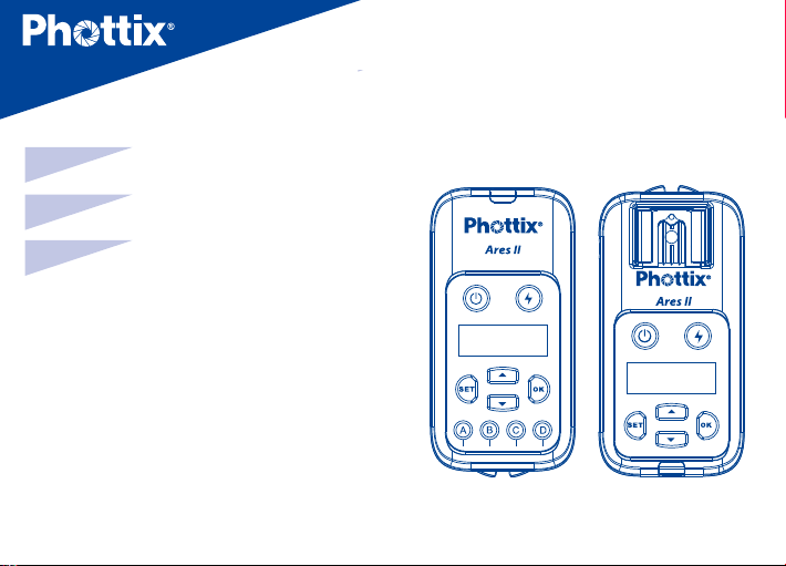
Phottix Ares II Flash Trigger
En
Cn
Cn
Simp
Trad
INSTRUCTION MANUAL 2
说明书 17
說明書 28
1
Page 2

Thank you for purchasing a
Phottix product
Caution: Before using the Ares II Flash Trigger
please read these instruction carefully. Consult
the manual of your camera and ash for setting
specic functions.
The Ares II system consists of transmitter and
receiver and is designed to work in Manual
Exposure mode with the ash and camera and
has no TTL functions.
Compatibility with existing
Phottix Products
1. Ares II is compatible with Strato II system
when using Channels 1-4 channels,as long
2
as the transmitter and receiver are set to the
same channel and group
The Ares II Transmitter can trigger Strato
•
II receiver, Mitros+ in Strato II RX mode, and
Indra500/Indra360 studio light in Strato II
RX mode under the above conditions.
The Ares II Receiver can be triggered
•
by Strato II transmitter,Odin, Odin II
transmitter(Channels 1-4 only) and Mitros+
in Odin TX mode(Canon or Sony only)
2. The Ares II is not compatible with other
Phottix product when using channels 5-16.
Only Ares II Transmitters and Receivers can be
used when using channels 5-16
:
Page 3

En
INSTRUCTION MANUAL
What is in the box:
Transmitter and receiver set:
1. Transmitter unit – 1pc
2. Receiver unit – 1pc
3. Carrying bag – 1pc
4. Phottix 3.5 (male) to 3.5 mm (male) Sync
Cord (40cm)– 1pc
5. 3.5mm (female) to 6.3mm (male)
adapter – 1pc
6. Hand lanyard – 2pcs
7. User manual – 1pc
8. Warranty card – 1pc
Transmitter only
1. Transmitter unit – 1pc
2. User manual – 1pc
3. Hand lanyard – 1pc
4. Warranty card
Receiver only
1. Receiver unit – 1pc
2. User manual – 1pc
3. Phottix 3.5 (male) to 3.5 mm (male) Sync
Cord (40cm)– 1pc
4. 3.5mm (female) to 6.3mm (male)
adapter – 1pc
5. Hand lanyard – 1pc
6. Warranty card
3
Page 4
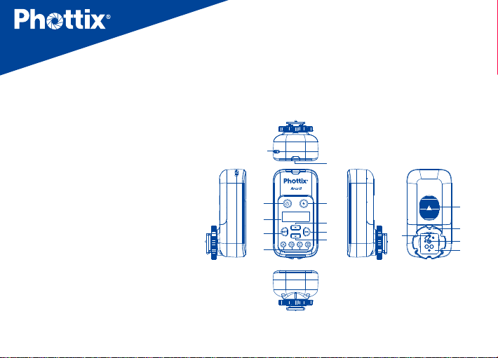
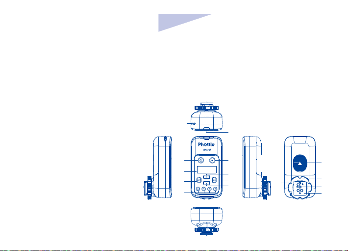
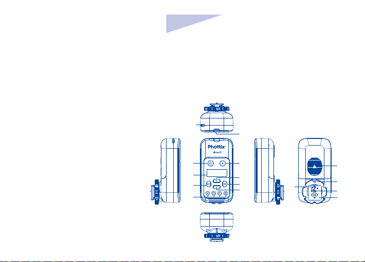
Parts
Transmitter
1. Power button
2. LCD display
3. Settings button
4. Group selection buttons (From
left to right is A,B,C,D)
5. Test button
6. Selection button Up
7. OK/conrm button
8. Selection button Down
9. LED status light
10. Lanyard attachment
11. Battery compartment cover
12. Locking ring
13. Hot shoe contact
14. Hot shoe
15. Locking Pin
4
10
1 5
2
3
4
9
11
6
7
8
15
12
13
14
Page 5
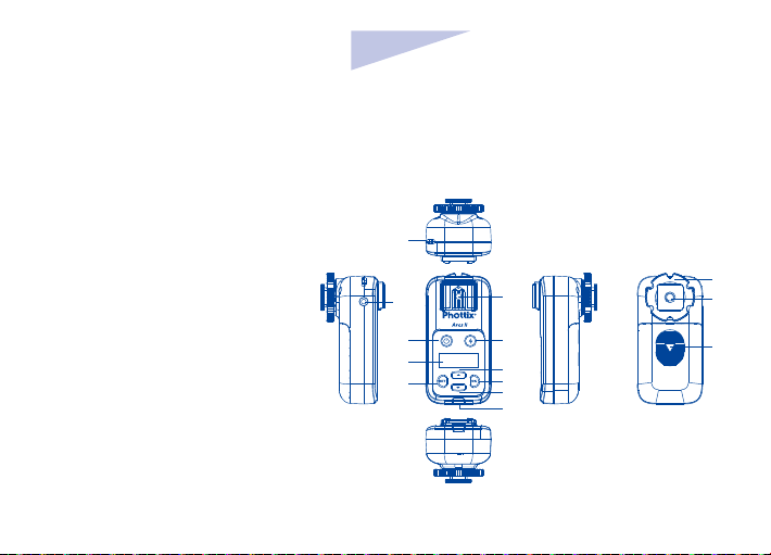
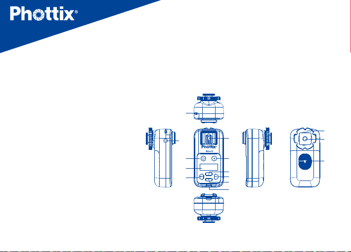
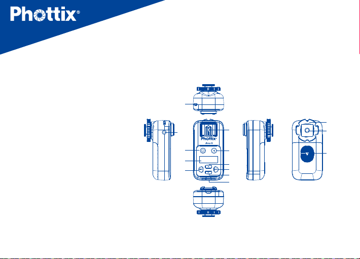
Receiver
1. Power button
2. LCD display
3. Settings button
4. hot shoe mount
5. Test button
6. Selection button Up
7. OK/Conrm button
8. Selection button Down
9. LED status light
10. Lanyard attachment
11. Locking Ring
12. Coldshoe/ ¼”x20 threaded lug
13. Battery compartment cover
14. 3.5mm sync port
En
INSTRUCTION MANUAL
10
14
1
2
3
4 12
5
6
7
8
9
11
13
5
Page 6
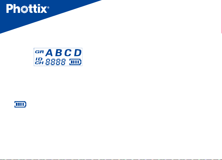
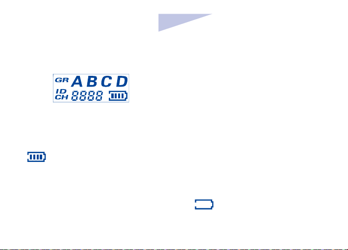
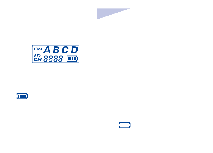
LCD display
1. GR: Group (A、B、C、D
2. ID :0000~9999 (Supported only when using
channels 5-16)
3. CH: Channels (1~16)
4.
Battery level display
:
)
Function and operation
Battery Installation
1. Press and hold the battery cover and push
in the direction indicated on the battery
cover to open. Remove the battery cover..
6
2. Install AA batteries.
3. Replace the battery cover and push back
into the locked position.
Caution: The Ares II circuitry is designed to
use with Alkaline, NI-CD or Ni-MH battery.
Do not use Lithium AA batteries
Powering Up/Down the Ares
II Transmitter and Receiver
1. Power Up:Press and hold the power
button for 2 seconds until the main interface
is displayed on the unit’s LCD.
2. Power Down: Press and hold the power
button for 2 second until the main interface
disappears from the unit’s LCD.
Page 7
En
INSTRUCTION MANUAL
3. When the battery power level icon “ ”
ashes, replace battery
Note:If the Ares II is powered on and
left idle for one hour, it will automatically
switched o.
.
Test button
1. Press the test button on the transmitter
any ash/ studio light connected to the Ares
II receivers set to the same channel, group
and Digital ID will trigger
2. Press the test button
to re the ash/studio light connected to the
receiver.
.
on the receiver
,
LED status light
1. When the transmitter and receiver are
powered up and idle,the LED status light
will ash green
2. When transmitter is sending commands or
the receiver is receiving commands, the LED
status light will light red.
,
。
Connecting the Ares II
Transmitter with camera hot
shoe
1. Switch o camera and transmitter
Connect the transmitter to camera hot shoe
2.
7
Page 8

3. Rotate the locking ring to tighten
4. Switch on camera and transmitter
discharge once after turning on the Ares II
Receiver
Connecting hot shoe ashes
to the Ares II Receiver
1. Turn o the ash and the Ares II Receiver.
2. Slide the ash into the receiver’s hot shoe
mount.
3. Lock the ash with the ash’s locking
mechanism.
4. Turn on the ash and the Ares II receiver.
5. Set the ash to Manual mode.
Note: It is not unusual for the ash to
8
Use sync cord to connect Ares
II receiver and hot shoe ash/
studio light
1. Switch o the hot shoe ash/ studio light
and the Ares II receiver
2. Connect one end of the 3.5mm sync cord
to the 3.5mm port of the Ares II receiver.
3. Connect the other end of the 3.5mm sync
cord to the hot shoe or studio light (use
the included 3.5mm to 6.3mm adapter if
required)
Page 9
En
INSTRUCTION MANUAL
4. Switch on the Ares II Receiver and hot shoe
ash/studio light
5. Set the hot shoe ash/studio light to
manual mode
Note: It is not unusual for the ash to
discharge once after turning on the Ares II
Receiver.
Transmission channels
,
Groups (GR) and Digital ID
The Ares II Flash Trigger System has
• Channels CH:1~16
• 4 ash group (GR):A、B、C、D
• Selectable Digital ID:0000~9999 (
Supported only when using channels 5-16).
:
The Ares II Transmitter
Setting the group, channels
and Digital ID on the
Transmitter
1. Press the Settings button to enter
channels and Digital ID settings interface.
2. Consecutively pressing the
cycle the display between channels or Digital
ID setting. The selected feature will ash to
indicate it is selected
3. Press the Selection Buttons Up or
Down
Digital ID value
to set Channels (CH) and
。
button to
9
Page 10

4. After setting options,press button to
conrm and exit the settings interface.
5. Each groups (GR) A,B,C,D have a
corresponding button on the transmitter.
Pressing the corresponding button will
activate or deactivate a group. Active Groups
will be displayed on the LCD, Inactive groups
will not be displayed on the LCD.
Note:
1. Digital ID is only available when using
Channels 5-16.
2. After making interface adjustments on
the transmitter, if
settings will be automatically conrmed 5
seconds.
10
button is not pressed,
The Ares II Receiver
Setting Groups (GR), channels (CH)
and Digital ID on Receiver
1. Press the Settings button to enter
channels and Digital ID settings interface.
2. Consecutively pressing the
cycle the display between channels, groups,or
Digital ID setting. The selected feature will
ash to indicate it is selected
3. Press the Selection Buttons Up or Down
to set Channels (CH), groups and
Digital ID value
4. After setting options,press
conrm and exit the settings interface.
button to
button to
Page 11
En
INSTRUCTION MANUAL
Note:
1.Digital ID is only available when using
Channels 5-16.
2. After making interface adjustments on
the receiver, if
settings will be automatically conrmed 5
seconds.
button is not pressed,
LCD Backlight Brightness
Setting
1. On the Ares II Transmitter or Receiver,
simultaneously press and hold the
button until the LCD displays“ ”.
the
2. Press
and to set the brightness of
and
the backlight value(1-8)
After setting the brightness level, press
to exit the adjustment screen.
Note: When transmitter or receiver is
left idle for more than 8 seconds, the
backlight will automatically turned
off.
11
Page 12
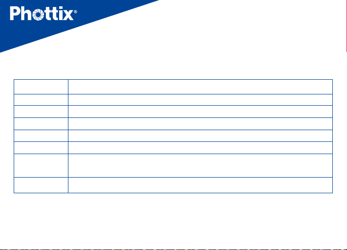
Technical specications
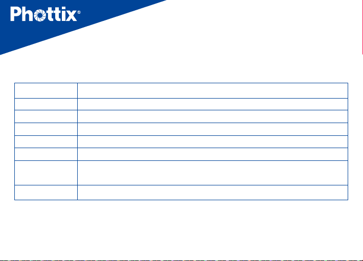
Frequency 2.4 GHz
Distance 150m+
Channels 16 channels
Groups (GR) 4 groups(A, B, C,D)
Digital ID 0000~9999 (5-16 channels)
Power source 2 AA batteries (Alkaline, Ni-CD, Ni-MH) for transmitter and receivers
Dimension (L92) x (W 46) x (H 41.5) mm(transmitter),
(L 92) x (W 46) x (H 44) mm (receiver)
Weight 65g(transmitter);70g(receiver)—(excluding batteries)
Note:Product design and specication is subject to change without notice
12
Page 13

En
INSTRUCTION MANUAL
Warning
• This product is a precise electronic
instrument. Do not expose to damp
environments or dust.
• Make sure all the devices’ power is switched
o before installing.
• Do not drop or crush.
• This product can not be used in a high
temperature, ammable and explosive
environment.
• If you do not plan to use your Odin TCU and
receiver for a long period of time, it is best
to remove the batteries to prevent possible
battery damage
Do not use harsh chemical(s) or solvents to
clean the body. Use a soft cloth or lens paper.
:
• Interference: The Phottix Ares II transmits
and receives radio signals at 2.4 GHz. Its
performance can be aected by electrical
current, magnetic elds, radio signals,
wireless routers, cellular phones, and other
electronic devices. Environmental objects,
such as large buildings or walls, trees, fences,
or cars can also aect performance. If your
Phottix Ares II receiver will not trigger move
its location slightly
13
Page 14

EC Declaration of Conformity
We Phottix (HK) Ltd.
Of Unit 1 & 13, 8/F., Block B, Hoi Luen Ind. Centre, 55 Hoi
Yuen Rd., Kwun Tong, Kln., Hong Kong
declare herewith that the product designated below:
Product name:
Phottix Ares II Flash Trigger Transmitter
complies with the relevant fundamental requirements as
per R&TTE Directive 1999/5/EC, insofar as the product is
used correctly, and the following standards or other nor
mative documents
ETSI EN 300 440-1 V1.6.1 (2010-08)
ETSI EN 300 440-2 V1.4.1 (2010-08)
ETSI EN301 489-1 V1.9.2/2011-09
ETSI EN301 489-17 V2.2.1/2012-09
-
Model No.: F0702
Product name: Phottix Ares II Flash Trigger Receiver
Model No.: F0701
14
EN 62479: 2010
Page 15
En
INSTRUCTION MANUAL
FCC Compliance Information
For Transmitter
Company: Phottix (HK) Ltd.
Phottix Ares II Flash Trigger Transmitter
Name:
Model Number:
FCC ID: P9M-ARES2TX
FCC Interference Statement:
This device complies with part 15 of the FCC Rules.
Operation is subject to the following two conditions:
(1) This device may not cause harmful interference, and
(2) this device must accept any interference received,
including interference that may cause undesired operation.
F0702
FCC Radiation Exposure Statement:
This equipment complies with FCC RF radiation exposure
limits set forth for an uncontrolled environment. This
device and its antenna must not be co-located or
operating in conjunction with any other antenna or
transmitter.
Class B Compliance Statement
NOTE: This equipment has been tested and found to
comply with the limits for a Class B digital device, pursuant
to Part 15 of the FCC Rules. These limits are designed to
provide reasonable protection against harmful interference
in a residential installation. This equipment generates, uses
and can radiate radio frequency energy and, if not installed
and used in accordance with the instructions, may cause
15
Page 16

harmful interference to radio communications. However,
there is no guarantee that interference will not occur in
a particular installation. If this equipment does cause
harmful interference to radio or television reception, which
can be determined by turning the equipment o and on,
the user is encouraged to try to correct the interference by
one or more of the following measures:
- Reorient or relocate the receiving antenna.
- Increase the separation between the equipment and
receiver.
- Connect the equipment into an outlet on a circuit
dierent from that to which the receiver is connected.
- Consult the dealer or an experienced radio/TV technician
for help.
16
Changes or modications not expressly approved by the
party responsible for compliance could void the user’s
authority to operate the equipment.
For Receiver
This device complies with Part 15 of the FCC Rules.
Operation is subject to the following two conditions: (1)
this device may not cause harmful interference, and (2) this
device must accept any interference received, including
interference that may cause undesired operation.
Changes or modications not expressly approved by the
party responsible for compliance could void the user’s
authority to operate the equipment.
Page 17

感谢您购买 Phottix 产品
在使用 Ares II 无线电触发器前请务必
注意:
通读本使用说明书 , 相机和闪光灯的使用方
法,以保证您熟悉操作,正确使用。
Ares II 无线触发器是为手动曝光模式设计的
无线闪光灯引闪系统,由发射器和接收器组
成。本产品采用 2.4GHz 频率,并设有 16 个
无 线 电 频道 CH,ID(0000 ~ 9999) 和 4
个闪光组 GR,性能稳定,操作简便,适合各
种场合布光使用。
17
兼容性
1.Ares II 在 1 ~ 4 频道时兼容 Strato II 系统,
只需发射端和接收器设置为同一频道,对应
组别:
• 发射器可以触发 Strato II 接收器,以及设
为 Strato II RX 模式下的 Indra 系列影楼灯
和 Mitros+ 系列闪光灯;
• 接收器可以被 Strato II 发射器触发,也可
以被 Odin,Odin II 发射 器或 Odin TX 模
式下的 Mitros+ (佳能或索尼版)触发。
2.Ares II 在 5~ 16 频道,与其他产品不兼容,
发射器和接收器必须配套使用。
Page 18

Cn
Simp
说明书
包装配件
发射接收套装
1. 发射器 -1pc
2. 接收器 -1pc
3. 挂包 -1pc
4. Phottix 带插头软线
3.5+3.5/40cm-1pc
5. 6.3 转接头 -1pc
6. 挂绳 -2pcs
7. 说明书 -1pc
8. 保修卡 -1pc
单发射
1. 发射器 -1pc
2. 说明书 -1pc
3. 挂绳 -1pc
4. 保修卡 -1pc
单接收
1. 接收器 -1pc
2. 说明书 -1pc
3. Phottix 带插头软线
3.5+3.5/40cm-1pc
4. 6.3 转接头 -1pc
5. 挂绳 -1pc
6. 保修卡 -1pc
18
Page 19
一 . 部件名称
发射器
1. 电源开关
2. LCD 显示屏
3. 设置按钮
4. 组别按钮 GR( 从左到右依次为 A,B,C,D)
5. 测试按钮
6. 选择按钮(上键)
7. 确认按钮
8. 选择按钮(下键)
9. LED 指示灯
10. 吊环口
11. 电池仓盖
12. 锁环
13. 电子触点
14. 热靴固定座
15. 固定销
Simp
Cn
10
1 5
2
3
4
说明书
9
6
7
8
11
15
12
13
14
19
Page 20
接收器
1. 电源开关
2. LCD 显示屏
3. 热靴座
4. 设置按钮
5. 测试按钮
6. 选择按钮(上键)
7. 确认按钮
8. 选择按钮 (下键)
9. LED 指示灯
10. 吊环口
11. 锁环
12. 三脚架螺口 / 冷靴插座
13. 电池仓盖
14. 3.5mm 同步端口
20
10
14
1
2
3
4 12
5
6
7
8
9
11
13
Page 21
Cn
Simp
说明书
LCD 显示
1. GR: 组别(A、B、C、D)
2. ID :0000 ~ 9999 (仅 5 ~ 16 频道时)
3. CH: 频道 (1 ~ 16)
4.
: 电量显示
功能和操作
安装电池
1. 按电池盖,并按箭头所示方向推开电池盖,
从机身拆下电池盖;
2. 装入 AA电池,注意确保电池的 +/- 极性;
3. 放回电池盖,将其推至锁紧位置。
注意:安装电池时,请使用两节 AA 型碱
性电池 , NI-CD 或 Ni-MH 电池。请勿使
用 AA 锂电池。
开启 / 关闭发射器和接收器
1. 开启:按住电源按钮直至主界面出现在
液晶屏上 ( 约 2s)。
2. 关闭:按住电源按钮直至液晶屏上无显
示 ( 约 2s)。
3. 当发射器和接收器上的电量图标闪烁
“ ”,请更换电池。
注:开机后如闲置无操作,发射器和接
收器 1 小时后会自动关机。
21
Page 22
测试按钮
1. 按下发射器的测试按钮 ,与之相同频
道 CH,组别 GR,ID 设定下的所有接收器
所连接的闪光灯 / 影楼灯都将会被触发。
2. 按下接收器的测试按钮
接在此接收器上面的闪光灯 / 影楼灯。
将会触发连
将发射器连接于相机热靴插座
1. 关闭相机和发射器;
2. 将发射器插入相机的热靴插座;
3. 旋转发射器锁环至锁紧;
4. 开启相机和发射器。
LED 指示灯
1. 当电源开着且闲置时,发射器和接收器
的 LED 指示灯闪绿灯。
2. 发射器发送指令,接收器接收指令时,
LED 指示灯亮起红灯。
22
将闪光灯连接到接收器的热靴上
1. 关闭闪光灯和接收器;
2. 将闪光灯插入接收器的热靴插座;
3. 用闪光灯的锁紧机构锁紧闪光灯;
4. 开启闪光灯和接收器;
5. 将闪光燈设置为手动模式。
Page 23
Cn
Simp
说明书
通过连接线连接 Ares II 接收器和闪
光灯 / 影楼灯
1. 关闭闪光灯 / 影楼灯和 Ares II 接收器。
2. 将 3.5mm 连接线的一端插入接收器上的
3.5 mm 端口。
3. 将3.5mm 连接线的另一端连接到闪光
灯 / 影楼灯(附送用于影楼灯的大端口的
6.3mm 适配器)。
4. 开启闪光灯 / 影楼灯和 Ares II 接收器。
5. 将闪光灯设置为手动模式(M)
* 当开启 Ares II 时,闪光灯闪光一次是
属于正常现象。
传输频道,闪光组 GR 和 ID
1.Ares II 无线系统有:
•
频道 CH:1 ~ 16
•
4 个闪光组 GR:A、B、C、D
•
可设置无线电 ID:0000 ~ 9999 (仅
5 ~ 16 频道时)。
设置发射器的频道,组和 ID
1. 按 键进入频道 CH 和 ID 设置状态。
注:如果当前在 5 ~16 频道,可以按
或 选择设置频道 CH 或 ID,再
按
进入设置状态;
23
Page 24
2. 连续按 在频道 CH 或四位 ID 数之间
循环,设置状态下,所选项会闪烁显示。
3.按 或 设定频道 CH 以及 ID 数值;
4. 设置完成后,按
5. 发射器的 A,B,C 和 D 组 GR 分别有对应
的组别按钮,按对应的组别按钮,即可打开
或关闭组別。LCD 屏上的组别 GR 显示,表
示该组为打开状态;无显示则表示该组关闭。
退出设定状态。
设置接收器的频道,组和 ID
1. 按 键进入频道、ID 和组的设置状态。
注:如果当前在 5 ~ 16 频道,可以按
24
或
选择设置频道或 ID,再按 进入
设置状态;
2. 连续按
间循环设置状态下,所选项会闪烁显示。
3. 按
值和组别。
4. 设置完成后,按
注意:完成设置后,如不按
5s 后发射器和接收器会自动确认设定。
在频道,组以及四位 ID 数之
或 设定接收器频道、ID 数
退出设定状态。
退出,
Page 25
背光灯亮度调节
发射器和接收器的背光灯亮度可以进行调
节:
Cn
Simp
说明书
1. 在关机状态,同时按住
显示屏显示“
2. 按
”字样。
或 设定背光灯的亮度值
和 直到
(1 ~ 8)。
3. 设置完成后,按
退出设定状态。
注:发射器和接收器闲置状态下,8s后
背光灯会自动熄灭。
25
Page 26
技术参数
频率 2.4 GHz
距离 150m+
频道 16个频道
组 4个组( A, B, C,D)
无线电ID 0000~9999(5~16频道)
供电方式 2节AA型碱性, Ni-CD或Ni-MH电池
主体尺寸 (L92) x (W 46) x (H 41.5) mm(发射器),
(L 92) x (W 46) x (H 44) mm (接收器)
重量 65g(发射器);70g(接收器)—(不含电池)
注:当产品的设计和规格有变化时,恕不另行通知。
26
Page 27

Cn
Simp
说明书
警告:
• 本产品属精密电子仪器,请注意防潮防尘。
• 安装本产品时请务必关闭所有装置电源。
• 请勿摔落或敲击本产品。
• 请勿在易爆易燃或高温环境中使用本产
品。
• 长时间不使用时,请将电源关闭并将电池
取出。
• 请勿用化学或有机溶剂清洁机身 , 请用柔
软干净的布或镜头纸对其外表面进行擦拭。
• 干扰:Phottix Ares II 以 2.4GHz 传送和
接收无线电信号。它在使用时可能受到电
流,磁场和无线电信号、无线路由器、移动
电话以及其他电子设备的影响,还诸如大
型建筑或墙壁,大树,栅栏或汽车等周边
事物的影响。如果您的接收器不能被触发,
请稍微移动它的位置。
27
Page 28

Cn
Trad
說明書
感謝您購買 Phottix 產品
在使用 Ares II 無線電觸發器前請務必
注意:
通讀本使用說明書 , 相機和閃光燈的使用方
法,以保證您熟悉操作,正確使用。
Ares II 無線觸發器是為手動曝光模式設計的
無線閃光燈引閃系統,由發射器和接收器組
成。本產品採用 2.4GHz 頻率,並設有 16 個
無線電頻道,ID(0000 ~ 9999)和 4 個閃
光組,性能穩定,操作簡便,適合各種場合
布光使用。
相容性
1.Ares II 在 1 ~ 4 頻道時相容 Strato II 系統,
只需發射端和接收器設置為同一頻道,對應
組別:
• 發射器可以觸發 Strato II 接收器,以及設
為 Strato II RX 模式下的 Indra 系列影樓燈
和 Mitros+ 系列閃光燈;
• 接收器可以被 Strato II 發射器觸發,也可
以被 Odin,Odin II 發射 器或 Odin TX 模
式下的 Mitros+ (佳能或索尼版)觸發。
2.Ares II 在 5~ 16 頻道,與其他產品不相容,
發射器和接收器必須配套使用。
28
Page 29

包裝配件
發射接收套裝
1. 發射器 -1pc
2. 接收器 -1pc
3. 掛包 -1pc
4. Phottix 帶插頭軟線
3.5+3.5/40cm-1pc
5. 6.3 轉接頭 -1pc
6. 掛繩 -2pcs
7. 說明書 -1pc
8. 保修卡 -1pc
29
單發射
1. 發射器 -1pc
2. 說明書 -1pc
3. 掛繩 -1pc
4. 保修卡 -1pc
單接收
1. 接收器 -1pc
2. 說明書 -1pc
3. Phottix 帶插頭軟線
3.5+3.5/40cm-1pc
4. 6.3 轉接頭 -1pc
5. 掛繩 -1pc
6. 保修卡 -1pc
Page 30
部件名稱
發射器
1. 電源開關
2. LCD 顯示幕
3. 設置按鈕
4. 組別按鈕(從左到右依次為 A,B,C,D)
5. 測試按鈕
6. 選擇按鈕(上鍵)
7. 確認按鈕
8. 選擇按鈕(下鍵)
9. LED 指示燈
10. 吊環口
11. 電池倉蓋
12. 鎖環
13. 電子觸點
14. 熱靴固定座
15. 固定銷
Trad
Cn
10
1 5
2
3
4
說明書
9
6
7
8
11
15
12
13
14
30
Page 31
接收器
1. 電源開關
2.LCD 顯示幕
3. 設置按鈕
4. 熱靴座
5. 測試按鈕
6. 選擇按鈕(上鍵)
7. 確認按鈕
8. 選擇按鈕 (下鍵)
9. LED 指示燈
10. 吊環口
11. 鎖環
12. 三腳架螺口 / 冷靴插座
13. 電池倉蓋
14. 3.5mm 同步端口
31
10
14
1
2
3
4 12
5
6
7
8
9
11
13
Page 32
Cn
Trad
說明書
LCD 顯示
1.GR: 組別(A、B、C、D)
2.ID :0000 ~ 9999 (仅 5 ~ 16 频道时)
3.CH: 頻道 (1 ~ 16)
4.
: 電量顯示
功能和操作
安裝電池
1. 按電池蓋,並按箭頭所示方向推開電池蓋,
從機身拆下電池蓋;
2. 裝入 AA電池,注意確保電池的 +/- 極性;
3. 放回電池蓋,將其推至鎖緊位置。
注意:安裝電池時,請使用兩節 AA 型鹼
性電池 , NI-CD 或 Ni-MH 電池。請勿使
用 AA 鋰電池。
開啟 / 關閉發射器和接收器
1. 開啟:按住電源按鈕直至主介面出現在
液晶屏上 ( 約 2s)。
2. 關閉:按住電源按鈕直至液晶屏上無顯
示 ( 約 2s)。
3. 當發射器和接收器上的電量圖示閃爍
“ ”,請更換電池。
注:開機後如閒置無操作,發射器和接
收器 1 小時後會自動關機。
32
Page 33
測試按鈕
1. 按下發射器的測試按鈕 ,與之相同頻
道,組別,ID設定下的所有接收器所連接
的閃光燈 / 影樓燈都將會被觸發。
2. 按下接收器的測試按鈕
接在此接收器上面的閃光燈 / 影樓燈。
將會觸發連
將發射器連接於相機熱靴插座
1. 關閉相機和發射器;
2. 將發射器插入相機的熱靴插座;
3. 旋轉發射器鎖環至鎖緊;
4. 開啟相機和發射器。
LED 指示燈
1. 當電源開著且閒置時,發射器和接收器
的 LED 指示燈閃綠燈。
2. 發射器發送指令,接收器接收指令時,
LED 指示燈亮起紅燈。。
33
將閃光燈連接到接收器的熱靴上
1. 關閉閃光燈和接收器;
2. 將閃光燈插入接收器的熱靴插座;
3. 用閃光燈的鎖緊機構鎖緊閃光燈;
4. 開啟閃光燈和接收器;
5. 將閃光設置為手動模式。
Page 34
Cn
Trad
說明書
通過連接線連接 Ares II 接收器和閃
光燈 / 影樓燈
1. 關閉閃光燈 / 影樓燈和 Ares II 接收器。
2. 將 3.5mm 連接線的一端插入接收器上的
3.5 mm 端口。
3. 將3.5mm 連接線的另一端連接到閃光
燈 / 影樓燈(附送用於影樓燈的大端口的
6.3mm 適配器)。
4. 開啟閃光燈 / 影樓燈和 Ares II 接收器。
5.將閃光燈設置為手動模式(M)(如果
相容的閃光燈是通過連接線觸發,就不能採
用 TTL 功能。)
* 當開啟 Ares II 時,閃光燈閃光一次是
屬於正常現象。
傳輸頻道,閃光組和 ID
1. Ares II 無線系統有:
•
频道 CH:1 ~ 16
•
4 個閃光組 GR:A、B、C、D
•
可設置無線電 ID:0000 ~ 9999 (僅
5 ~ 16 頻道時)。
設置發射器的頻道,組和 ID
1. 按 鍵進入頻道 CH 和 ID 設置狀態。
注:如果當前在 5 ~16 頻道,可以按
或 選擇設置頻道 CH 或 ID,再
按
進入設置狀態;
34
Page 35
2. 連續按 在頻道 CH 或四位 ID 數之間
迴圈,設置狀態下,所選項會閃爍顯示。
3.按 或 設定頻道 CH 以及 ID 數值;
4. 設置完成後,按
5. 發射器的 A,B,C 和 D 組 GR 分別有對應
的組別按鈕,按對應的組別按鈕,即可打
開或關閉組別。LCD 屏上的組別 GR 顯示,
表示該組為打開狀態;無顯示則表示該組關
閉。
退出設定狀態。
設置接收器的頻道,組和 ID
1. 按 鍵進入頻道、ID 和組的設置狀態。
注:如果當前在 5 ~ 16 頻道,可以按
35
選擇設置頻道 CH 或 ID,再按
或
進入設置狀態;
2. 連續按
ID 數之間迴圈設置狀態下,所選項會閃爍
顯示。
3. 按
道 CH 和 ID 數值。
4. 設置完成後,按
注意:完成設置後,如不按
5s 後發射器和接收器會自動確認設定。
在頻道 CH,組 GR 以及四位
或 設定接收器組別 GR、頻
退出設定狀態。
退出,
Page 36
背光燈亮度調節
發射器和接收器的背光燈亮度可以進行調
節:
Cn
Trad
說明書
1. 在關機狀態,同時按住
顯示幕顯示“
2. 按
”字樣。
或 設定背光燈的亮度值
和 直到
(1 ~ 8)。
3. 設置完成後,按
退出設定狀態。
注:發射器和接收器閒置狀態下,8s後
背光燈會自動熄滅。
36
Page 37
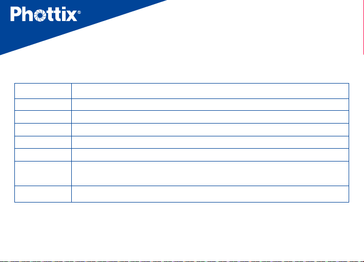
技術參數
頻率 2.4 GHz
距離 150m+
頻道CH 16個頻道
組GR 4個組( A, B, C,D)
無線電ID 0000~9999(5~16頻道)
供電方式 2節AA型鹼性, Ni-CD或Ni-MH電池
主體尺寸 (L92) x (W 46) x (H 41.5) mm(發射器),
(L 92) x (W 46) x (H 44) mm (接收器)
重量 65g(發射器);70g(接收器)—(不含電池)
注:當產品的設計和規格有變化時,恕不另行通知。
37
Page 38

Cn
Trad
說明書
警告:
• 本產品屬精密電子儀器,請注意防潮防塵。
• 安裝本產品時請務必關閉所有裝置電源。
• 請勿摔落或敲擊本產品。
• 請勿在易爆易燃或高溫環境中使用本產
品。
• 長時間不使用時,請將電源關閉並將電池
取出。
• 請勿用化學或有機溶劑清潔機身 , 請用柔
軟乾淨的布或鏡頭紙對其外表面進行擦拭。
• 干擾:Phottix Ares II 以 2.4GHz 傳送和
接收無線電信號。它在使用時可能受到電
流,磁場和無線電信號、無線路由器、移動
電話以及其他電子設備的影響,還諸如大
型建築或牆壁,大樹,柵欄或汽車等周邊
事物的影響。如果您的接收器不能被觸發,
請稍微移動它的位置。
38
Page 39
39
 Loading...