

Page 1

Odin II TTL Flash Trigger for Canon
Thank you for purchasing a Phottix product
Note: Before using the Odin II TTL Flash Trigger for Canon, please read this
instruction manual carefully.
Odin II TTL Flash Trigger is a new generation of TTL triggering system based on the
previous Odin TTL Flash Trigger. While keeping the Odin system’s core functions
such as of wireless power level adjustment, zoom adjustment and etc, the new system
has been added with a series of innovative functions to extend its utility and stability,
including group/channel/ID settings, AF assist light, wireless modeling light
brightness control. A whole new structural design allows for easier and faster to
operation.
Many TTL flashes have been tested but the manufacturer cannot guarantee that all
third party TTL flashes will function properly with the Phottix Odin II. It is designed
and optimized for Canon Flashes using the ETTL II/ETTL system.
Please Note:
1. After turning on the Phottix Odin II transmitter and receivers, slave mode does
not need to be set on flashes on Photix Odin II receivers, but flashes need to be set
in ETTL mode.
2. Ensure there is a good hot shoe connection between the transmitter and camera,
flashes and receivers for best performance.
3. Many TTL flashes have been tested but the manufacture cannot guarantee that all
third party TTL flashes will function properly with the Phottix Odin II. It has been
designed and optimized for original canon flashes using the ETTL II/ETTL system.
4. Turn of all devices-flashes/strobes, camera, and the Phottix Odin II transmitter
and receivers when connecting and disconnecting the devices.
FCC Interference Statement:
This device complies with part 15 of the FCC Rules. Operation is subject to the
following two conditions: (1) This device may not cause harmful interference, and (2)
this device must accept any interference received, including interference that may
cause undesired operation.
FCC Radiation Exposure Statement:
This equipment complies with FCC RF radiation exposure limits set forth for an
uncontrolled environment. This device and its antenna must not be co-located or
Page 2

operating in conjunction with any other antenna or transmitter.
NOTE: This equipment has been tested and found to comply with the limits for a
Class B digital device, pursuant to Part 15 of the FCC Rules. These limits are
designed to provide reasonable protection against harmful interference in a
residential installation. This equipment generates, uses and can radiate radio
frequency energy and, if not installed and used in accordance with the instructions,
may cause harmful interference to radio communications. However, there is no
guarantee that interference will not occur in a particular installation. If this
equipment does cause harmful interference to radio or television reception, which can
be determined by turning the equipment off and on, the user is encouraged to try to
correct the interference by one or more of the following measures:
-- Reorient or relocate the receiving antenna.
-- Increase the separation between the equipment and receiver.
-- Connect the equipment into an outlet on a circuit different from that to which the
receiver is connected.
-- Consult the dealer or an experienced radio/TV technician for help.
The product is classified as Class 3R laser product,
according to the following standards IEC/EN
60825-1 "Radiation Safety of Laser Products."
Class 3R: A Class 3R laser is considered safe if
handled carefully, with restricted beam viewing.
With a class 3R laser, the MPE can be exceeded, but
with a low risk of injury. Visible continuous lasers in
Class 3R are limited to 5mW. For other wavelengths
and for pulsed lasers, other limits apply.
Table of Content
I. Parts
II. Preparation Before Use
III. LCD Display
IV. Functions and Operations
V. Custom Function Settings
Page 3
VI. Technical Specifications
VII. Warnings
I. Parts
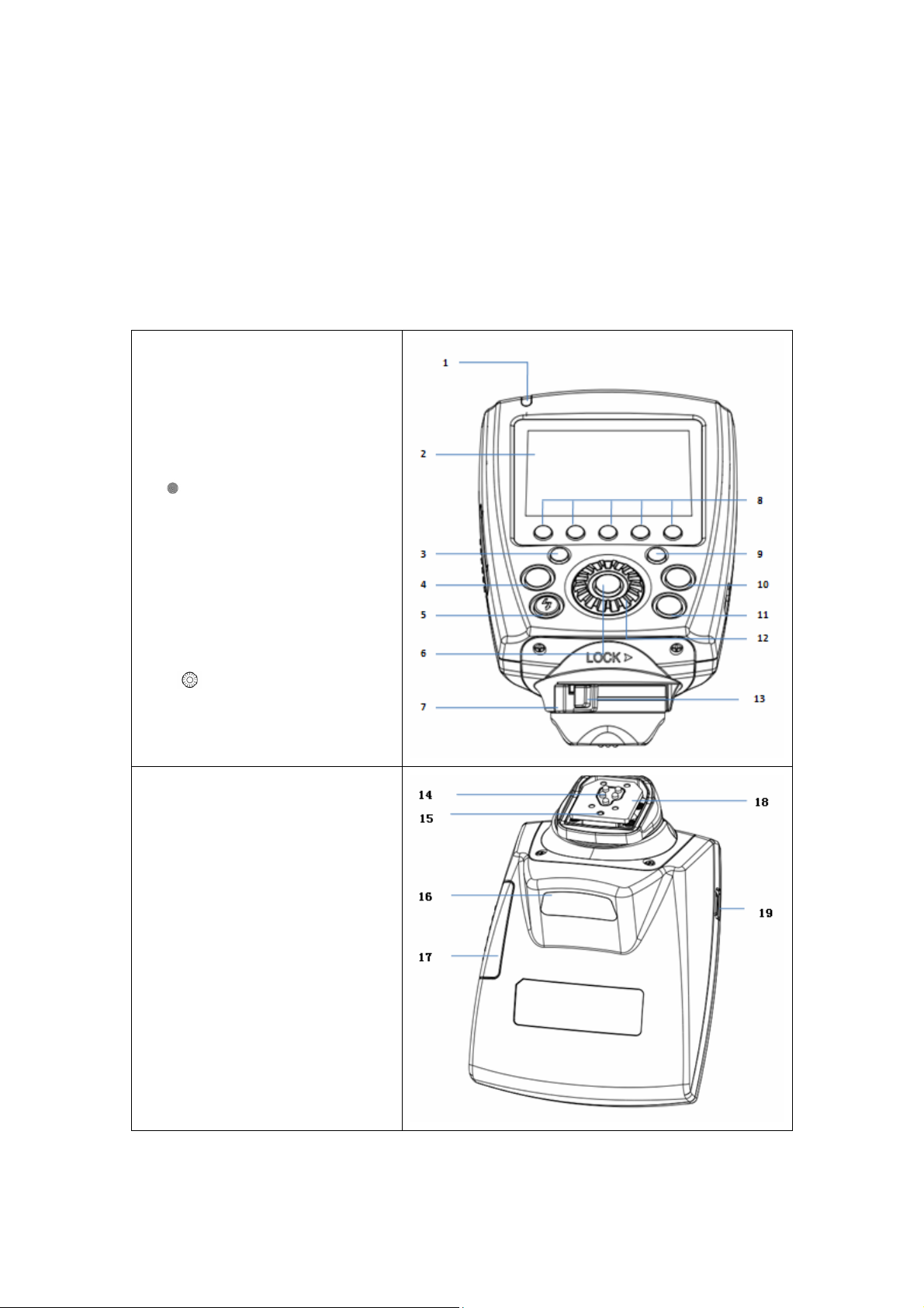
Transmitter
1. LED Indicator
2. LCD Screen
3. Zoom Button
4. Mode Button
5.Test Button/Flash Exposure
Confirmation Lamp
6.< >:Select/Set Button
7.Locking Ring
8.Group Button(From right to left
are A, B, C, D, E consecutively)
9.Power Button/Menu Button
10. High Speed Sync Button
(HSS)
11. Modeling Light Button
12. < >: Select Dial
13. Lock-release Button
14.Contacts
15.Locking Pin
16.AF Assist Light
17. Battery Compartment
18. Mounting Foot
19..USB Port
Page 4
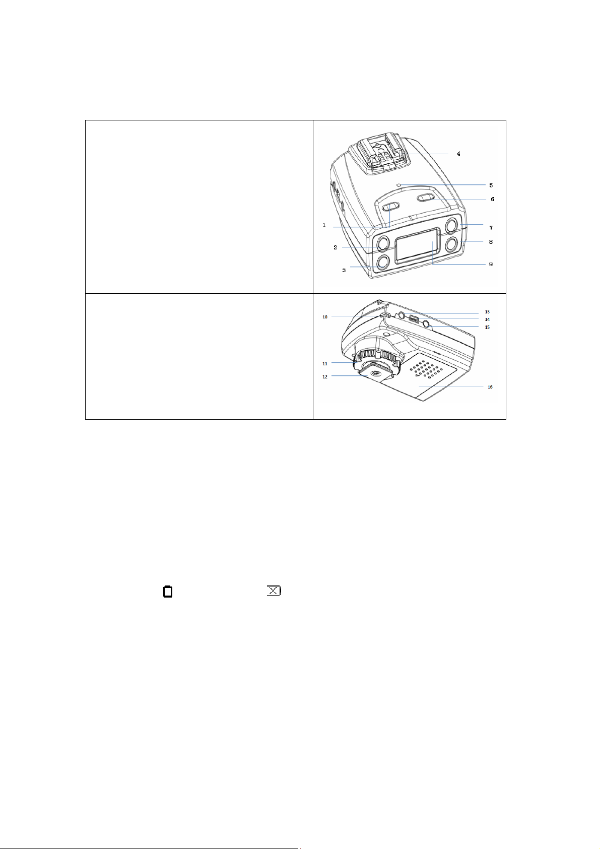
Receiver
1. Power Button
2. Channel Button/Select Button+
3. Group Button/Select Button-
4. Hot Shoe
5. LED Indicator
6. Test Button
7. ID Button/Digit select Button
8. Exit Button
9. LCD Display
10. Carrying Strap Slog
11. Locking Ring
12. Cold Shoe/ ¼” Tripod Lug
13. 3.5mm Output Port
14. USB Port
15. 5V DC Power Port
16. Battery Compartment
II. Preparation Before Use
Installing the Batteries
1. Press the battery compartment cover on Phottix Odin II transmitter and
receiver, slide it down as directed to open the battery cover.
2. Insert the batteries. Make sure the “+” and“-”battery contacts are correctly
oriented as shown. (Note: Please use 2 pieces of AA alkaline batteries or AA
type NI-MH batteries.
3. Replace the battery cover and push back into the locked position.
4. When (transmitter) and (receiver) are displayed, please replace the
batteries with new ones.
Attaching and Detaching the Odin II
Attaching the Odin II transmitter to the camera hot shoe:
1. Turn off the camera and transmitter
2. Align the transmitter hot shoe with camera’s hot shoe mount.
3. Slide the transmitter all the way into the camera’s hot shoe mount.
4. Lock release: press the lock-release button while slide the lock lever all the
way back to the left.
Page 5

Attaching the flash to the Odin II receiver
1. Insert the flash hot shoe all the way into the receiver’s hot shoe mount
2. Lock the flash with the flash’s locking mechanism.
3. Detaching: Release the lock of flash according to its locking mechanism, and
then slide the flash out of the receiver’s hot shoe mount.
Attaching the Odin II Receiver to Studio Lights or Flashes by Cable
1. Turn off the flash/strobe and the Odin II receiver.
2. Connect a cable to the receiver’s 3.5 mm output port.
3. Connect the opposite end of the cable to a flash or studio strobe
4. Turn on the flash/strobe and Odin II receiver
5. Set the flash to Manual mode – no ETTL functions can be used when a
compatible flash is triggered by cable.
Turn on/off the Transmitter and Receiver
1. Turn On: Press and hold the power button until MENU interface is displayed on
screen.
2. Turn off: Press and hold the power button until the LCD screen goes blank.
Firing Group, Channel and ID Setting
1. The Phottix Odin II system has up to 5 groups: A, B, C, D, E, 32 channels and
settable IDs from 0000 to 9999.
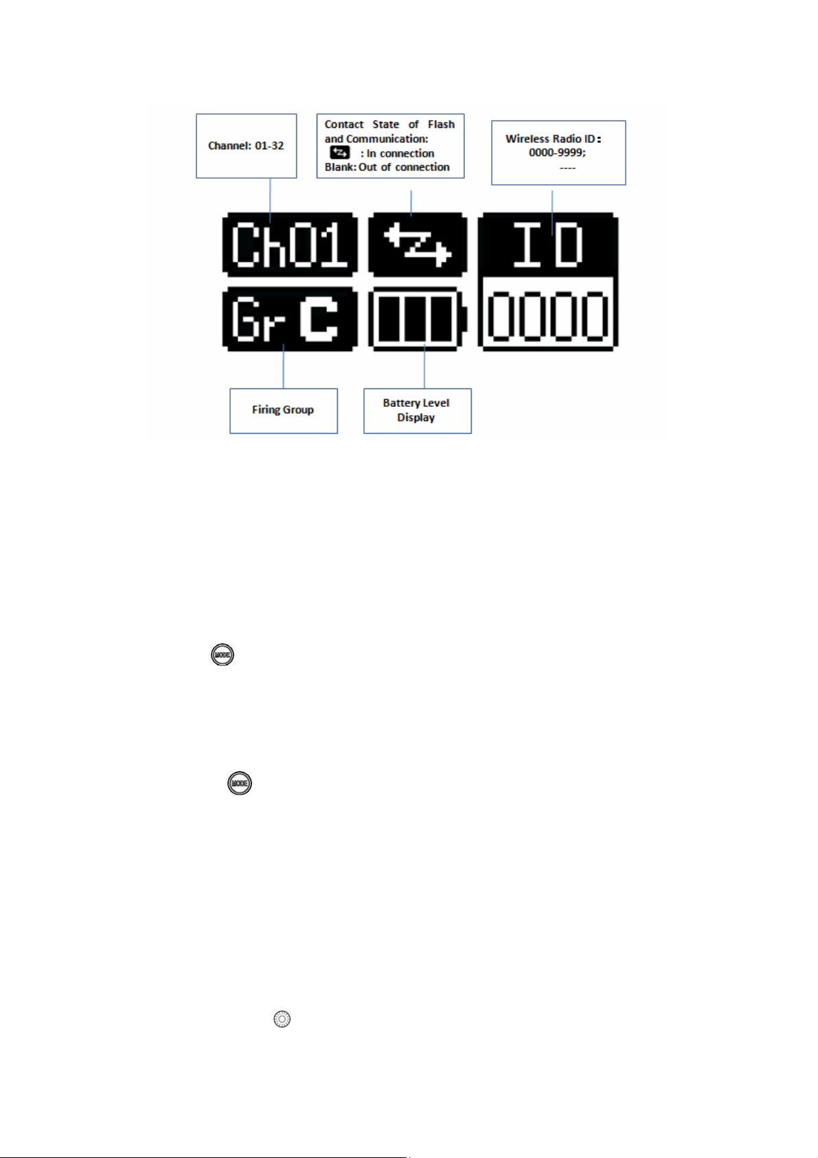
2. Receivers can be assigned group, channels and ID designation.
3. The transmitter will allow EV, Power level and Zoom setting adjustments to be set
for each group of receivers set the same channel and ID (unless the group is set to
OFF on the transmitter.
4. Set the channel, group and ID as following
1)The channel, group and ID of transmitter can be set in the custom function. For
operations, please refer to Custom Function setting.
2)Set the channel for receiver: press button; the channel parameter will flash
on the LCD screen; Press or button to set the channel; press button to
exit the setting mode.
3)Set the group for receiver: Press
the screen; press
or to set the group; press button to exit the setting
button; the group parameter will flash on
mode.
4) Set the ID for receiver: Press to choose the ID digit to be set; press
Page 6
or to set the ID value for the chosen digit; Press to exit the setting
mode. Repeat the operation to set value for the 4 ID digits one by one.
Note: The Odin II is at its compatibility mode with Odin I when set to 1-4 channels.
Under the mode, the transmitter can only control 3 groups (A, B, C), the group D and
E will not be displayed on the screen, nor can the IDs be settable.
Upgrading firmware by USB
The firmware of the transmitter and receivers can be upgraded using the included
USB cable. Any upgrades and full instructions will be announced on the Phottix blog
(journal.phottix.com).
III. LCD Display
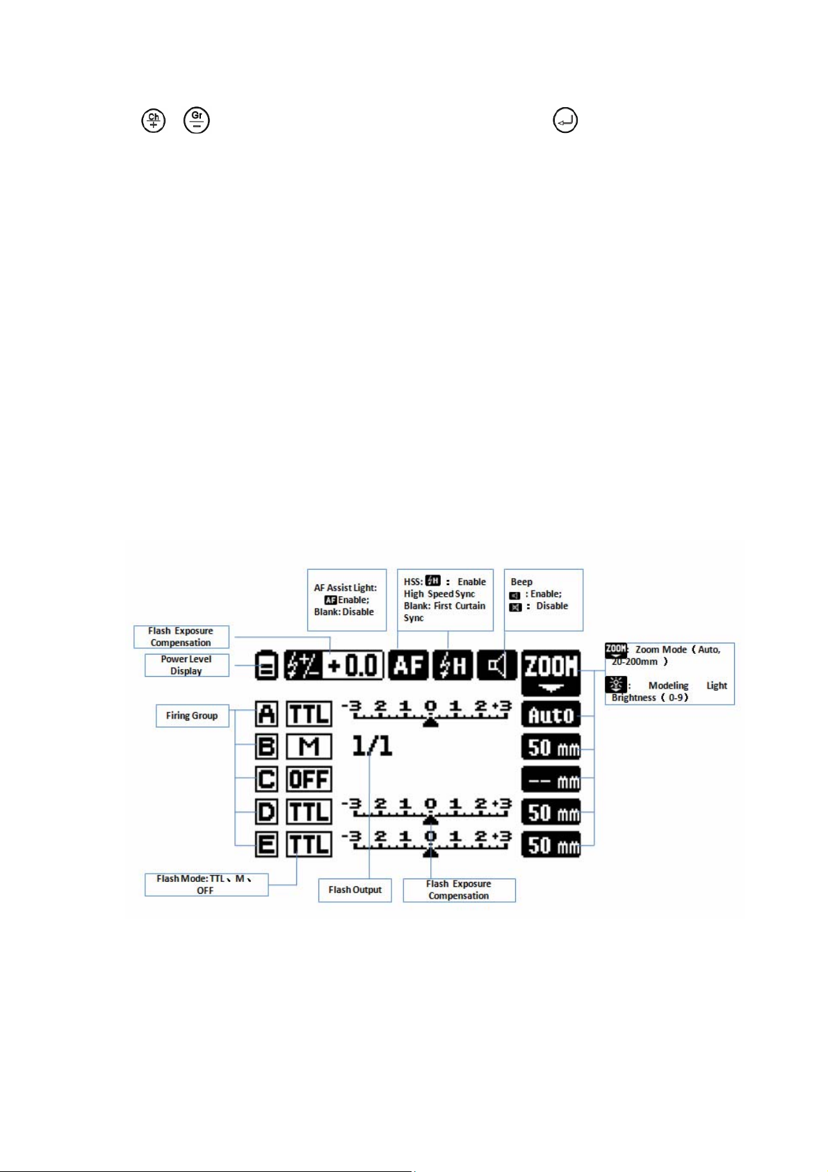
Transmitter
The transmitter has two working modes: TTL/M Mixed Functions and Ratio
Functions. The two different working modes are displayed as following:
TTL/M Mixed Functions Screen(channel 5-32):
TTL/M Mixed Functions Screen(channel 1-4):
Page 7
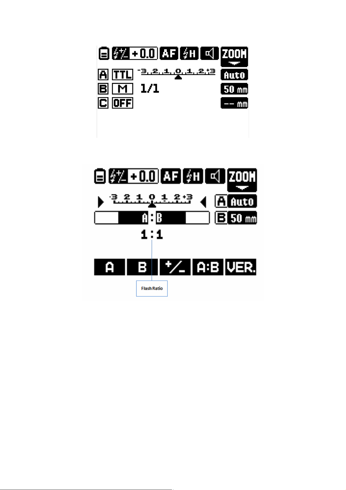
Ratio Functions Screen
Receiver
Page 8
IV. Functions and Operations
To Set the Working Mode
TTL/M Mixed Functions Screen allows you to set to TTL, Manual and OFF for
A/B/C/D/E independently, along with the EV and Power Level for each group.
The Ratio Functions Screen is similar to a original Canon TTL system. You can set
the flash ratio for group A and B from 8:1 to 1:8, and the EV as well.
Pressing the button on transmitter will cycle through TTL/M TTL/M Mixed
Functions and Ratio Functions.
TTL/M Mixed Functions
To set flash mode for each group: Press the group button to choose the group to set,
and then press
TTL: Will fire flashes using TTL metering. The EV level of each group can be
adjusted within ±3 stop in 1/3-stop increment.
Manual: Flashes are set in Manual mode and power levels adjusted within
1/1-1/128 in 1/3-stop increment.
OFF: Selecting OFF will turn off the selected group and not fire any remote flashes
in the group.
To adjust the EV Level or Power Level for each group: Press group button to choose
the group to set, turn to set the EV or Power Level for the selected group.
button to choose the flash mode from TTL, Manual and OFF.
Page 9
Upon adjustment, press button on transmitter to exit the setting mode.
Ratio Functions
1. To set the Flash Ratio
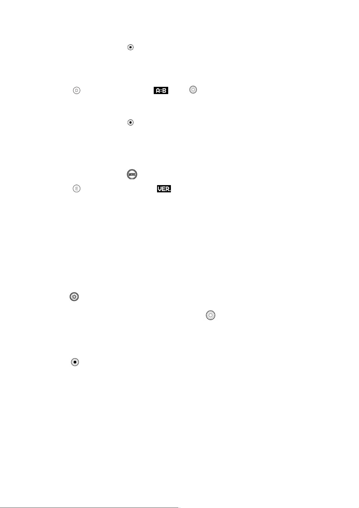
Press button corresponding to , turn to set the flash ratio from 8:1 to 1:8
in 1/2stop increment.
Upon adjustment, press button to exit the setting mode.
2. Check the Version Info
The Odin II transmitter allows for check the version information at the Ratio
Functions Screen. Press button to display the Ratio Function Screen, and then
press button corresponding to to display the current version information of
the transmitter.
LED Indicator
When left idle, the LED indicators on transmitter and receiver will flash green at
certain frequency. When the camera is in action of focusing, the indicators will light
green; while in action of shooting, the indicators will light red.
Modeling Light Button
Pressing the modeling light button on the transmitter will allow you to adjust the
modeling light brightness (0-9 grades) of Phottix Indra studio light series:
Press button to display the screen for modeling light brightness adjustment; press
the group button to choose the group to set; turn to set the brightness level of
modeling light. Repeat the above operation to set the brightness level of modeling
light for each group.
Press button to exit the setting mode.
Note: The function is not available for hot shoe flashes.
LCD Backlight
The backlight will light up for 8 seconds when pressing any button on the transmitter
and then go off if no buttons are pressed. You can enable or disable the LCD backlight
by setting custom function.
Page 10
Test Button/Flash Exposure Confirmation Lamp( )
1. Pressing the test button will cause to A/B/C/D/E group to fire simultaneously,
conditioned that the flash attached to receivers are set to the corresponding
channel and group and ID.
2. The flash exposure confirmation lamp will light red when the transmitter is left
un-operated. While the camera is focusing, the lamp will turn out and after
pressing the shutter, the lamp will light green.
To Adjust the Flash Zoom
Phottix Odin II allows the zoom level of flashes to be set wirelessly as Auto or
Manual:
Auto Zoom: Flash zoom setting will change dynamically as a camera zoom ring is
adjusted.
Manual Zoom: Flash zoom can be set to a fixed value on the transmitter. Any
changes made to camera zoom will not affect this setting.
1. When adjusting the flash zoom wirelessly, set the flash on receiver to Azoom.
2. Set the Odin II transmitter as following:
1) Press the zoom button to display zoom setting screen.
2) Press group button to select to group to set, turn to set the zoom mode to
Auto or simply adjust the zoom manually from(20-200mm). Repeat the
operation to set zoom value for each group one by one.
3) Press button to exit the zoom setting screen.
Flash Exposure Compensation(EV)
You can adjust the EV for all the groups altogether within ±3 in 1/3-stop increments
on Odin II transmitter. See below:
1. TTL/M Mixed Functions Screen:
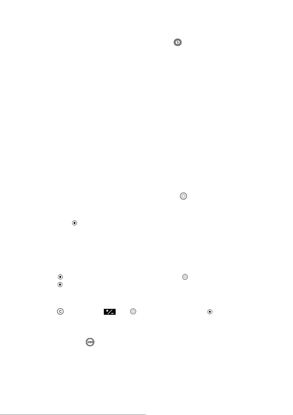
Press button to display the EV setting screen, turn to set the EV and then
press
to exit the screen.
2. Ration Function Screen
Press corresponding to , turn to set the EV and then press button to exit
the setting mode.
HSS Function( )
HSS will allow shutter speeds longer than a compatible camera specified shutter
speed to be used. Shutter speed up to 1/8000 sec. can be achieved with compatible
cameras and flashes.
Page 11

1. Press button to enable HSS. Icon will be displayed on the LCD screen.
2. Press button again to disable the HSS function and switch to first curtain
sync.
High Speed Continuous Shooting
Using the Phottix Odin II will result in slower continuous high speed shooting than
can be achieved when using a flash directly on the camera. There are differences in
metering between the Phottix Odin system related to groups and the pre-flashes than
Canon’s native system.
Note:
1. High speed continuous shooting function cannot be set on the Odin II transmitter.
2. High speed continuous shooting function needs to e set on camera. Refer to your
camera manual for specific menu settings.
AF Assist Light
In low light/contrast situation, you can enable the AF assist light on transmitter by
setting custom function. The transmitter’s built-in Auto Focus Assist Light will
illuminate to assist with AF. The AF Assist Light on the front of the transmitter will
project a focusing target on the subject. As laser light, the AF assist light is featured
less decay, good directionality and assist performance.
Note: The laser AF assist light is safe with optical power less than 5mW. Please avoid
pointing the light at human eyes.
ODS Functions
When shooting with a strobe light (IGBT controlled light in particular) in HSS mode,
adjusting the ODS value properly will in some way help with a high speed sync issue.
You can set the ODS value in the custom function.
The ODS function’s performance varies with camera models, working modes of
strobes and the flash duration times. What works with one brand and model and
studio light may not work with another.
Note:
1. Please only use the ODS function for irregular situation. Set it to default when not
using the function.
2. When the shooting conditions are changed, please reset the ODS value.
Shortcut Keys
To enable IDLE mode: Press and hold and simultaneously for approx. 2s.
Page 12
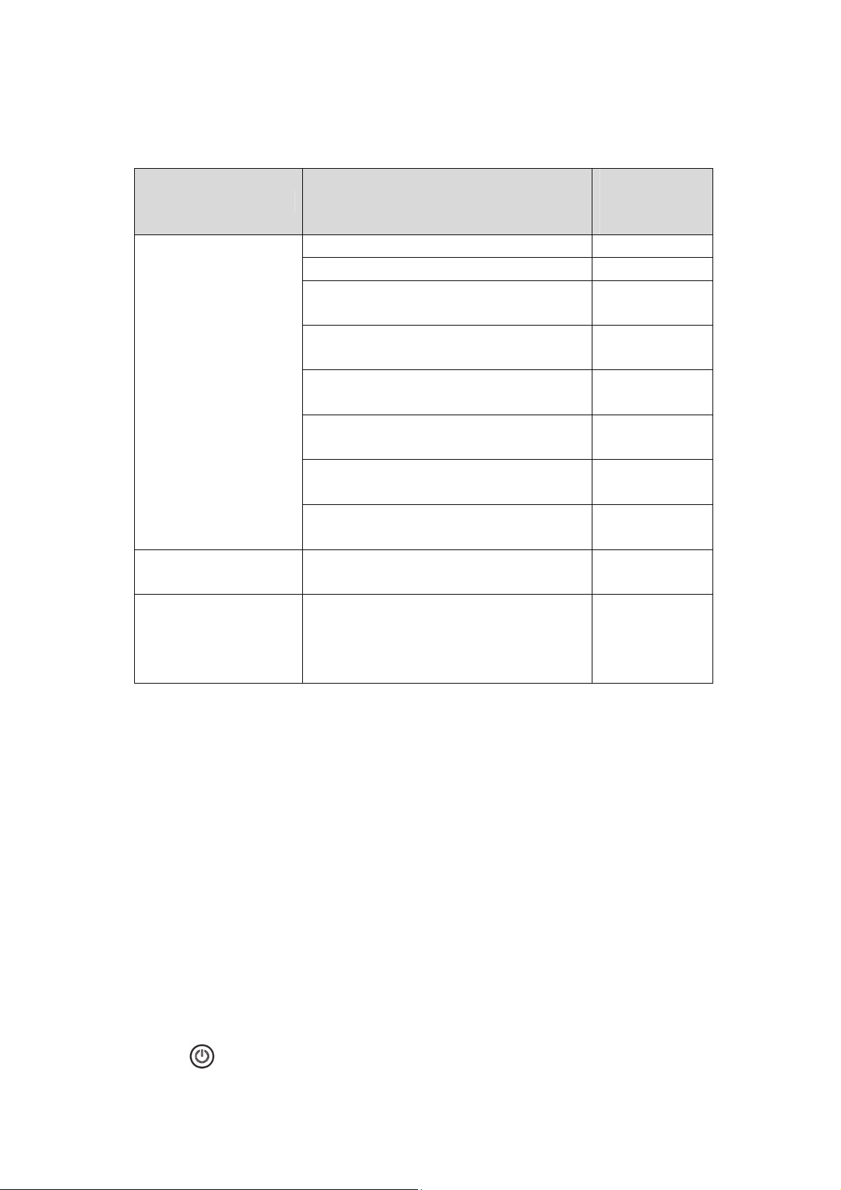
Compatibility with Phottix Flashes/S tr obes/Flash Triggers
Support
Master Unit Slave Units
TTL&M Info
Transmission?
Phottix Odin TTL Receiver for Canon
Phottix Strato Receiver for Canon
Phottix Strato II Multi Receiver for
YES
NO
NO
Canon
Phottix Mitros+ Transceiver Flash for
YES
Canon ODIN RX Mode
Odin II Transmitter
Phottix Indra PPL500 Studio Light
Odin-C Mode
Phottix Indra 360 TTL Studio Light
YES
YES
Odin-C Mode
Phottix Indra PPL500 Studio Light
NO
Strato II Mode
Phottix Indra 360 TTL Studio Light
NO
Strato II Mode
Phottix Odin TTL
Transmitter for Canon
Odin II Receiver
YES
Phottix Mitros+
Transceiver Flash for
Canon ODIN TX
Odin II Receiver
YES
Mode
Note:
1) Set the master unit and slave units to the same channel and corresponding
groups.
2) Strato receiver comes without group selection. It can be triggered by any
group of Odin II transmitter at the same channel.
3) When using Odin II transmitter with Strato/ Strato II Multi receiver, the flash
attached to the receiver has to be set to Manual mode.
4) When using Odin II transmitter with Strato/ Strato II Multi receiver in HSS
mode, the flash may not be able to sync.
5) Strato and Strato II Multi transmitter cannot trigger a Odin II receiver.
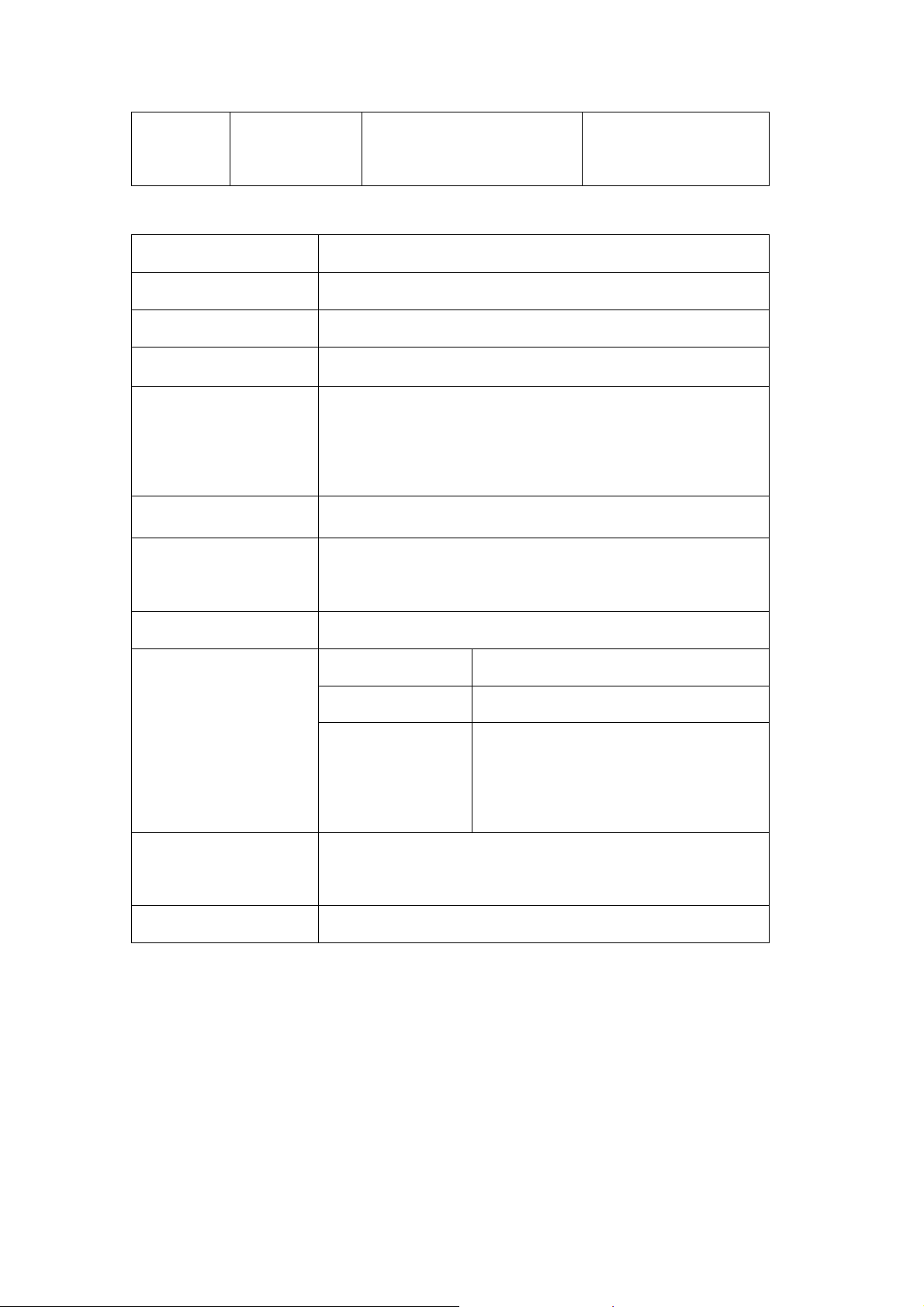
V.C.Fn: Setting the Custom Function
Odin II transmitter comes with a number of programmable custom functions. To edit
those functions, see below:
1. Press
to display the custom function screen.
Page 13
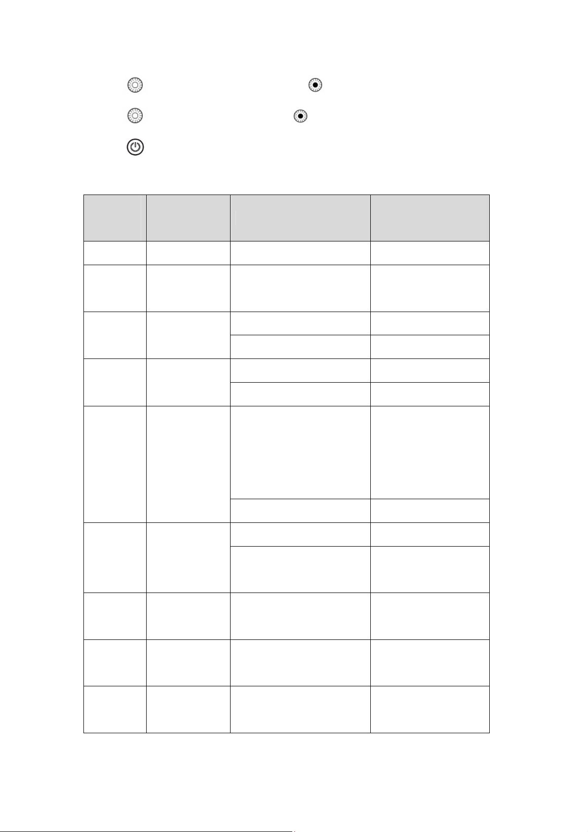
2. Turn to select an item to set and press button.
3. Turn to select the setting and press to confirm the setting.
4. Press to exit the custom function setting screen.
Custom Functions Chart
Custom
Function
No.
Functions Setting No.
Setting and
Descriptions
01 CH 01-32 Channel setting
ID setting(channel
02 ID 0000-9999
5-32)
ON Enable beep function
03 BEEP
OFF Disable beep function
ON Enable AF assist light
04 A.F.
OFF disable AF assist light
ON
05 SLEEP
OFF Disable idle mode
ON Enable LCD backlight
B.G.LIGHT
06
OFF
07 ODS 0.0-5.0
±3 stops in 1/3-stop
08 TTL PREF
increments
09 LCD 1/5, 2/5, 3/5, 4/5, 5/5
Enable idle mode
when the transmitter
is not operated for 5
min.
Disable LCD
backlight
Delay time for high
speed
TTL personal
preference
LCD panel display
contrast
Page 14
10 RESET OK
VI.Technical Specification
Reset all the settings
on transmitter
Frequency
Distance
Channels
Groups
Power Supply
Max sync speed
Transmitter Current
Receiver Current
AF Assist Light
2.4 GHz
100m+
32channels
5 groups– A, B, C,D,E
2X AA type alkaline batteries or NI-MH batteries(TX
and RX),
5V DC on receiver(external power port)
1/8000 sec*
Standby Current≤30mA; Idle Current≤25mA; Max.
Operating Current≤60mA
Max. Operating Current≤60mA
Peak wavelength 650nm
Optical power
Spot diameter at
1m
Dimensions
Weight
Note: Product specifications and external design are subject to change without further
notice.
*For compatible camera and flashes
(L109.3) x (W 71.7) x (H 56.0) mm(TX),
(L 81.8) x (W 69.3) x (H 47.6) mm (RX)
128.4g(TX)91.6g(RX)-Excluding the batteries
<5mW
Injecting distance 1m:
L-335mm W-326mm(angle of the
sector at approx.20º)
VII. Warnings
1. This product is a precise electronic instrument. Do not expose to damp
environments or dust.
Page 15

2. Please shut down the power of all devices when installing the wireless trigger.
3. Do not drop or crush.
4. Do not use the wireless trigger at flammable, explosive or high temperature
environment.
5. Do not use harsh chemicals or solvents to clean the body. Use a soft cloth or lens
paper.
6. Remove batteries from the wireless trigger if not being used for an extended
period.
7. Interference: The flash trigger transmits radio signals at 2.4GHz. Its performance
can be affected by electrical current, magnetic fields, radio signals, wireless
routers, cellular phones, and other electronic devices. Environmental objects, such
as large buildings or walls, trees, fences, or cars can also affect transmission
performance. If your wireless trigger can’t be triggered, move its location slightly.
 Loading...