


|
|
|
|
|
|
|
|
|
|
En |
INSTRUCTION MANUAL |
|
|||
|
|
|
|
Odin II TTL Flash Trigger
for Canon
|
|
|
|
|
|
|
|
|
|
|
|
|
|
|
|
|
|
|
|
En |
|
INSTRUCTION MANUAL |
|
|
|
|
|
|
|
|
|
|
|
|
|
|
|
|
|
|
|
|
|
||
|
|
|
|
|
|
|
|
|
|
|
|
|
|
|
|
|
|
|
|
|
||
|
|
|
|
|
|
|
|
|
|
|
|
|
|
|
|
|
|
|
|
|
||
|
|
|
|
|
|
|
|
|
|
|
|
|
|
|
|
|
|
|
|
|
||
|
|
|
|
|
|
|
|
|
|
|
|
|
|
|
|
|
|
|
|
|
||
|
|
|
|
|
|
|
|
|
|
|
|
|
|
|
|
|
|
|
|
|
||
|
|
|
|
|
|
|
|
|
|
|
|
|
|
|
|
|
|
|
|
|
||
|
|
|
|
|
|
|
|
|
|
|
|
|
|
|
|
|
|
|
|
|
||
|
|
|
|
|
|
|
|
|
|
|
|
|
|
|
|
|
|
|
|
|
||
|
|
|
|
|
|
|
|
|
|
|
|
|
|
|
|
|
|
|
|
|
||
|
|
|
|
|
|
|
|
|
|
|
|
|
|
|
|
|
|
|
|
|
||
|
|
|
|
|
|
|
|
|
|
|
|
|
|
|
|
|
|
|
|
|
||
|
|
|
|
|
|
|
|
|
|
|
|
|
|
|
|
|
|
|
|
|
||
|
|
|
|
|
|
|
|
|
|
|
|
|
|
|
|
|
|
|
|
|
||
|
|
|
|
|
|
|
|
|
|
|
|
|
|
|
|
|
|
|
|
|
||
|
|
|
|
|
|
|
|
|
|
|
|
|
|
|
|
|
|
|
|
Cn Simp |
|
|
|
|
|
|
|
|
|
|
|
|
|
|
|
|
|
|
|
|
|
|
Cn Trad |
|
|
1
|
En |
INSTRUCTION MANUAL |
|
||
|
||
|
Thank you for purchasing a Phottix product |
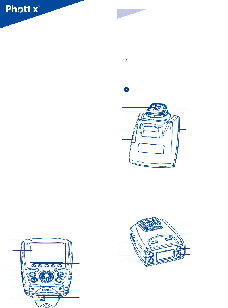
1. Status Light |
|
|
||
Before using the Odin II TTL flash trigger (for Canon) please read these |
2. LCD screen |
|
3. Zoom Button |
||
instructions carefully. Consult the manual of your camera and flash for setting |
4. Mode Button |
|
specific functions. |
5. Test button/Exposure Confirmation Indicator |
|
The Odin II TTL Flash Trigger – based on the award-winning Odin TTL Flash |
6. < |
>: Option/Confirm button |
Trigger. This new generation of TTL triggering keeps the core features of the |
7. Locking Ring |
|
original Odin system and adds two additional groups and 28 more channels, |
8. Flash Group Buttons (from left to right: A, B, C, D, E) |
|
Digital ID, AF Assist Illuminator and remote control of the Phottix Indra’s |
9. Power / Menu button |
|
modeling light. Other improvements include a more intuitive UI and increased |
10. High Speed Sync button(HSS) |
|
resistance to interference. |
11. Modeling Light Button |
|
This product is designed to work with Phottix and Canon ETTL/II hot shoe |
12. < |
>: Control Dial |
flashes. Please read these instructions carefully before usage. |
13. Lock Release Button |
|
|
14 |
18 |
|
15 |
|
|
|
|
Content |
|
Parts…...........................................................................…...2 |
|
Before using…................................................................…...3 |
|
Display content .................................................................... |
4 |
Functions and Operations..................................................... |
4 |
Menu Functions .................................................................... |
7 |
Technical specifications ........................................................ |
7 |
Warning ................................................................................ |
7 |
16
17
14.Hot Shoe Contacts
15.Locking Pin
16.AF Assist Light
17.Battery Compartment
18.Hot Shoe
19.USB port
Receiver
Parts
TCU
1 |
|
1 |
|
|
|
||
2 |
|
2 |
|
|
|
||
|
8 |
3 |
|
|
|
||
3 |
9 |
1. Power Button |
|
4 |
10 |
2. Channel/Option Button+ |
|
5 |
11 |
3. Flash/Option Button - |
|
6 |
|
4. Hot Shoe |
|
12 |
5. LED Indicator |
||
|
|||
7 |
13 |
6. Test Button |
|
7. ID/Forward Button |
|||
|
|
||
|
|
8. Enter button |
|
|
|
9. LCD Screen |
2
19
4
5
6
7
8
 9
9

10 |
13 |
14 |
|
|
15 |
11
12
16
10.Lanyard Attachment
11.Locking Ring
12.Cold Shoe/ ¼”x20 threaded lug
13.3.5mm Sync Port
14.USB Port
15.5V DC Port
16.Battery Compartment
En |
INSTRUCTION MANUAL |
Connecting the Odin II TCU to the Camera Hot Shoe
1.Turn OFF the camera and Odin II TCU
2.Slide the Odin TCU into the camera’s hot shoe mount.
3.Slide the Locking Ring to the right until a ’click’is heard, making sure the TCU is locked in position.
4.Turn ON the camera and TCU.
Disconnecting the Odin II TCU from the Camera Hot Shoe
1.Turn OFF the camera and Odin II TCU
2.Lock release: Press and hold the Lock Release Button on the Locking Ring, and slide the Locking Ring to the left.
3.Slide the Odin II TCU from the camera hot shoe.
Before using
Please Note:
1.When using Phottix Odin II TCU and Receiver the flash on the receiver must be in ETTL mode. It does NOT need to be in slave mode. The Odin II system will not work properly if the flash is set in slave mode.
2.Be sure to use the foot locking mechanisms to ensure a secure connection between Odin II TCU and the camera hot shoe, as well as the Odin II Receiver and the flash.
3.When connecting and disconnecting from camera, please switch off the power to all devices including flash, studio lights, camera, Odin II TCU and Receivers.
4.Although many brands and models of flash units have been tested with
the Phottix Odin II, there is no guarantee all third-party TTL flashes will work correctly. This product is optimized to work with Phottix and Canon ETTL/II hot shoe flashes, and the Phottix Indra TTL Studio Light series.
Inserting batteries
1.Push the Battery Cover on the Odin II TCU or Receiver in the direction indicated by the arrows on the Battery Cover to slide it open.
2.Insert the batteries according to markings in the battery compartment
3.Close the Battery Cover and push back into the locked position
4.When TCU and Receiver LCD Screens display the low battery symbol (below), replace the batteries.
TCU low battery indicator: Receiver low battery indicator:
Please Note
The Odin circuitry is designed to be used with either Alkaline, Ni-CD or NiMH rechargeable batteries. Do not use Lithium AA batteries in these units.
Turning the TCU and Receiver ON/OFF
Turn ON: Press and hold the power button until the LCD Screen displays the menu.
Turn OFF: Press and hold the power button until the LCD Screen goes blank.
Connecting a flash to the Odin II Receiver hot shoe
1.Turn OFF the flash and the Phottix Odin II Receiver.
2.Slide the flash into the receiver’s hot shoe mount.
3.Lock the flash with the flash’s locking mechanism.
4.Turn ON the flash and the Phottix Odin II receiver.
Disconnecting a flash from the Odin II Receiver hot shoe
1.Turn OFF the flash and the Phottix Odin II Receiver.
2.Unlock the flash with the flash’s locking mechanism.
3.Slide the flash from the Receiver’s hot shoe mount.
4.Turn ON the flash and the Phottix Odin II receiver.
Connecting the Odin II Receiver to Flash or Studio Light by cable
1.Turn OFF the flash/studio light and the Phottix Odin II receiver.
2.Insert the one end of the 3.5mm Cable to the Receiver’s 3.5mm port.
3.Connect the other end of the 3.5mm Cable to the Flash/Studio light. (A 6.3 mm adapter is included for studio strobes with larger ports).
4.Turn ON the flash / Studio light and Odin II Receiver.
5.Set the flash in Manual mode (if required) – no TTL functions can be used when a compatible flash is triggered by cable.
Please Note:
The Flash may fire when the receiver is turned on.
Flash Groups, Channels and ID setting
The Phottix Odin II System has:
•5flashgroups:A,B,C,DandE;
•32transmissionchannels;
•Digital ID Setting with 0000-9999 settings available.
Receivers can be assigned to a group, a channel and an ID at the same time. The TCU can adjust the EV, Power Levels and Zoom for each group (A, B, C, D,
3
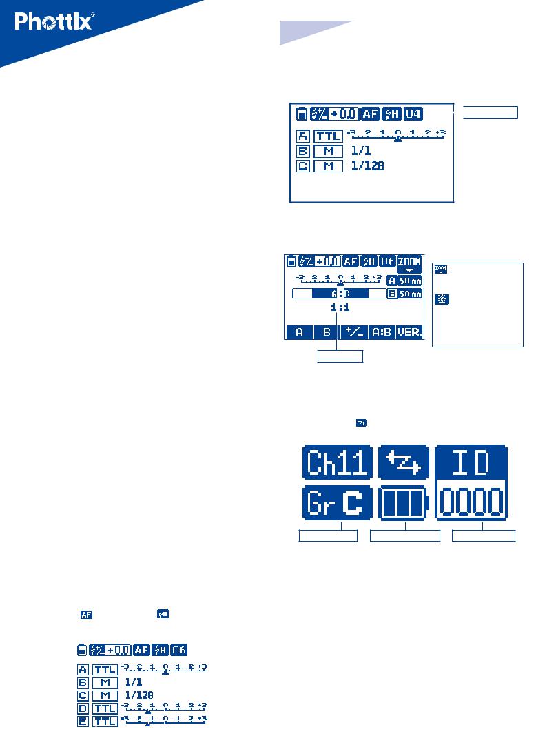
E) of receivers which are set to the same channel, and have the same Digital ID setting. (Unless the group is set to OFF on the TCU).
Adjusting Channel, Group and Digital ID on the TCU
The channel, group and ID number of the TCU can be set in Odin II Menu. Please see menu functions below.
Adjusting Channel, Group and Digital ID on the Receiver
1.To set Channels on the Receiver
2.Press  button, when the channel indicator on the LCD screen flashes.
3.Press or
or button to set the channel.
4.Press button to exit.
To set Group setting on the Receiver
1.Press button, when the group indicator on the LCD screen flashes.
2.Press selection button or
or to set group.
3.Press button to exit.
To set the Digital ID number on the Receiver
1.Press button.
2.Press selection button or
or  to adjust the ID value.
3.Press the ID (insert graphic) button to advance to the next digit.
4.Repeat until a four digit code is set.
5.Press to exit setting mode
Please note: When the Odin II is set to channels (1,2,3,4) it is compatible with Odin I receivers and Mitros+ flashes. When set to these channels the Odin II TCU will only control group A, B and C (like the Odin I TCU). Group D and E will not be displayed on the TCU and the Digital ID Function cannot be used.
En INSTRUCTION MANUAL
The Mixed TTL/M Mode(channels 1-4):
 Channel: 01~04
Ratio mode
 : ZOOM Level Adjustment in active (20-200mm)
: Modeling Light Adjustment in active (0-9) Blank: Zoom Level/ Modeling Light Adjustment Inactivated
Flash Ratio
Receiver
|
|
|
Flash and Receiver Communication |
|
|
|
|
|
|
|
In Communication |
|
Digital ID: |
||
Channel: 01-32 |
|
Blank: Out of communication |
|
0000~9999 |
|||
|
|
|
|
|
|
|
|
Display
TCU
The TCU has two operating modes: Mixed TTL/M mode and Ratio mode.
The Mixed TTL/M Mode (channels 5-32):
|
|
|
|
|
|
7.AF Asist Light: |
|
|
|
|
|
High Speed Sync |
|
|
|
|||||
|
|
|
|
|
|
: Enabled |
|
|
|
|
|
|
: Enabled |
|
|
|
||||
|
|
|
|
|
|
Blank: Disabled |
|
|
|
|
|
Blank: Disabled |
|
|
|
|||||
Flash Exposure |
|
|
|
|
|
|
|
|
|
|
||||||||||
Compensation |
|
|
|
|
|
|
|
|
|
|
|
|
|
|
|
Channel: 05~32 |
||||
|
|
|
|
|
|
|
|
|
|
|
|
|
|
|
|
|
|
|
|
|
Battery Level |
|
|
|
|
|
|
|
|
|
|
|
|
|
|
|
|
|
|
||
|
|
|
|
|
|
|
|
|
|
|
|
|
|
|
|
|
|
|||
Display |
|
|
|
|
|
|
|
|
|
|
|
|
|
|
|
|
|
|
||
|
|
|
|
|
|
|
|
|
|
|
|
|
|
|
|
|
|
|
|
|
|
|
|
|
|
|
|
|
|
|
|
|
|
|
|
|
|
|
|
|
Flash Output |
|
|
|
|
|
|
|
|
|
|
|
|
|
|
|
|
|
|
|
|
|
|
|
|
|
|
|
|
|
|
|
|
|
|
|
|
|
|
|
|
|
|
|
|
|
|
|
|
|
|
|
|
|
|
|
|
|
|
|
|
|
|
|
|
Groups |
|
|
|
|
|
|
|
|
|
|
|
|
|
|
|
|
|
|
|
|
|
|
|
|
|
|
|
|
|
|
|
|
|
|
|
|
|
|
|
|
|
|
|
|
|
|
|
|
|
|
|
|
|
|
|
|
|
|
|
|
|
|
|
|
|
|
|
|
|
|
|
|
|
|
|
|
|
|
|
|||
|
|
|
|
|
Flash |
Mode : |
|
Flash Exposure |
|
|||||||||||
|
|
|
|
|
TTL, M, OFF |
|
|
Compensation |
|
|||||||||||
|
|
|
|
|
|
|
|
|
|
|
|
|
|
|
|
|
|
|
|
|
4
Group: A, B,C,D,E |
Battery Level Display |
Digital ID selected |
Functions and Operations
TCU Modes
In Mixed TTL/M mode groups A/B/C/D/E can be set to TTL, Manual (M) or Turned-Off. EV or power levels can also be adjusted.
The ratio mode is similar to the original Canon TTL system, The ratio of groups A and B can be set from 8:1 to 1:8. EV levels can also be adjusted.
Setting the Operating Mode
Press button of the TCU to change between Mixed TTL/M mode and Ratio mode.

|
En |
INSTRUCTION MANUAL |
|
||
|
||
|
The Mixed TTL/M mode Setting Flash Mode
Press Flash Group Button that needs to be adjusted.
Press button to select the operating mode for flash group and press the
  button on the TCU to confirm: There are TTL, manual (M) and off mode.
TTL Mode: When using TTL metering to fire flashes, the EV level can be adjusted from -3EV to +3 EV in increment of 1/3 stops. TTL exposures often require fine-tuning – EV adjustments allow you to tailor the TTL exposure to the environment and your shooting style.
Manual (M) Mode: The flash will operate as it does when set to manual mode and the power levels can be adjusted from 1/1 and 1/128 in 1/3 stops increments.
Off mode: Will turn off the selected group. Flashes in this group will not fire. LCD display will not display the group unless the corresponding group button is pressed and it will display‘off’on the screen
Adjusting EV / Power Level
1.Press flash group button that requires adjustment.
2.Turn  to set the EV or power level for the selected group.
3.After setting, press the  button on the TCU to exit adjustment mode.
Ratio Mode Adjustments
1.Press the corresponding flash group button  , located under the
  symbol on the LCD Screen.
2.Turn  to set the light ratio from 8:1 to 1:8 in increment of 1/2 stops.
3.After setting, Press the  button on TCU to exit setting mode.
4.Current setting information will be saved on the TCU.
Status Light function
1.The Status Light on the TCU and Receiver flash green when they are in idle mode.
2.When focusing, the Status Light on the TCU and receiver will turn solid Green.
3.When taking photos, the Status Light will turn red.
Modeling Light Button
This Modeling Light Button is designed to work with the modeling light on the Phottix Indra Studio Light series. The Indra Modeling Light brightness can be adjusted from 0-9 with the Odin II TCU.
1.Press  button to enter Modeling Light Adjustment Mode.
2.Press the Flash Group Button of the group to be adjusted.
3.Turn  to adjust the brightness level of the modeling light of the group.
Repeat the operation to adjust other groups. Modeling light brightness in Groups A-E can be set for each group.
4. Press  button to finish setting and exit setting mode.
Note: This function is not available for on-camera flash.
The Odin will return to main menu after 8 seconds if the modeling light adjustments are not made.
LCD backlight
Pressing any button on the TCU or the Receiver will turn on the LCD Backlight. It will stay ON for approximately 10 seconds. If no further buttons are pressed, the Backlight will go off. The LCD Backlight of the TCU can be set to ON or OFF in the TCU Menu Screen (see below).
Test Button/Exposure Confirmation Indicator( 
1.Pressing the TEST button will fire all flashes mounted on or wire-connected to Receivers that are on the same channel, group and ID as the TCU. All the flashes of group A, B,C, D and E will be triggered simultaneously.
2.When the TCU is in IDLE mode the Exposure Confirmation Indicator will appear red. When focusing or when the camera is communicating the Indicator will turn off. After pressing the shutter to take photos, the indicator will appear green and remain illuminated. When the indicator appears green or off, pressing it cannot fire the flash being controlled by the Odin TCU
3.If group A,B,C,D,E are selected to manual mode, pressing the test button
will result in all flashes mounted on receivers (same channels and digital ID as the TCU) to fire a low power preflash. After 2.5s the flashes will fire at the
selected power level on TCU. A light meter can be used after the initial preflash if desired.
Adjusting flash zoom
The Odin II TCU allows the zoom level of remote hot shoe flashes to be set. Zoom can be set in Auto or Manual mode.
Auto Zoom Mode: The flash zoom will change dynamically as the camera zoom ring is adjusted.
Manual Zoom Mode: The flash zoom can be set to a fixed value. The flash zoom will not change with the adjustment of the camera lens focal length.
To set flash zoom with the Odin II TCU
1.Set the zoom function of the flash on an Odin II Receiver to Auto or AZoom.
2.Setting Odin II TCU.
1)Press the Zoom Button and enter to the Flash Zoom Adjustment Screen.
2)Press Flash Group Button for the group to be adjusted.
3)Turn the  and set the zoom mode to Auto, or adjust the zoom to a manual value (20-200mm).
4)Repeat to adjust the zoom setting.
5)Press  to exit.
Please note:
Unlike the Odin I system, there is no auto zoom feature. Flash zoom must be adjusted manually, it will not change as lens focal distance is changed.
The Odin is only able to adjust the existing zoom specifications of the flash. The Odin does a lot of things, but it cannot make a flash with a maximum zoom of 135mm zoom to 200mm.
The Odin will return to main menu if left idle in the zoom adjustment screen for 8 seconds.
5

Flash Exposure Compensation: FEC
Odin II allows flash exposure compensation to be set for all groups from -3EV to +3EV in increment of 1/3 stops. FEC allows you to use more or less light as required for proper exposure or special effects.
To Set:
1.In TTL/M mixed mode :
1)Press button and enter to the Flash Exposure Compensation Adjustment Screen.
2)Turn  to set the Flash Exposure Compensation.
3)Press  button to exit.
2.In Ratio mode:
1)Press the corresponding flash group button  under the
  symbol on the LCD Screen.
2)Turn  to set the the Flash Exposure Compensation.
3)Press  Confirm button to exit.
High Speed Sync (HSS)(  )
)
HSS function enables flash sync speeds of up to 1/8000 sec. HSS can only be used with cameras and flashes which support this function.
1.Press  button to enable the HSS function. The
  icon will appear on the LCD Screen.
2.Shutter speeds above the camera X-Sync speed will now be available. Adjust the camera shutter speed.
3.Press  button again to disable HSS mode. The
  icon will disappear from the LCD Screen.
High Speed Burst Function
When using Odin II, flash burst speed (with a remote flash) might be slower than with a flash in the camera’s hot shoe. Please set this function in your camera. For setting details, please consult the manual of your camera.
Built-in AF assist illuminator
The Odin II TCU features a built-in AF Assist illuminator for use in low light / low contrast conditions. The AF Assist will project a focusing target allowing for easier focus in many situations. This Illuminator can be set to ON or OFF in the Odin II Menu (see below).
Note: The Odin II TCU uses an eye-safe laser light with beam power less than 5mW. For safety, use precautions when using the AF Assist Illuminator, and avoid shining directly into subjects’eyes.
Second Curtain Sync (Rear Curtain Sync)
Unlike the Odin 1 and 1.5 systems for Canon, the Odin II for Canon does not offer Second Curtain Sync or Rear Curtain Sync fucntions
ODS Function
The Odin II TCU is capable of adjusting flash triggering times to enable shooting at higher sync speeds with some studio flashes (especially those with
6
En |
INSTRUCTION MANUAL |
IGBT circuitry). The ODS (OverDrive Sync) mode allows delaying and advancing the flash trigger point to optimized flash exposure for high shutter speeds with various flash and camera combinations. The ODS setting is made in the Odin II’s Menu.
Note:
Reset the ODS value to default when not being used.
Compatibility with Phottix Series flashes / triggers
Transmitter |
Receiver |
TTL& |
|
M Control |
|||
|
|
||
|
Phottix Odin TTL Receiver Canon Version |
Yes |
|
|
Phottix Strato Receiver Canon, Nikon, Sony Versions |
No |
|
|
Phottix Strato II Multi Receiver (Canon, Nikon, Sony Versions) |
No |
|
|
Phottix Mitros+ Transceiver Flash Canon Version |
Yes |
|
|
ODIN RX mode |
||
|
|
||
Odin II TCU |
Phottix Indra500 TTL Studio Light Odin-C mode |
Yes |
|
|
Phottix Indra360 TTL Studio Light Odin-C Mode |
Yes |
|
|
Phottix Indra500 TTL Studio Light Strato II Mode |
No |
|
|
Phottix Indra360 TTL Studio Light Strato II Mode |
No |
|
Phottix Odin TTL |
Odin II Receiver |
Yes |
|
TCU Canon Version |
Odin II Receiver |
||
Phottix Mitros+ |
Flash Exposure |
Yes |
|
Transceiver Flash(Canon |
|||
Compensation |
|||
Version) ODIN TX Mode |
|
|
Note:
1.The channel and group on the receiver should match that set on the TCU.
2.The Strato Receiver can be triggered by Odin II TCU on the same channel. Group settings cannot be used.
3.When using Odin II TCU and Strato / Strato II Multi receiver, the flash mounted on the remote receiver needs to be set in Manual mode.
4.Using the Odin II TCU in high speed sync mode with Strato / Strato II Multi receiver may cause the flashes to be out of sync.
5.Strato and Strato II Multi Transmitters can not trigger Odin II or Odin 1 receivers.
6.High speed sync is not supported while using the Odin II TCU with Strato/ Strato II receivers
Upgrading firmware by USB
The firmware of the TCU and receivers can be upgraded using the included USB cable. Any upgrades and full instructions will be announced on the Phottix Blog (journal.phottix.com).
Viewing Hardware/Software Version Data on TCU:
1.Press button to enter ratio mode interface.
2.Press the corresponding flash group button  under the
  symbol on the LCD Screen.
3.Version details will be shown.
Viewing Hardware/Software Version on the Receiver:
1. With the reciver is powred off, press and hold button and power button for 2s. The Hardware/Software versions will be displayed on the LCD. Press any button to proceed to main screen.
 Loading...