

Page 1
P5A/6A/8A
PROFESSIONAL STUDIO MONITOR
MONITOR DE ESTUDIO PROFESIONAL
专业录音室监听音箱
P8A
User’s Manual
Manual del Usuario
使用手册
English / Español / 简体中文
Page 2
P5A/6A/8A
PROFESSIONAL STUDIO MONITOR
MONITOR DE ESTUDIO PROFESIONAL
专业录音室监听音箱
CONTENTS
INTRODUCTION......................................4
DRIVERS..........................................4
CROSSOVER...................................4
AMPLIFIER.......................................4
FEATURES...............................................5
INSTALLATION........................................5
SETING THE INPUT SENSITIVITY...5
SETTING TONE CONTROL.............5
LOW MAT C H .................6
ROOM COMPENSAT I O N . . 6
HIGH MAT C H . . . . . . . . . . . . . . . . . . 6
CONTENIDO
INTRODUCCIÓN...............................................10
DRIVERS..................................................10
CROSSOVER............................................10
AMPLIFICADOR........................................10
CARACTERÍSTICAS........................................11
INSTALACIÓN..................................................11
SETEO DE SENSIBILIDAD DE ENTRADA.11
SETEO DE CONTROL DE TONO.............11
BAJO MATCH....................................12
COMPENSACIÓN DE CUARTO..12
ALTO MATCH....................................12
目录
简介 ... . . . . . . . . ....... . . . . . . . . ....16
单体................. . . . . . . . . 1 6
分频器......................16
功率放 大 器 .... . . . . . . . . . . . . 1 6
特色 ... . . . . . . . . ....... . . . . . . . . ....16
准备 工 作 . . . ..... . . . . . ..... . . . . . .17
设定 输 入 灵 敏 度 . ........ . 1 7
设定 音 调 控 制 . . . . . . . ......17
低频 匹 配 . . ...... . . . . . 17
室内 补 偿 . . ...... . . . . . 17
高频 匹 配 . . ...... . . . . . 17
POWER MO D E ..............6
INPUT C O N N E C TORS.....6
MOUNTING THE MONITOR....................7
VERTICAL/HORIZONTAL MOUNTING..7
CONSOLE TOP MOUNTING ..........7
OVERLOAD INDICATOR.........................7
SPECIFICATIONS....................................8
MONTANDO EL MONITOR..............................13
INDICADOR DE SOBRECARGA.....................13
ESPECIFICACIONES.......................................14
MODO DE ENERGÍA........................12
CONECTORES DE ENTRADA..........12
MONTAJE VERTICAL / HORIZONTAL........
MONTAJE SUPERIOR DE CONSOLA...13
.13
电源模 式 ........ . . . . ..17
输入 连 接 . . ...... . . . . . 17
安 装 监 听 喇 叭 . . . . .... . . . . .... . . 1 8
垂 直 / 水 平 放 置 . .. . .. .. . . 18
混 音 控 制 台 安 装 . . . .. . . .. 1 8
过 载 指 示 器 . . . .. . .. . . .. . . .. . . .. 1 8
规 格 . . .. . . .. . . . ... . . ... . . ... . . ... 1 9
Phonic preserves the right to improve or alter any information within this document without prior notice
Phonic se reserva el derecho de mejorar o alterar cualquier información provista dentro de este documento sin previo aviso
PHONIC保留不预先通知便可改变或更新本文件权利
V1.0 11/14/2008
Page 3
1. Read these instructions before operating this
apparatus.
2. Keep these instructions for future reference.
3. Heed all warnings to ensure safe operation.
4. Follow all instructions provided in this document.
5. Do not use this apparatus near water or in locations
where condensation may occur.
6. Clean only with dry cloth. Do not use aerosol or liquid
cleaners. Unplug this apparatus before cleaning.
7. Do not block any of the ventilation openings. Install
in accordance with the manufacturer’s instructions.
8. Do not install near any heat sources such as radiators,
heat registers, stoves, or other apparatus (including
.
9. Do not defeat the safety purpose of the polarized or
grounding-type plug. A polarized plug has two blades
with one wider than the other. A grounding type plug
has two blades and a third grounding prong. The wide
blade or the third prong is provided for your safety. If
the provided plug does not into your outlet, consult
an electrician for replacement of the obsolete outlet.
10. Protect the power cord from being walked on or
pinched particularly at plug, convenience receptacles,
and the point where they exit from the apparatus.
11. Only use attachments/accessories by the
manufacturer.
12. Use only with a cart, stand, tripod, bracket, or
table by the manufacturer, or sold with
the apparatus. When a cart is used, use caution
when moving the cart/apparatus
combination to avoid injury from tipover.
13. Unplug this apparatus during lighting
storms or when unu sed for long
periods of time.
14. Refer all servicing to service personnel.
Servicing is required when the apparatus has been
damaged in any way, such as power-supply cord or
plug is damaged, liquid has been spilled or objects
have fallen into the apparatus, the apparatus has
been exposed to rain or moisture, does not operate
normally, or has been dropped.
IMPORTANT SAFETY INSTRUCTIONS
CAUTION: TO REDUCE THE RISK OF ELECTRIC SHOCK,
DO NOT REMOVE COVER (OR BACK)
NO USER SERVICEABLE PARTS INSIDE
REFER SERVICING TO QUALIFIED PERSONNEL
The lightning flash with arrowhead symbol, within an
equilateral triangle, is intended to alert the user to the
presence of uninsulated “dangerous voltage” within the
product
’
magnitude to constitute a risk of electric shock to persons.
The exclamation point within an equilateral triangle is in-
tended to alert the user to the presence of important operat-
ing and maintenance (servicing) instructions in the literature
accompanying the appliance.
WARNING: To reduce the risk of or electric shock, do
not expose this apparatus to rain or moisture.
CAUTION: Use of controls or adjustments or performance
of procedures other than those may result in
hazardous radiation exposure.
The apparatus shall not be exposed to dripping or splashing and that no objects with liquids, such as vases,
shall be placed on the apparatus. The MAINS plug is used as the disconnect device, the disconnect device shall
remain readily operable.
Warning: the user shall not place this apparatus in the area during the operation so that the mains switch
can be easily accessible.
CAUTION
RISK OF ELECTRIC SHOCK
DO NOT OPEN
Page 4

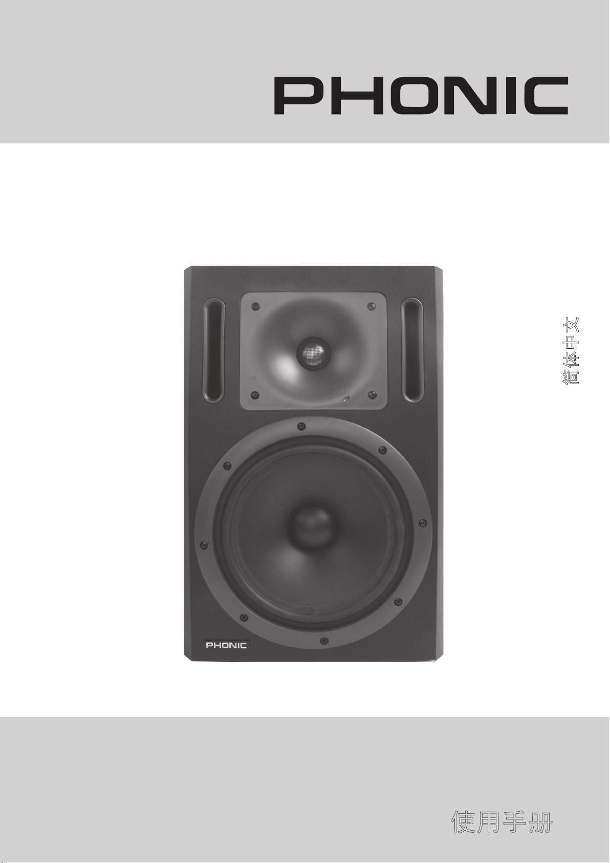
INTRODUCTION
The bi-amplified P5A/6A/8A are two-way active
monitoring speakers designed for high output, low
coloration and broad bandwidth. P5A is 5” 2-way; P6A
is 61/4” 2-way, P8A is 83/4” 2-way. Bigger number
means bigger power as well as bigger woofer, which
offers extended low frequency response and higher
output level.
Due to its compact size, integrated construction,
excellent dispersion and precise stereo imaging,
this speaker system is ideal for near eld monitoring, mobile vans, broadcast, TV control rooms and
home studios.
Designed as an active speaker, this unit contains
drivers, power ampliers, active crossover ltering
and protection circuitry. The directivity control system
used provides excellent frequency balance even in
difcult acoustic environments.
SOFT DOME WITH SOUND GUIDING HORN
This horn is designed to provide better sound directivity for the listener(s). With its smooth surface and
well-spread angle, the sound produced from the
tweeter can be easily forwarded to the listener(s).
DRIVERS
The bass frequency is reproduced by a 5-inch, 61/4”inch, and 83/4” -inch woofer respectively. P5A, P6A,
and P8A all use a 25mm (1 inch) soft dome tweeter,
with pure piston behavior up to 20KHz. The uniform
dispersion control is achieved with the directivity control system. This has also resulted in perfect phase
and delay uniformity at thecrossover frequency. Both
drivers in PSeries Active Version are magnetically
shielded. Please feel free to place this unit next to
your PC, laptop, or any other electronic devices.
CROSSOVER
The active crossover network consists of two par-
allel band pass lters. Acoustically the lters are
complementary and the slopes are 24dB/ octave.
The crossover frequency is set to 1.8KHz. By use of
active crossover controls (Low Match, Room Compensation, and High Match, which will be introduced
on page 6), this speaker may be exactly matched to
any application.
AMPLIFIERS
The amplier unit is mounted to the rear panel of the
speaker with damping material, to ensure rattle free
operation and long term reliability. The unit incorporates special protection circuitry as well, for driver
overload protection and amplier thermal overload
protection. Variable input sensitivity allows for accurate level matching to the mixing console.
4 P5A / P6A / P8A
Page 5

FEATURES
INSTALLATION
P5A 5” 2-way active studio monitor
P6A 61/4” 2-way active studio monitor
P8A 83/4” 2-way active studio monitor
● Unique linear phase and frequency response
● Soft dome with sound guiding horn
● Superb sonic accuracy
● Bi-amplied circuitry design
● Active crossover with 4th order Linkwitz-Riley
lters
● Bi-color power on & overload protection indica-
tor
● Power on muting circuitry
● Thermal protection
● Two built-in limiters for high-frquency and low-
frequency output
● HIGH MATCH control for compensating HF (tweeter) output with +2, 0, -2, or -4dB selection
● Variable ROOM COMPENSATION with +/- 6dB
range for location matching
● LOW MATCH control (high pass lter) for using
with subwoofer
● High grade MDF wooden enclosure
● Precision bass port tuning
● Internal damping for minimum cabinet reso-
nance
● Magnetically shielded
● XLR and 1/4” jacks for input
Each active studio monitor is supplied with an inte-
grated amplier unit, a mains cable and an operating
manual. Once unpacked, place the loudspeaker in its
required listening axis. Before connecting up, ensure
that the mains switch is off. Audio input is made via
a balanced (XLR) and 1/4” TRS phone jacks, which
are in paralell. But unbalanced leads may be used
as long as pin 3 is grounded to pin 1 of the XLR, or
linking Ring to sleeve of the 1/4” TRS phone jack.
Once connection has been made, the speakers are
ready to be powered-up. Before turning the unit on,
make sure the mains needed is identical with the
AC outlet.
SETTING THE INPUT SENSITIVITY
Adjustment of the input sensitivity of each speaker
can be made to match that of the mixing console or
other source, by using the input sensitivity control on
the rear panel. The manufacturer default setting for
this control is -6dBu (fully clockwise).
SETTING TONE CONTROL
The acoustic response of the system may also have
to be adjusted to match the acoustic environment.
The adjustment is done by setting the tone control
switches on the control panel of the amplier. Phonic’
s default settings for these controls are to give a at
anechoic response. Set switch to the desired position
to select response curve needed.
5P5A / P6A / P8A
Page 6

1. LOW MATCH
5
4. POWER MODE
This is a high pass lter. The numbers above the
switch tells you the crossover frequency points. While
use this unit with a subwoofer, you can select a suit-
able frequency to match the additional subwoofer.
2. ROOM COMPENSANTION
User can alter the output volume of woofer depending
on its setup position. Positioned real close against the
wall, this unit will have stronger low frequency. It is
necessary then, to set the level of the low frequency
output at -2dB to achieve the best balance between
high and low frequency. When located at the corner,
it is suggested to set this level at -4dB. Basically, the
longer distance your monitor is to the wall, the more
you need to boost this bass gain.
3. HIGH MATCH
Use this to adapt the speaker’ s frequency response
to the damping characteristics of the control room.
You can use this switch to select between “ON”,
“AUTO ON” , and “OFF” . When set to OFF, this unit
is compelety switched off and cannot be activated by
the power switch. When the switch is set to AUTO
ON, this unit will automatically operate as soon as
a signal is sent to its input. On the other hand, this
unit will automatically deactivate when the signal is
paused for more than ve minutes. When the switch
is set to ON, this unit is activated all the time and can
be turned off only by the power switch.
5. INPUT CONNECTORS
The balanced 1/4” and XLR inputs are available
for users to connect various ouput devices to the P
Series Studio Monitors.
6 P5A / P6A / P8A
Page 7

MOUNTING THE MONITOR
VERTICAL / HORIZONTAL MOUNTING
The speakers are normally delivered for vertical
mounting. Designed for neareld monitoring, this studio monitor requires shorter distance than traditional
monitors from its location to your ears, which means
the reverberation time and general acoustics of the
listening room are less critical. Hard surfaces will,
however, reect the higher frequencies, therefore try
to avoid putting this monitor close to side walls. The
control surface of your mixing console may also pose
a problem. To minimize control surface reections,
position your monitor as shown in the gure below,
using the meter bridge or rear panel to block sound
from both drivers reaching the control surface. Make
sure that there is nothing between your ears and the
speakers. If your console has no meter bridge, try
positioning the monitor higher or further behind the
desk. Active series is designed to be used in both the
upright and horizontal position. If you want to place
two Active series horizontally, it is recommended you
put the HF drivers on the outer edge. The low frequencies of this unit will generally sound better if the
cabinet is against a wall. If possible, provide a rigid
surface (eg.shelf) that is separate from the mixing
console and other equipment. The speakers should
roughly form a 60 degree angle at the listening position, and should be angled towards the listener(s).
CONSOLE TOP MOUNTING
If the active studio monitor series are used for console
top mounting, it is recommended not to mount the
speakers directly on the console; instead, position
the speaker slightly behind the console by using
oor stand or wall mount behind the console. This
prevents the reection from the console surface from
coloring the sound.
OVERLOAD INDICATOR
The speaker is provided with one bi-colored indicator on the bottom right corner of the horn. When lit
in green, it indicates that the speaker is ready for
use. The indicator lighting up in red means that the
amplier is overload or the driver protection circuit
is activated. In either cases, reduce the signal level
so that the red LED stops blinking. If the red indica-
tor stays on constantly, it means that the amplier
thermal protection is activated. Let the amplier
cool down and check that the ventilation at the rear
side of the speaker is not blocked. There should be
a clearance of more than 4 inches (10cm) between
speaker rear and any solid surface.
7P5A / P6A / P8A
Page 8

SPECIFICATIONS
P8A
212W / 106W
P6A
170W / 70W
x9.1”
231.1mm)
x
10.6”
x
269.2
x
22.0lbs(10kg)
16.9"
(249.3
x9.3”
236.2mm)
x
8.7”
On/Off
XLR, 1/4” TRS
Bi-color On/Peak
x
221.0
x
13.8"
18.0 lbs(8.2 kg)
P5A
140W / 70W
HIGH (Program)
Amplier LOW /
(337.3
1.8dB Hz, 24dB/oct Linkwitz-Riliey Filter
9.1”
231mm)
x
x
7.7”
Clip Limiter, Power On muting, Thermal and Overload Protection
x
195.6
x
Input Trim, High Match, Room Compensation, Low Match, Power On/Auto
Protection Circuit
Crossover
Indicator
Connection
Control
11.6"
Dimensions
12.9 lbs(5.6 kg)
(294.6
Net Weight
(H x W x D)
Specications are subject to change without prior notice.
8 P5A / P6A / P8A
Page 9

Page 10

INTRODUCCIÓN
Los P5A/6A/8A bi-amplicados son altavoces de monitoreo
activos de dos-vías diseñados para alto rendimiento, baja
coloración y amplio ancho de banda. P5A es de 5” 2-vías,
P6A es de 6 1/4” 2-vías, P8A es de 8 3/4” 2-vías. Un número
mayor signica una energía mayor así como un woofer más
grande, que ofrece respuesta de baja frecuencia extendida
y un nivel de salida más alto.
Debido a su tamaño compacto, construcción integrada,
excelente dispersión y proyección de imagen estérea
precisa, este sistema de altavoz es ideal para el monitoreo
del campo cercano, camioneta móviles, broadcast, sala de
mando de la TV y estudios caseros.
Diseñado como un altavoz activo, esta unidad contiene
controladores, amplicadores de potencia, ltración activa
de crossover y circuito de la protección. El sistema de
control de la directividad usado proporciona excelente
balance de la frecuencia incluso en ambientes acústicos
difíciles.
DOMO SUAVE CON HORN DE GUÍA DE
SONIDO
Este horn está diseñado para proporcionar una mejor
directividad de sonido para los oyentes. Con su supercie
lisa y ángulo bien-separado, el sonido producido desde
tweeter puede ser remitido fácilmente a los oyentes.
DRIVERS
La frecuencia baja es reproducida por woofer de
5-pulgadas, 6 1/4” –pulgadas y 8 3/4” –pulgadas
respectivamente. P5A, P6A, y P8A todos utilizan un tweeter
de domo suave de 25mm (1 pulgada), con comportamiento
puro del pistón hasta 20KHz. El control de la dispersión
uniforme es alcanzado con el sistema de control de
directividad. Esto también ha dado lugar a fase perfecta
y uniformidad del retardo en la frecuencia de crossover.
Ambos controladores en la Versión Activa de Serie P
son blindados magnéticamente. Por favor sienta libre de
colocar esta unidad al lado de su PC, del ordenador portátil,
o de cualquier otro dispositivo electrónico.
CROSSOVER
La red activa de crossover consiste de dos ltros del
paso de banda paralelos. Acústicamente los ltros son
complementarios y las pendientes son de 24dB/octava.
La frecuencia de crossover está seteada a 1.8KHz.
Por medio de controles activos de crossover (Bajo
Match, Compensación de Lugar y Alto Match, que serán
introducidos en la página 12), este altavoz se puede
adecuar exactamente a cualquier aplicación.
AMPLIFICADOR
La unidad del amplicador es montada al panel de dorso
del altavoz con material amortiguador, para asegurar la
operación libre de traqueteo y la conabilidad de largo
plazo. La unidad también incorpora circuito especial
de protección, para la protección de la sobrecarga del
controlador y la protección termal de la sobrecarga del
amplicador. La sensibilidad de entrada variable permite
que el nivel exacto corresponde a la consola de mezcla.
10 P5A / P6A / P8A
Page 11

CARACTERÍSTICAS
P5A Monitor de estudio activo de 5” 2-vías
P6A Monitor de estudio activo de 6 1/4” 2-vías
P8A Monitor de estudio activo de 8 3/4” 2-vías
Fase linear única y respuesta en frecuencia
Domo suave con horn de guía de sonido
Exactitud acústica magníca
Diseño bi-amplicado del circuito
Crossover activo con ltros Linkwitz-Riley de 4ta
orden
Indicador bicolor de encendido de energía &
protección de sobrecarga
Circuito de enmudecimiento de encendido de
energía
Protección termal
Dos limitadores integrados para la salida de alta-
frecuencia y de baja-frecuencia
Control de ALTO MATCH para compensar salida de
HF (tweeter) con selección de +2, 0, -2, o -4dB
COMPENSACIÓN DE LUGAR variable con rango
de +/-6dB para corresponder la localización
Control de BAJO MATCH (ltro de alto paso) para
usar con el subwoofer
Bocina de madera MDF del alto grado
Adaptación de puerto de bass de precisión
Amortiguación interna para la resonancia mínima
del gabinete
Blindado magnéticamente
INSTALACIÓN
Cada monitor del estudio activo es suministrado con una
unidad integrada del amplicador, cables principales y
un manual de operación. Una vez desempaquetado,
coloque el altavoz en su eje que escucha requerido. Antes
de conectar, asegúrese de que el interruptor principal
está apagado. La entrada de audio se hace vía (XLR)
balanceado y jacks de audífono de 1/4” TRS que están
en paralelo. Pero los conductores desbalanceados pueden
ser utilizados mientras el pin 3 se ponga a tierra a pin 1 de
XLR, o ligando el Ring a Sleeve de jack de audífono de 1/4”
TRS. Una vez que se ha hecho la conexión, los altavoces
están listos para ser accionados. Antes de encender la
unidad, cerciórese de que los cables principales necesarios
sean idénticos con el enchufe de AC.
SETEO DE SENSIBILIDAD DE ENTRADA
El ajuste de la sensibilidad de entrada de cada altavoz
puede ser hecho para emparejar la de consola de mezcla
o de otra fuente, usando el control de sensibilidad de la
entrada en el panel de dorso. El ajuste por defecto del
fabricante para este control es de -6dBu (completamente
a la derecha).
SETEO DE CONTROL DE TONO
La respuesta acústica del sistema puede también tener que
ser ajustada para adecuar al ambiente acústico. El ajuste
se hace ajustando los interruptores de control de tono en
el panel de control del amplicador. Los seteos por defecto
de Phonic para estos controles son para dar una respuesta
anecoica plana. Setee el interruptor a la posición deseada
para seleccionar la curva de respuesta necesaria.
Jacks XLR y 1/4” para entrada
11P5A / P6A / P8A
Page 12

1. BAJO MATCH
5
Este es un ltro de paso alto. Los números arriba del
interruptor le dice los puntos de la frecuencia de crossover.
Mientras utilice esta unidad con un subwoofer, usted puede
seleccionar una frecuencia conveniente para adecuar al
subwoofer adicional.
2. COMPENSACIÓN DE CUARTO
El usuario puede alterar el volumen de la salida de woofer
dependiendo de su posición de setup. Posicionado
realmente cerca contra la pared, esta unidad tendrá
frecuencia baja más fuerte. Entonces es necesario, jar el
nivel de la salida de baja frecuencia en -2dB para alcanzar
el mejor equilibrio entre frecuencua alta y baja. Cuando
está localizado en el rincón, se sugiere setear este nivel en
-4dB. Básicamente, mayor es la distancia de su monitor a la
pared, usted necesita alzar más esta ganancia de bajo.
3. ALTO MATCH
Utilice esto para adaptar la respuesta en frecuencia del
altavoz a las características de amortiguación del sala
de control.
4. MODO DE ENERGÍA
Usted puede utilizar este interruptor para seleccionar entre
"ON" (encendido), “AUTO ON” (encendido automático) y
"OFF"(apagado). Cuando setea a OFF, esta unidad es
apagada completamente y no puede ser activada por el
interruptor de energía. Cuando el interruptor está seteado
en AUTO ON, esta unidad funcionará automáticamente
tan pronto como una señal es enviada a su entrada. Por
otra parte, esta unidad desactivará automáticamente
cuando la señal se detiene por más de cinco minutos.
Cuando el interruptor está seteado a ON, esta unidad está
activada todo el tiempo y se puede apagar solamente por
el interruptor de energía.
5. CONECTORES DE ENTRADA
Las entradas balanceadas 1/4” y XLR están disponibles
para que los usuarios conecten los varios dispositivos de
salida a los Monitores del Estudio de la Serie P.
12 P5A / P6A / P8A
Page 13

MONTANDO EL MONITOR
Sonido reflejado
MONTAJE VERTICAL / HORIZONTAL
Los altavoces se entregan normalmente para montaje
vertical. Diseñado para monitoreo cercano, este monitor
del estudio requiere una distancia más corta que monitores
tradicionales desde su localización a sus oídos, lo cual
signica que el tiempo de reverberación y la acústica
general del cuarto de escucha son menos críticos. Las
supercies duras, sin embargo, reejarán las frecuencias
más altas, por lo tanto trate de evitar poner este monitor
cerca de las paredes laterales. La supercie de control de
su consola de mezcla puede también plantear un problema.
Para minimizar las reexiones de la supercie de control,
coloque su monitor según las indicaciones de la gura de
abajo, usando el puente del medidor o el panel de dorso
para bloquear el sonido de ambos drivers que alcanzan la
supercie de control. Asegúrese de que no haya nada entre
sus oídos y los altavoces. Si su consola no tiene puente
del medidor, trate de posicionar el monitor más arriba o
más atrás del escritorio. La serie activa está diseñada
para ser utilizada en la posición vertical y horizontal. Si
usted quiere colocar dos series activas horizontalmente,
se recomienda que ponga los drivers HF en el borde
externo. Las frecuencias bajas de esta unidad sonarán
generalmente mejores si el gabinete está contra una
pared. Si es posible, proporciona una supercie rígida (ej.
estante) que está separada de la consola de mezcla y del
otro equipo. Los altavoces deben formar aproximadamente
un ángulo de 60 grados en la posición de escucha, y deben
ser angulados hacia los oyentes.
MONTAJE SUPERIOR DE CONSOLA
Si las series de monitor del estudio activo son utilizadas
para el montaje superior de la consola, se recomienda no
montar los altavoces directamente en la consola; en su
lugar, coloque el altavoz levemente detrás de la consola
usando el soporte del piso o el montaje de la pared detrás
de la consola. Esto previene la reexión de la supercie
de la consola de colorear el sonido.
INDICADOR DE SOBRECARGA
El altavoz es proporcionado con un indicador bicolor en la
esquina derecha inferior de horn. Cuando está encendido
en verde, indica que el altavoz está listo para usar. El
indicador se ilumina en rojo signica que el amplicador
está sobrecargado o el circuito de protección del driver está
activado. En cualquiera de los casos, reduzca el nivel de
la señal de modo que el LED rojo pare de parpadear. Si
el indicador rojo permanece encendido constantemente,
signica que la protección termal del amplicador está
activada. Deje que se enfríe el amplicador y chequee
que la ventilación en el lado posterior del altavoz no
está bloqueada. Debe haber una separación de más de
4 pulgadas (10 cm) entre la parte posterior del altavoz y
cualquier supercie sólida.
13P5A / P6A / P8A
Page 14

ESPECIFICACIONES
16.9" x 10.6” x9.1”
(249.3 x 269.2 x 231.1mm)
13.8" x 8.7” x9.3”
Energía On/Auto On/Off
Protección Termal y Sobrecarga
(337.3 x 221.0 x 236.2mm)
P5A P6A P8A
Amplicador BAJO /
Las especicaciones están sujetas a cambio sin previo aviso.
Trim de Entrada, Alto Match, Compensación de Cuarto, Bajo Match,
140W / 70W 170W / 70W 212W / 106W
ALTO (Programa)
Control
Conexión XLR, 1/4” TRS
Indicador Bi-color Encendido/Pico
Limitador de Clip, Enmudecimiento de Encendido de Energía,
11.6" x 7.7” x 9.1”
(294.6 x 195.6 x 231mm)
Crossover Filtro Linkwitz-Riliey de 1.8dB Hz, 24dB/oct
Circuito de Protección
Dimensiones
(Al x An x P)
Peso Neto 12.9 lbs(5.6 kg) 18.0 lbs(8.2 kg) 22.0lbs(10kg)
14 P5A / P6A / P8A
Page 15

重要安全说明
1. 请在使用本机前,仔细阅读以下说明。
2. 请保留本使用手册,以便日后参考。
3. 为保障操作安全,请注意所有安全警告。
4. 请遵守本使用手册内所有的操作说明。
5. 请不要在靠近水的地方,或任何空气潮湿的地点操作本机。
6. 本机只能用干燥布料擦拭,请勿使用喷雾式或液体清洁剂。清洁本机前请先将电源插头拔掉。
7. 请勿遮盖任何散热口。确实依照本使用手册来安装本机。
8. 请勿将本机安装在任何热源附近。例如:暖气、电暖气、炉灶或其它发热的装置(包括功率
扩大机)。
9. 请注意极性或接地式电源插头的安全目的。极性电源插头有宽窄两个宽扁金属插脚。接地式
电源插头有两支宽扁金属插脚和第三支接地插脚。较宽的金属插脚(极性电源插头)或第三支
接地插脚(接地式电源插头)是为安全要求而制定的。如果随机所附的插头与您的插座不符,
请在更换不符的插座前,先咨询电工人员。
10. 请不要踩踏或挤压电源线,尤其是插头、便利插座、电源线与机身相接处。
11. 本机只可以使用生产商指定的零件/配件。
12. 本机只可以使用与本机搭售或由生产商指定的机柜、支架、三脚架、拖架
或桌子。在使用机柜时,请小心移动已安装设备的机柜,以避免机柜翻倒
造成身体伤害。
13. 在雷雨天或长期不使用的情况下,请拔掉电源插头。
14. 所有检查与维修都必须交给合格的维修人员。本机的任何损伤都须要检修,例如: 电源线或插
头受损,曾有液体溅入或物体掉入机身内,曾暴露于雨天或潮湿的地方,不正常的运作,或曾
掉落等。
这个三角形闪电标志是用来警告用户,装置内的非绝缘危险电压足以造成使人触
电的
危险性。
这个三角形惊叹号标志是用来警告用户,随机使用手册中有重要操作与保养维修
说明。
警告: 为减少火灾或触电的危险性,请勿将本机暴露于雨天或潮湿的地方。
注意: 任何未经本使用手册许可的操控,调整或设定步骤都可能产生危险的电磁幅射。
CAUTION
RISK OF ELECTRIC SHOCK
DO NOT OPEN
PHONIC CORPORATION
Page 16

简介
特色
两音路有源录音室监听 音 箱 P5A/6A/8A具有高频
输出,低音校正,极其宽阔的频宽。P5A为5”两音
路,P6A为6 1/4”两音路,P8A为8 3/4”两音路有源
音箱。大的数值意味着更强的功率和更好的低音单
元,可产生延伸的低频响应和更高的输出电平。
此系列录音监听音箱体积小巧,结构结实,极好的
扩散角度设计,以及高精准的立体音像,是广播,
流动乐队 近 场 地 监 听,TV控 制 室和家庭录音工作
室的理想选择。
作为有源音箱,此系列设备设有驱动,保护电路,
功率放大器,有源分频滤波。即使在恶劣的音响环
境下,精密设计的导音控制系统仍能为您可提供极
好的音频平衡效果。
具导音号角的半球型高音单体
该号角可为听众提供更好的导音,其表面光滑,极
好的传播角度,可将高音单元的声音很好地传播至
听众。
单体
低音频率分别经5英尺,6 1/4”英尺,8 3/4”英尺低音
单元重现,采用25mm(1英尺)半球型高音单元,可
将信号清晰保真的放大至20KHz。导音控制系统可
进行统一的扩散控制,以及统一的分频频率的理想
相位和延时控制。P系列有源监听音箱都可防磁处
理,您可放心的将其放置在您的PC,手提式电脑和
其它电子设置旁边。
分频器
有源分频电路由两个平行频段滤波器组成。听觉上
滤波器可进行补足,音阶为四阶24dB/oct。分频器
的频率设置为1.8KHz。使用 有源分频控制(低频匹
配, 室内补偿,高频匹配), 此系列的音箱可运用
于任何场合!
P5A 5” 2音路有源录音室监听音箱
P6A 6 1/4” 2音路有源录音室监听音箱
P8A 8 3/4” 2音路有源录音室监听音箱
独特的线性相位和频率
导音号角
高清晰保真音质
双放大电路设计
Linkwitz-Riley滤波设计分频器
双色电源开启&过载保护指示器
电源开启静音电路
过热保护
两个内建限幅器:高频,低频
室内补偿的高频匹配High Match控 制
高频 H F ( 高 音 单 元 ) 输 出 可 在 + 2 , 0 , - 2 , 或 -
4dB间进 行选择
多种室内补偿设有+/-6dB定位匹 配
使用 超低 音单 元 可 进 行低 音 匹 配 控 制 (高 通 滤
波)
精确的低音微调
内建最小箱体响应阻尼
防蔽装置
X LR和 1/4”输入插孔
功率放大器
此音箱的功率放大器单 元 由 阻 尼 物 质 架 高至后面
板,以保证长时间的操作和长时间的稳定性。此系
列产品还设有特殊的保护电路,进行驱动过载保护
和功率放大器过热保护。多种输入微调可根据混音
控制台对信号进行精确的电平匹配调节。
16 P5A / P6A / P8A
Page 17

准备工作
5
此系列的录音室监听音箱都配有一个完整的功率放
大单元,主电源线和一本使用手册。打开包装后,
请将扩音器置于所需的聆听角度。连接前,请确保
将主电源关 闭。信号经由平衡(XLR)和1/4”TRS耳
机插孔传送。非平衡接线只有在端3接地至XLR的端
1,或将环端接至1/4”TRS耳机插头的套才能使用。
连接完成之后,请在开启其它音响设备后,在最后
再开启本系列有源喇叭的电源。打开电源前请确保
所需电源供应与AC输出一致。
设定输入灵敏度
调节各音箱的输入微调可与混音控制台或其它声源
相匹配 。 此控制的出厂内 定 值设置为-6dBu(顺时
针一圈)。
设定音调控制
此系列的频率响应可进行调节以匹配场地环境。出
厂设置为平坦的响应。将此开关调节至理想位置然
后选择所需频率响应曲线。
1. 低音匹配 Low Match
此控制为高通滤波器,开关上方的数值为分频器的
分频点。将此设备与超低音单元一起使用,可选择
一个适当的频率与超低音单元相匹配。
2. 室内补偿Room Compensation
使用者可根据安装的位 置 调 节 低 音 单 元 的输出音
量。将设备自然的背对墙面,将产生强烈的低频。
建议以-2dB在高低频间设置低频的输出 音 量 以 求
达到最佳的平衡。将设备放置在墙脚的时候,请将
电平设置 为 -4dB。离墙越远,对低频的 增 益 也 应
相对加大。
3. 高频匹配 High Match
使用此控制调节音箱的频率响应使之匹配控制室的
内装的特性。
4. 电源模式 Power Mode
此开关 可选择ON开,OFF关和AUTO自动运 转 模
式。调节在ON,音箱即开启,在OFF,音箱关闭。
调节在AUTO位置,若录音室监听音箱的输入接收到
信号时将自动打开,无反应5分钟后将自动关闭。
5. 输入连接 Input Connections
平衡1/4”和XLR输入可将各种输出设备连接至P系列
录音室监听音箱。
17P5A / P6A / P8A
Page 18

安装监听喇叭
垂直/水平放置
音箱通常以垂直放置。此系列的音箱为近场监听喇叭,与传统的音箱相比,应将其置放在离耳朵更近的地方,也就
是说回响时间和通常的听觉空间没有那么严格。坚硬的表面可反射高频率,因此,应避免将音箱放在离墙很近的地
方。混音控制台表面的处理也是一个问题。为减少控制面的反射,请按以下图示放置监听音箱,采用调音台音量表
墙或后面板预防反射音传到耳朵。确保耳朵与音箱之间未设置障碍物。如果您的控制台没有音量表墙,尽量将监听
音箱放在离控制台远些或高些的地方。有源音箱即可垂直架高也能水平放置。如果您想水平放置两个有源音箱,请
将音单驱动单元放在外侧。箱体与墙面对立时,低频效果更好。如果可能,尽量在混音控制台和其它设备外设置坚
硬的表面(如,架子)。音箱与监听位置约成60度角,与听众成一定角度。
架设于混音控制台面
若有源音箱系列置于控制台面,建议勿直接架高在控制台面上。请使用落地支架或墙面升架将音箱置于近控制台后
面的位置。这样即可防止声音反射,产生失真。
过载指示器
此系列音箱设有一个双色的指示灯,绿色 时,表示音箱待 用,红色时,指 示功率放大器过 载或驱动保护电 路开
启。任意上述情况,请调低信号音量使得红色指示灯不再闪亮。若红色指示灯始终为亮,即表示功率放大器的过
热保护电路已经开启。请关闭设备直至功率放大器冷却并检查音箱后侧的通风口是否被堵塞。音箱与固体表面间
应保持4英尺以上的净空间。
18 P5A / P6A / P8A
Page 19

规格
P5A P6A P8A
功率放大器低频/高频
(节目)
控制 输入微调,高频匹配,室内补偿,低频匹配,电源启动/自动开启/关闭
140W/70W 140W/70W 212W/106W
连接
指示器 双色(绿/红)开启/峰值
分频器
保护电路 削峰限幅器,电源开启静音,过热和超载保护电路
尺寸(高x宽x深)
净重
11.6” x 7.7” x 9.1”
(294.6 x 195.6 x 231 mm)
12.9 lbs (5.6kg) 18.0 lbs (8.2kg) 22.0 lbs (10kg)
1.8dB Hz,24dB/oct Linkwitz-Riley滤波分频器
(337.3 x 221.0 x 236.2 mm)
XLR,1/4”TRS
13.8” x 8.7” x 9.3”
16.9” x 10.6” x 9.1”
(249.3 x 269.2 x 231.1mm)
以上规格若有变更,恕不另行通知!
19P5A / P6A / P8A
Page 20

support@phonic.com http://www.phonic.com
CÓMO COMPRAR EQUIPO ADICIONAL
Y ACCESORIOS DE PHONIC
Para comprar equipos y accesorios opcionales de
Phonic, póngase en contacto con cualquiera de los
distribuidores autorizados de Phonic. Para una lista
de los distribuidores de Phonic visite nuestra página
web en www.phonic.com y entre a la sección Get
Gear. También, puede ponerse en contacto directa
mente con Phonic y le ayudaremos a encontrar un
distribuidor cerca de usted.
SERVICIO Y REPARACIÓN
Para refacciones de reemplazo y reparaciones, por
favor póngase en contacto con nuestro distribuidor
de Phonic en su país. Phonic no distribuye manuales
de servicio directamente a los consumidores y, avisa
a los usuarios que no intenten hacer cualquier
reparación por si mismo, haciendo ésto invalidará
todas las garantías del equipo. Puede encontrar un
distribuidor cerca de usted en
http://www.phonic.com/where/.
INFORMACIÓN DE LA GARANTIA
Phonic respalda cada producto que hacemos con
una garantía sin enredo. La cobertura de garantía
podría ser ampliada dependiendo de su región.
Phonic Corporation garantiza este producto por un
mínimo de un año desde la fecha original de su
compra, contra defectos en materiales y mano de
obra bajo el uso que se instruya en el manual del
usuario. Phonic, a su propia opinión, reparará o
cambiará la unidad defectuosa que se encuentra
dentro de esta garantía. Por favor, guarde los recibos
de venta con la fecha de compra como evidencia de
la fecha de compra. Va a necesitar este comprobante
para cualquier servicio de garantía. No se aceptarán
reparaciones o devoluciones sin un número RMA
apropiado (return merchandise autorization). En
orden de tener esta garantía válida, el producto
deberá de haber sido manejado y utilizado como se
describe en las instrucciones que acompañan esta
garantía. Cualquier atentado hacia el producto o
cualquier intento de repararlo por usted mismo,
cancelará completamente esta garantía. Esta
garantía no cubre daños ocasionados por accidentes, mal uso, abuso o negligencia. Esta garantía es
válida solamente si el producto fue comprado nuevo
de un representante/distribuidor autorizado de
Phonic. Para la información completa acerca de la
política de garantía, por favor visite
http://www.phonic.com/warranty/.
SERVICIO AL CLIENTE Y SOPORTE
TÉCNICO
Le invitamos a que visite nuestro sistema de ayuda
en línea en www.phonic.com/support/. Ahí podrá
encontrar respuestas a las preguntas más frecuen
tes, consejos técnicos, descarga de drivers, instruc
ciones de devolución de equipos y más información
de mucho interés. Nosotros haremos todo el
esfuerzo para contestar sus preguntas lo antes
posible.
TO PURCHASE ADDITIONAL
PHONIC GEAR AND ACCESSORIES
To purchase Phonic gear and optional
accessories, contact any authorized
Phonic distributor. For a list of Phonic
distributors please visit our website at
www.phonic.com and click on Get Gear.
You may also contact Phonic directly and
we will assist you in locating a distributor
near you.
SERVICE AND REPAIR
For replacement parts, service and repairs
please contact the Phonic distributor in
your country. Phonic does not release
service manuals to consumers, and advice
users to not attempt any self repairs, as
doing so voids all warranties. You can
locate a dealer near you at
http://www.phonic.com/where/.
WARRANTY INFORMATION
Phonic stands behind every product we
make with a no-hassles warranty.
Warranty coverage may be extended,
depending on your region. Phonic Corpo
ration warrants this product for a minimum
of one year from the original date of
purchase against defects in material and
workmanship under use as instructed by
the user’s manual. Phonic, at its option,
shall repair or replace the defective unit
covered by this warranty. Please retain the
dated sales receipt as evidence of the date
of purchase. You will need it for any
warranty service. No returns or repairs will
be accepted without a proper RMA number
(return merchandise authorization). In
order to keep this warranty in effect, the
product must have been handled and used
as prescribed in the instructions accompa
nying this warranty. Any tempering of the
product or attempts of self repair voids all
warranty. This warranty does not cover
any damage due to accident, misuse,
abuse, or negligence. This warranty is
valid only if the product was purchased
new from an authorized Phonic
dealer/distributor. For complete warranty
policy information, please visit
http://www.phonic.com/warranty/.
CUSTOMER SERVICE AND
TECHNICAL SUPPORT
We encourage you to visit our online help
at http://www.phonic.com/support/. There
you can find answers to frequently asked
questions, tech tips, driver downloads,
returns instruction and other helpful
information. We make every effort to
answer your questions within one business
day.
购买Phonic产品及 其 周边
器材
使用者如需购买Phonic产品及其周边
器材,请与Phonic授权的经销商取得
联 系 。 访 问 我 们 的 网 站
www.phonic.com,点击 Get Gear 即
可查询Phon ic地 区 经 销 商 的 联 系 方
式。您也可直接联系Phonic公司,我
们将协助您快速定位离您最近的经销
商。
服务与维修
订购替换零件或维修事宜,请与您所
在地区的Phonic经销商联系。Phonic
不对使用者发行维修手册,且建议使
用者切勿擅自维修机器,否则将无法
获 得 任 何 保 固 服 务 。 您 可 登 录
http://www.phonic.com/where/定位离
您最近的经销商。
产品保固资讯
Phonic承诺对每项产品提供最完善的
保固服务。我们将根据客户群体所在
的地区来拓展我们的服务所涵盖的范
围。自原始购买日起,Phonic即对在
严格遵照使用说明书的操作规范下,
因产品材质和做工所产生的问题提供
至少 1年 的保 固服务 。Phonic可在 此
保固范围内任意地选择维修或更换缺
陷产品。请务必妥善保管购买产品的
凭证 , 以 此 获 得 保 固 服务 。 未 获 得
RMA号的将不受理退货,以及保固服
务。保固服务只限于正常使用情况下
产生的问题。使用者需严格遵照使用
说明书正确使用,任何肆意损坏或擅
自维修机器,意外事故,错误使用,
人为 疏 忽 , 都 将 不 在 保固 受 理 范 围
内。此外,担保维修只限于在授权经
销商处的有效购买。欲知全部的保固
政 策 资 讯 , 请 参 考
http://www.phonic.com/warranty/。
客户服务和技术支持
欢 迎 您 访 问 我 们 的 网 站
http://www.phonic.com/support/。从
该网站上,您可获得各种常见问题的
答案 , 技 术 指 导 , 并 可下 载 产 品 驱
动,获得有关退货指导以及其它帮助
资讯。我们竭尽全力在一个工作日内
回复您的询问。
 Loading...