

Page 1
User’s Manual
Manual del Usuario
使用手册
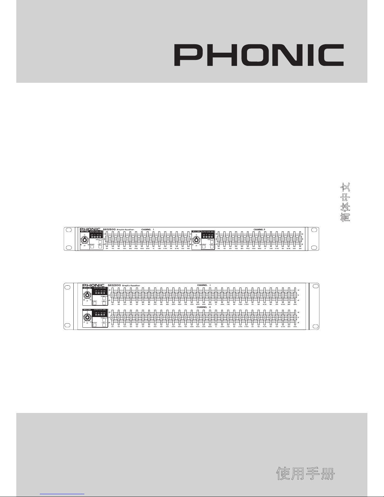
GEQ1500/GEQ3100
GRAPHIC EQUALIZER
ECUALIZADOR GRÁFICO
图示均衡器
GEQ1500
GEQ3100
English / Español / 简体中文
Page 2

GEQ1500/GEQ3100
GRAPHIC EQUALIZER
ECUALIZADOR GRÁFICO
图示均衡器
INTRODUCTION........................4
FEATURES.................................4
QUICK INSTALLATION..............4
CONTROLS AND SETTINGS....5
SPECIFICATIONS......................6
APPLICATION...........................15
DIMENSIONS...........................16
BLOCK DIAGRAMS..................17
CONTENTS
INTRODUCCION................................8
CARACTERISTICAS..........................8
INSTALACIÓN RÁPIDA......................8
CONTROLES Y CONFIGURACIONES...9
ESPECIFICACIONES......................10
APLICACION....................................15
DIMENSIONES................................16
DIAGRAMAS DE BLOQUE..............17
CONTENIDO
目录
简介...............................12
特色...............................12
快速安装........................12
控制和设置....................13
规格...............................14
应用...............................15
尺寸...............................16
方块图............................17
Phonic preserves the right to improve or alter any information within this document without prior notice
Phonic se reserva el derecho de mejorar o alterar cualquier información provista dentro de este documento sin previo aviso
PHONIC保留不预先通知便可改变或更新本文件权利
V1.0 11/07/2008
Page 3
1. Read these instructions before operating this
apparatus.
2. Keep these instructions for future reference.
3. Heed all warnings to ensure safe operation.
4. Follow all instructions provided in this document.
5. Do not use this apparatus near water or in locations
where condensation may occur.
6. Clean only with dry cloth. Do not use aerosol or liquid
cleaners. Unplug this apparatus before cleaning.
7. Do not block any of the ventilation openings. Install
in accordance with the manufacturer’s instructions.
8. Do not install near any heat sources such as radiators,
heat registers, stoves, or other apparatus (including
.
9. Do not defeat the safety purpose of the polarized or
grounding-type plug. A polarized plug has two blades
with one wider than the other. A grounding type plug
has two blades and a third grounding prong. The wide
blade or the third prong is provided for your safety. If
the provided plug does not into your outlet, consult
an electrician for replacement of the obsolete outlet.
10. Protect the power cord from being walked on or
pinched particularly at plug, convenience receptacles,
and the point where they exit from the apparatus.
11. Only use attachments/accessories by the
manufacturer.
12. Use only with a cart, stand, tripod, bracket, or
table by the manufacturer, or sold with
the apparatus. When a cart is used, use caution
when moving the cart/apparatus
combination to avoid injury from tipover.
13. Unplug this apparatus during lighting
storms or when unused for long
periods of time.
14. Refer all servicing to service personnel.
Servicing is required when the apparatus has been
damaged in any way, such as power-supply cord or
plug is damaged, liquid has been spilled or objects
have fallen into the apparatus, the apparatus has
been exposed to rain or moisture, does not operate
normally, or has been dropped.
IMPORTANT SAFETY INSTRUCTIONS
CAUTION: TO REDUCE THE RISK OF ELECTRIC SHOCK,
DO NOT REMOVE COVER (OR BACK)
NO USER SERVICEABLE PARTS INSIDE
REFER SERVICING TO QUALIFIED PERSONNEL
The lightning flash with arrowhead symbol, within an
equilateral triangle, is intended to alert the user to the
presence of uninsulated “dangerous voltage” within the
product
’
magnitude to constitute a risk of electric shock to persons.
The exclamation point within an equilateral triangle is in-
tended to alert the user to the presence of important operat-
ing and maintenance (servicing) instructions in the literature
accompanying the appliance.
WARNING: To reduce the risk of or electric shock, do
not expose this apparatus to rain or moisture.
CAUTION: Use of controls or adjustments or performance
of procedures other than those may result in
hazardous radiation exposure.
The apparatus shall not be exposed to dripping or splashing and that no objects with liquids, such as vases,
shall be placed on the apparatus. The MAINS plug is used as the disconnect device, the disconnect device shall
remain readily operable.
Warning: the user shall not place this apparatus in the area during the operation so that the mains switch
can be easily accessible.
CAUTION
RISK OF ELECTRIC SHOCK
DO NOT OPEN
Page 4

4 GEQ1500 / GEQ3100
INTRODUCTION
Congratulations on your purchase of another great product from
Phonic. The GEQ 1500 and 3100 Graphic Equalizers are both
stylish and intelligent. As far as entry-level graphic equalizers go,
you won’t nd a more reliable and easy-to-use EQ. Made with
high quality components, including super-smooth potentiometer
sliders and internal torodial transformer, this is the ideal equalizer
to take on tour, or to be installed in any live venue.
We understand that you’re eager to use this unit; however we
strongly suggest reading this user’s guide to make full use of this
equalizer’s functions. After carefully reading this manual, please
store it in a place that is easy to nd in future, in case there’s
something you missed the rst time around.
FEATURES
● GEQ1500 – Two 15-band, 2/3-octave Constant Q frequency
bands
● GEQ3100 – Two 31-band, 1/3-octave Constant Q frequency
bands
● Switchable boost/cut ranges of ±6 or ±12 dB
● 12 dB per octave 50Hz low-cut lter
● Front-panel bypass switch
● ±15 dB input gain range
● 4-segment LED meter for monitoring output levels
● XLR and TRS Inputs and Outputs
● Internal Toroidal Transformer
● Frequency Response of <10Hz to >50kHz
● Dynamic range greater than 108dB
Quick Installation
1. Make sure your GEQ is off. Preferably remove the AC power
cable.
2.
Connect all of your required output devices to the GEQ’s inputs.
If it’s a stereo device, use both of the GEQ’s channels. If you’re
using a mono signal, simply use a single channel. The other
channel will then be free for a second mono signal.
3.
Connect all of your required input devices to the GEQ’s output
connectors. This may include ampliers or mixers (if you’re
using an insert point).
4.
Turn your devices on in this order: instruments, mixer, signal
processors, amps/speakers.
Page 5
5GEQ1500 / GEQ3100
CONTROLS AND SETTINGS
Front Panel
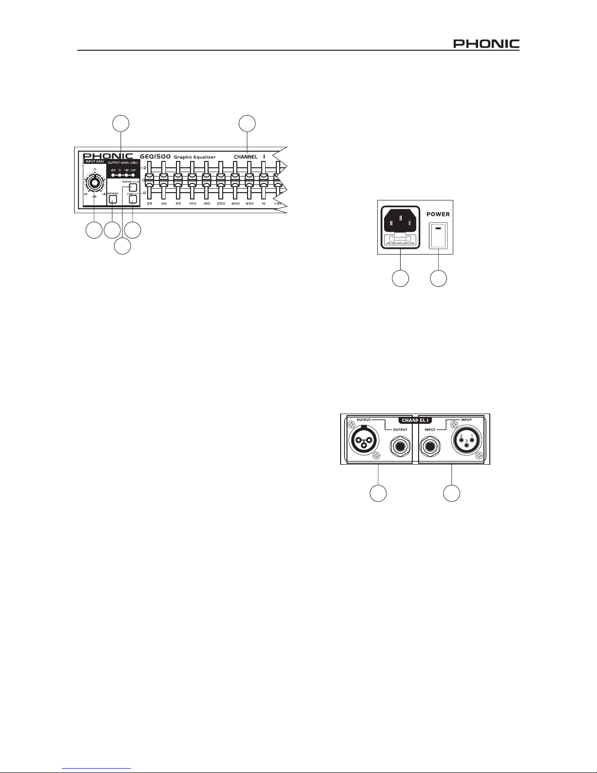
1. Input Gain Control
This control adjusts the level of the input signal that is sent to the
equalizer. It provides between -15dB and +15dB of gain.
2. EQ Bypass Button
Pushing this button in removes the equalizer from your signal
path. The input gain and low cut lters are not affected, however.
3. Boost/Cut Range Button
This button selects which of the two boost/cut ranges the equalizer will use, either ±6dB or ±12dB. When pushed in, the ±6dB
option is used, and when released the ±12dB option is used.
4. Output Level Meter
These four LEDs indicate the output level of the equalizer. The
red clip LED marks the point 3dB before clipping occurs. If this
occurs, it’s advised to adjust the input gain control to a point that
will cause this LED to ash only occasionally, or reduce the level of
any frequency sliders that may have excessively high signals.
5. Low Cut Button
When the low cut button is pushed in it will affectively reduce all
frequencies below 50 Hz in your signal at 12dB/octave.
6. Frequency Band Slider Controls
Each of these sliders will boost or cut the corresponding frequency
by ±6dB or ±12dB (depending on the settings determined by
the boost/cut button). All sliders are center detented, and this
position indicates that the corresponding frequency will have a
at response. The frequency band centers of the GEQ3100 are
marked at 1/3 octave intervals at ISO standard intervals, whereas
the frequency band centers of the GEQ1500 are marked at 2/3
octave intervals on ISO standard intervals.
Rear Panel
7. Power Cord Receptacle
Connect the provided AC power cable to the GEQ equalizer here.
Please be aware of local voltage levels before connecting the
unit to the mains power supply.
8. Power Switch
Use this switch to turn the power on and off. Keep this switch in
the off position when making audio connections.
9. Output Connectors
These male XLR-type and 1/4” TRS phone jack connectors are
provided to send the processed signal to external devices.
10. Input Connectors
These female XLR-type and 1/4” TRS phone jack connectors are
provided to receive signals from external devices to be processed
by the GEQ equalizer. The maximum input level that the equalizer
can accept is +22dBu (ref: 0.775Vrms).
9 10
7 8
3
5
21
4
6
Page 6
6 GEQ1500 / GEQ3100
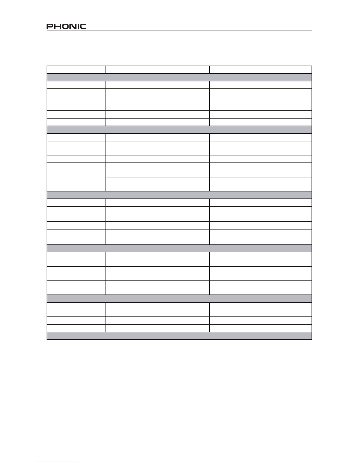
SPECIFICATIONS
GEQ1500 GEQ3100
INPUT
Connectors: 1/4” TRS, female XLR (pin 2 hot) 1/4” TRS, female XLR (pin 2 hot)
Type: Electronically balanced/unbalanced,
RF ltered
Electronically balanced/unbalanced,
RF ltered
Impedance: Balanced 40k ohm, unbalanced 20k ohm Balanced 40k ohm, unbalanced 20k ohm
Max Input Level: >+21dBu balanced or unbalanced >+21dBu balanced or unbalanced
CMRR: >40dB, typically >55dB at 1kHz >40dB, typically >55dB at 1kHz
OUTPUTS
Connectors: 1/4” TRS, male XLR (pin 2 hot) 1/4” TRS, male XLR (pin 2 hot)
Type: Impedance-balanaced/unbalanced,
RF ltered
Impedance-balanced/unbalanced,
RF ltered
Impedance: Balanced 100 ohm, unbalanced 50 ohm Balanced 100 ohm, unbalanced 50 ohm
Max Output Level: >+21dBu balanced/unbalanced into 2k ohm or
greater
>+21dBu balanced/unbalanced into 2k ohm or
greater
>+18dBm balanced/unbalanced
(into 600 ohm)
>+18dBm balanced/unbalanced
(into 600 ohm)
SYSTEM PERFORMANCE
Bandwidth: 20Hz to 20kHz, +0.5/-1dB 20Hz to 20kHz, +0.5/-1dB
Frequency Response: <10Hz to >50kHz, +0.5/-3dB <10Hz to 45kHz, +0.5/-3dB
Dynamic Range: 108dB 108dB
Signal-to-Noise: 90dB 90dB
THD+Noise: <0.004% <0.004%
Interchannel Crosstalk: <-80dB, 20Hz to 20kHz <-80dB, 20Hz to 20kHz
FUNCTION SWITCHES
EQ Bypass: Bypasses the graphic equalizer section
in the signal path
Bypasses the graphic equalizer section
in the signal path
Low Cut: Activates the 50Hz 12dB/octave
high-pass lter
Activates the 50Hz 12dB/octave
high-pass lter
Range: Selects either +/- 6dB or +/- 12dB
slider boost/cut range
Selects either +/- 6dB or +/- 12dB
slider boost/cut range
POWER SUPPLY
Operating Voltage: 100VAC 50/60Hz, 120VAC 60Hz,
230VAC 50/60Hz
100VAC 50/60Hz, 120VAC 60Hz,
230VAC 50/60Hz
Power consumption: 12W 15W
Main Connection: IEC receptacle IEC receptacle
Note: Specications subject to change without notice.
Page 7

Page 8

8 GEQ1500 / GEQ3100
INTRODUCCIÓN
Fe licitac io nes por su compra de otro gr an prod uc to de
Phonic. Ambos Ecualizadores Grácos GEQ1500 y 3100 son
elegantes e inteligentes. Hasta donde llegan los ecualizadores
grácos de nivel de entrada, usted no encontrará un EQ más
confiable y fácil de usar. Hecho con componentes de alta
calidad, incluyendo deslizadores de potenciómetro super-liso y
transformador torodial interno, éste es el ecualizador ideal para
llevar en gira o ser instalado en cualquier lugar en vivo.
En te nd em os que está ancioso de us ar esta unidad, sin
embargo, le sugerimos encarecidamente que lea esta guía
de usuario para hacer uso completo de las funciones de este
ecualizador. Después de leer este manual, por favor guardelo
en un lugar de fácil acceso en el futuro, en caso que se le haya
escapado algo en la peimera leída.
CARACTERÍSTICAS
GEQ1500 – Dos 15-bandas, 2/3-octava bandas d e
frecuencia de Constante Q
GEQ3100 – Dos 31-bandas, 1/3-octava bandas d e
frecuencia de Constante Q
Aumento/corte intercambiable de rangos de ±6 o ±12 dB
Filtro de corte bajo 12dB por octava 50Hz
Interruptor de bypass en panel frontal
Rango de ganancia de entrada de ±15 dB
Me didor LED de 4 se gmentos para mo nitorear los
niveles de salida
Entradas y Salidas de XLR y TRS
Transformador Toroidal Interno
Respuesta en frecuencia de <10Hz a >50kHz
Rango dinámico mayor que 108dB
INSTALACIÓN RÁPIDA
1. Asegúrese que su GEQ esté apagado. Preferentemente
remueva el cable de energía AC.
2.
Conecte todos los dispositivos de salida necesarios a las
entradas de GEQ. Si es un dispositivo de estéreo, utilice
ambos canales de GEQ. Si está utilizando una señal
mono, utilice simplemente un canal simple. El otro canal
estará libre para segunda señal mono.
3.
Conecte todos los dispositivos de entrada necesarios
a los conectores de salida de GEQ. Ésto podría incluir
amplicadores o mezcladoras (si usted está utilizando un
punto de inserción).
4.
Encienda sus dispositivos en este orden: instrumentos,
mezcladora, procesadores de señal, amplificadores/
altavoces.
Page 9

9GEQ1500 / GEQ3100
CONTROLES Y CONFIGURACIONES
Panel Frontal
Panel Dorsal
7. Receptor de Cable de Energía
Conecte aquí el cable de energía AC a ecualizador GEQ. Por
favor conozca los niveles de voltaje local antes de conectar la
unidad a suminitro de energía principal.
8. Interruptor de Energía
Utilice este interruptor para encender y apagar la energía.
Mantenga este interruptor en la posición de apagado cuando
realiza las conexiones de audio.
9. Conectores de Salida
Estos conectores de jack audífono de tipo XLR macho y 1/4”
TRS son proporcionados para enviar la señal procesada a
dispositivos externos.
10. Conectores de Entrada
Estos conectores de jack audífono de tipo XLR hembra y 1/4
TRS son proporcionados para recibir las señales desde los
dispositivos externos para ser procesadas por el ecualizador
GEQ. El nivel de entrada máximo que el ecualizador puede
aceptar es +22dBu (ref:0.775Vrms).
3
5
21
4
6
9 10
7 8
1. Control de Ganancia de Entrada
Este control ajusta el nivel de la señal de entrada que es
enviada al ecualizador. Provee ganancia entre -15dB y +15dB.
2. Botón de Bypass de EQ
Al pulsar este botón remueve el ecualizador de su camino de
la señal. Sin embargo, la ganancia de la entrada y los ltros de
corte bajo no están afectados.
3. Botón de Rango de Aumento/Corte
Este botón selecciona cuál de los dos rangos de aumento/corte
se utilizará el ecualizador, ±6dB o ±12dB. Cuando está pulsado,
se utiliza la opción ±6dB y, cuando no está pulsado la opción ±
12dB es la que se utiliza.
4. Medidor de Nivel de Salida
Estos cuatro LEDs indican el nivel de la salida de ecualizador.
El LED de recorte rojo marca el punto 3dB antes de que el
recorte ocurra. Si ésto ocurre, se aconseja ajustar el control
de ganancia de entrada a un punto donde este LED se ilumine
solo ocasionalmente o, reduce el nivel de cualquier deslizador
de frecuencia que podría tener señales excesivamente altas.
5. Botón de Corte Bajo
Cuand o el botó n de cort e baj o está pu lsado , redu cirá
efectivamente todas las frecuencias por debajo de 50 Hz en su
señal en 12dB/octava.
6. Controles de Deslizador de Banda de Frecuencia
Ca da uno de es tos deslizado re s aumentará o c or tará la
frecuencia correspondiente por ±6dB o ±12dB (dependiendo
de las configuraciones determinadas por el botón aumento/
corte). Todos los deslizadores son centros de detención y,
esta posición indica que la frecuencia correpondiente tendrá
una respuesta plana. Los centros de la banda de frecuencia
de GEQ3100 son marcados en intervalos de 1/3 octava de
intervalos estándares de ISO, en tanto los centros de la banda
de frecuencia de GEQ1500 son marcados en intervalos de 2/3
octava de intervalos estándares de ISO.
Page 10

10 GEQ1500 / GEQ3100
ESPECIFICACIONES
GEQ1500 GEQ3100
ENTRADA
Conectores: 1/4” TRS, XLR hembra (pin 2 hot) 1/4” TRS, XLR hembra (pin 2 hot)
Tipo:
Electrónicamente balanceado/desbalanceado,
RF ltrado
Electrónicamente balanceado/desbalanceado,
RF ltrado
Impedancia:
Balanceada 40k ohm,
desbalanceada 20k ohm
Balanceada 40k ohm,
desbalanceada 20k ohm
Nivel de Entrada Máximo: >+21dBu balanceado o desbalanceado >+21dBu balanceado o desbalanceado
CMRR: >40dB, normalmente >55dB en 1kHz >40dB, normalmente >55dB en 1kHz
SALIDAS
Conectadores: 1/4” TRS, XLR macho (pin 2 hot) 1/4” TRS, XLR macho (pin 2 hot)
Tipo:
Impedancia-balanceada /
desbalanceada, RF ltrado
Impedancia-balanceada /
desbalanceada, RF ltrado
Impedancia:
Balanceada 100 ohm,
desbalanceada 50 ohm
Balanceada 100 ohm,
desbalanceada 50 ohm
Nivel de Salida Máximo:
>+21dBu balanceado/
desbalanceado en 2k ohm o mayor
>+21dBu balanceado/
desbalanceado en 2k ohm o mayor
>+18dBm balanceado/
desbalanceado (en 600 ohm)
>+18dBm balanceado/
desbalanceado (en 600 ohm)
FUNCIONAMIENTO DEL SISTEMA
Ancho de banda: 20Hz a 20kHz, +0.5/-1dB 20Hz a 20kHz, +0.5/-1dB
Respuesta en Frecuencia: <10Hz a >50kHz, +0.5/-3dB <10Hz a 45kHz, +0.5/-3dB
Rango Dinámico: 108dB 108dB
Señal a Ruido: 90dB 90dB
THD+Ruido: <0.004% <0.004%
Crosstalk Intercanal: <-80dB, 20Hz a 20kHz <-80dB, 20Hz a 20kHz
INTERRUPTORES DE FUNCIÓN
EQ Bypass:
Bypass la sección de ecualizador gráco en el
camino de señal
Bypass la sección de ecualizador gráco en el
camino de señal
Corte Bajo:
Activa ltro de paso alto de
50Hz 12dB/octava
Activa ltro de paso alto de
50Hz 12dB/octava
Rango:
Selecciona rango de deslizador de aumento/
corte de +/- 6dB o +/-12dB
Selecciona rango de deslizador de aumento/
corte de +/- 6dB o +/-12dB
SUMINISTRO DE ENERGÍA
Voltaje de Operación:
100VAC 50/60Hz, 120VAC 60Hz,
230VAC 50/60Hz
100VAC 50/60Hz, 120VAC 60Hz,
230VAC 50/60Hz
Consumo de energía: 12W 15W
Conexión Principal: Receptor IEC Receptor IEC
Nota: Las especicaciones están sujetas a cambio sin previo aviso.
Page 11

重要安全说明
1. 请在使用本机前,仔细阅读以下说明。
2. 请保留本使用手册,以便日后参考。
3. 为保障操作安全,请注意所有安全警告。
4. 请遵守本使用手册内所有的操作说明。
5. 请不要在靠近水的地方,或任何空气潮湿的地点操作本机。
6. 本机只能用干燥布料擦拭,请勿使用喷雾式或液体清洁剂。清洁本机前请先将电源插头拔掉。
7. 请勿遮盖任何散热口。确实依照本使用手册来安装本机。
8. 请勿将本机安装在任何热源附近。例如:暖气、电暖气、炉灶或其它发热的装置(包括功率
扩大机)。
9. 请注意极性或接地式电源插头的安全目的。极性电源插头有宽窄两个宽扁金属插脚。接地式
电源插头有两支宽扁金属插脚和第三支接地插脚。较宽的金属插脚(极性电源插头)或第三支
接地插脚(接地式电源插头)是为安全要求而制定的。如果随机所附的插头与您的插座不符,
请在更换不符的插座前,先咨询电工人员。
10. 请不要踩踏或挤压电源线,尤其是插头、便利插座、电源线与机身相接处。
11. 本机只可以使用生产商指定的零件/配件。
12. 本机只可以使用与本机搭售或由生产商指定的机柜、支架、三脚架、拖架
或桌子。在使用机柜时,请小心移动已安装设备的机柜,以避免机柜翻倒
造成身体伤害。
13. 在雷雨天或长期不使用的情况下,请拔掉电源插头。
14. 所有检查与维修都必须交给合格的维修人员。本机的任何损伤都须要检修,例如: 电源线或插
头受损,曾有液体溅入或物体掉入机身内,曾暴露于雨天或潮湿的地方,不正常的运作,或曾
掉落等。
这个三角形闪电标志是用来警告用户,装置内的非绝缘危险电压足以造成使人触
电的
危险性。
这个三角形惊叹号标志是用来警告用户,随机使用手册中有重要操作与保养维修
说明。
警告: 为减少火灾或触电的危险性,请勿将本机暴露于雨天或潮湿的地方。
注意: 任何未经本使用手册许可的操控,调整或设定步骤都可能产生危险的电磁幅射。
CAUTION
RISK OF ELECTRIC SHOCK
DO NOT OPEN
PHONIC CORPORATION
Page 12

12 GEQ1500 / GEQ3100
简介
感谢您购买Phonic品牌的优质产品。GE Q1 50 0和GEQ3100是
时尚智慧的图示均衡器。在图示均衡器领域里 您再也 找不到 比
GEQ1500和GEQ3100更值得信赖,更容易使用的EQ了,它们由
高品质的材料构成,含超平滑分压计滑杆,内设环形变压器,是
旅行乐团和现场音乐会的理想选择。
您一定早已迫不及待地想一试为快,尽情地享用。这台设备可能
是您的首选,但是,我们强烈恳请您先仔细阅读此手册,全面了
解这台均衡器的功能。读完后请妥善保管,以便日后参阅。
特色
• GEQ1500---两组15段,2/3oct固定Q频率波段
•
GEQ3100---两组31段,1/3oct固定Q频率波段
•
可变换式±6或±12dB信号增强或削减控制
• 12dB/oct
50Hz高通滤波
•
前方面板旁通开关
• ±1
5dB输入增益
• 4
段LED电平表监控输出信号
•
内建环形变压器
•
频率响应范围:10Hz~50KHz
•
大于108dB的动态范围
快速安装
1.确保关闭GEQ的电源,移除AC电源线。
2.将所需的输出装置连接至GEQ的输入端口。若为立体设备,使
用GEQ的两个声道;若为单声道信号,只需简单的使用一个信
号声道。另一声道闲置以备接入另一单声道信号。
3.将所需的输入装置连接至GEQ的输出端口,包括功率放大器或
调音台(若使用的为插入端口)。
4.按以下 顺序开启设备:乐器,调 音台,信号处理器,功放/音
箱。
Page 13

13GEQ1500 / GEQ3100
9 10
7 8
3
5
21
4
6
控制和设置
前方面板
1.输入增益控制 Input Gain Control
此 旋 钮可调节 输 往 均 衡 器 的 输 入信号的 大 小 。 增 益 范 围 为
-15dB~+15dB。
2.EQ旁通控制钮 EQ Bypass Button
按下此钮可将均衡器从您的信号通道移除,输入增益和低切滤波
器也将无效。
3.增强/削减范围控制 Boost/Cut Range Button
此按钮可选择均衡器使用的增强/衰减范围是± 6dB还是± 12 dB。
按下此钮,使用的为±6dB,释放使用的为±12dB。
4.输出电平表 Output Level Meter
这四个LED可指示均衡器的输出电平。红色的Clip LED可在信号
削减前指示点3dB.如果发生此现象,建议调节输入增益控制至一
定的位置,使LED灯只是偶然的闪亮,或减小频率滑杆的电平数
值。
5.低切控制 Low Cut Button
按下此按钮将对低于50Hz的信号进行12dB/oct的切除。
6.频率段滑杆控制 Frequency Band Slider Controls
每一个滑杆可对相应的频率进行±6dB或±12dB增强或衰减(取决
于增强/削减控制钮)。所有的滑杆都位于中心位置,也就是说相
应的频率可进行平稳的响应。GEQ3100的频率段是按照ISO标准
以1/3oct的间隔来标识的,GEQ1500为2/3oct。
后方面板
7.电源线插座 Power Cord Receptacle
将提供的A C电源线插入GE Q均衡器电源线插孔。将设备连接至
主电源供应器时请核对当地电压值。
8.电源开关 Power Switch
此开关可控制GEQ电源的开和关。连接其它设备时,请确保电源
开关处于OFF关闭的位置。
9.输出连接器 Output Connectors
这个公XL R型和1/4” TR S耳机插孔连接器,可将处理的信号输送
至外部设备。
10.输入连接器 Input Connectors
这个母XL R型和1/4” TR S耳机插孔连接器,可将外部设备的信号
输送至 GE Q均衡器。均 衡器可接 收的最大输入电平为+22d Bu
(参照:0.775Vrms)。
Page 14

14 GEQ1500 / GEQ3100
规格
GEQ1500 GEQ3100
输入
连接器
1/4”TRS,母XLR( 端 2 热端 ) 1/4”TRS,母XLR( 端 2 热端 )
类型 电子平衡/非平衡,RF滤波 电子平衡/非平衡,RF滤波
阻抗 平衡 40k ohm,非平衡 20k ohm 平衡 40k ohm,非平衡 20k ohm
最大输入电平
>+21dBu平衡或非平衡 >+21dBu平衡或非平衡
CMRR >40dB,1kHz时>55dB >40dB,1kHz时>55dB
输出
连接器
1/4”TRS,公XLR( 端 2 热端 ) 1/4”TRS,公XLR( 端 2 热端 )
类型 阻抗-平衡/非平衡,RF滤波 阻抗-平衡/非平衡,RF滤波
阻抗 平衡 100 ohm,非平衡 50 ohm 平衡 100 ohm,非平衡 50 ohm
最大输出电平
>+21dBu平衡或非平衡至2k ohm 或更大 >+21dBu平衡或非平衡至2k ohm 或更大
>+18dBm平衡或非平衡(至600 ohm) >+18dBm平衡或非平衡(至600 ohm)
系统性能
频宽
20Hz~20kHz,+0.5/-1dB 20Hz~20kHz,+0.5/-1dB
频率响应
10Hz~50kHz,+0.5/-3dB 10Hz~45kHz,+0.5/-3dB
动态范围
108dB 108dB
信噪比
90dB 90dB
THD + 噪音 <0.004% <0.004%
通道间串音
<-80dB,20Hz~20kHz <-80dB,20Hz~20kHz
功能开关
EQ旁通
旁通信号通道的图示均衡区 旁通信号通道的图示均衡区
低切 激活50Hz 12dB/oct高通滤波 激活50Hz 12dB/oct高通滤波
范围 切换±6dB或±12dB滑杆增强或衰减信号 切换±6dB或±12dB滑杆增强或衰减信号
电源供应
操作电压
100VAC 50/60Hz,120VAC 60Hz,230VAC 50/60Hz 100VAC 50/60Hz,120VAC 60Hz,230VAC 50/60Hz
功率消耗
12W 15W
主连接
IEC插座 IEC插座
注意:规格若有变更,恕不通知!
Page 15

15GEQ1500 / GEQ3100
APPLICATION APLICACIÓN 应用
MIXER
MIXER
INSERT POINT
SPEAKER
AMP
ALTAVOZ
MEZCLADORA
MEZCLADORA
PUNTO DE INSERCIÓN
调音台
插入点
功率放大器
音 箱
调音台
Page 16

16 GEQ1500 / GEQ3100
measurements are shown in mm/inches
482 /19
44/ 1.7
183 /7.
2
GEQ1500
482/19
88/3.
6
183/7.
2
GEQ3100
DIMENSIONS DIMENSIONES 尺寸
Todas las medidas están mostradas en mm/pulgadas.
尺寸是以毫米
mm/英寸inch
表示。
Page 17

17GEQ1500 / GEQ3100
BLOCK DIAGRAMS DIAGRAMAS DE BLOQUE 方块图
GEQ1500
Page 18

18 GEQ1500 / GEQ3100
GEQ3100
Page 19

support@phonic.com http://www.phonic.com
CÓMO COMPRAR EQUIPO ADICIONAL
Y ACCESORIOS DE PHONIC
Para comprar equipos y accesorios opcionales de
Phonic, póngase en contacto con cualquiera de los
distribuidores autorizados de Phonic. Para una lista
de los distribuidores de Phonic visite nuestra página
web en www.phonic.com y entre a la sección Get
Gear. También, puede ponerse en contacto directa
mente con Phonic y le ayudaremos a encontrar un
distribuidor cerca de usted.
SERVICIO Y REPARACIÓN
Para refacciones de reemplazo y reparaciones, por
favor póngase en contacto con nuestro distribuidor
de Phonic en su país. Phonic no distribuye manuales
de servicio directamente a los consumidores y, avisa
a los usuarios que no intenten hacer cualquier
reparación por si mismo, haciendo ésto invalidará
todas las garantías del equipo. Puede encontrar un
distribuidor cerca de usted en
http://www.phonic.com/where/.
INFORMACIÓN DE LA GARANTIA
Phonic respalda cada producto que hacemos con
una garantía sin enredo. La cobertura de garantía
podría ser ampliada dependiendo de su región.
Phonic Corporation garantiza este producto por un
mínimo de un año desde la fecha original de su
compra, contra defectos en materiales y mano de
obra bajo el uso que se instruya en el manual del
usuario. Phonic, a su propia opinión, reparará o
cambiará la unidad defectuosa que se encuentra
dentro de esta garantía. Por favor, guarde los recibos
de venta con la fecha de compra como evidencia de
la fecha de compra. Va a necesitar este comprobante
para cualquier servicio de garantía. No se aceptarán
reparaciones o devoluciones sin un número RMA
apropiado (return merchandise autorization). En
orden de tener esta garantía válida, el producto
deberá de haber sido manejado y utilizado como se
describe en las instrucciones que acompañan esta
garantía. Cualquier atentado hacia el producto o
cualquier intento de repararlo por usted mismo,
cancelará completamente esta garantía. Esta
garantía no cubre daños ocasionados por accidentes, mal uso, abuso o negligencia. Esta garantía es
válida solamente si el producto fue comprado nuevo
de un representante/distribuidor autorizado de
Phonic. Para la información completa acerca de la
política de garantía, por favor visite
http://www.phonic.com/warranty/.
SERVICIO AL CLIENTE Y SOPORTE
TÉCNICO
Le invitamos a que visite nuestro sistema de ayuda
en línea en www.phonic.com/support/. Ahí podrá
encontrar respuestas a las preguntas más frecuen
tes, consejos técnicos, descarga de drivers, instruc
ciones de devolución de equipos y más información
de mucho interés. Nosotros haremos todo el
esfuerzo para contestar sus preguntas lo antes
posible.
TO PURCHASE ADDITIONAL
PHONIC GEAR AND ACCESSORIES
To purchase Phonic gear and optional
accessories, contact any authorized
Phonic distributor. For a list of Phonic
distributors please visit our website at
www.phonic.com and click on Get Gear.
You may also contact Phonic directly and
we will assist you in locating a distributor
near you.
SERVICE AND REPAIR
For replacement parts, service and repairs
please contact the Phonic distributor in
your country. Phonic does not release
service manuals to consumers, and advice
users to not attempt any self repairs, as
doing so voids all warranties. You can
locate a dealer near you at
http://www.phonic.com/where/.
WARRANTY INFORMATION
Phonic stands behind every product we
make with a no-hassles warranty.
Warranty coverage may be extended,
depending on your region. Phonic Corpo
ration warrants this product for a minimum
of one year from the original date of
purchase against defects in material and
workmanship under use as instructed by
the user’s manual. Phonic, at its option,
shall repair or replace the defective unit
covered by this warranty. Please retain the
dated sales receipt as evidence of the date
of purchase. You will need it for any
warranty service. No returns or repairs will
be accepted without a proper RMA number
(return merchandise authorization). In
order to keep this warranty in effect, the
product must have been handled and used
as prescribed in the instructions accompa
nying this warranty. Any tempering of the
product or attempts of self repair voids all
warranty. This warranty does not cover
any damage due to accident, misuse,
abuse, or negligence. This warranty is
valid only if the product was purchased
new from an authorized Phonic
dealer/distributor. For complete warranty
policy information, please visit
http://www.phonic.com/warranty/.
CUSTOMER SERVICE AND
TECHNICAL SUPPORT
We encourage you to visit our online help
at http://www.phonic.com/support/. There
you can find answers to frequently asked
questions, tech tips, driver downloads,
returns instruction and other helpful
information. We make every effort to
answer your questions within one business
day.
购买Phonic产 品 及其周边
器材
使用者如需购买Phonic产品及其周边
器材,请与Phonic授权的经销商取得
联 系 。 访 问 我 们 的 网 站
www.phonic.com,点击 Get Gear 即
可查询 Phonic地 区经销 商的联 系方
式。您也可直接联系Phonic公司,我
们将协助您快速定位离您最近的经销
商。
服务与维修
订购替换零件或维修事宜,请与您所
在地区的Phonic经销商联系。Phonic
不对使用者发行维修手册,且建议使
用者切勿擅自维修机器,否则将无法
获 得 任 何 保 固 服 务 。 您 可 登 录
http://www.phonic.com/where/定位离
您最近的经销商。
产品保固资讯
Phonic承诺对每项产品提供最完善的
保固服务。我们将根据客户群体所在
的地区来拓展我们的服务所涵盖的范
围。自原始购买日起,Phonic即对在
严格遵照使用说明书的操作规范下,
因产品材质和做工所产生的问题提供
至少 1年的 保固服务。 Phonic可在此
保固范围内任意地选择维修或更换缺
陷产品。请务必妥善保管购买产品的
凭证, 以 此获得 保固服 务 。未获 得
RMA号的将不受理退货,以及保固服
务。保固服务只限于正常使用情况下
产生的问题。使用者需严格遵照使用
说明书正确使用,任何肆意损坏或擅
自维修机器,意外事故,错误使用,
人为疏 忽 ,都将 不在保 固 受理范 围
内。此外,担保维修只限于在授权经
销商处的有效购买。欲知全部的保固
政 策 资 讯 , 请 参 考
http://www.phonic.com/warranty/。
客户服务和技术支持
欢 迎 您 访 问 我 们 的 网 站
http://www.phonic.com/support/。从
该网站上,您可获得各种常见问题的
答案, 技 术指导 ,并可 下 载产品 驱
动,获得有关退货指导以及其它帮助
资讯。我们竭尽全力在一个工作日内
回复您的询问。
Page 20

 Loading...