

Phonic EAR Logibit 1200 User Manual

LOGIBIT 1200
MANUAL

LogiBit 1200 manual
Table of Contents
TABLE OF CONTENTS
1. FEATURES ON THE CONTROL PANEL............................................................... 1
2. MENU STRUCTURE................................................................................................. 2
2.1 Function keys............................................................................................................................ 2
2.2 Menu points.............................................................................................................................. 2
2.3 Illustration of menu structure.............................................................................................. 5
3. FEATURES ON THE BACK PANEL......................................................................... 8
3.1 General....................................................................................................................................... 8
3.2 Options...................................................................................................................................... 10
3.3 Installation of front to 19” rack............................................................................................ 11
3.4 Fuses and 115/230 volt AC exchanger................................................................................ 11
3.5 Control port............................................................................................................................. 12
3.6 Serial port.................................................................................................................................. 13
4. SAFETY INFORMATION......................................................................................... 14
5. APPROVAL................................................................................................................ 14
6. BLOCK DIAGRAM.................................................................................................... 15
7. SPECIFICATIONS..................................................................................................... 16
7.1 Technical data............................................................................................................................ 16
7.2 Special functions...................................................................................................................... 17
7.3 Options...................................................................................................................................... 17
LogiBit 1200 manual
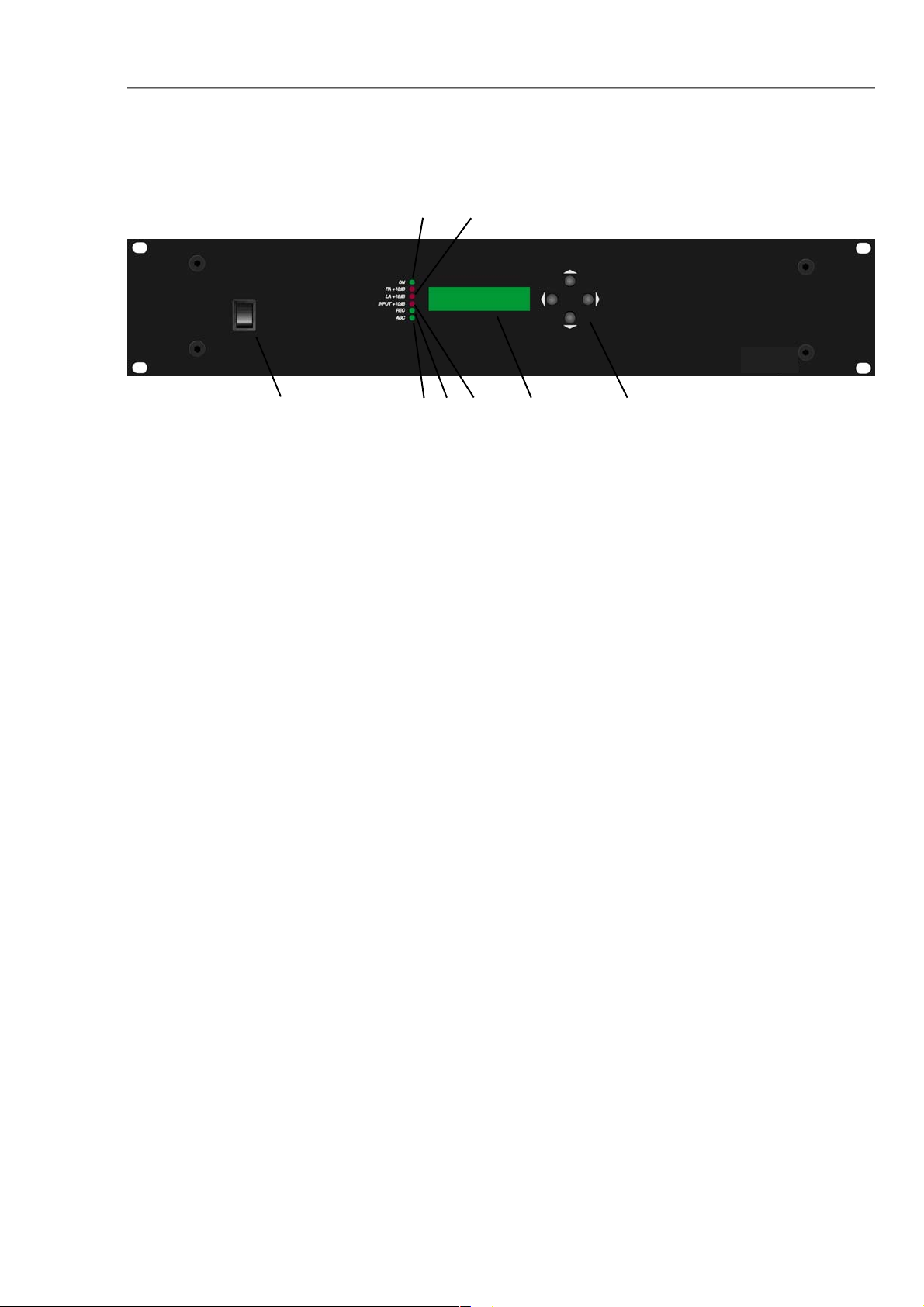
1. FEATURES ON THE CONTROL PANEL
➁➂
Features on the Control Panel
➀
➀ On/Off Switch: This switch switches the amplifi er on and off.
➁ On indicator: This green LED lights when the amplifi er is on.
➂ LA +18 dB indicator: This red LED lights, when the signal level on the teleloop
amplifi er has reached maximum. With correct amplifi er
adjustment this LED should never light.
➃ INPUT +10 dB indicator: This red LED lights, when any one of the two to fi ve +10 dB
indicators on the back of the amplifi er lights. With correct
amplifi er adjustment this LED should only blink when there are
loud passages otherwise the level of the signal fed to the input
of the amplifi er is too high.
➄ REC indicator: This green LED lights, when REC function is chosen. The green
LED is turned off, when the play function is chosen.
➅ AGC indicator: This green LED lights, when the AGC-circuit is active.
➃➅➆➄➇
➆ Display
➇ 4 function keys: The LogiBit 1200 amplifi er’s 4 function keys are described in
section 2.1 Function keys.
1

LogiBit 1200 manual
2. MENU STRUCTURE
2.1 FUNCTION KEYS
Menu Structure
➁
➀
➂
➃
➀ LEFT/UNDO: With this key you can move to the left in the menu structure.
The key is also used to undo changes in a parameter, which has
not already been saved.
➁ UP/INCREASE: With this key you move upward in the menu structure. It can
also be used to change/increase a parameter.
➂ RIGHT/SAVE: With this key you move to the right in the menu structure. The
key is also used to save changes in a parameter.
➃ DOWN/DECREASE: With this key you move downward in the menu structure. The
key is also used to change/decrease a parameter.
2.2 MENU POINTS
SERVICE MODE: The individual parameters in the amplifi er can only be changed
when the LogiBit amplifi er is in SERVICE MODE. To do this you
must switch off the amplifi er at the on/off switch, then while
holding function key ➁ up/increase and ➃ down/decrease in at
the same time, turn on the amplifi er. Display will show
“SERVICE” for a short period. If the LogiBit amplifi er is
not put in SERVICE MODE the only parameters that can be
changed are RECORD and CONTRAST.
WARNING! The above may only be carried out by authorized Phonicear
personnel. It is strongly advised that no unauthorized
person is allowed to put the amplifi er in SERVICE MODE.
2

LogiBit 1200 manual
RECORD: Select “ON” when recording thereby switching off TAPE INPUT.
This avoids feedback in situations where a tape recorder is
connected to both TAPE INPUT and TAPE OUTPUT. In the
“OFF” position both TAPE INPUT and TAPE OUTPUT are
active. REC ON/OFF function can also be changed without the
amplifi er being in SERVICE MODE.
CONTRAST: Used for adjusting the contrast in the display. Contrast can also
be adjusted, without the amplifi er being in SERVICE MODE.
CODE: In connection with an upgrading of a LogiBit 1200 to a LogiBit
1260 it is necessary to type in a code (see also the next point
ID). A fter the code has been typed in, the amplifi er should be
switched off for a short period to allow the upgrading to take
effect.
ID: Before you can receive the code used in upgrading a LogiBit
1200 to a LogiBit 1260 it is necessary to give the ID-number of
the amplifi er to your Logia dealer.
Menu Structure
AUTOCAL: In connection with a new installation, changes of the area size or
changes in the dimensions of the teleloop cable, AUTOCAL
shall be “ON” the fi rst time the amplifi er is turned on. In this
position the amplifi er calibrates with the teleloop cable. When
the calibration is fi nished AUTOCAL should be in the “OFF”
position. Thereby you avoid hearing on the teleloop the calibra ting signals the amplifi er uses when it is turned on. A fter the
amplifi er has completed its calibrating procedure for the fi rst
time, the current in the teleloop cable will automatically
be set to 1 ampere. LA VOL will be automatically set to 0 dB.
LA VOL: Used to adjusting the current in the teleloop cable and thereby
the strength of the magnetic fi eld. After the amplifi er has
completed its calibrating procedure for the fi rst time, the
current in the teleloop cable will automatically be set to
1 ampere. LA VOL will be automatically set to 0 dB.
BASS: Select BASS to adjust the bass on the teleloop signal.
AGC MODE: Menu point REMOTE allows, that the AGC-circuit can be
switched on and off via the 25 pin Sub-D port marked
CONTROL on the back panel of the amplifi er. Select “OFF” to
switch off the AGC-circuit. Under normal operating conditions,
select “ON”, to activate the AGC-circuit.
AGC GAIN: Used to adjust the number of required dBs that the AGC-circuit
should use to strengthen a weak signal. The AGC-circuit is able
to reduce a powerful signal with up to 20 dBs.
TREBLE: Select TREBLE to adjust the treble on the teleloop signal.
3

LogiBit 1200 manual
MIC.1- 5: Select this menu point to change the parameters for respectively
microphone and line-in 1-5. Microphone and line-in 3-5 are not
standard, but can be built in as an option.
VOLUME: Used for adjusting the signal level immediately before mixing
point. A s a starting point choose 0 dB. If the output signal is
distorted, this parameter should be reduced.
REMOTE: REMOTE set to “ON” allows mute of line-in via the 25 pin
Sub-D port marked CONTROL on the back panel of the
amplifi er.
MIX.OUT: This menu point determines, whether a signal connected to an
input can be heard on the teleloop (LA) or not (NONE).
TA P E : Select TAPE to change the parameters for TAPE INPUT.
VOLUME: Used for adjusting the signal level immediately before mixing
point. As a starting point choose 0 dB. If the output signal is
distorted, this parameter should be reduced.
Menu Structure
MIX.OUT: This menu point determines, whether a signal connected to an
input can be heard on the teleloop (LA) or not (NONE).
REC.1 & 2: Select this menu point to change the parameters for the wire
less receiver modules. The wireless TOA receiver modules are
not standard, but can be built into the amplifi er as an option.
VOLUME: Used for adjusting the signal level immediately before mixing
point. As a starting point choose 0 dB. If the output signal is
distorted, this parameter should be reduced.
STARTUP: Select “ON” and the wireless TOA receiver modules are turned
on, when the amplifi er is turned on. Choose “OFF” and the
wireless microphones are switched off when the amplifi er is
turned on.
REMOTE: REMOTE set to “ON” allows the wireless TOA receiver
modules respectively switch on and off via the 25 pin Sub-D
port marked CONTROL on the back panel of the amplifi er.
MIX.OUT: This menu point determines, whether a signal connected to an
input can be heard on the teleloop (LA) or not (NONE).
4
 Loading...