

Philips MCD-772 Service Manual
DVD Micro System MCD772
TABLE OF CONTENTS
Location of PC Boards .................................................... 1-1
Specification
Measurement Setup ....................................................... 1-3
Service Aids ................................................................... 1-4
Instruction On CD Playability .................................1-5 to 1-6
Software Version Check & Upgrade .............................. 2-1
Malfuction Check Chart .................................................. 2-2
Disassembly Diagram .........................................3-1 to 3-2
Block Diagram ................................................................. 4-1
Wiring Diagram................................................................. 4-2
Volume Board ..................................................................5-1
Display Board ......................................................................6
Circuit diagram
Layout diagram
AUX,USB&Headphone Board .............................................7
TUNER Board .....................................................................8
Circuit diagram
Layout diagram
................................................................. 1-2
........................................................... 6-1
........................................................... 6-2
........................................................... 8-1
........................................................... 8-2
2008
Power Board ........................................................................ 9
Circuit diagram ................................................. 9-1 to 9-2
Layout diagram ........................................................... 9-3
Decoder Board ...................................................................10
Circuit diagram ...............................................10-1 to 10-9
Layout diagram ...........................................10-10 to 10-11
Explode View .....................................................11-1 to 11-2
Service Partlist .....................................................12-1 to 12-2
Factory Partlist .....................................................13-1 to 13-6
DB 0839
Version 1.1
3141 785 32711
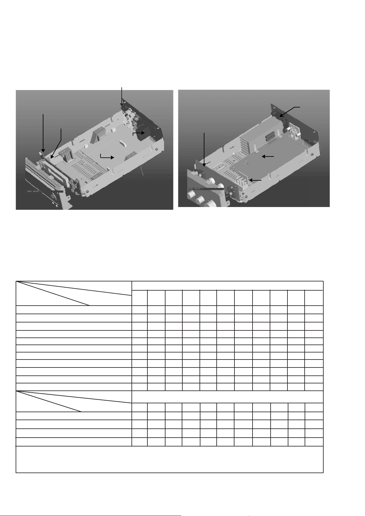
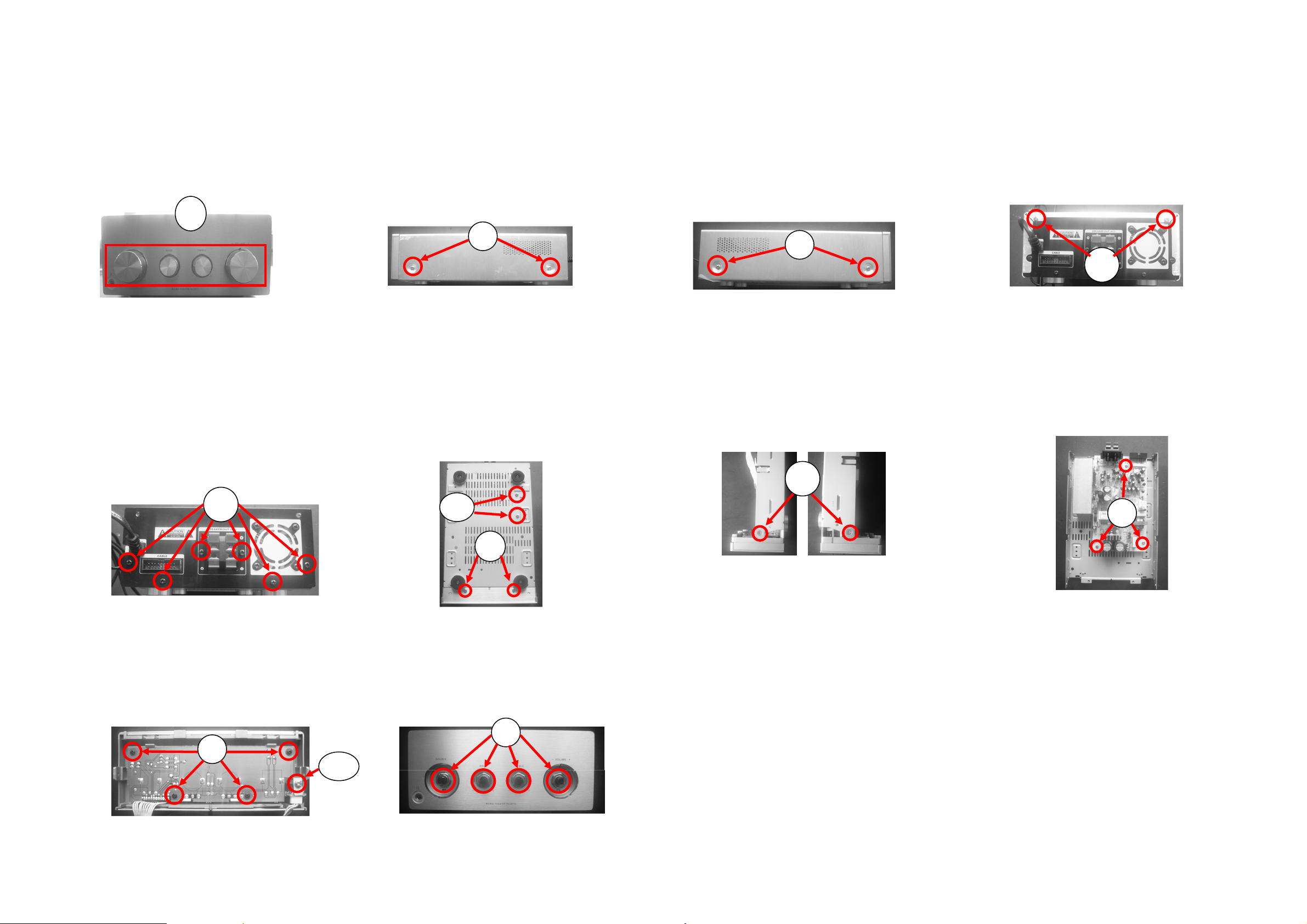
Location of PC Boards
√
1-1
AUX BOARD
VFD DISPLAY
BOARD
HEADPHONE
BOARD
DECODER BOARD
VERSION VARIATIONS
FAN
VOLUME BOARD
TUNER BOARD
POWER BOARD
110/220 CHANGING BOARD
:
Type /Versions:
Board in used:
Service policy
DISPLAY BOARD
USB BOARD
AXU BOARD
TUNER BOARD
HEADPHONE BOARD
DECODER BOARD
VOLUME BOARD
POWER BOARD
Type /Versions:
Features
Feature diffrence
RDS
VOLTAGE SELECTOR
ECO STANDBY - DARK
TDS
* TIPS : C -- Component Lever Repair.
M -- Module Lever Repair
-- Used
/05
/05
/12
/12
/37
/37
/55
/55
/58
/58
MCD772
/61
MCD772
/61
/79
/79
/93
C
M
M
M
M
M
M
M
/93
/94
/94
/96
/96
/98
/98

Specification
1-2
AMPLIFIER
Rated Output Power ........................ ..2 x 50W RMS
Signal-to-nois
Frequency response .......... 50Hz - 3 dB+/-2 20KHz
Aux Inpu
e ratio ........................... 65 dBA
t......................................0.5V RMS 47kohm
DISC
LaserType.......................................... Semiconductor
Disc Diamete
Suppo
DVD,DVD-R,DVD-
Audi
o DAC .......................................24Bits / 44.1kHz
Total Harmonic Distortion..................... <0.1%(1kHz)
Frequency Respons
S/N Ratio
r............................................ 12cm/8cm
rt Disc ..............................................................
RW,DVD+RW,CD-DA,MP3,CD-RW
e ............50Hz - 3dB+/-2 20KHz
n ....................................................≥65dBA
TUNER
FMTuning Range.............................87.5 – 108 MHz
Tuning grid ......................................................50KHz
Sensitivity
– Mono, 50dB S/N Ratio ..................................... 5u V
– Stere
o, 46dB S/N Ratio................................ 100uV
Selectivit
Imag
Total Harmonic Distortion................................... <3%
Signal to Noise Ratio
y ........................................................ >28dB
e Rejection ..............................................>25dB
n .................................. >50dBA
SPEAKERS
Speaker Impedance ................................................ 4ohm
ker Driver, base...................................................4.5"
Spea
ker Driver, tweeter .............................................. 3"
Spea
Frequency Respons
e ....................50Hz -3dB+/-2 20KHz
GENERAL INFORMATION
Total Output power ..................................... 10 0 W RMS
AC Power.....................................220-230V / 50Hz/60Hz
Ope
ration Power Consumption ................................. 55W
by Power Consumption .....................................<4W
Stand
Eco Stand
Headphon
US
by Power Consumption ..............................<1W
e Output ................................ 2X15mW 32ohm
B Direct ...................................................... Version 1.1
Dimensions
– Main unit (w x h x d) ........................... 248x280x105mm
– Speaker box (w x h x d)..................... 206x170x270mm
Weight
– With Packing ........................................................9 KG
– Main Unit .............................................................. 3.5KG
– Speaker box ........................................................3.3KG
Specifications and external appearance are
subject to change without notic
e.
e
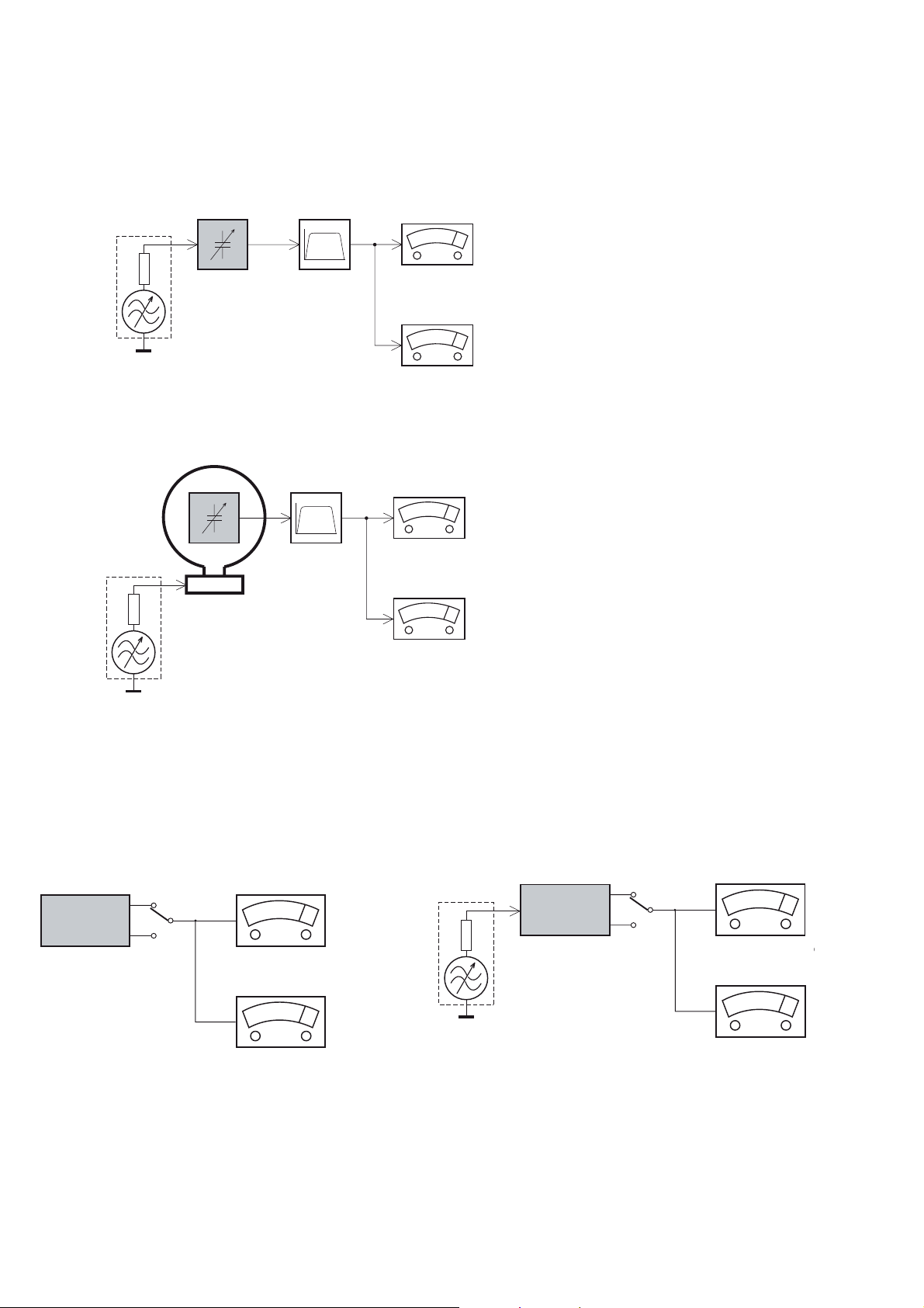
MEASUREMENT SETUP
Tuner FM
1-3
Bandpass
LF Voltmeter
e.g. PM2534
RF Generator
e.g. PM5326
DUT
250Hz 15kHz
e.g. 7122 707 48001
R =50:
S/N and distortion meter
e.g. Sound Technology ST1700B
Use a bandpass filter to eliminate hum (50Hz, 100Hz) and disturbance from the pilottone (19kHz, 38kHz).
Tuner AM (MW,LW)
RF Generator
e.g. PM5326
R =50:
DUT
Frame aerial
e.g. 7122 707 89001
Bandpass
250Hz 15kHz
e.g. 7122 707 48001
LF Voltmeter
e.g. PM2534
S/N and distortion meter
e.g. Sound Technology ST1700B
To avoid atmospheric interference all AM measurements have to be carried out in a Faraday´s cage.
Use a bandpass filter (or at least a high pass filter with 250Hz) to eliminate hum (50Hz, 100Hz).
CD
Use Audio Signal Disc
(replaces test disc 3)
DUT
L
R
SBC429 4822 397 30184
S/N and distortion meter
e.g. Sound Technology ST1700B
LEVEL METER
e.g. Sennheiser UPM550
-
Recorder
Use Universal Test Cassette CrO2 SBC419 4822 397 30069
or Universal Test Cassette
LF Generator
e.g. PM5110
Fe SBC420 4822 397 30071
DUT
L
R
S/N and distortion met
e.g. Sound Technology ST170
LEVEL METER
e.g. Sennheiser UPM550
with FF-filter
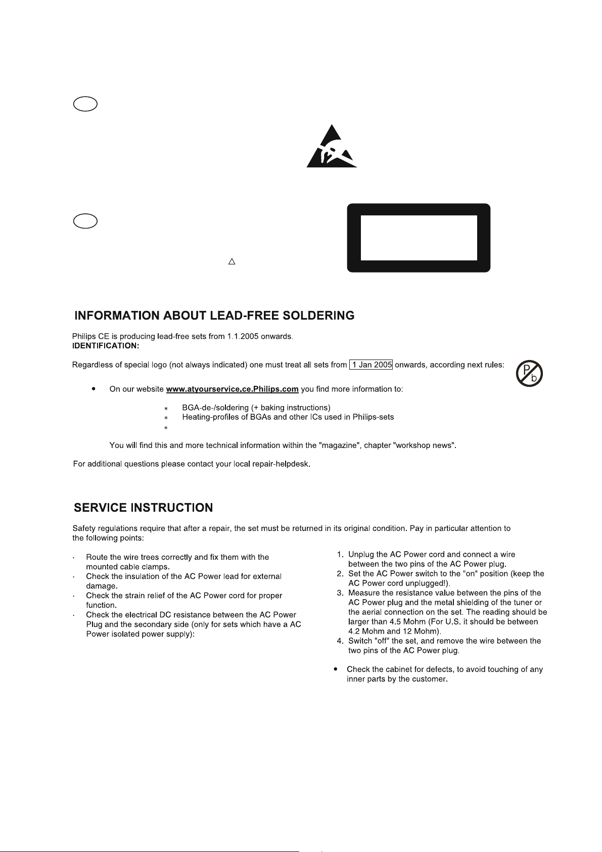
SERVICE AIDS
1-4
GB
All ICs and many other semi conductors are
susceptible to electrostatic discharges (ESD).
Careless handling during repair can reduce life
drastically.
When repairing, make sure that you are
connected with the same potential as the mass
of the set via a wrist wrap with resistance.
Keep components and tools also at this
potential.
WARNING
GB
Safety regulations require that the set be restored to its original
condition and that parts which are identical with those specified,
be used
Safety components are marked by the symbol
!
.
ESD
CLASS 1
LASER PRODUCT
Lead free
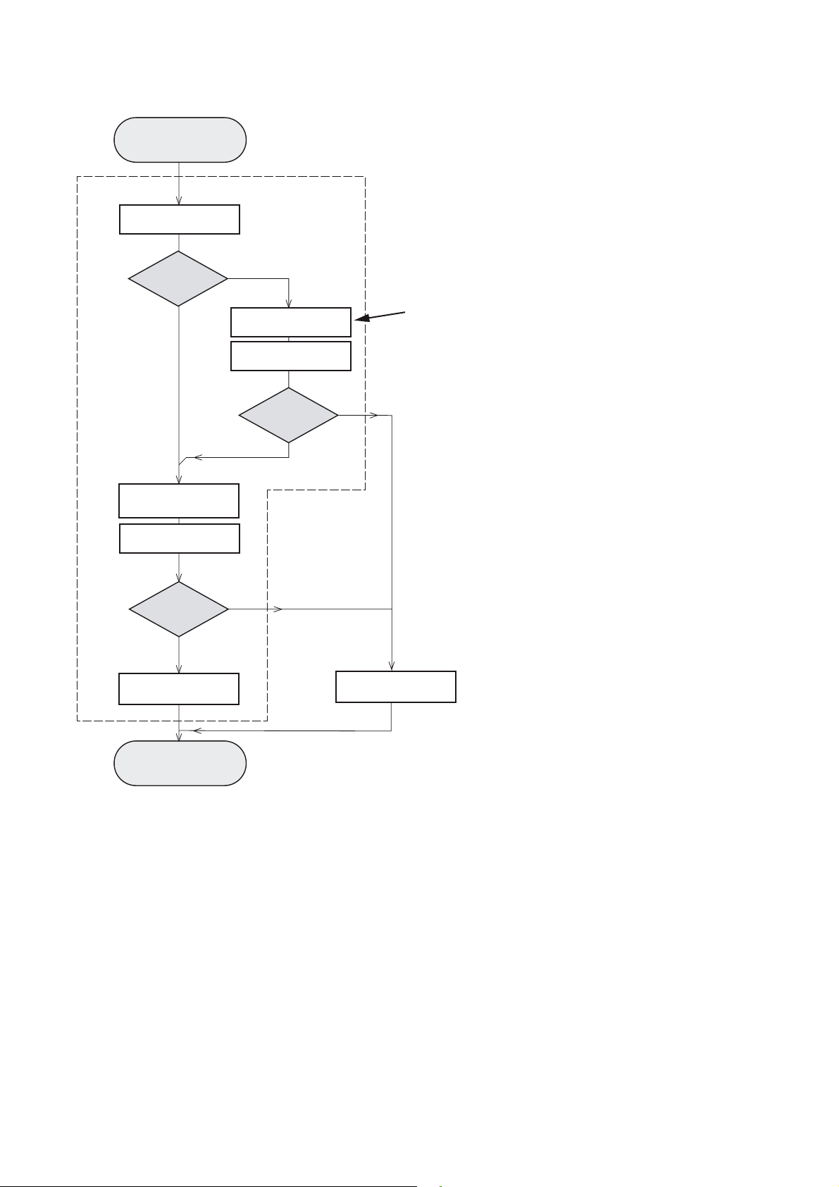
INSTRUCTIONS ON CD PLAYABILITY
Customer complaint
"CD related problem"
Set remains closed!
check playability
1
1-
playability
ok ?
Y
Play a CD
for at least 10 minutes
check playability
playability
ok ?
Y
N
"fast" lens cleaning
check playability
playability
ok ?
N
3
N
Y
For flap loaders (= access to CD drive possible)
cleaning method
4 is recommended
add Info for customer
"SET OK"
2
return set
1 4 For description see following pages
Exchange CDM
INSTRUCTIONS ON CD PLAYABILITY
1-
1
PLAYABILITY CHECK
For sets which are compatible with CD-RW discs
use CD-RW Printed Audio Disc ....................7104 099 96611
TR 3 (Fingerprint)
TR 8 (600μ Black dot) maximum at 01:00
• playback of these two tracks without audible disturbance
playing time for: Fingerprint t10seconds
Black dot from 00:50 to 01:10
• jump forward/backward (search) within a reasonable time
For all other sets
use CD-DA SBC 444A..................................4822 397 30245
TR 14 (600μ Black dot) maximum at 01:15
TR 19 (Fingerprint)
TR 10 (1000μ wedge)
• playback of all these tracks without audible disturbance
playing time for: 1000μ wedge t10seconds
Fingerprint t10seconds
Black dot from 01:05 to 01:25
• jump forward/backward (search) within a reasonable time
4
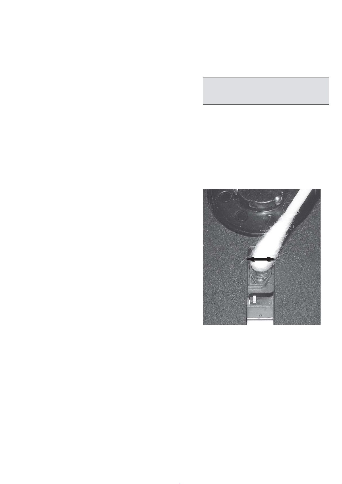
LIQUID LENS CLEANING
Before touching the lens it is advised to clean the
surface of the lens by blowing clean air over it.
This to avoid that little particles make scratches on
the lens.
Because the material of the lens is synthetic and coated
with a special anti-reflectivity layer, cleaning must be done
with a non-aggressive cleaning fluid. It is advised to use
“Cleaning Solvent
The actuator is a very precise mechanical component and
may not be damaged in order to guarantee its full function.
Clean the lens gently (don’t press too hard) with a soft and
clean cotton bud moistened with the special lens cleaner.
The direction of cleaning must be in the way as indicated in
the picture below.
2
CUSTOMER INFORMATION
It is proposed to add an addendum sheet to the set which
informs the customer that the set has been checked
carefully - but no fault was found.
The problem was obviously caused by a scratched, dirty or
copy-protected CD. In case problems remain, the customer
is requested to contact the workshop directly.
The lens cleaning (method 3) should be mentioned in the
addendum sheet.
The final wording in national language as well as the printing
is under responsibility of the Regional Service Organizations.

Software Version Check & Upgrade
Upgrade software
1.Downloading the software form Philips support website
http://www.philips.com/support
2.Load the CD Disc or USB with software,when it is loading,
the TV screen showing as below:
Upgrade File detected
Upgrade?
Press PLAY to start
Upgrading
Waiting half to one minute,till the TV screen showing disappear.
Turnoff electrical source and reopen.
3.Press SYSTEM on the remote open menu, press Left or Right to select “Preference
Page”, TV screen showing as below:
--Preference Page-TV type PAL
Audio CHI English
Subtitle CHI French
Disc menu CHI Spanish
Parental Chinese
Japanese
Default Korean
Russian
Tjai
2-1
Press Up or Down to select “Default” on remote, Press OK to exit reset.
Software upgrade finish.
Software check
Input password “811502” on remote, TV screen showing as below:
MCD772 / xxxx
Ver :
mm dd yyyy
Date
hh : mm : ss
Time
Region code
x
CPU version check
1.Keep press PLAY/PAUSE and STOP buttons,plug into the power cord at one time,
TV showing as below:
MCD772 Vxx
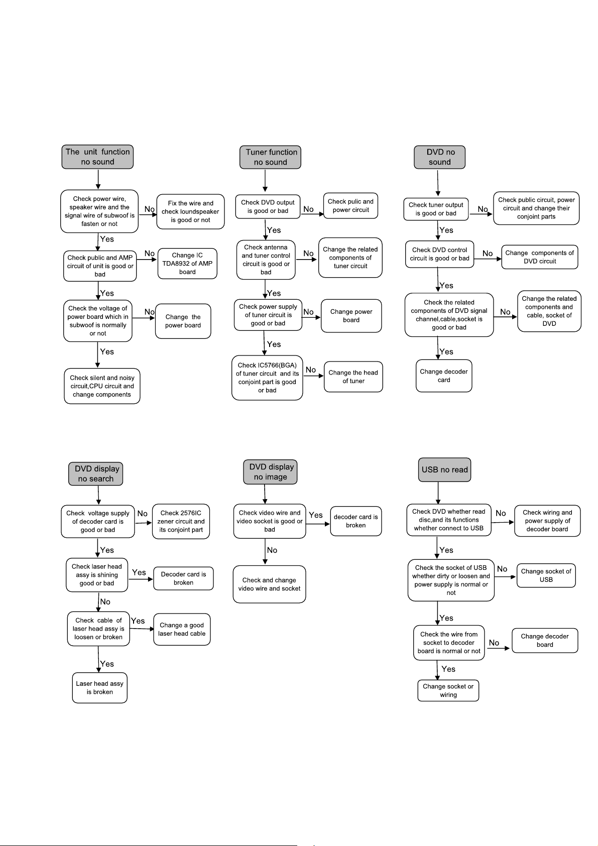
Malfunction follow check chart
2-2
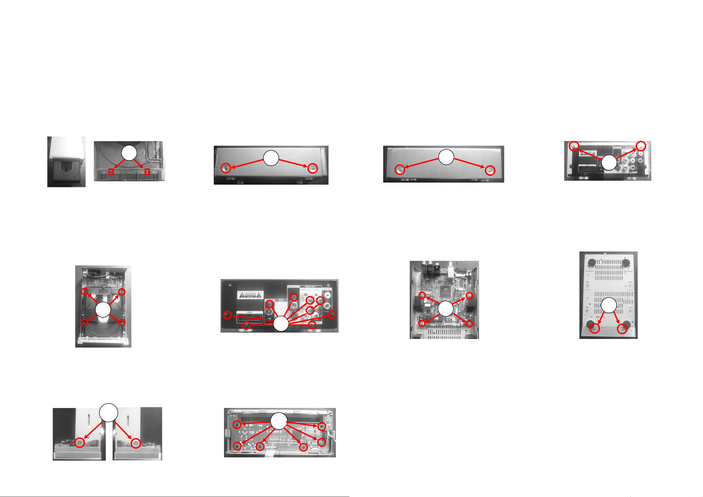
Disassembly Diagram-DVD Part
3-1 3-1
A.
A
ol
T
dn
o kc
t no
nru
h
ut
neht
b
ur
f
,ffo nr
t
r
e
e
b
r ,
ef
D
evome
A
3 swercs nesooL .E ×
CP4(
er
ot )S
V
D evom
AW
P01
DVD nepo ,rewop e
.rood
o ecalp owt ezirp
f
o
d DV
.ro
.
redaol D
B.
fel
L
o t
er
cs nesoo
O
T revoc f
)SCP2(IN0.6×0.3
hci
ol
hw sw
XR
T
t detac
eh
0
8 K
10
TTS 7-
C
.
L
gir
t
o
h
N0
×
.6
s nes
oo
e
v
f
oc
P2(I
C
B
.G
soo
F
L .
0
1-T
PTT
S
mer
ercs ne
0
.3 P5.1
1X
X0.
3 01-T
nap raer evo
PILIHP sw
BA 0.6
XR
T S
,
R
)SCP4(BA 0.0
OT
X
)SCP5(3
ot
.le
O
ooL
t
c
sw
er
r
T
.)S
cihw
S
7-T XRO
C
s
3
rcs nes
×
we
c
ed
evomer o
rao
b redo
d
h
t detacol h
e
3
1
0.
0
8 KTT
0
t ×
o
s
erc
esooL .D
n
p
.6
voc
e
OT
revoc
)
C
IN0
S
P2(
.
r
a
col hcihw sw
t
S 0
-T XR
1
dna ,
ht
r ne
fo kcab de
.3 KTT
0
pot ecomoe
D
P
)SC
4(MB5
.
s
.
ooL
H
ev
er
o
m
ot
s
c
r
s ne
tob
×
3
we
ot
B5
.
revoc m
P2(
S
TTM
)
C
E
G
H
F
I
3
tenibac edis
×
ol hci
hw swercs nesooL .
F
5
2(TTM
eht detac
)SCP
.
ooL .J × )SC
nes
6.2 swercs
ob yalpsid evomer ot
P6(AP
8
.dra
I
J
Disassembly Diagram-AMP Part
3-2 3-2
ercs nesooL .D
eh
A
.SCP4 bonk lanoitcnuf evomeR .
t fo thgir
.)SCP2(IN 0.6X0.3 0108
t detacol hcihw swercs nesooL .B
S 7-T XROT revoc po
KTT
w
swercs nesooL .C
detacol hcih
-
7
XROT revoc pot fo tfel eht
T
.)SCP2(IN 0.6X0.3 0108 KTTS
kcab
BTT
S
sw
voc pot fo
XROT re
CP2(IN 0.6X0.3
detacol hcihw
01-T
.)S
A
B
C
D
de
tacol hcihw swercs nesooL .G
CP
2 ).
×MB
3 swercs nesooL .H
5 ( SCP3 )
t
aob
PMA evomer o
.dr
BA
1X0.3 P5.1 P
0.0
p raer
.lena
T
,)SCP2(3
01-T XROT SPILIHP swercs nesooL .E
TT
XR
S
O
evomer ot )SCP4( 3BA 0.6X0.3 01-T
oL .F × T
s nes
o
evomer ot
b
ooL .1F
s
t
evo
mer o
r
3 sw
erc
motto
cs ne
wer
3 s
.rotaida
B
.r
( S
TM
5
evoc
×HTB6(
)
CP2
3
tenibac edis × TT
CP2
S
)
MF
5 ( S
E
o
oL .
I ×
r
H
t
nes
me
evo
.
ooL
1
sw
6.2
ercs
b emulov
sw
3
ercs nes
pdaeh evomer o
I
.drao
×
AP8
( S
AB8 ( S
.dra
ob enoh
CP4 ) ot
CP1 )
G
1
F
H
F
)SCP4(bonk lanoitcnuf fo swercs nesooL .J
.
J
1I
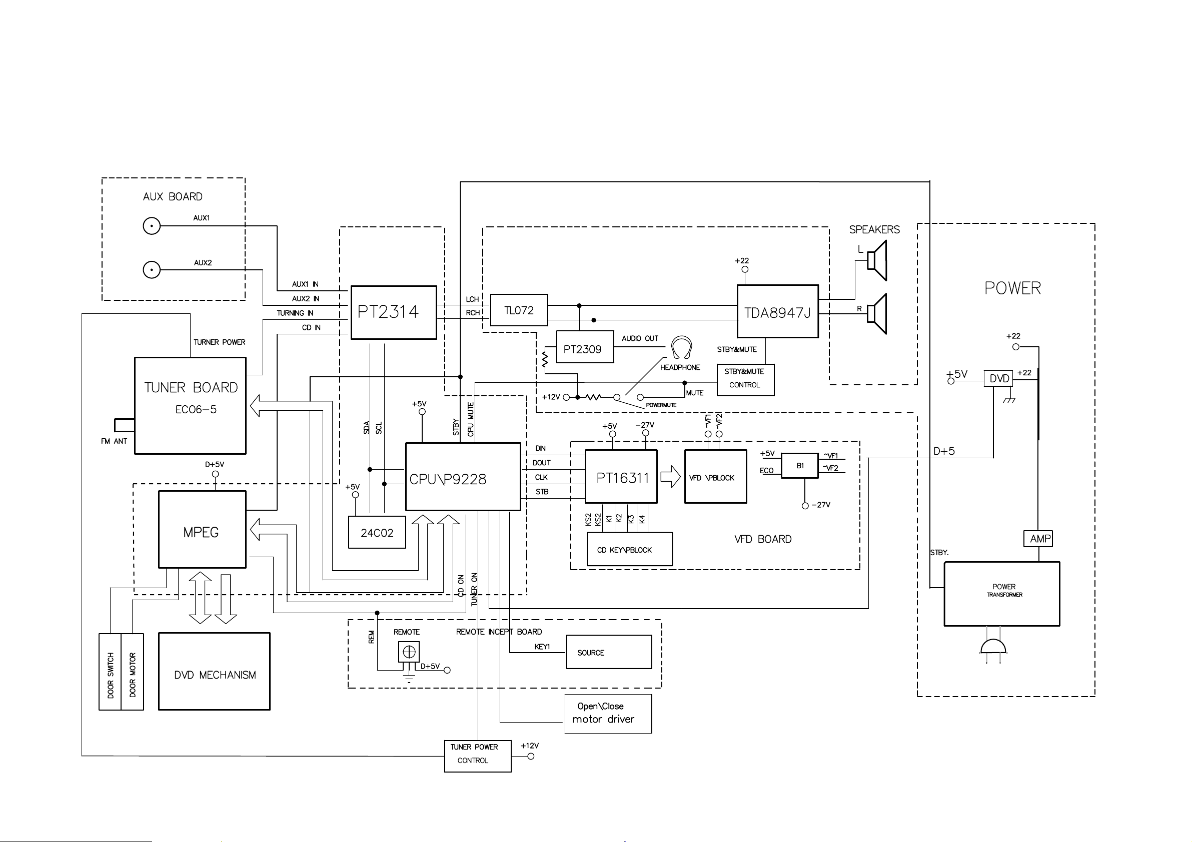
Block Diagram
4-1 4-1
MPEG
DIP 42
IC101
VFD101
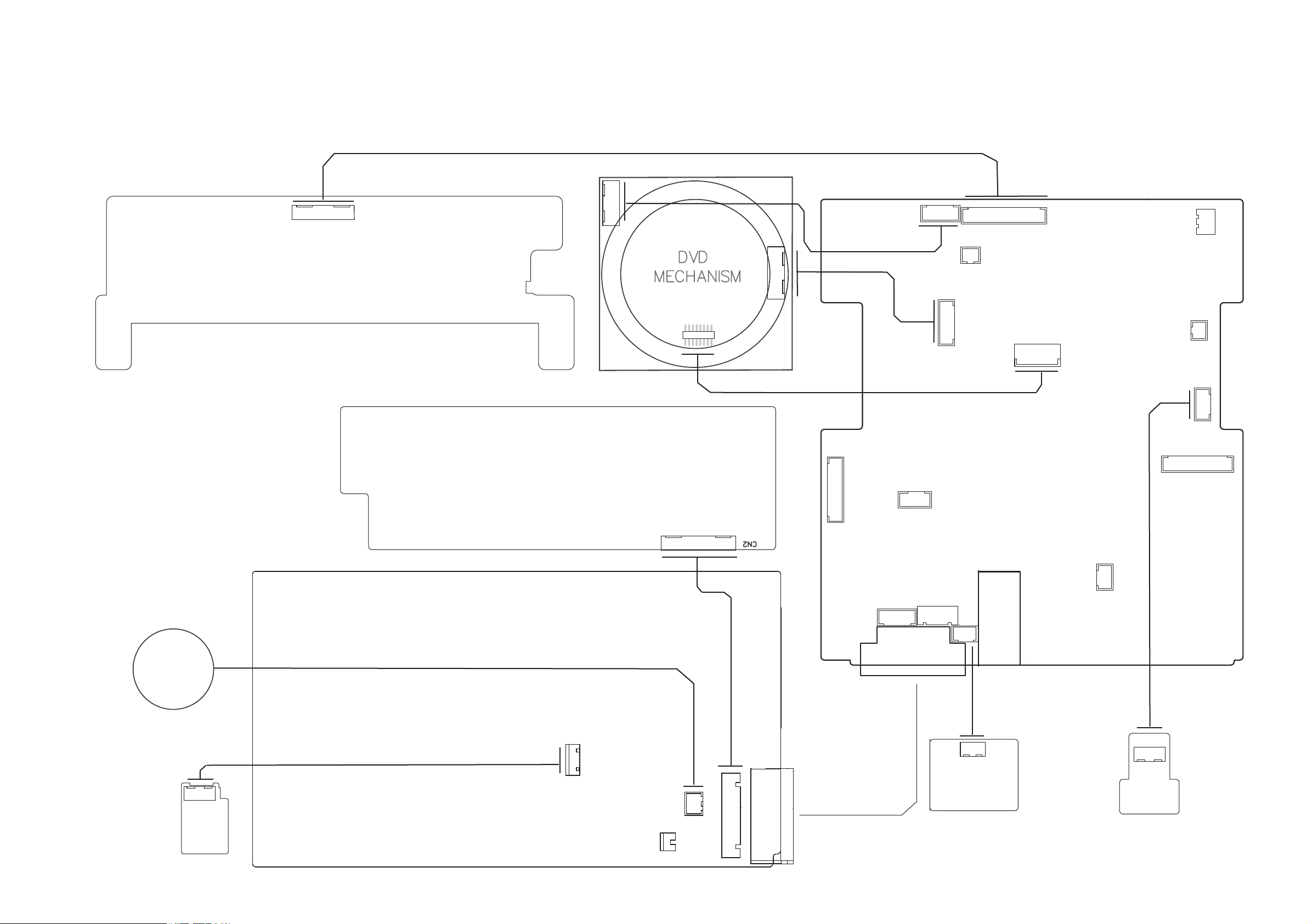
Wiring Diagram
ATAD
BTS
2FV
1FV
MER
KLC
42-
5+
VFD BOARD
CN101
4-24-2
J9
-M
+M
DNG
WS_ESOLC
WS_NEPO
1FV
2FV
ETOMER
V5UPC
V72-
DNG
KLC_SD
J7
1BTS_SD
TAD_SD
A_TOR
DNG
B_TOR
+1M
-1M
J12
-DEL
MOC
J15
J1
SPSP+
L MIT
GND
SL-
SL+
CON1
FFO/NO_BAD
DNG
J13
+5V_USB
USB+
-BSU
DNG
FAN
HEADPHONE
BOARD
ETUM
0R
0L
DNG
AC IN
VOLUME BOARD
POWER BOARD
POW181B (HIGHPASS CIRCUIT)
AGND
L0
R0
HP-MUTE
CON5
GND
LED
CON4
A_NUF
B_NUF
FAN
GND
DEL
SSAB
ELBERT
CON3
DNG
V5+
V21A
CON2
J3
J6
GND
TX_IPOD/SCL
RX_IPOD/SDA
POD_DET
R_ POD/BT
L_ POD/BT
AGND_IPOD/BT
DNG
A_TOR
B_TOR
POD_V DEO
I5V
33VD
DXR
DNG
DXT
MPEG BOARD
EJS89S772
J2
J5
TRACS_LDVD
TRACS_RDVD
TRACS_SBVC
DNG
#SBVC/BGR
TRACS_U/B
TRACS_Y/G
TRACS_V/R
DNG
9:61
J4
CON6
FUN_A
FUN_B
LED
TREBLE
BASS
REMOTE
D-GND
A12V
+5V
D-GND
ROT_A
ROT_B
STB
J11
J8
TUNNER
TUOL
TUOR
1ETUM
A_DNG
YBDNATS
DNG
DNG
V22_CCV
YBDNATS
J10
J14
A_DNG
NIL_XUA
NIR_XUA
CN501
R
L
DNG
AUX BOARD
OPTICAL
GND
PO_CCV
USB BOARD
SUBV
CN301
-D
+D
U-DNG
 Loading...