

Philips MCD-705 Service manual

Version 1.0
MCD705
© 3141 785 30630
Service Manual
DVD Micro System
all versions
Published by LX 0539 Service Audio Printed in The Netherlands Subject to modification
©
Copyright 2005 Philips Consumer Electronics B.V. Eindhoven, The Netherlands
All rights reserved. No part of this publication may be reproduced, stored in a retrieval
system or transmitted, in any form or by any means, electronic, mechanical, photocopying,
or otherwise without the prior permission of Philips.
Handling chip components ............................................................1-1
Information about lead-free soldering............................................1-2
Technical specification...................................................................2-1
Service tools..................................................................................2-1
Service measurement setup..........................................................2-2
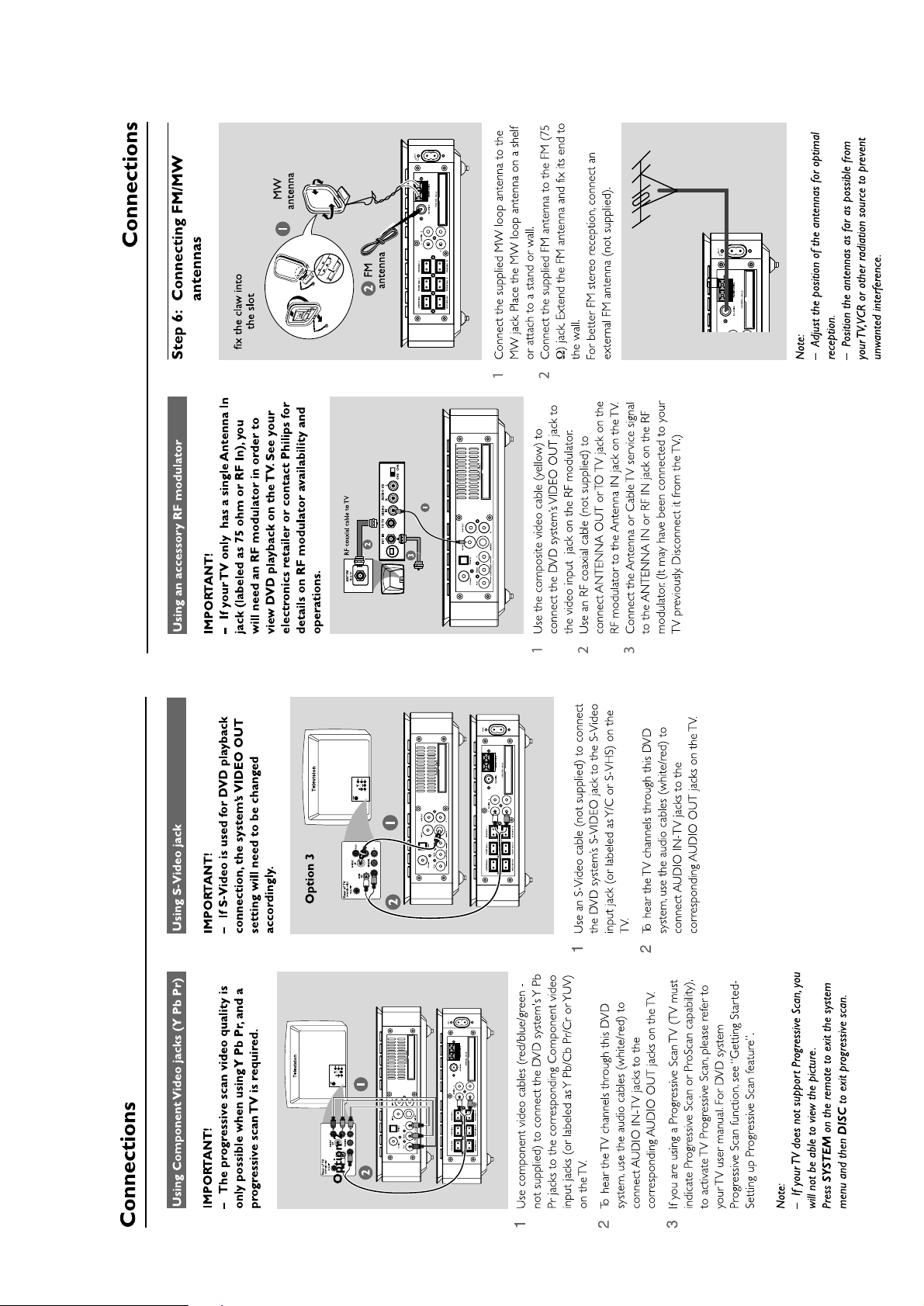
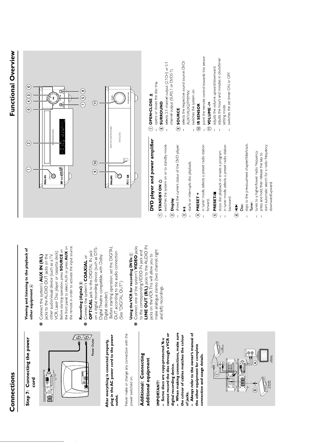
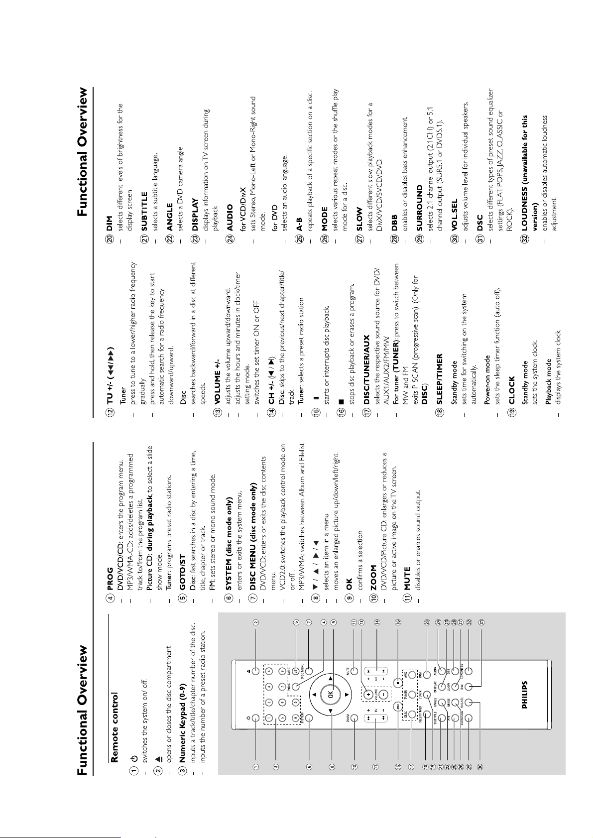
Connections and controls......................................................3-1...3-4
Disassembly diagram............................................................4-1...4-2
Software version and upgrading....................................................5-1
Set block diagram..........................................................................5-2
Set wiring diagram.........................................................................5-3
VFD BOARD
circuit diagram ..........................................................................6-1
layout diagram..........................................................................6-2
TUNER BOARD
circuit diagram ..........................................................................7-1
layout diagram..........................................................................7-2
layout diagram-amp box pcb assy............................................7-2
AMP BOARD
circuit diagram ..........................................................................8-1
layout diagram..........................................................................8-2
CPU BOARD
circuit diagram ..........................................................................9-1
layout diagram..........................................................................9-2
ALC VOLUME BOARD
circuit diagram ........................................................................10-1
layout diagram........................................................................10-2
DVD MPEG BOARD
circuit diagram..............................................................11-1...11-5
layout diagram........................................................................11-6
Exploded view diagram................................................................12-1
Mechanical partslist.....................................................................12-2
Electrical partslist...............................................................13-1...13-3
TABLE OF CONTENTS
CLASS 1
LASER PRODUCT
1 - 1
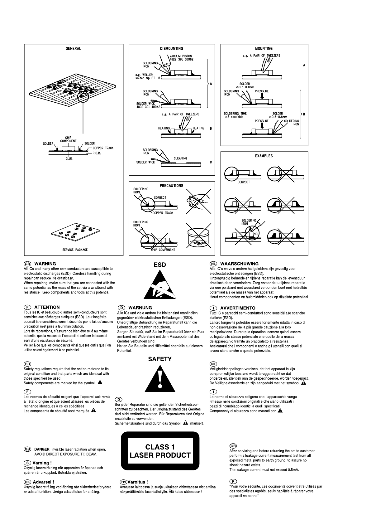
HANDLING CHIP COMPONENTS
1 - 2
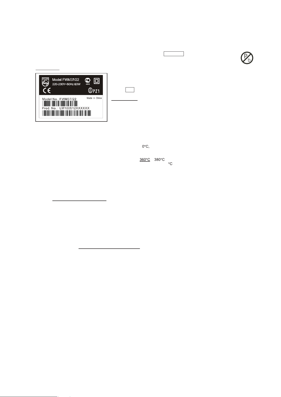
INFORMATION ABOUT LEAD-FREE SOLDERING
Philips CE is producing lead-free sets from 1.1.2005 onwards.
IDENTIFICATION:
Regardless of special logo (not always indicated) one must treat all sets from 1 Jan 2005 onwards, according next rules:
Example S/N:
Bottom line of typeplate gives a 14-digit S/N. Digit 5&6 is the year, digit 7&8 is the week number,
so in this case 2005 wk12
So from 0501 onwards = from 1 Jan 2005 onwards
Im portant note
: In fact also product s of year 2004 must be treated in this way as long as
you avoid mixing solder-alloys ( leaded/ lead -free). So best to always use SAC305 and the
higher temperatures belong to this.
Due to lead-free technology some rules have to be respected by the workshop during a repair:
• Use only lead-free solder alloy Philips SAC305 with order code 0622 149 00106. If lead-free solder-paste is required, please contact
the manufacturer of your solder-equipment. In general use of solder-paste within workshops should be avoided because paste is not
easy to store and to handle.
• Use only adequate solder tools applicable for lead-free solder alloy. The solder tool must be able
o To reach at least a solder-temperature of 40
o To stabilize the adjusted temperature at the solder-tip
o To exchange solder-tips for different applications.
• Adjust your solder tool so that a temperature around
− is reached and stabilized at the solder joint. Heating-time of the
solder-joint should not exceed ~ 4 sec. Avoid temperatures above 400 otherwise wear-out of tips will rise drastically and flux-fluid
will be destroyed. To avoid wear-out of tips switch off un-used equipment, or reduce heat.
• Mix of lead-free solder alloy / parts with leaded solder alloy / parts is possible but PHILIPS recommends strongly to avoid mixed
solder alloy types (leaded and lead-free).
If one cannot avoid or does not know whether product is lead-free, clean carefully the solder-joint from old solder alloy and re-solder
with new solder alloy (SAC305).
• Use only original spare-parts listed in the Service-Manuals. Not listed standard-material (commodities) has to be purchased at
external companies.
• Special information for BGA-ICs:
- always use the 12nc-recognizable soldering temperature profile of the specific BGA (for de-soldering always use the lead-free
temperature profile, in case of doubt)
- lead free BGA-ICs will be delivered in so-called 'dry-packaging' (sealed pack including a silica gel pack) to protect the IC against
moisture. After opening, dependent of MSL-level seen on indicator-label in the bag, the BGA-IC possibly still has to be baked dry.
(MSL=Moisture Sensitivity Level). This will be communicated via AYS-website.
Do not re-use BGAs at all.
• For sets produced before 1.1.2005 (except products of 2004), containing leaded solder-alloy and components, all needed spare-parts
will be available till the end of the service-period. For repair of such sets nothing changes.
• On our website www.atyourservice.ce.Philips.com
you find more information to:
∗
BGA-de-/soldering (+ baking instructions)
∗
Heating-profiles of BGAs and other ICs used in Philips-sets
You will find this and more technical information within the "magazine", chapter "workshop news".
For additional questions please contact your local repair-helpdesk.
SERVICE INSTRUCTION
1. Unplug the AC Power cord and connect a wire
between the two pins of the AC Power plug.
2. Set the AC Power switch to the "on" position (keep the
AC Power cord unplugged!).
3. Measure the resistance value between the pins of the
AC Power plug and the metal shielding of the tuner or
the aerial connection on the set. The reading should be
larger than 4.5 Mohm (For U.S. it should be between
4.2 Mohm and 12 Mohm).
4. Switch "off" the set, and remove the wire between the
two pins of the AC Power plug.
Safety regulations require that after a repair, the set must be returned in its original condition. Pay in particular attention to
the following points:
· Route the wire trees correctly and fix them with the
mounted cable clamps.
· Check the insulation of the AC Power lead for external
damage.
· Check the strain relief of the AC Power cord for proper
function.
· Check the electrical DC resistance between the AC Power
Plug and the secondary side (only for sets which have a AC
Power isolated power supply):
• Check the cabinet for defects, to avoid touching of any
inner parts by the customer.

2 - 1
TECHNICAL SPECIFICATIONS
GENERAL
Mains voltage
-/93
-/93
:
:
Mains frequency
220V
-/61
:
220V
50 Hz
-/61
:
60 Hz
Battery
remote
:3 V (AAA x 2)
Power consumption
normal 52 W
Standby
:< 4 W
Dimension (W x H x D)
::147 x 232 x 223 mm
Weight
(excluding packing and batteries)
: 5.4 Kg
AMPLIFIER
Output power mains
subwoofer
mains
subwoofer
::5 x 20W
1 x 50W
Speaker impedance
:5 x 8 ohm
1 x 4 ohm
Frequency response
:
:
20 Hz - 20 kHz (±3dB)
TUNER - FM SECTION
Tuning range : 87.5 - 108 MHz
IF frequency
: 10.7 MHz ± 0.02 MHz
Sensitivity
:< 22 dBf at 26dB
Selectivity
300kHz : > 3 3 dB
IF Rejection
:> 60 dB
Image Rejection
:> 25dB
Distortion
:< 3 %
:
Tuning Grid
100/50K Hz
Tuning Grid
9/10K Hz
TUNER - AM SECTION
Tuning range :
:
:
531 - 1602 kHz
IF frequency
450 kHz ± 1 kHz
Sensitivity
:
≤ 3.25 mV/m at 26dB
:
Selectivity S9/300kHz
:> 12 dB
:
IF rejection
:> 24 dB
Distortion
:< 5%
:
Image rejection
:> 20 dB
<
DVD / MP3 / CD
Laser Type : Semiconductor
Disc Diameter : 12cm / 8cm
Video Decoding : MPEG-2 / MPEG-1
Signal System : PAL / NTSC
Video S/N : 53 dB (min.)
Composite Video Output : 1.0 Vp-p, 75
S-Video Output : Y - 1.0 Vp-p, 75
C - 0.286 Vp-p, 75
Audio DAC : 24 Bits / 96 kHz
Frequency Response : 20 Hz - 20 kHz
Channel Unbalance : <
±
2dB
THD Noise : 0.5%
No. of programmable tracks : 20
Signal-to-noise ratio : 70 dBA
Channel separation : 40 dB (1 kHz)
: 35 dB (16 kHz)
: 30 dB (20 kHz)
To
tal harmonic distortion : < 0.02% (1 kHz)
SERVICE TOOLS
Audio signal disc SBC 429.......................................................................4822 397 30184
Playability test disc SBC 444
...................................................................4822 397 30245
Test disc 5 (disc without errors ) +
Test disc 5A (disc with dropout errors, black spots and fingerprints)
SBC 426/426A.....................................................................4822 397 30096
Burn in test disc (65 min. 1kHz signal at -30 dB level without “pause”)
.....4822 397 30155
anti-static table mat
large 1200x650x1.25mm 4822 466 10953
small 600x650x1.25m 4822 466 10958
anti-static wristband
4822 395 10223
connection box (3 press stud connections, 1MΩ) 4822 320 11307
extendible cable (2m, 2MΩ, to connect wristband to connection box) 4822 320 11305
connecting cable (3m, 2MΩ, to connect table mat to connection box) 4822 320 11306
earth cable (1MΩ, to connect any product to mat or to connection box) 4822 320 11308
KIT ESD3 (combining all 6 prior products - small table mat) 4822 310 10671
wristband tester 4822 344 13999
AVAILABLE ESD PROTECTION EQUIPMENT
2 - 2
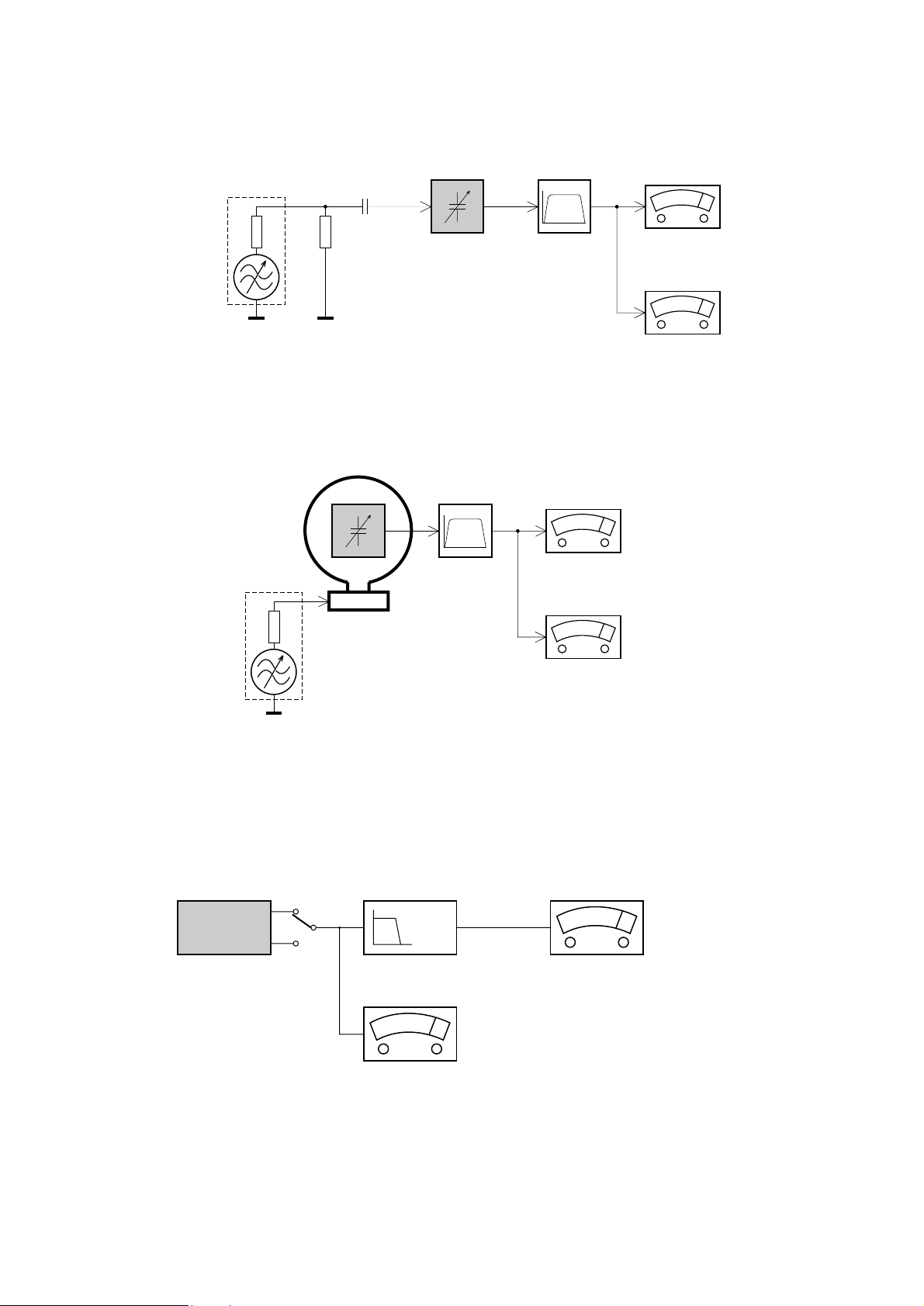
SERVICE MEASUREMENT
Bandpass
250Hz-15kHz
e.g. 7122 707 48001
LF Voltmeter
e.g. PM2534
DUT
RF Generator
e.g. PM5326
S/N and distortion meter
e.g. Sound Technology ST1700B
Tuner SW
To avoid atmospheric interference all AM-measurements have to be carried out in a Faraday«s cage.
Use a bandpass filter (or at least a high pass filter with 250Hz) to eliminate hum (50Hz, 100Hz).
Ri=50Ω
Aerial replacement
Capacitor
R=50Ω
Bandpass
250Hz-15kHz
e.g. 7122 707 48001
LF Voltmeter
e.g. PM2534
DUT
S/N and distortion meter
e.g. Sound Technology ST1700B
Frame aerial
e.g. 7122 707 89001
Tuner AM (MW,LW)
To avoid atmospheric interference all AM-measurements have to be carried out in a Faraday«s cage.
RF Generator
e.g. PM5326
Ri=50Ω
Low pass filter 22kHz
L
R
LEVEL METER
e.g. Sennheiser UPM550
with FF-filter
S/N and distortion meter
e.g. Sound Technology ST1700B
DUT
CD
Use Audio Signal Disc SBC429 4822 397 30184 (replaces test disc 3)
L.P.F. = 13
th
order filter 4822 395 30204
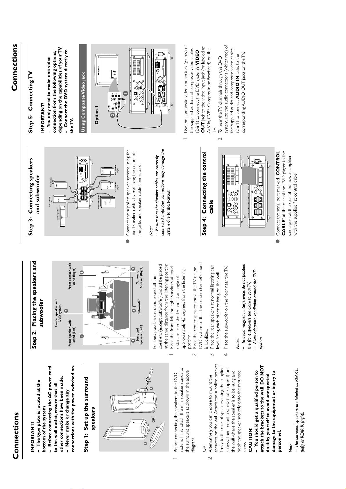
3 - 1
CONNECTION AND CONTROLS
3 - 2
CONNECTION AND CONTROLS
3 - 3
CONNECTION AND CONTROLS
3 - 4
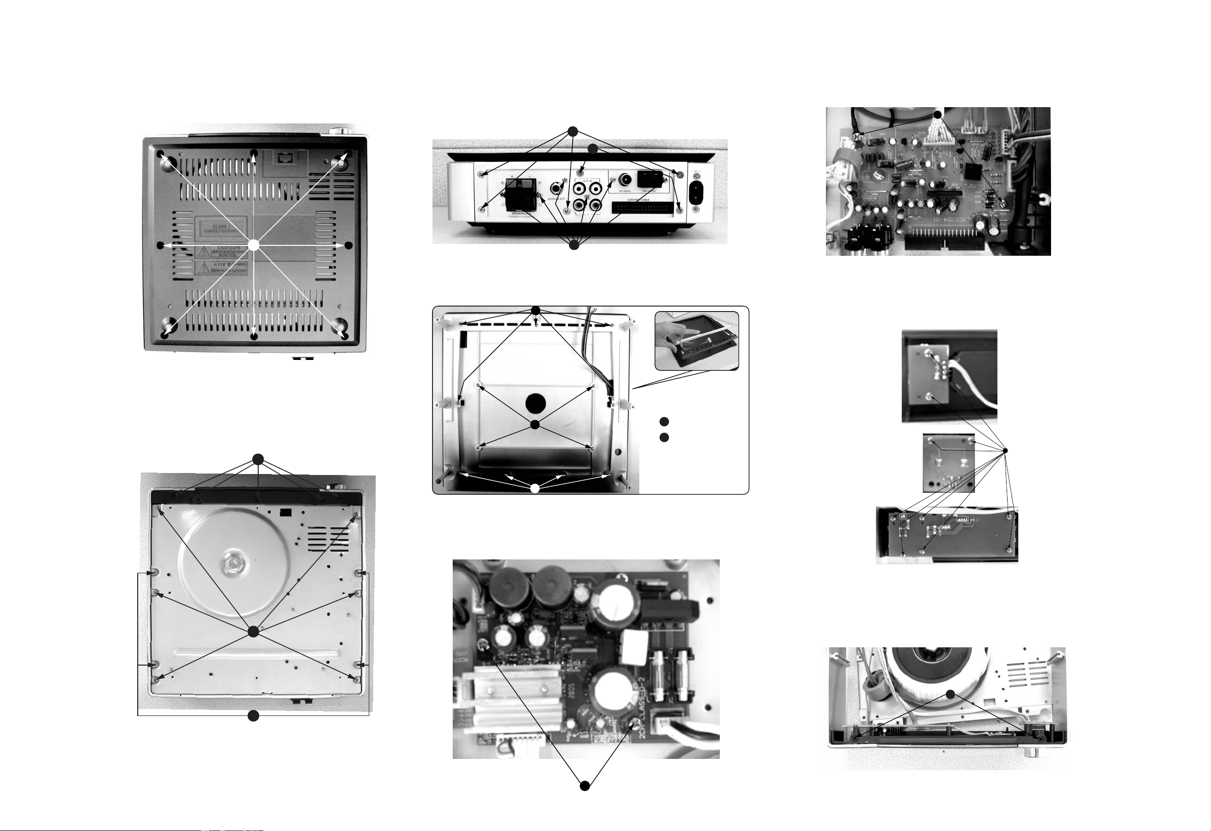
4
CONNECTION AND CONTROLS
4 - 14 - 1
A
B1
B2
C1
C2
D1
D2 D3
F
G
H
I
J
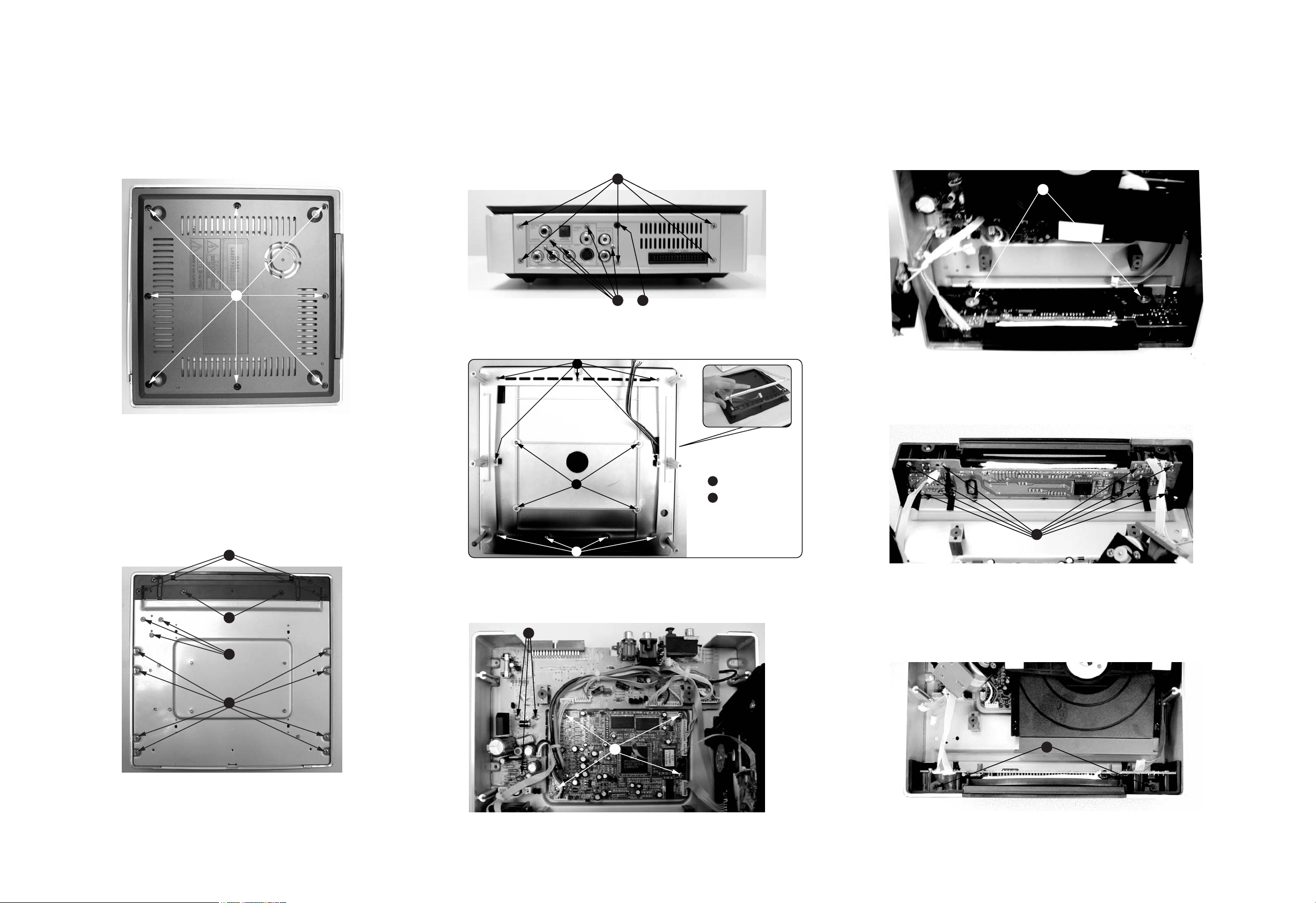
A.Remove Bottom Cover
A1.remove screws M2.5x4(8pcs)
B*.remove screws M3x10(8pcs) and M3x8(3pcs)
C*.remove screws M3x8(4pcs) and T3x4(2pcs)
E1
E2
E2
E1
*M2.5x5
E2
*M2.6x8
D.Remove Back Panel
D*remove screws T3x4(5pcs)and M3x10(5pcs)and T3x8(1pc)
E. Remove Top Cover
G. Remove DVD Rom and then remove DVD Decoder Card Assy
I.Remove VFD board assy
H.Remove Slid Plank
I.Remove Side metal Plate
DISASSEMBLY DIAGRAM - DVD PART
4 - 2 4 - 2
A
C
B1
B2
D1
D2
D3
F
G
H
I
A.Remove Bottom Cover
A1.remove screws M2.5x4(8pcs)
B*.remove screws M3x10(6pcs) and T3x10(4pcs)
C*.remove screws T3x4(5pcs)
D.Remove Back Panel
D*remove screws T3x4(4pcs)and T3x8(2pcs)and M3x10(6pcs)
E. Remove Top Cover
F. Remove AMP Board Assy
E1
E2
E2
E1
*M2.5x5
E2
*M2.6x8
H.Remove AMP Front board assy
G.Remove ALC Volume board assy
I.Remove Side metal Plate
DISASSEMBLY DIAGRAM - AMP PART
 Loading...