

Philips MCD-295, MCD-290 Service Manual
DVD Micro System
MCD290,MCD295
all versions
Service Manual
TABLE OF CONTENTS
Repair policy of PCBS ............................................................1-1
Technical specification...................................................................2-1
Service tools ..................................................................................2-1
Service measurement setup..........................................................2-2
Connections and controls......................................................3-1...3-4
Troubleshooting.............................................................................3-5
Disassembly diagram ............................................................4-1...4-2
Service test program......................................................................5-1
Set block diagram..........................................................................5-2
Set wiring diagram.........................................................................5-3
DISPLAY BOARD
circuit diagram ..........................................................................6-1
layout diagram ..........................................................................6-2
©
Copyright 2005 Philips Consumer Electronics B.V. Eindhoven, The Netherlands
All rights reserved. No part of this publication may be reproduced, stored in a retrieval
system or transmitted, in any form or by any means, electronic, mechanical, photocopying,
or otherwise without the prior permission of Philips.
CASSETTE BOARD
circuit diagram ..........................................................................7-1
layout diagram ..........................................................................7-2
MAIN BOARD(for MCD290)
circuit diagram ..................................................................8-1...8-2
layout diagram..................................................................8-3...8-4
MAIN BOARD(for MCD295)
circuit diagram ..................................................................8-5...8-6
layout diagram..................................................................8-7...8-8
MPEG BOARD
circuit diagram ..................................................................9-1...9-3
layout diagram ..........................................................................9-4
Exploded view diagram................................................................10-1
Mechanical partslist .....................................................................10-2
Electrical partslist(for MCD290).........................................11-1...11-2
Electrical partslist(for MCD295).........................................11-3...11-4
Revision list..................................................................................12-1
CLASS 1
LASER PRODUCT
Published by LX 0628 Service Audio Printed in The Netherlands Subject to modification
Version 1.2
© 3141 785 30662
REPAIR POLICY OF PCBS
√
√
1 - 1
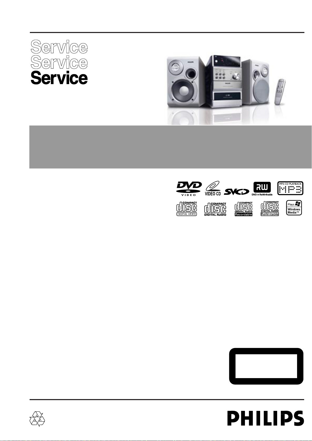
VERSION VARIATIONS:
Type /Versions:
Board in used:
Service policy
DISPLAY BOARD
MAIN BOARD
CASSETTE BOARD
MEPG BOARD
Type /Versions:
Features
RDS
VOLTAGE SELECTOR
ECO STANDBY - DARK
* TIPS : C -- Component Lever Repair.
M -- Module Lever Repair
-- Used
Feature diffrence
/05
C
C
C
M
/05
/12
C
C
C
M
/12
/58
C
C
C
M
/58
MCD290/MCD295
/79 /98
C
C
C
C
C
C
M
M
MCD290/MCD295
/79 /98
2 - 2
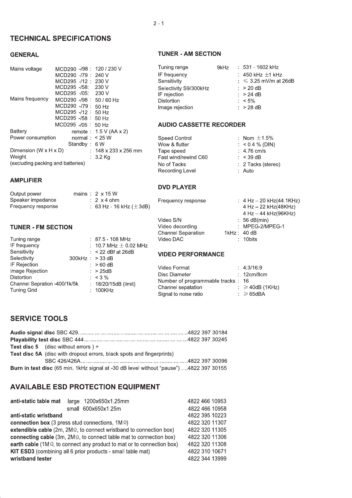
SERVICE MEASUREMENT
Bandpass
250Hz-15kHz
e.g. 7122 707 48001
LF Voltmeter
e.g. PM2534
DUT
RF Generator
e.g. PM5326
S/N and distortion meter
e.g. Sound Technology ST1700B
Tuner SW
To avoid atmospheric interference all AM-measurements have to be carried out in a Faraday«s cage.
Use a bandpass filter (or at least a high pass filter with 250Hz) to eliminate hum (50Hz, 100Hz).
Ri=50Ω
Aerial replacement
Capacitor
R=50Ω
Bandpass
250Hz-15kHz
e.g. 7122 707 48001
LF Voltmeter
e.g. PM2534
DUT
S/N and distortion meter
e.g. Sound Technology ST1700B
Frame aerial
e.g. 7122 707 89001
Tuner AM (MW,LW)
To avoid atmospheric interference all AM-measurements have to be carried out in a Faraday«s cage.
RF Generator
e.g. PM5326
Ri=50Ω
Low pass filter 22kHz
L
R
LEVEL METER
e.g. Sennheiser UPM550
with FF-filter
S/N and distortion meter
e.g. Sound Technology ST1700B
DUT
CD
Use Audio Signal Disc SBC429 4822 397 30184 (replaces test disc 3)
L.P.F. = 13
th
order filter 4822 395 30204
FM Antenna
It is unnecessary to connect the FM pigtail
antenna since it is fixed to the main unit.
Adjust the FM antenna for optimal FM stereo
reception.
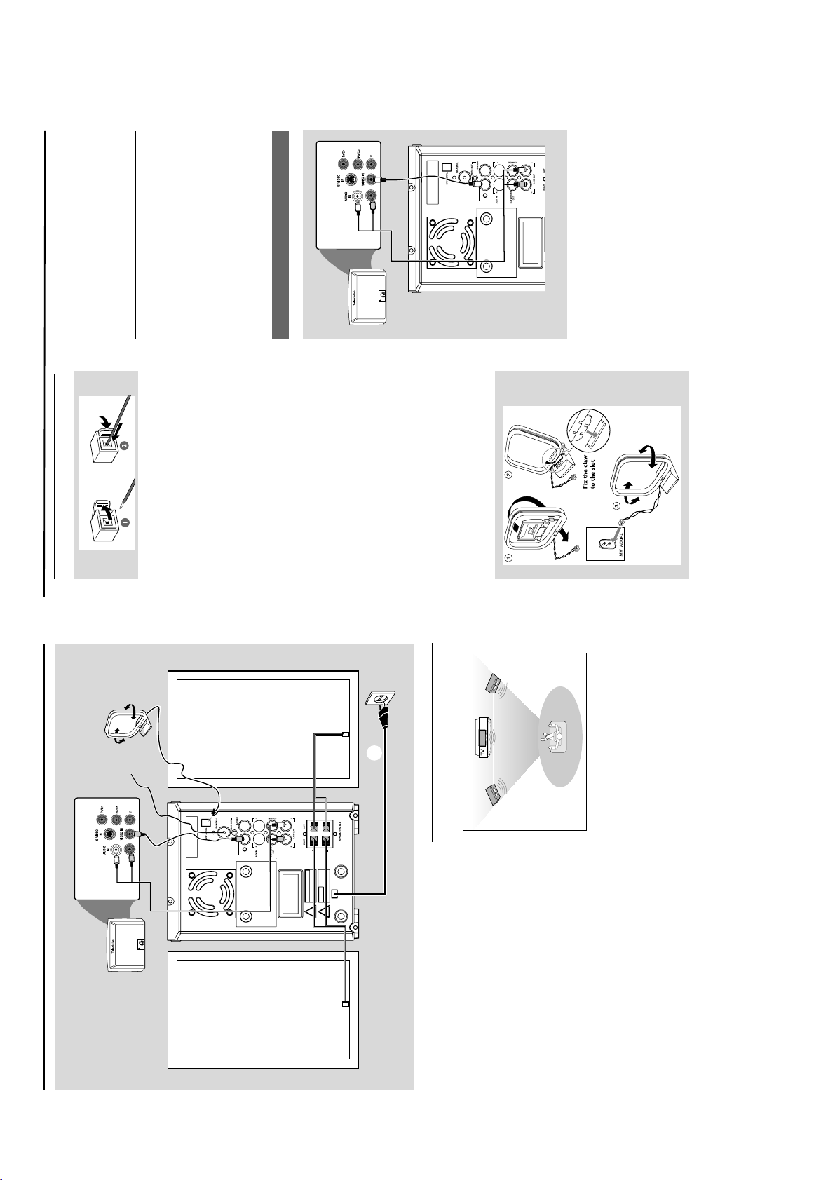
Step 4: Connecting TV
IMPORTANT!
–You only need to make one video
connection from the following options,
depending on the capabilities of your TV
system.
–Connect the DVD system directly to
the TV .
Using Video In jack (CVBS)
1 Use the composite video cable (yellow) to
connect the system's VIDEO jack to the video
input jack (or labelled as A/V In, Video In,
Composite or Baseband) on the TV set.
2 To hear the sound of this DV D Player through
your TV, use the audio cab les (white/red-not
supplied) to connect LINE OUT (L/R) jacks of
the DV D Player to the cor responding AUDIO
IN jacks on the TV.
Connections
Step 2: Connecting speakers
Connect the speak er wires to the SPEAKERS
terminals, right speaker to "RIGHT" and left
speaker to "LEFT", coloured (mar ked) wire to
"+" and black (unmarked) wire to "-". Fully inser t
the stripped por tion of the speaker wire into
the terminal as shown .
Notes:
– Ensure that the speaker cables are correctly
connected. Improper connections may damage the
system due to short-circuit.
–For optimal sound performance, use the
supplied speakers.
– Do not connect more than one speaker to any
one pair of +/- speaker terminals.
– Do not connect speakers with an impedance
lower than the speakers supplied. Please refer to
the SPECIFICATIONS section of this manual.
Step 3: Antenna connection
MW Antenna
Connect the supplied MW loop antenna to the
"MW AERIAL" terminal. Adjust the position of
the antenna for optimal reception.
Position the antenna as far as possib le from a TV,
VCR or other radiation source .
Connections
Step 1: Placing speakers
Front
speaker
( left )
Front
speaker
( right )
VIEWING AREA
Place the front left and right speakers at equal
distances from the TV set and at an angle of
approximately 45 degrees from the listening
position.
Notes:
–To avoid magnetic interference, do not position
the front speakers too close to your TV set.
– Allow adequate ventilation around the DVD
System.
IMPORTANT!
– The type plate is located at the rear of
the system.
– Before connecting the AC power cord
to the wall outlet, ensure that all other
connections have been made.
–Never make or change any
connections with the power switched on.
– The voltage selector located at the
bottom of this system is preset at
220V-240V from the factory. For
countries that operate at 110V-127V,
please adjust to 110V-127V before you
switch on the system.
To avoid overheating of the system, a
safety circuit has been built in. Therefore,
your system may switch to Standby
mode automatically under extreme
conditions. If this happens, let the system
cool down before reusing it (not available
for all ve rsions).
Speaker
(right)
Speaker
(left)
AC power cord
FM wire
antenna
MW loop
antenna
5
4
2
3
3 - 1
CONNECTION AND CONTROLS
3 - 2
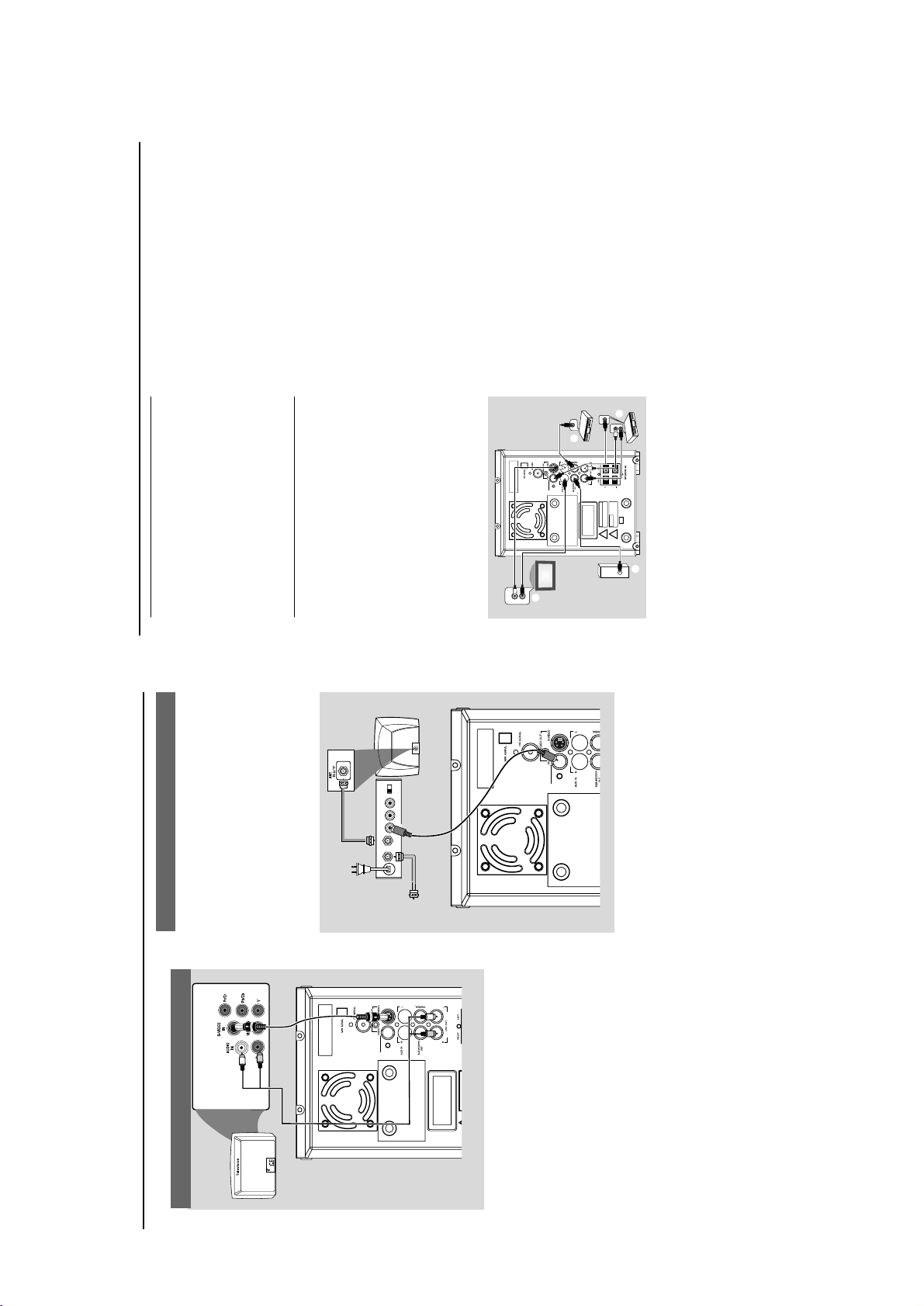
Using an accessory RF modulator
IMPORTANT!
– If your TV set only has a single
Antenna In jack (or labelled as 75 ohm or
RF In), you will need a RF modulator in
order to view the DVD playback via TV.
See your electronics retailer or contact
Philips for details on RF modulator
availability and operations.
1 Use the composite cable (yello w) to connect the
system's VIDEO jack to the video input jack on
the RF modulator .
2 Use an RF coaxial cable (not supplied) to
connect the RF modulator to your TV's RF jack.
Connections
Using S-Video In jack
1 Use the S-Video cable (not supplied) to connect
the system's S-VIDEO jack to the S-Video
input jack (or labelled as Y/C or S-VHS) on the
TV set.
2 To hear the sound of this DVD Player through
your TV, use the audio cables (white/red-not
supplied) to connect LINE OUT (L/R) jacks of
the DVD Player to the corresponding AUDI O
IN jacks on the TV.
AUDIO IN
R L
VIDEO
IN
TO TVANT IN
CH3 CH4
RF coaxial cable to TV
Back of RF Modulator
(example only)
Antenna or
Cable TV signal
Connections
Step 5: Connecting the power
cord
IMPORTANT!
–Never make or change any connection
with the power switched on.
After ev er ything is connected properly, plug in
the AC power cord to the power outlet.
Optional: Connecting additional
equipment
IMPORTANT!
– Some discs are copy-protected. You
cannot record the disc through a VCR or
digital recording device.
–When making connections, make sure
the colour of cables matches the colour
of jacks.
–Always refer to the owner's manual of
the other equipment for complete
connection and usage details.
DIGITAL IN
C
AUDIO
INPUT
AUDIO OUT
L
R
AUDIO IN
L
R
VIDEO IN
A
B
D
Viewing and listening to the playback of
other equipment A
Connect the system's AUX IN (R/L) jacks to
the AUDIO OUT jacks on the other audio/visual
device (such as a TV, VCR, Laser Disc player or
cassette deck).
Before starting operation, press SOURCE on
the front panel to select AUX or press AUX on
the remote in order to activate the input source .
Using the VCR for recording DVDs B
Connect one of the system's VIDEO OUT
jacks to the corresponding VIDEO IN jack and
LINE OUT (R/L) jacks to the AUDIO IN jacks
on the VCR. This will allow you to make analogue
stereo (two channel, right and left) recordings.
Recording (digital) C
Connect the system's COAXIAL jack to the
DIGIT AL IN jack on a digital recording device
(such as DTS-Digital Theatre compatible, with
Dolby Digital decoder).
Before star ting oper ation, set the DIGITAL OU T
according to the audio connection. (See
"DIGITAL OUT". )
Connecting an active subwoofer D
Connect the DVD micro system's
SUBWOOFER OUT jack to the AU DIO
INPUT jack on an acti ve subwoofer (not
supplied).
CONNECTION AND CONTROLS
3 - 3
1
2
7
9
8
@
!
0
%
543
6
DISPLAY/ST
2 THEATHRE
#
$
1
2
#
7
0
™
£
3
)
(
*
8
9
&
$
%
!
@
0
7
568
^
4
∞
§
¡
•
ª
CONNECTION AND CONTROLS

3 - 4
Controls
6 DISC MENU (disc mode only)
–DVD/VCD : enter s or exits the disc contents
menu.
– VCD2.0: switches the pla yback control mode on
or off .
7 22/33
Tuner
– press to tune to a lower/higher radio frequency
gradually.
– press and hold, then release the key to star t
automatic search f or a r adio frequency
downward/upward.
Disc
– (not for MP3 CD) searches backward/forward in
a disc at different speeds.
–In DISC mode , to select a mo vement direction in
the disc menu or system menu bar.
8 3/4
–In DISC mode , to select a movement direction in
the disc menu or system menu bar.
9 OK
– to exit or conf irm the selection.
0 í/ë
–Disc: skips to the previous/next chapter/title/
track.
–Tuner : selects a preset radio station.
! STOP 9
–In DISC mode , to stop playback or clear a
program.
@ PLAY/PAUSE 2;
–In DISC mode , to start or interrupt playback.
# VOL +/-
– adjusts the vo lume upward/downward.
– adjusts the hours and minutes in clock/timer
setting mode .
–switches the set timer ON or OFF.
$ REPEAT
– to repeat a track/disc .
% SUBTITLE
– selects a subtitle language .
^ SLEEP
– to set the sleep (auto-off) timer function.
& LOUDNESS
– enables or disab les automatic loudness
adjustment.
* DSC
– selects different types of preset sound equalizer
settings (CLASSIC, JAZZ, POP or ROCK).
( DBB
–enables or disables bass enhancement.
)
MUTE
–to inter rupt or resume sound reproduction.
¡ DISPLAY (OSD)
–displays information on TV screen during
playback.
–FM: to set stereo or mono sound mode .
™ SLOW
– selects different slow pla yback modes for a VCD /
SVCD/DVD.
£ SHUFFLE
–to repeat playback of all tr acks in a random
order.
REPEA T A-B
–for VCD/CD : to repeat a specific section within
the same track.
–for DV D: to repeat a specific section in a disc .
∞
AUDIO
for VCD
– sets Stereo , Mono-Left or Mono-Right sound
mode.
for DVD
– selects an audio language .
§ TIMER
*– to set the timer.
≥ ZOOM
–DVD/VCD/Picture CD : enlarges or reduces a
picture or acti ve image on the TV screen.
• ANGLE
– selects a DV D camer a angle.
ª GOTO
–In DISC mode , to fast search in a disc by
entering a time, title, chapter or track.
Notes for remote control:
–First, select the source you wish to
control by pressing one of the source select
keys on the remote control (DISC or
TUNER, for example).
–Then select the desired function ( 2;, í,
ë for example).
≤
CONNECTION AND CONTROLS
Controls
Controls on the system
1
STANDBY ON y
–switches the system to standby/on.
2
iR sensor
–infrared sensor for remote control .
3
CLOCK
Standby mode
*– sets the system clock.
Playback mode
–displays the system clock.
4 PROGRAM
–DVD/VCD/CD/MP3-CD : enter s the program
menu.
–Picture CD : during playback, to select a slide
sho
w mode
.
–Tuner : progr ams preset r adio stations.
5 DISPLAY/ST
–Disc: to select disc information displ
ay mode .
–FM: to set stereo or mono sound mode .
6 Mode Selection
STOP 9 ............ In DISC mode , to stop pla yback
or clear a program.
PLAY/PAUSE 2;
................................. In DISC mode , to star t or
interrupt playback.
PRESETí/ë
Disc: skips to the previous/next chapter/title/
track.
Tuner : selects a preset radio station.
TUNING 22/33
Tuner
– press to tune to a lower/higher radio frequency
gradually.
– press and hold, then release the key to start
automatic search f or a radio frequency
downward/upward.
Disc
– searches fast backward/f orward in a disc .
7 Display screen
– to view the current status of the system .
8 SOURCE
– to select the respecti ve sound source : DISC
TUNER, TAPE or AUX.
9 LOUDNESS
– enables or disab les automatic loudness
adjustment.
0 DBB
– enables or disab les bass enhancement.
! DSC
– selects different types of preset sound equalizer
settings (CLASSIC, JAZZ, POP or ROCK).
@ VOLUME
– adjusts the volume upward/downward.
– adjusts the hour s and minutes in clock/timer
setting mode .
–in timer setting mode , switches the set timer ON
or OFF.
# n
– to connect a headphone .
$ OPEN•CLOSE3
– to open or close the disc door .
% Tape Deck Operation
RECORD ...starts recording.
PLAY 2 ............ starts playback.
SEARCHà / á fast rewinds/winds the tape .
STOP•OPENÇ0
................................. stops tape playback/recording;
opens the tape compartment.
PAU SEÅ .......interrupts recording or playback.
Controls on the remote control
1
y
–switches the system on/off.
2 Numeric Keypad (0-9)
–inputs a track/title/chapter number of the disc .
3 PROGRAM
–DVD/VCD/CD/MP3-CD : enter s the program
menu.
–Picture CD : during playback, to select a slide
show mode .
–Tuner : progr ams preset radio stations.
4 SOURCE
– to select the respecti ve sound source : DISC
TUNER, TAPE or AUX.
5 SYSTEM MENU (disc mode only)
– to enter or exit the system me nu bar.

3 - 5
Problem
Solution
The language for the sound or subtitle
cannot be changed when playing a DVD.
No image is output when a function is
selected.
Sound cannot be heard or is of poor
quality
Poor radio reception.
Recording or playback cannot be made
Left and right sound outputs are
reversed.
The remote control does not function.
The timer is not working
The Clock/Timer setting is erased
Multi-language sound or subtitle is not recorded
on the DVD.
Changing the language f or the sound or subtitle
is prohibited on the DVD.
Make sure the component is connected
cor rectly.
Press the correct function button for the input
source .
Adjust the volume .
Disconnect the headphones.
Check that the speakers are connected correctly.
Check if the stripped speaker wire is clamped.
If the system is in pause , slow motion or fast
forward/rev erse mode , press PLAY/PAUSE 2;
to resume the normal play mode .
Make sure the MP3-CD was recorded within 32-
256 kbps bit rate with sampling frequencies at
48 kHz, 44.1 kHz or 32 kHz.
Ensure that the DTS disc also supports Dolby
Digital output.
If the signal is too weak, adjust the antenna or
connect an external antenna for better
reception.
Increase the distance between the System and
your TV set or VCR.
Clean deck parts, see “Maintenance”.
Use only NORMAL tape .
Apply a piece of adhesive tape over the missing
tab space.
Check the speaker connections and location.
Point the remote control at the remote control
sensor of the unit.
Reduce the distance to the player.
Remove any possib le obstacles.
Replace the batter ies with new ones.
Check that the batteries are loaded correctly .
Set the clock correctly.
If recording is in progress, stop it
Power has been interrupted or the power cord
has been disconnected. Reset the clock/timer.
Troubleshooting
WARNING
Under no circumstances should you try to repair the system yourself, as this will
invalidate the warranty. Do not open the system as there is a risk of electric shock.
If a fault occurs, first check the points listed below before taking the system for repair. If
you are unable to remedy a problem by following these hints, consult your dealer or
Philips for help.
Problem
Solution
Troubleshooting
No power.
“NO DISC” is displayed.
No picture.
Distorted or poor picture.
The aspect ratio of the screen cannot be
changed even though you have set the TV
shape.
The DVD player does not start playback.
The DVD player does not respond when
buttons are pressed.
Check if the AC power cord is properly
connected.
Check if the disc is inserted upside down.
Wait until the moisture condensed at the lens
has cleared.
Replace or clean the disc , see “Maintenance”.
Use a readable disc or correctly recorded format
MP3-CD.
Select the appropriate video input mode on the
TV set.
Check if the TV set is switched on.
Check the video connection.
Check if the system is securely connected.
Sometimes a slight picture distortion may appear.
This is not a malfunction.
Clean the disc .
Connect the system to the S-video input of your
TV set.
The aspect ratio is fixed on the DVD disc.
The aspect ratio may not be changed for some
TV systems.
Insert a readable disc.
Check the disc type, color system and region
code .
Clean the disc .
Place the disc with the playback side down.
Press SYSTEM MENU to turn off the setup
menu.
Cancel the parental control rating function or
change the rating level.
Moisture has condensed inside the system.
Remove the disc and le ave the system turned on
for about an hour .
Disconnect the power plug from the jack, and
inser t again.
TROUBLESHOOTING
4 - 1
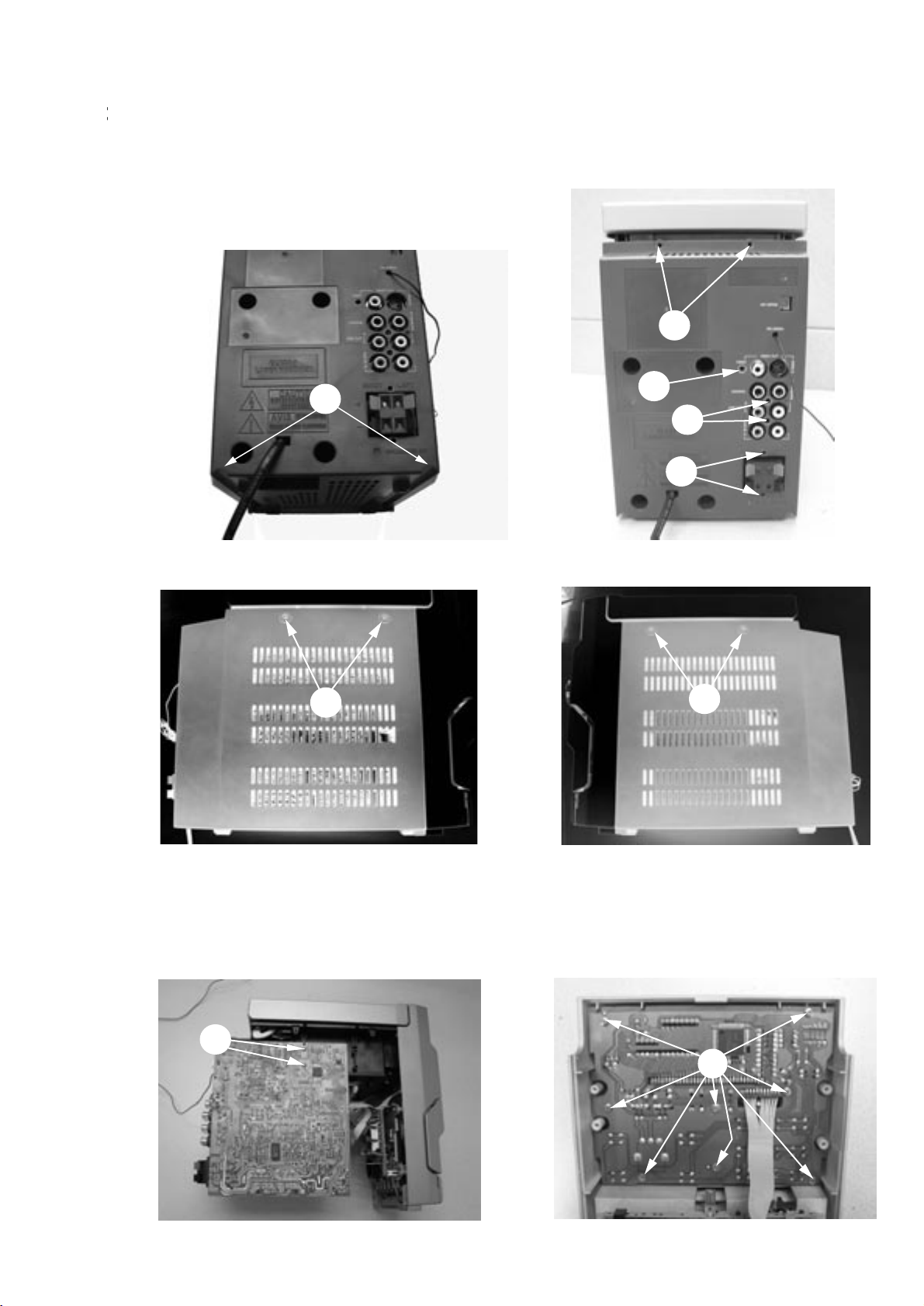
STEP A : Remove Rear Cabinet
- A1 : Remove 2 screws (SP3x12)
- A2 : Remove 4 screws (SP3x10)
- A3 : Remove 1 screws (SP3x10)
- A4 : Remove 2 screws (SP3x10)
STEP B :
Remove Main board and LCD board
- B1: Remove 2 screws (SP3x8)
A6
A7
- A5 : Remove 2 screws (SP3x10)
- A6 : Remove 2 screws (K3x10)
- A7 : Remove 2 screws (K3x10)
B1
B2
- B2: Remove 8 screws (SP2.5x8)
A5
A4
A3
A2
A1
DISASSEMBLY DIAGRAMS
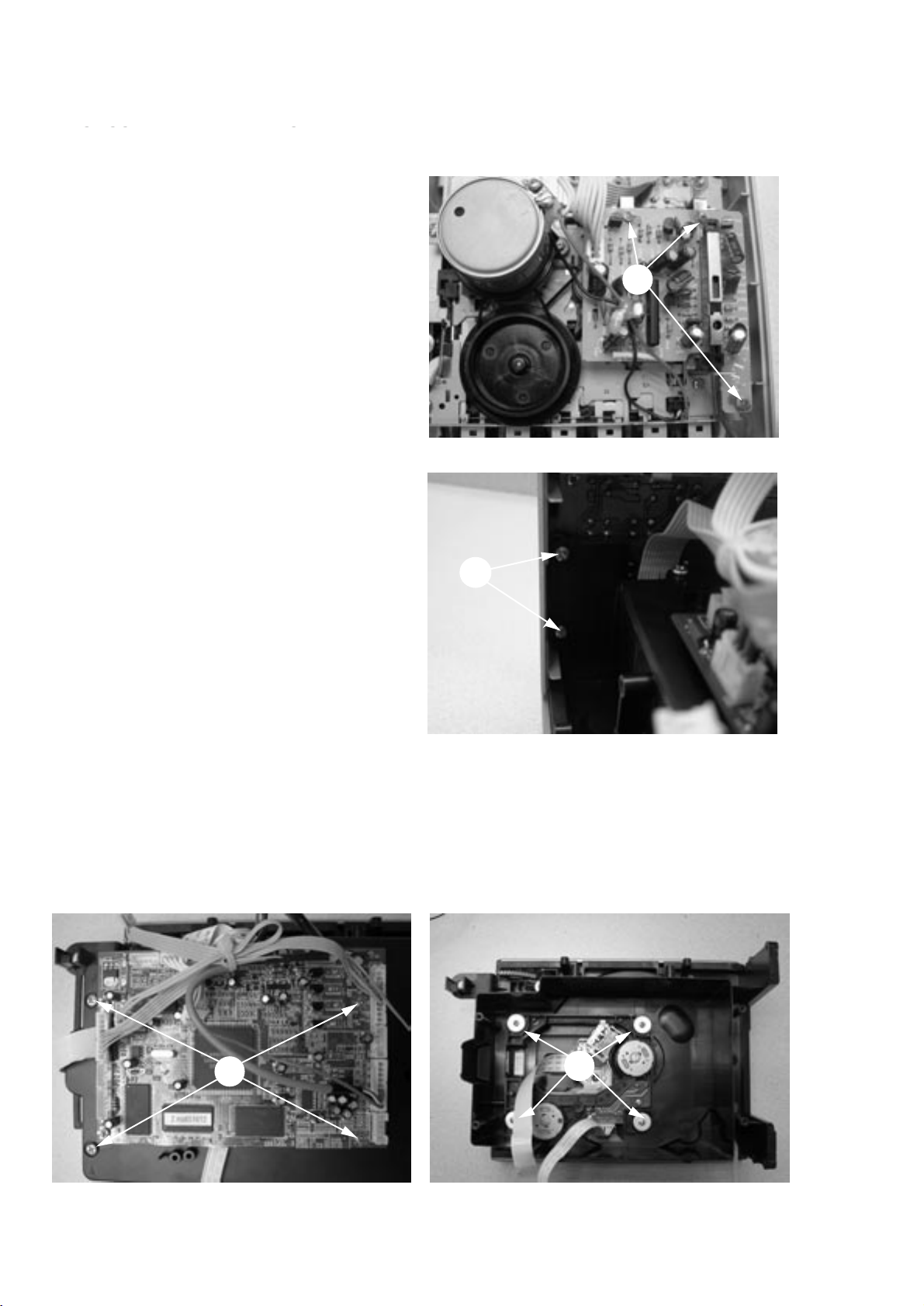
4 - 2
DISASSEMBLY DIADRAMS
STEP C :
Remove Cassette PCB Assy
- Remove 3 screws (K2x5)
STEP D :
Remove CD tray
- Remove 4 screws (SP3x10)
STEP E :
Remove DVD Mechaniam
- Remove DVD PC board 4 screws (SP2.5x6)
- Remove CD tray cover 4 screws (SP3x8)
- Remove DVD Mechaniam 4 screws(M2.5x10)
C1
D1
E3
E1
DISASSEMBLY DIAGRAMS
5 - 1
5 - 1
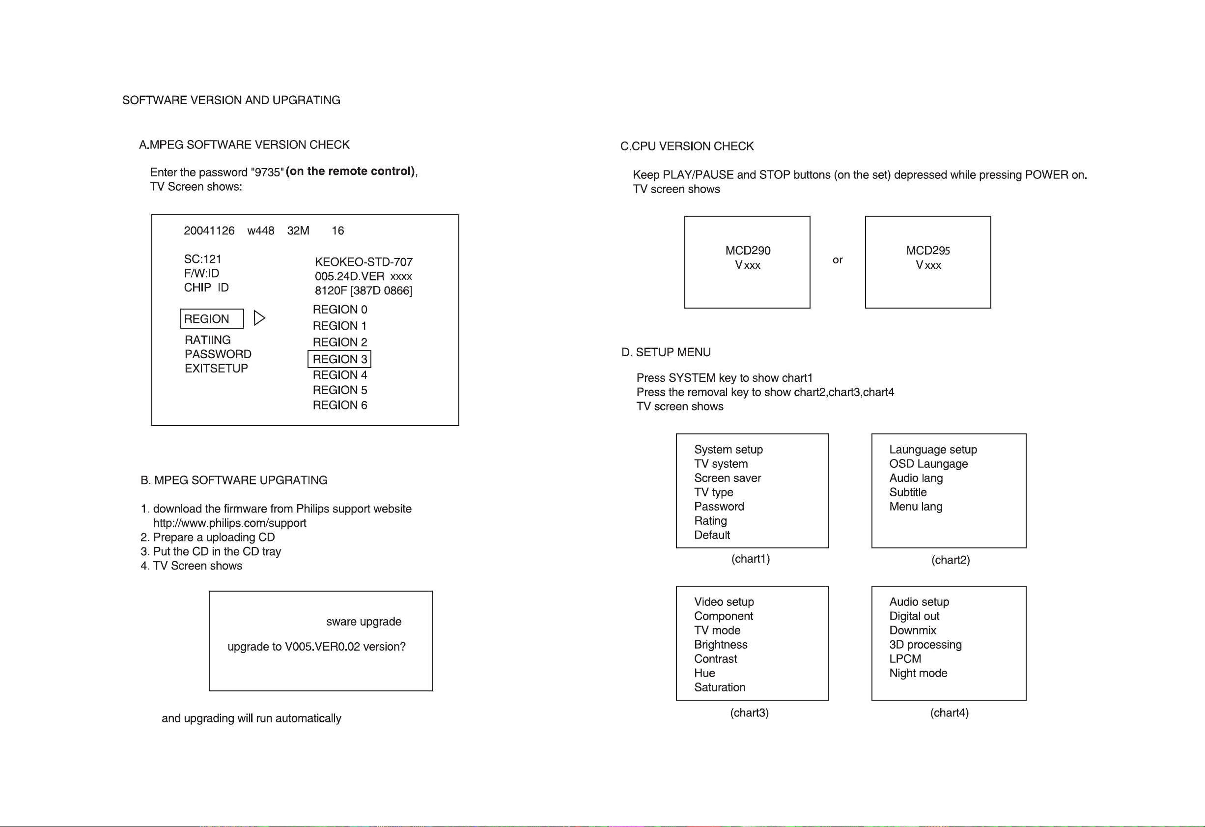
SOFTWARE VERSION AND CHECK
 Loading...