

Philips MCD-106 Service Manual
DVD Micro Theatre
MCD106/94
TABLE OF CONTENTS
Page
Location of PC Boards & Versions Variation ........................1-2
Speci cations .......................................................................1-3
Measurement Setup .............................................................1-4
Service Aids, Safety Instruction, etc .....................................1-5
CD Playability Check ..................................................1-6 to 1-8
Set Procedure & Repair Instructions ....................................... 2
Disassembly Instructions & Service positions ......................... 3
Set Block Diagram ................................................................4-1
Set Wiring Diagram ..............................................................4-2
Control Board ..........................................................................5
Main Board .............................................................................. 6
Power Board ............................................................................7
Mechanical Exploded View & Parts List .................................. 8
Revision List .................................................................................................. 9
VIDEO CD
©
Copyright 2008 Philips Consumer Electronics B.V. Eindhoven, The Netherlands
All rights reserved. No part of this publication may be reproduced, stored in a retrieval system or
transmitted, in any form or by any means, electronic, mechanical, photocopying, or otherwise without
the prior permission of Philips.
Published by SL 1015 Service Audio Printed in The Netherlands Subject to modification
Version 1.2
CLASS 1
LASER PRODUCT
© 3141 785 31952
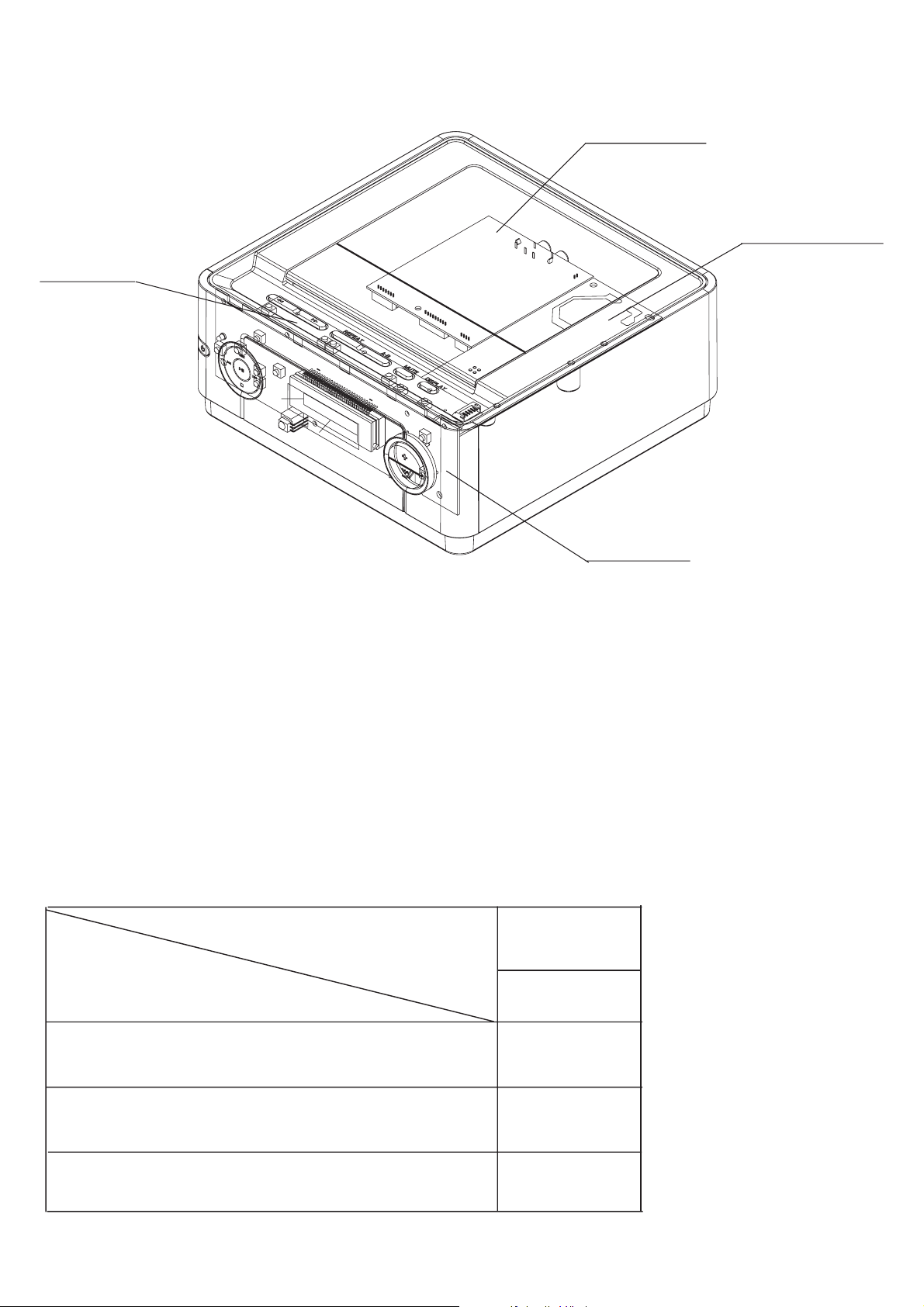
LOCATION OF PCB BOARDS
VFD PCB
1-2
MAIN PCB
POWER PCB
VERSION VARIATION:
Features & Board in used
Type / Versions:
KEY PCB
MCD106
/94
Composite video out
Voltage (Dual)
AC line cord ( xed)
X
X
X

SPECIFICATIONS
Picture
Aspect ratio .................................................................................................................. 4:3, 16:9
D/A Converter ....................................................................................................10 bit, 108 MHz]
Sound
Signal to noise ratio .......................................................................................... 90 dB, A-weight
Distortion and Noise ................................................................................................ 1 kHz 0.2%
Sound System ....................................................................................................... Dolby Digital
Convenience
Child protection ...................................................................................................... Rating Level
Power
Power supply ............................................................................................. 110-240V, 50-60 Hz
Standby power consumption ......................................................................................... < 1.5 W
Power consumption ............................................................................................................. 8 W
Cabinet
Dimensions (W x H x D) 218 x 90 x 221.5 mm
Net Weight ................................................................................................................... 1.095 kg
Packaging Dimensions (H x W x D) . ..........................................................................................
................................................................................................................... 248 x 267 x 130 mm
Gross weight .................................................................................................................... 1.5 kg
Speci cations and external appearance are subject to change without notice.
1-3
Service Tools:
Universal Torx driver holder .................................4822 395 91019
Torx bit T10 150mm ...........................................4822 395 50456
Torx driver set T6-T20 .........................................4822 395 50145
Torx driver T10 extended .....................................4822 395 50423
Compact Disc:
SBC426/426A Test disc 5 + 5A ...........................4822 397 30096
SBC442 Audio Burn-in test disc 1kHz .................4822 397 30155
SBC429 Audio Signals disc .................................4822 397 30184
Dolby Pro-logic Test Disc ....................................4822 395 10216
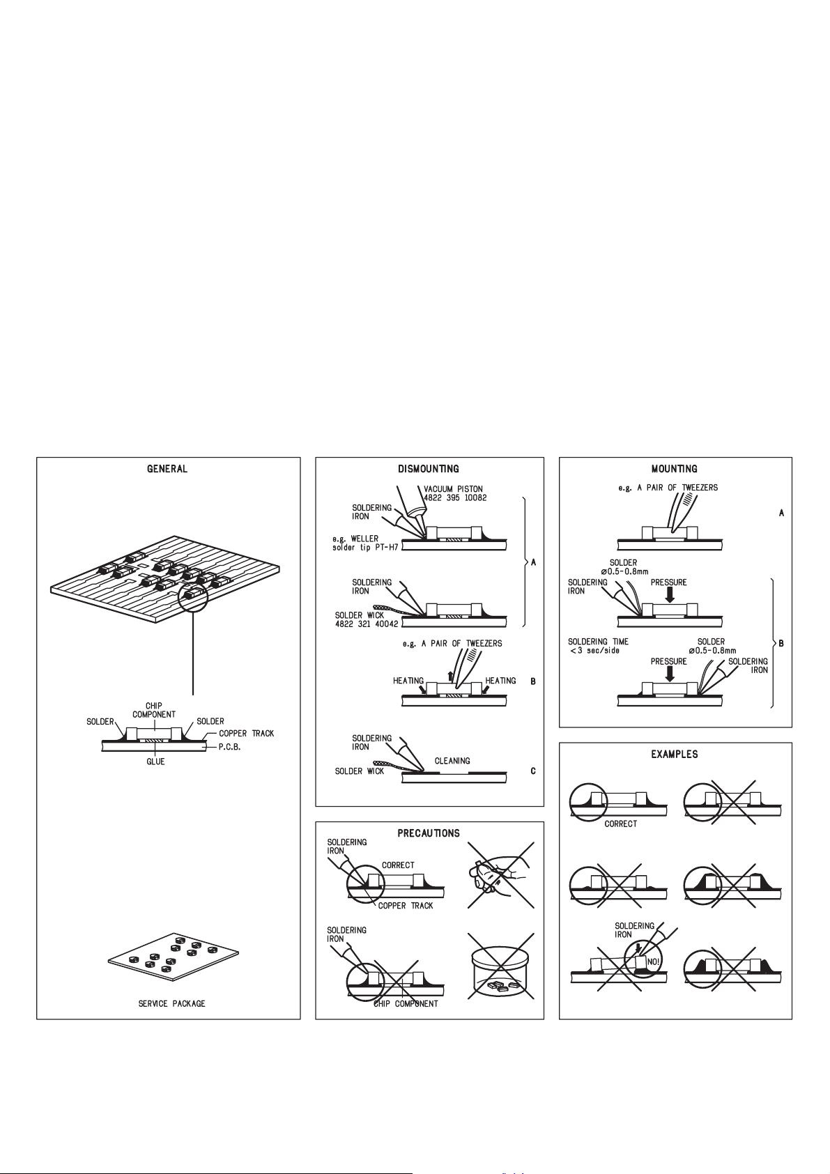
HANDLING CHIP COMPONENTS
1-4
SERVICE AIDS
1-5
Service Tools:
Universal Torx driver holder .................................4822 395 91019
Torx bit T10 150mm ...........................................4822 395 50456
Torx driver set T6-T20 .........................................4822 395 50145
Torx driver T10 extended .....................................4822 395 50423
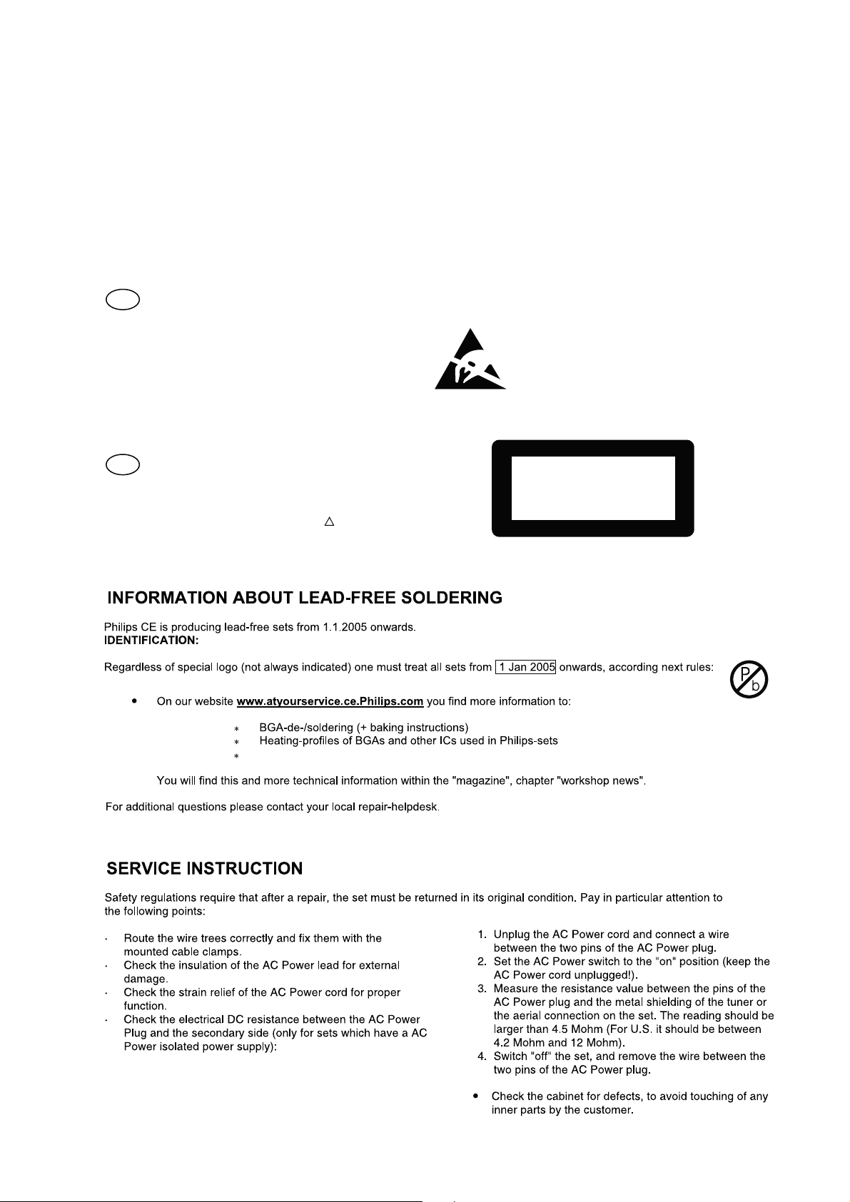
GB
All ICs and many other semi-conductors are
susceptible to electrostatic discharges (ESD).
Careless handling during repair can reduce life
drastically.
When repairing, make sure that you are
connected with the same potential as the mass
of the set via a wrist wrap with resistance.
Keep components and tools also at this
potential.
WARNING
GB
Safety regulations require that the set be restored to its original
condition and that parts which are identical with those specified,
be used
Safety components are marked by the symbol
!
.
Compact Disc:
SBC426/426A Test disc 5 + 5A ...........................4822 397 30096
SBC442 Audio Burn-in test disc 1kHz .................4822 397 30155
SBC429 Audio Signals disc .................................4822 397 30184
Dolby Pro-logic Test Disc ....................................4822 395 10216
ESD
CLASS 1
LASER PRODUCT
Lead free
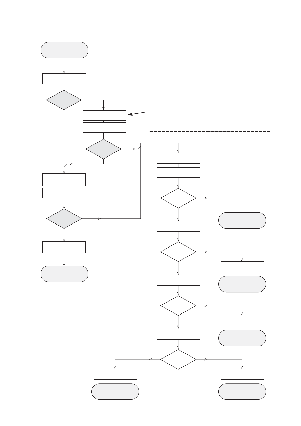
INSTRUCTIONS ON CD PLAYABILITY
Customer complaint
"CD related problem"
Set remains closed!
check playability
1
1-6
playability
ok ?
Y
Play a CD
for at least 10 minutes
check playability
playability
ok ?
Y
N
"fast" lens cleaning
check playability
playability
ok ?
N
3
For flap loaders (= access to CD drive possible)
cleaning method
4 is recommended
Standard repair procedure
N
Y
clean the lens
check playability
playability
ok ?
check "EYE-Pattern"
4
Y
N
5
return set
add Info for customer
"SET OK"
return set
1 - 7
For description - see following pages
2
replace Signal Processor
return set
EYE-Pattern
ok ?
Y
check Laser current
Laser current
ok ?
Y
check CD Drive offsets
Y
CD Drive offsets
ok ?
N
replace CD Drive
6
return set
N
replace CD Drive
7
return set
N
replace CD Drive
return set
INSTRUCTIONS ON CD PLAYABILITY
1-7
1
PLAYABILITY CHECK
For sets which are compatible with CD-RW discs
use CD-RW Printed Audio Disc ....................7104 099 96611
TR 3 (Fingerprint)
TR 8 (600µ Black dot) maximum at 01:00
• playback of these two tracks without audible disturbance
playing time for: Fingerprint ≥10seconds
Black dot from 00:50 to 01:10
• jump forward/backward (search) within a reasonable time
For all other sets
use CD-DA SBC 444A..................................4822 397 30245
TR 14 (600µ Black dot) maximum at 01:15
TR 19 (Fingerprint)
TR 10 (1000µ wedge)
• playback of all these tracks without audible disturbance
playing time for: 1000µ wedge ≥10seconds
Fingerprint ≥10seconds
Black dot from 01:05 to 01:25
• jump forward/backward (search) within a reasonable time
4
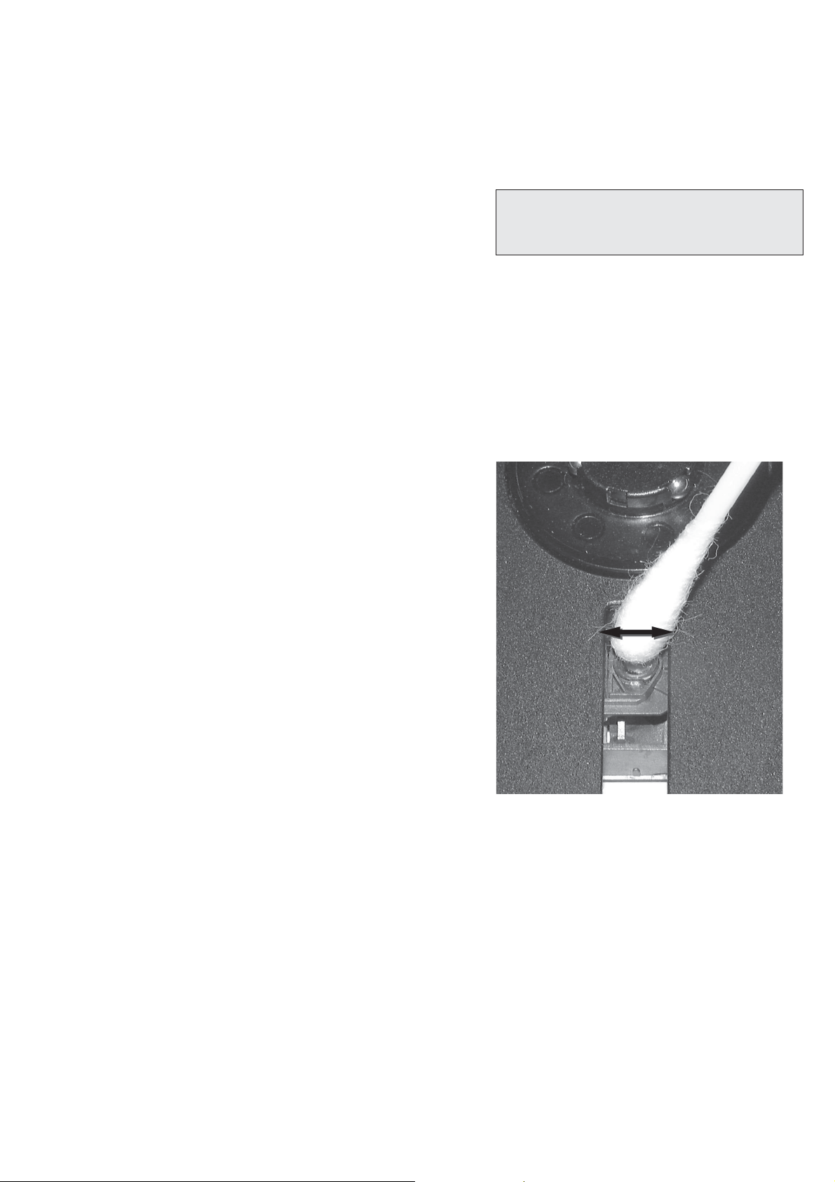
LIQUID LENS CLEANING
Before touching the lens it is advised to clean the
surface of the lens by blowing clean air over it.
This to avoid that little particles make scratches on
the lens.
Because the material of the lens is synthetic and coated
with a special anti-reflectivity layer, cleaning must be done
with a non-aggressive cleaning fluid. It is advised to use
“Cleaning Solvent B4-No2”, available with codenumber
4822 389 10026.
The actuator is a very precise mechanical component and
may not be damaged in order to guarantee its full function.
Clean the lens gently (don’t press too hard) with a soft and
clean cotton bud moistened with the special lens cleaner.
The direction of cleaning must be in the way as indicated in
the picture below.
2
CUSTOMER INFORMATION
It is proposed to add an addendum sheet to the set which
informs the customer that the set has been checked
carefully - but no fault was found.
The problem was obviously caused by a scratched, dirty or
copy-protected CD. In case problems remain, the customer
is requested to contact the workshop directly.
The lens cleaning (method 3) should be mentioned in the
addendum sheet.
The final wording in national language as well as the printing
is under responsibility of the Regional Service Organizations.
3
FAST LENS CLEANING (dry brush)
Use lens cleaning CD
SBC AC300 ...........................................9082 100 00043
Insert the lens cleaning CD, press PLAY and follow the
voice guide´s instructions on the CD.
Sanyo DA12T3
CD Drive
A
A
F
C
B
E
C
D
E
VCC
B
VREF
F
D
9
10
11
12
13
14
15
16
1800
+5V_HF
VrefCD10
A
D
E
B
C
F
GND
8
E
D
A
B
C
F
Laser power control
100n
2878
470n
2876
3821
1R
1K
3823
2880
33p
+5V
BC807-40
7879
3817
47R
3820
4R7
47R
3819
1n
2879
2877
47u
1
8
4
7811-A
LM358D
3
2
10K
3822
47R
3818
2841
100n
47n
2869
+5V_HF
LASER DIODE
U >250mV
->Laser damaged !
4,6V
3V
3,3V
3,9V
2V
0,17V
0,17V
Sanyo
DA12T3
HF-Amplifier
D3
D2
D1
680R
3905
3903
3K3
BC847B
7877
47n
2818
1K5
3902
5
7
4
2
1
6
3
64
8
9
10
11
470R
3893
+3.3V
2K2
3908
10K
3923
BC847B
7878
BC847B
7876
4n7
2813
3896
100R
220u
2885
2881
560p
47n
2887
560R
3901
2883
470n
2817
4u7
3n3
2814
3898
220R
3895
27K
470n
2884
+3.3V
3909
820R
3907
100R
3920
33K
3897
2882
82p
3K3
3904
2K7
3899
3906
470R
+5V_HF
HFIN
VrefCD10
100p
28152816
22n
LDON
to 3826,3827
VREF GE
VDDA1
VRIN
VSSA1
ISLICE
LD
ON
D1
D2
D3
D4
HFIN
HFREF
IREF
CD_DA: 0V / CD_RW: 3V
Σ (A-D)
800mVpp
TB = 0.5µs/div
EYE-PATTERN
1,8V
1,2V
2,4V
2,6V
0,65V
INSTRUCTIONS ON CD PLAYABILITY
1-8
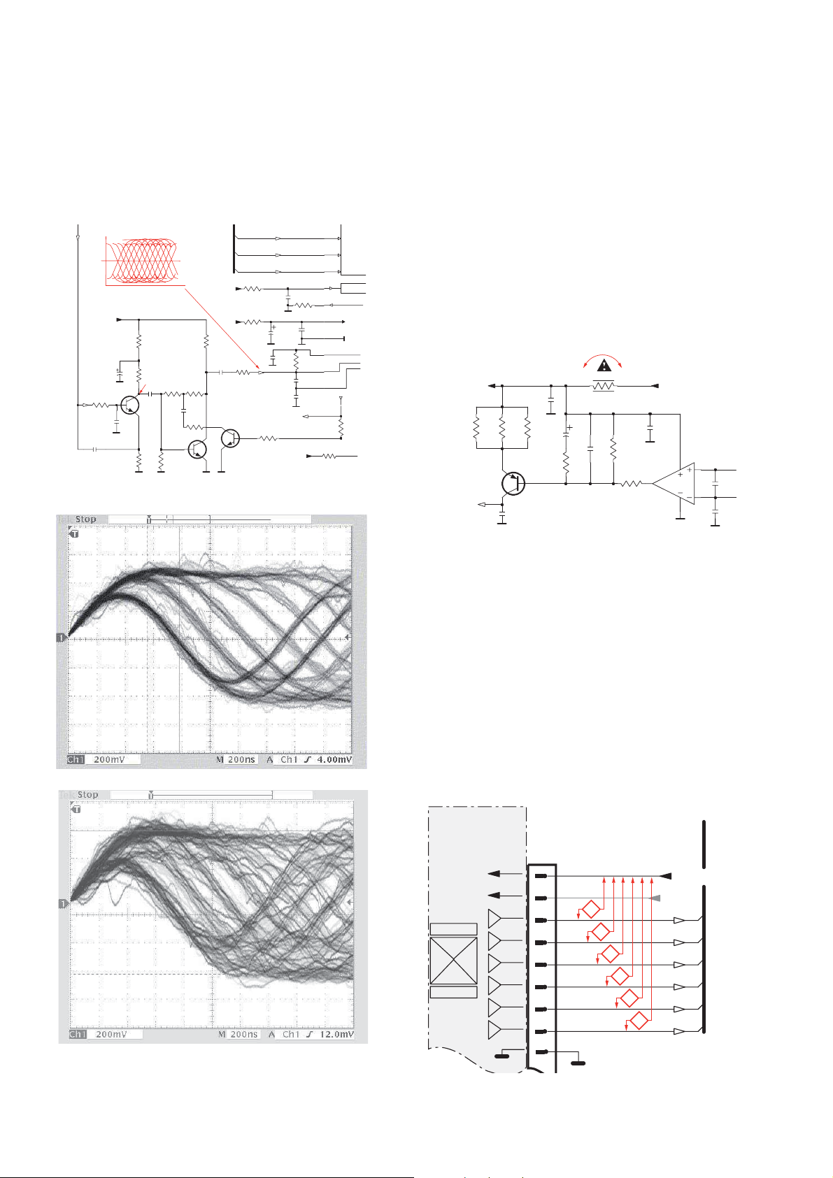
5
EYE-PATTERN SIGNAL – JITTER MEASUREMENT
Measure the signal on the input of the Signal processor
using an analog oscilloscope. Please find the exact
measuring point in your Service Manual.
See below examples of the signal. Amplitude should read at
least 700mVpp using SBC444A.
6
CD DRIVE – LASER CURRENT MEASUREMENT
The laser current can be measured as a voltage drop on a
resistor. The resistor is marked in every Service Manual.
The value depends on the type of CD drive.
typical value most probably defect
VAMxxxx : 150-230mV ≥350mV
MCDxx : 170-230mV ≥300mV
DA1x : 210-250mV ≥350mV
DA2x : 175-200mV ≥250mV
Use SBC444A (CD-DA) for measurement.
If the oscilloscope shows a signal like the ‘bad’ one, and/or
the amplitude decreases within 1 minute - the CD drive has
to be replaced.
good
bad
7
CD DRIVE – OFFSET MEASUREMENT
The photodiodes of the CD-drive may have an offset. These
offsets have to be compensated by the signal processor.
High offsets can lead to poor playability of some CDs
(skipping tracks).
To measure the offset values, start the Service Test
Program - section “Focus Test” without a CD.
The offsets can be measured with a DC Millivoltmeter
directly on the connector (see drawing below). Pin
numbering varies from drive to drive.
The values from diode A-D should read 0±10mV.
Diodes E and F are less critical.
If one of the offsets is higher than ±10mV the CD drive has
to be replaced. Otherwise replace the Signal Processor.

System , Region Code , etc. Setting Produre
2 - 12 - 1
1) System Reset
(1) System reset
a) Press “setup” button on R/C, TV will show the “setup” menu.
b) Select the menu using the q on R/C.
c) Selcet default to restore system setting.
remark: But can’t restore region code default setting.
(2) Region code reset
a) Open CD Door.
b) Press “stop” button on RC, then press “0000” TV Display
”DEFAULT”.
c) The system will switch to standby when finished,and region code
will to be default setting.
2) Region Code Change
a) Press “5168” on R/C in open mode.
b) Use "q” “p” on R/C to selece desirde region code in custorner
page.
c) Pess “OK” to confirn:
1 USA
2 EU
3 AP
4 Australia, NZ, Latam
5 Russia,INDIA
6 CHINA
5) Upgrading new sofeware
a) Open the CD door,then insert the CD-R program disc.
b) Close the CD door.
c) TV will show the upgrade prompt menu, and the system will auto
upgrading, the system will switch to standby when nish upgrading.
* the latest upgraded is in version VER 070602.
CAUTION !
This information is con dencial and may not be
distributed. Only a quali ed service person should
reprogram the Region Code.
3) Password Change
a) Press “setup“ button on R/C,TV shows the “setup“ menu.
b) Press "u” to select “password”, then press “u/OK”.
* 0000 is default password supplied.
4) Check on the Sofeware Version
a) Open the CD door.
b) Press “stop 159” button on R/C.
c) TV will show the version on screen.
REPAIR INSTRUSTRATOR
2 - 22 - 2
 Loading...