

Page 1

IntelliVue MX40
Installation and Service
Page 2

Notice
Proprietary Information
This document contains proprietary information, which is protected by
copyright.
Copyright
Copyright © 2011 Koninklijke Philips Electronics N.V. All rights reserved.
Reproduction in whole or in part is prohibited without the prior written
consent of the copyright holder. Philips Medical Systems Nederland B.V.
reserves the right to make changes in specifications and/or to discontinue any
products at any time without notice or obligation and will not be liable for any
consequences resulting from the use of this publication.
OxiCliq ® and OxiMax ® are registered trademarks of Nellcor Incorporated.
Duracell ® is a registered trademark of Procter & Gamble Incorporated.
STERRAD ® is a registered trademark of Advanced Sterilization Products.
GORE-TEX ® is a registered trademark of W.L. Gore & Assoc. Incorporated
Tone modulation is licensed under US patent 4,653,498 from Nellcor Puritan
Bennett Incorporated.
Manufacturer
Philips Medical Systems
3000 Minuteman Road
Andover, MA 01810-1099
(978) 687-1501
Printed in USA
Document number
4535 642 81301
Warranty
The information contained in this document is subject to change without
notice. Philips Medical Systems makes no warranty of any kind with regard to
this material, including, but not limited to, the implied warranties or
merchantability and fitness for a particular purpose. Philips Medical Systems
shall not be liable for errors contained herein or for incidental or consequential
damages in connection with the furnishing, performance, or use of this
material.
ii
Page 3

FCC
This device complies with Part 15 and/or Part 95 of the FCC Rules. Operation
is subject to the following two conditions: (1) these devices may not cause
harmful interference, and (2) these devices must accept any interference
received, including interference that may cause undesired operation.
Changes and modifications not expressly approved by Philips Medical
Systems can void your authority to operate this equipment under Federal
Communications Commission's rules
Printing History
New editions of this document will incorporate all material updated since the
previous edition. Update packages may be issued between editions and
contain replacement and additional pages to be merged by a revision date at
the bottom of the page. Note that pages which are rearranged due to changes
on a previous page are not considered revised.
The documentation printing date and part number indicate its current edition.
The printing date changes when a new edition is printed. (Minor corrections
and updates which are incorporated at reprint do not cause the date to
change.) The document part number changes when extensive technical
changes are incorporated.
First Edition June 2011
Document Conventions
In this guide:
Warnings
Warning
A Warning alerts you to a potential serious outcome, adverse event or safety
hazard. Failure to observe a warning may result in death or serious injury to
the user or patient.
iii
Page 4

Cautions
Caution
A Caution alerts you to where special care is necessary for the safe and
effective use of the product. Failure to observe a caution may result in minor
or moderate personal injury or damage to the product or other property, and
possibly in a remote risk of more serious injury.
Notes
A Note contains additional information on the product's usage.
iv
Page 5

Contents
1. Introduction 1-1
2. Installation 2-1
MX40 Compatibility -------------------------------------------------------------------- 2-2
Label Assignment for MX40 --------------------------------------------------------- 2-3
Equipment Label Character Limitations ------------------------------------------ 2-4
Assigning an Equipment Label ----------------------------------------------------- 2-5
Frequency Management and Channel Selection ------------------------------ 2-6
1.4GHz Smart-hopping Channel Definition --------------------------------- 2-8
Short-Range Radio Channel Selection for 1.4GHz Smart-hopping
Systems ---------------------------------------------------------------------------------- 2-10
Channel Comparison - Short-Range Radio and 802.11b,g Channels2-11
SRR Channel Selection for 1.4GHz Installations ------------------------- 2-11
Smart-hopping and SRR Channel Selection for 2.4GHz
Smart-hopping Systems -------------------------------------------------------- 2-12
Channel Comparison - Short-Range Radio and 802.11b -------------- 2-13
802.11 Channel 1,6,11 Deployment ----------------------------------------- 2-14
802.11 Channel 1,4,7,11 Deployment --------------------------------------- 2-15
802.11 Channel 1,4,8,11 Deployment --------------------------------------- 2-15
802.11 Channel 1,7,13 Deployment ----------------------------------------- 2-16
802.11 Channel 1,5,9,13 Deployment --------------------------------------- 2-17
802.11 Channel 2,7,12 Deployment ----------------------------------------- 2-18
802.11 Channel 1,6,11,14 Deployment ------------------------------------- 2-19
802.11 Channel 3,10,14 Deployment --------------------------------------- 2-19
Short-Range Radio Density ---------------------------------------------------- 2-20
3. Test and Inspection 3-1
MX40 Test & Inspection Matrix ----------------------------------------------------- 3-2
4. Operating Modes 4-1
Monitoring Mode ------------------------------------------------------------------------ 4-2
Controls, Indicators and Connectors ----------------------------------------- 4-2
Operating and Navigating ------------------------------------------------------- 4-7
Understanding Settings --------------------------------------------------------- 4-10
Battery Information --------------------------------------------------------------- 4-12
Inserting Batteries ---------------------------------------------------------------- 4-15
Removing the Batteries --------------------------------------------------------- 4-17
Service Information Availabe in Monitoring Mode ------------------------ 4-20
Configuration Mode ------------------------------------------------------------------- 4-22
Clinical Configuration ------------------------------------------------------------ 4-22
Service Mode --------------------------------------------------------------------------- 4-24
Setup Network --------------------------------------------------------------------- 4-24
Revisions ---------------------------------------------------------------------------- 4-24
Contents - 1
Page 6

Demo Mode ---------------------------------------------------------------------------- 4-25
5. Maintenance 5-1
Cleaning ----------------------------------------------------------------------------------- 5-2
Cleaning Materials for the MX40 ----------------------------------------------- 5-2
Disposing of the MX40 ---------------------------------------------------------------- 5-4
Label Assignment for Replacement MX40 --------------------------------------- 5-5
Re-assigning an Equipment Label -------------------------------------------- 5-5
Charging Lithium-ion Rechargeable Batteries ---------------------------------- 5-7
Battery Power Indicators --------------------------------------------------------- 5-7
Battery Lifetime Management -------------------------------------------------- 5-8
Battery Disposal -------------------------------------------------------------------- 5-9
6. Part and Option Ordering Information 6-1
MX40 Product Structure -------------------------------------------------------------- 6-2
MX40 Support Parts ------------------------------------------------------------------- 6-5
7. MX40 Repair Strategy 7-1
Tools Required -------------------------------------------------------------------------- 7-2
Software License Transfer ----------------------------------------------------------- 7-3
8. Troubleshooting 8-1
Technical Alarms (INOPs) ----------------------------------------------------------- 8-2
Possible User Interface Issues ---------------------------------------------------- 8-10
9. Safety Standards & Specifications 9-1
Regulatory Information ---------------------------------------------------------------- 9-2
Software Hazard Prevention ---------------------------------------------------- 9-2
AC Power Source ------------------------------------------------------------------ 9-2
Industrie Canada Compliance (Canada) ------------------------------------- 9-2
Safety Standards ------------------------------------------------------------------- 9-2
Intended Use Statement --------------------------------------------------------- 9-3
Indications for Use ----------------------------------------------------------------- 9-3
Intended Uses of MX40 ---------------------------------------------------------- 9-4
Authorized EU Representative ------------------------------------------------- 9-4
Patient Population ----------------------------------------------------------------- 9-4
Rx -------------------------------------------------------------------------------------- 9-4
Essential Performance ----------------------------------------------------------- 9-5
Electromagnetic Compatibility ------------------------------------------------------- 9-6
Reducing Electromagnetic Interference -------------------------------------- 9-7
Restrictions for Use---------------------------------------------------------------- 9-7
Electromagnetic Compatibility (EMC) Specifications --------------------- 9-7
Electromagnetic Emissions ------------------------------------------------------ 9-8
Electromagnetic Immunity ------------------------------------------------------- 9-9
Recommended Separation Distance ----------------------------------------- 9-9
Battery Specifications --------------------------------------------------------------- 9-12
Lithium-ion Battery Charge Time ------------------------------------------------- 9-15
Contents - 2
Page 7

Physical Specifications--------------------------------------------------------------- 9-16
MX40 1.4 GHz Radio ----------------------------------------------------------------- 9-17
MX40 2.4 GHz Radio ----------------------------------------------------------------- 9-18
MX40 Short-Range Radio ----------------------------------------------------------- 9-20
Environmental Specifications ------------------------------------------------------ 9-21
Measurement Specifications ------------------------------------------------------- 9-22
ECG ---------------------------------------------------------------------------------- 9-22
ECG Performance Disclosure/Specifications------------------------------ 9-23
FAST SpO2 ------------------------------------------------------------------------- 9-25
SpO2 Sensor Accuracy ---------------------------------------------------------- 9-27
Contents - 3
Page 8

Contents - 4
Page 9
1. Introduction
The MX40 is compatible with the Philips Smart-hopping wireless network
which is designed for use in ambulatory care areas of hospitals,
rehabilitation facilities, and cardiac care centers.
The Smart-hopping wireless network provides ambulatory and bedside
monitoring of ECG, SpO2 and NBP. The network encompasses a number of
individual units which connect to form a complete method of transporting
patient data to a central repository for subsequent distribution to clinical
staff.
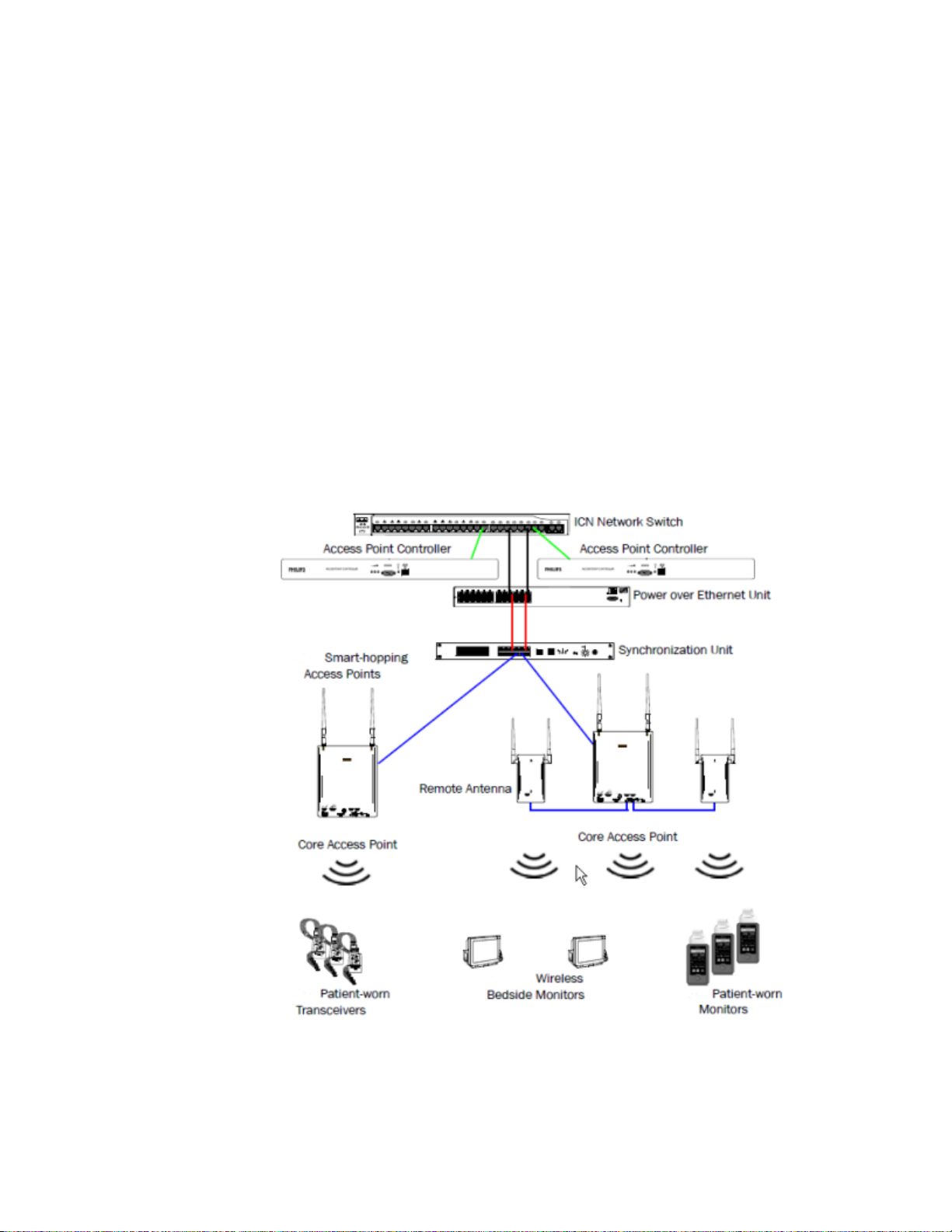
The Smart-hopping wireless network is comprised of the following devices
and components:
Introduction 1-1
Page 10

1-2 Introduction
Page 11

MX40 Compatibility .................................................................................. 2-2
Label Assignment for MX40 .................................................................... 2-3
Equipment Label Character Limitations ................................................ 2-4
Assigning an Equipment Label ............................................................... 2-5
Frequency Management and Channel Selection ................................... 2-6
Short-Range Radio Channel Selection for 1.4GHz Smart-hopping
Systems ..................................................................................................... 2-10
2. Installation
This section provides compatibility and configuration information for
reference during MX40 installation.
Installation 2-1
Page 12

MX40 Compatibility
The MX40 is compatible for use with IntelliVue Information Center Release
N. Limited compatibility is offered when used with IntelliVue Information
Center Release L or M. See the "Operating with Release L or M" chapter for
more information.
The MX40 is compatible for use with IntelliVue Patient Monitors Release G
or later when wirelessly connected.
The MX40 is compatible for use with IntelliVue Cableless Measurements
Release A.1.
The MX40 is compatible for use with Access Point Controller 862147,
Release B.00.19 and Access Point Controller 865346, Release C.00.XX.
The MX40 Patient Cable is compatible for use with IntelliVue Patient
Monitor platforms MP2/X2, MP5/MP5T/MP5SC, MP20/30 with MMS or X2,
MP40/50 with MMS or X2, MP60/70 with MMS or X2, MP80/90 with MMS
or X2, and MX800/700/600 with MMS or X2.
2-2 Installation
Page 13

Label Assignment for MX40
When the MX40 is shipped from the factory, it is shipped with an
Equipment Label of "NEW_DEVICE" and an RF Access Code of "0". This
allows connection to any Smart-hopping Access Point.
After the MX40 has connected to the wireless network, the device gets the
RF Access Code and Equipment Label configuration through the "Label
Assignment" function at the Information Center. The Label Assignment
function is password protected. The password is "tele".
Installation 2-3
Page 14
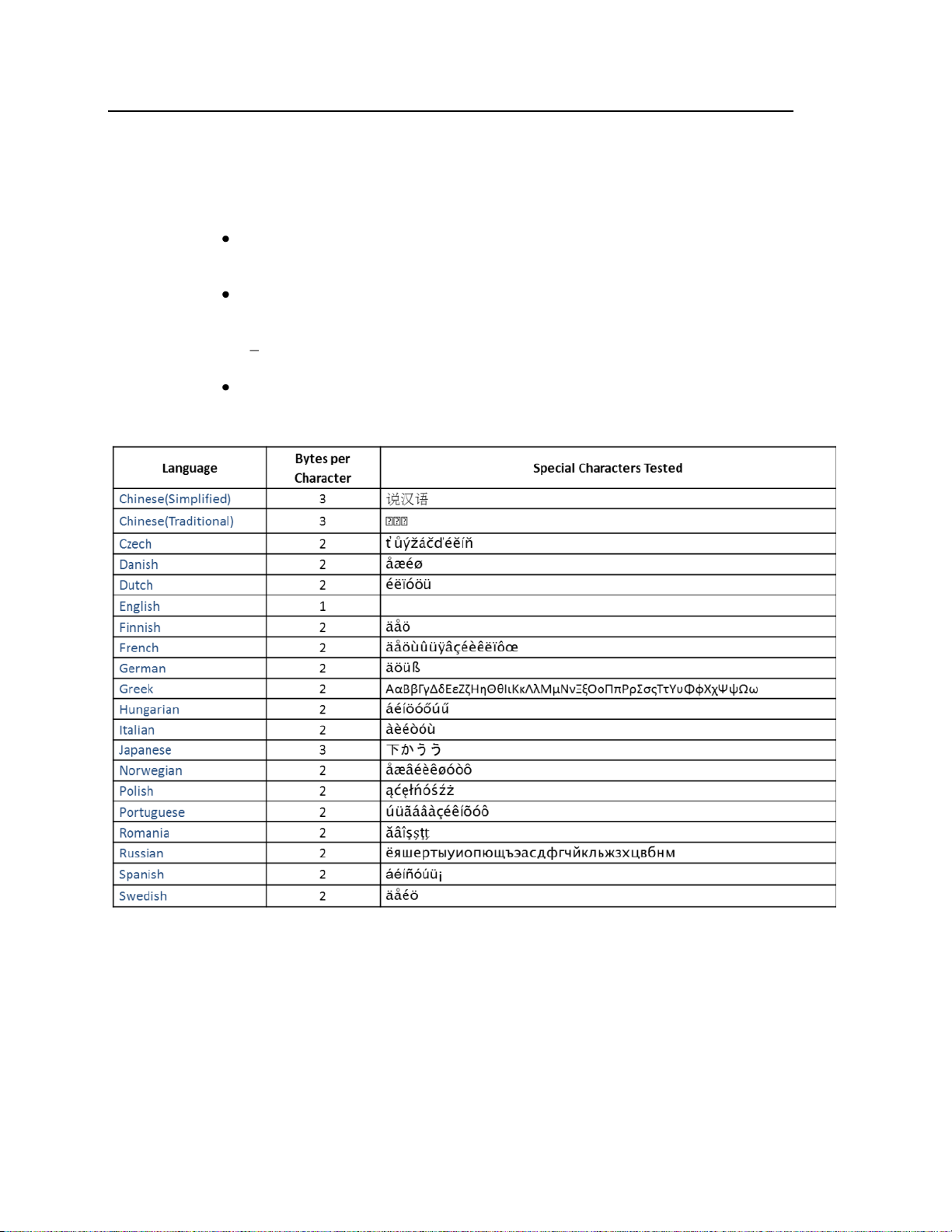
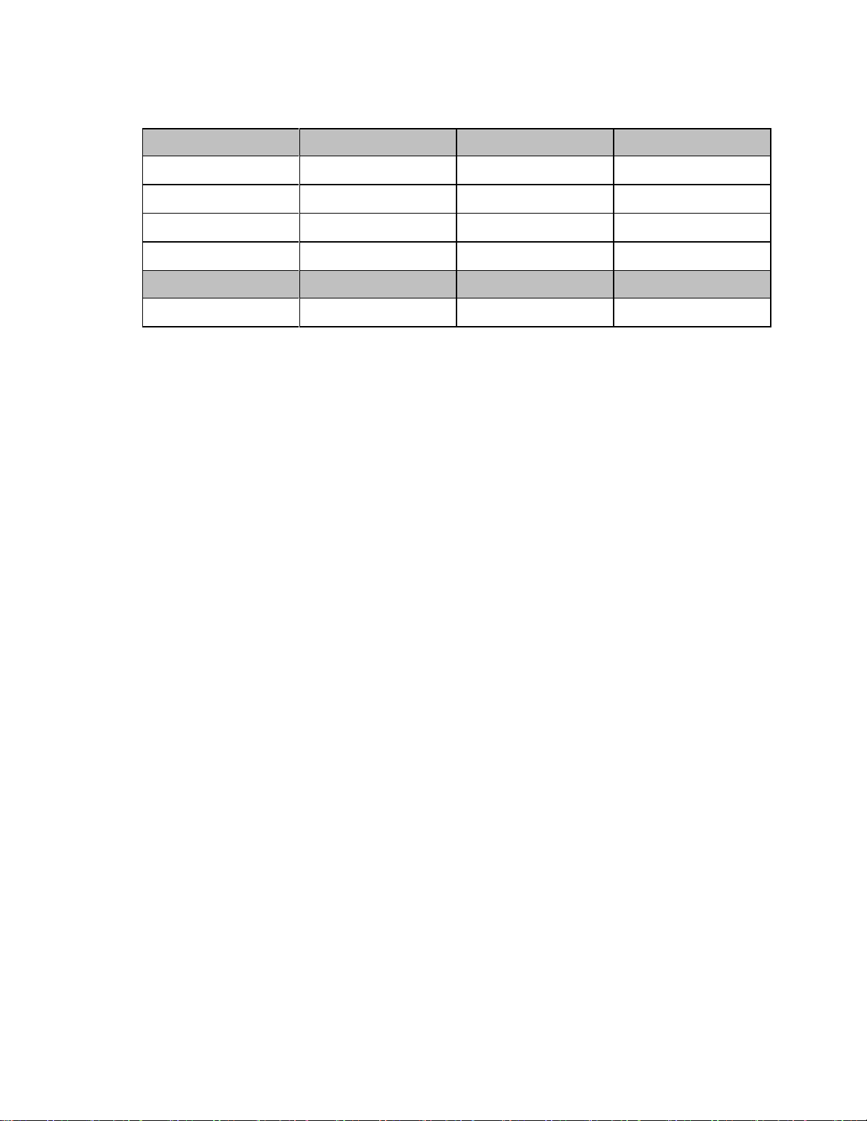
Equipment Label Character Limitations
Equipment labels are limited to a maximum of 10 bytes. If the equipment
label exceeds the 10 byte maximum, the label assignment process will fail.
UTF-8 encoded characters may use 1-4 bytes depending on the
language. (http://en.wikipedia.org/wiki/UTF-8)
The first 128 Unicode characters (which corresponds directly to the
ASCII character set) take only 1 byte.
Example: Tele1 (English) is 5 bytes long.
If you use special characters, more bytes are required.
Refer to the table below for character limit information:
2-4 Installation
Page 15
Assigning an Equipment Label
To assign an equipment label to a device:
1 Select All Controls -> Label Assignment.
2 Enter password (tele)
3 Insert battery power into the MX40 and if attached, disconnect the
patient cable.
4 Select Refresh.
5 Confirm the connection to the wireless network as follows:
6 Select the MAC address of the replacement device from the New
Devices list. If the address does not appear, remove battery power and
re-insert. Select Refresh.
Note — The MAC address appears on the rear label of the MX40.
7 Select the desired equipment label from the Equipment Label list.
8 Select Assign Label to initiate programming of the equipment label
and RF Access Code into the MX40.
9 When prompted, press Confirm on the MX40 to accept the assignment.
The confirmation must occur within 30 seconds of the prompt.
10 On the MX40, wait for the New_Device label to change to the selected
equipment label.
11 Confirm the label assignment by viewing the waveform in the Patient
Sector at the Information Center.
Installation 2-5
Page 16

Frequency Management and Channel Selection
Management of the RF environment in a facility is important to the overall
performance of any wireless system. Philips Medical Systems cannot
control what wireless devices are used in a healthcare facility, but we will
work with you to select the best frequencies to use in order to avoid
interference with other wireless devices used within the hospital.
Frequency Management
Frequency management is the selection of frequencies for wireless devices
within a facility to prevent interference between devices.
Frequency Management Responsibility
Frequency management is the responsibility of the hospital. Philips
Medical Systems has no control over the RF environment in a hospital. If
interference exists at the operating frequencies, system performance will be
affected. Careful selection of frequencies for all wireless devices used
within a facility is important to prevent interference between them.
Channel Selection
The MX40 has two radios – the Smart-hopping radio and the Short Range
Radio (optional). Channel selection for the two radios is different for a 1.4
GHz Smart-hopping system versus a 2.4 GHz Smart-hopping system.
Therefore they will be discussed separately.
Channel Selection for 1.4 GHz Smart-hopping Systems
The 1.4 GHz MX40 operates in the FCC-allocated, protected Wireless
Medical Telemetry Service (WMTS) in the 1395-1400 and 1427-1432 MHz
bands. Operation of this equipment requires the prior coordination with a
frequency coordinator designated by the FCC for the Wireless Medical
Telemetry Service.
The Smart-hopping channels that can be used will be determined by this
coordination process. A minimum of three Smart-hopping channels is
required for proper operation of the system, but using more channels will
improve performance. Smart-hopping channels are configured in the
Access Point Controller.
Frequency Coordination (WMTS only)
2-6 Installation
Operation of this equipment requires the prior coordination with a
frequency coordinator designated by the FCC for the Wireless Medical
Telemetry Service.
Page 17

Frequency coordination is a registration and coordination process for
wireless medical telemetry devices used in the U.S.A. which operate in the
FCC-allocated, protected Wireless Medical Telemetry Service (WMTS)
bands (608-614 MHz, 1395-1400 MHz, 1427-1432 MHz). The MX40
operates in the 1395-1400 and 1427-1432 MHz bands.
Under U.S. Federal Communications Commission (FCC) rules, authorized
healthcare providers must register their WMTS devices with an authorized
Frequency Coordinator designated by the FCC. The American Society for
Healthcare Engineering (ASHE) is the current designated Frequency
Coordinator.
Registration/Coordination is a two-step process.
Step 1: Registration: The healthcare facility must register with ASHE. This
is done on-line, from the ASHE website (www.ashe.org - search on
keyword "WMTS"). Click on the link for Wireless Medical Telemetry
Service and you will come to the registration page. Fill out the details, and
pay the associated fee as per the instructions provided. You will receive
confirmation of this registration. Confirmation must be received before
proceeding to the next step.
Step 2: Frequency Coordination: Along with confirmation of
registration, you will receive access information necessary to perform the
second step, frequency coordination. This step involves logging the
equipment and frequencies used into the FCC’s database, so as to identify
any existing potential interference and to help prevent potential future
interference. Like registration, coordination is accomplished via the
ASHE website. Click on the links for Wireless Medical Telemetry Service
and then Frequency Coordination. The way the coordination process is
executed as of today, it will need to be repeated twice for the ITS4840A
system; once for 1395-1400 MHz band, and then again for the 1427-1432
MHz band, both of which are used concurrently by the Philips product.
There is a separate fee for each coordination request. Coordination is
executed by a company named Comsearch, on behalf of ASHE.
To fill in the frequency coordination forms, you’ll need to know the
following:
The county.
Latitude and longitude that represents the center of the area where the
transmitting devices will be deployed. Comsearch can help provide
this information; www.comsearch.com provides contact information.
The name/s of the Clinical Unit/s using the devices (e.g. ICU4,
CCU-West, ER1, Step-Down North, etc)
Installation 2-7
Page 18
Primary
Low
Center
High
Channel 1:
1395.0977MHz
1395.8977MHz
1396.6977MHz
Channel 2:
1396.6970MHz
1397.4970MHz
1398.2970MHz
Channel 3:
1398.2963MHz
1399.0963MHz
1399.8963MHz
Channel 4:
1427.0979MHz
1427.8979MHz
1428.6979MHz
Secondary
Low
Center
High
*Channel 5:
1428.6972MHz
1429.4972MHz
1430.2972MHz
*Channel 6:
1430.2965MHz
1431.0965MHz
1431.8965MHz
The radius of deployment, expressed in meters. Imagine drawing a
circle around the center of the clinical unit, that encloses/encompasses
the unit. What is its radius?
The number of the highest floor on which a transmitting device will
operate.
How many transmitting devices will be used, i.e. the total number of
MX40 devices, Access Points, Core Access Points, and Remote Antennas
combined.
The Effective Radiating Power: 6.3 mW.
The Equipment Manufacturer: Philips Medical Systems.
The Equipment Models: MX40, etc.
The Frequency Range to be used: Two separate coordinations are
required: For the first one, click on the range of 1395.0 through 1400.0
MHz. For the second one, click on all the frequency ranges listed in the
range of 1427.0 through 1432.0 MHz.
When both Registration and Frequency Coordination have been
successfully completed, the MX40 can be activated. Note that this process
is the responsibility of the customer, as the final “operator” of the
transmitting equipment.
1.4GHz Smart-hopping Channel Definition
1.4GHz Smart-hopping Channel Definition - Standard
2-8 Installation
Page 19
Primary
Low
Center
High
Channel 1:
1395.0977MHz
1395.8977MHz
1396.6977MHz
Channel 2:
1396.6970MHz
1397.4970MHz
1398.2970MHz
Channel 3:
1398.2963MHz
1399.0963MHz
1399.8963MHz
Channel 4a:
1429.4410MHz
1430.2410MHz
1431.0410MHz
Secondary
Low
Center
High
*Channel 4:
1427.0979MHz
1427.8979MHz
1428.6979MHz
1.4GHz Smart-hopping Channel Definition - Carved-out Areas
Installation 2-9
Page 20

Short-Range Radio Channel Selection for 1.4GHz
Smart-hopping Systems
When the MX40 is to be connected to an IntelliVue Cableless Measurement
device, the Short-range radio channel assignment is handled at the MX40.
When the MX40 is to be connected to an IntelliVue Patient Monitor, the
Short-range radio channel assignment is handled at the patient monitor.
The Short Range Radio operates in the 2.4 GHz band, and is therefore
subject to interference from other devices that operate in this band like
802.11b, g wireless LANs, microwave ovens, Bluetooth radios, etc.. The
most likely interference will come from 802.11b, g wireless LANs.
In order to avoid interference, the Short Range Radio channels should be
chosen to operate at different frequencies as illustrated in the diagram
below, and as captured in the table below.
For example, if the hospital has an 802.11 deployment using 802.11 channels
1, 6, and 11, Short Range Radio channels that operate at frequencies in
between and above these channels would be SRR channel 15 (between
802.11 channels 1 and 6), SRR channel 20 (between 802.11 channels 6 and
11) and SRR channels 25 and 26 (above 802.11 channel 11).
The table also lists some Short Range Radio channels that may be used if a
frequency survey is performed and a power level check is done to ensure
that the frequency is "clear" (has a power level < -80dBm).
2-10 Installation
Page 21
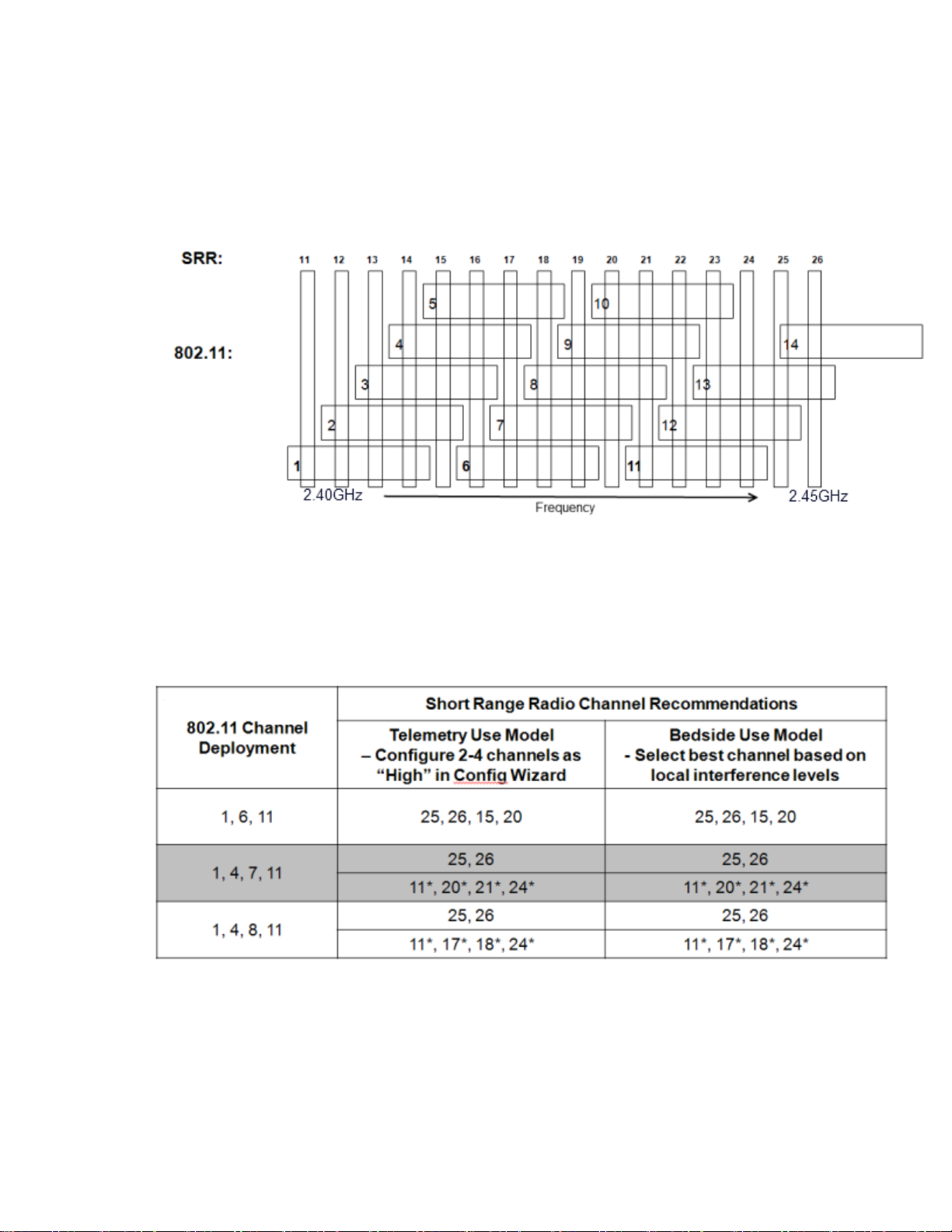
Channel Comparison - Short-Range Radio and 802.11b,g
Channels
The diagram below is for use in 1.4GHz Smart-hopping installations when
trying to select the best available Short-range radio channels.
Note — Channel overlap as shown in this diagram is not totally accurate.
There is not sufficient resolution to pick channels solely by using this
diagram. Use it in conjunction with the tables provided.
SRR Channel Selection for 1.4GHz Installations
*Requires RF Frequency Survey and RF Power Level Check for clear channels. Clear SRR channels have a power level < -80dBm.
Installation 2-11
Page 22

Smart-hopping and SRR Channel Selection for 2.4GHz
Smart-hopping Systems
For 2.4 GHz Smart-hopping systems, both the Smart-hopping radio and the
Short-Range Radio operate in the 2.4 GHz band, and therefore are subject to
interference from other devices that operate in this band like 802.11b, g
wireless LANs, microwave ovens, Bluetooth radios, etc.. The most likely
interference will come from 802.11b, g wireless LANs. In addition, if the
Short Range Radio will be used, interference between the Smart-hopping
radio and Short-Range Radio must be avoided by separating these channels
by a minimum of 5 MHz.
In order to avoid interference, the Smart-hopping and Short-Range Radio
channels should be chosen to operate at different frequencies as captured in
the tables that follow.
A minimum of three Smart-hopping channels is required for operation of
the system, but we strongly recommend selecting the maximum of six
channels in order to improve performance.
For example, if a 2.4GHz Smart-hopping system is being deployed without
the Short Range Radio in a hospital with an 802.11 deployment of channels
1, 6 and 11, the best channels to use would be the channels listed as
"Primary" in the table, "802.11 Channel 1,611 Deployment", – 13, 14, 28, 42,
43, 44, 45, 46, 47. The best six of these Smart-hopping channels across the
whole coverage area should be selected. A clear Smart-hopping channel is
defined as having a power level of < -90dBm.
If a 2.4GHz Smart-hopping system is being deployed with the Short-Range
Radio in a hospital with an 802.11 deployment of channels 1, 6 and 11, a
number of different deployment options are given in the tables. The clearest
frequencies should be assigned to the Short Range Radio, and then the
Smart-hopping channels can be assigned. So if SRR channels 25 and 26 are
selected, then the best Smart-hopping channels to use would be the
channels listed as "Primary" in the table, "802.11 Channel 1,611
Deployment", – 13, 14, 28, (42, 43, 44, 45, 46, 47 should not be used because
they will interfere with the Short Range Radio). In addition to these three
Smart-hopping channels, best three channels of the "Secondary" (0, 29) and
"Tertiary" (12, 15, 27) channels listed should be selected.
2-12 Installation
Page 23
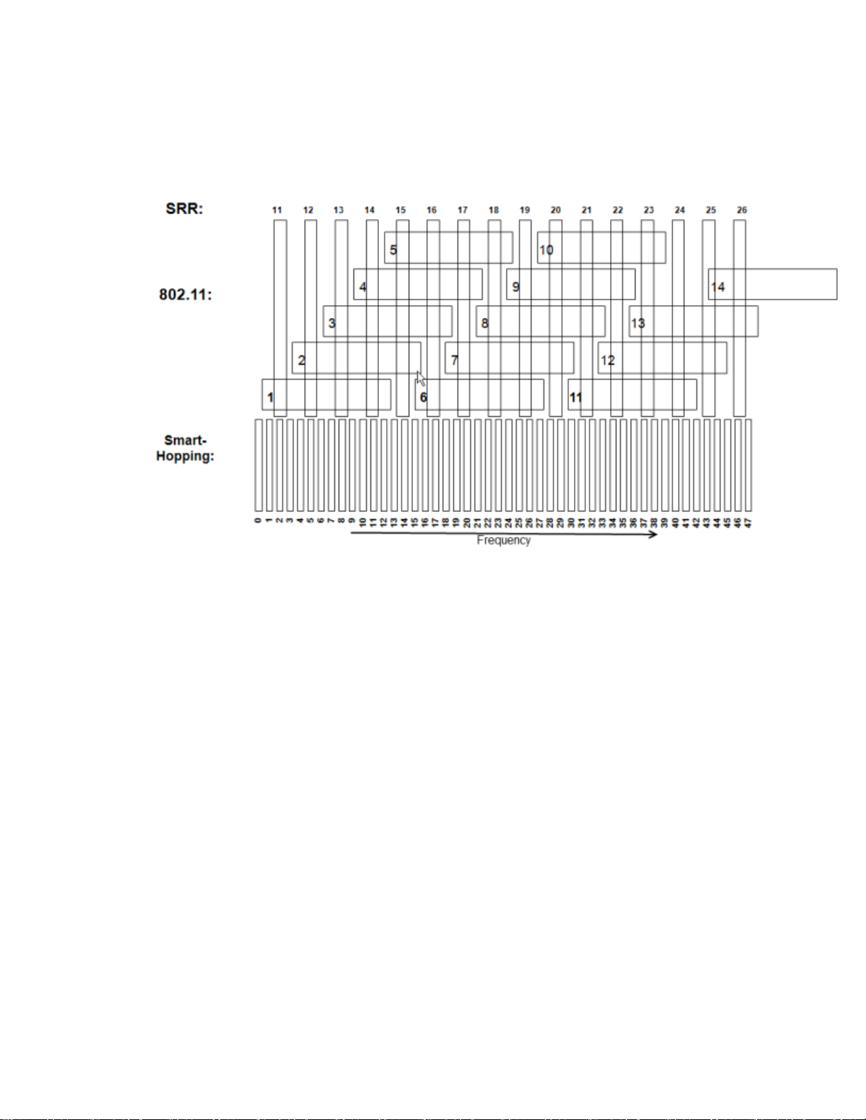
Channel Comparison - Short-Range Radio and 802.11b
The diagram below is for use in 2.4GHz Smart-hopping installations when
trying to select the best available Short-range radio channels.
Note — Channel overlap as shown in this diagram is not totally accurate.
There is not sufficient screen resolution to pick channels solely by using this
diagram. Use it in conjunction with the tables provided.
Installation 2-13
Page 24
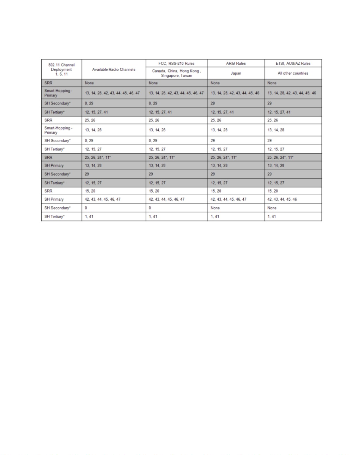
802.11 Channel 1,6,11 Deployment
*Requires RF Frequency Survey and RF Power Level Check for clear channels. Clear SRR channels have a power level < -80dB. Clear Smart-hopping
channels have a power level < -90dBm.
2-14 Installation
Page 25
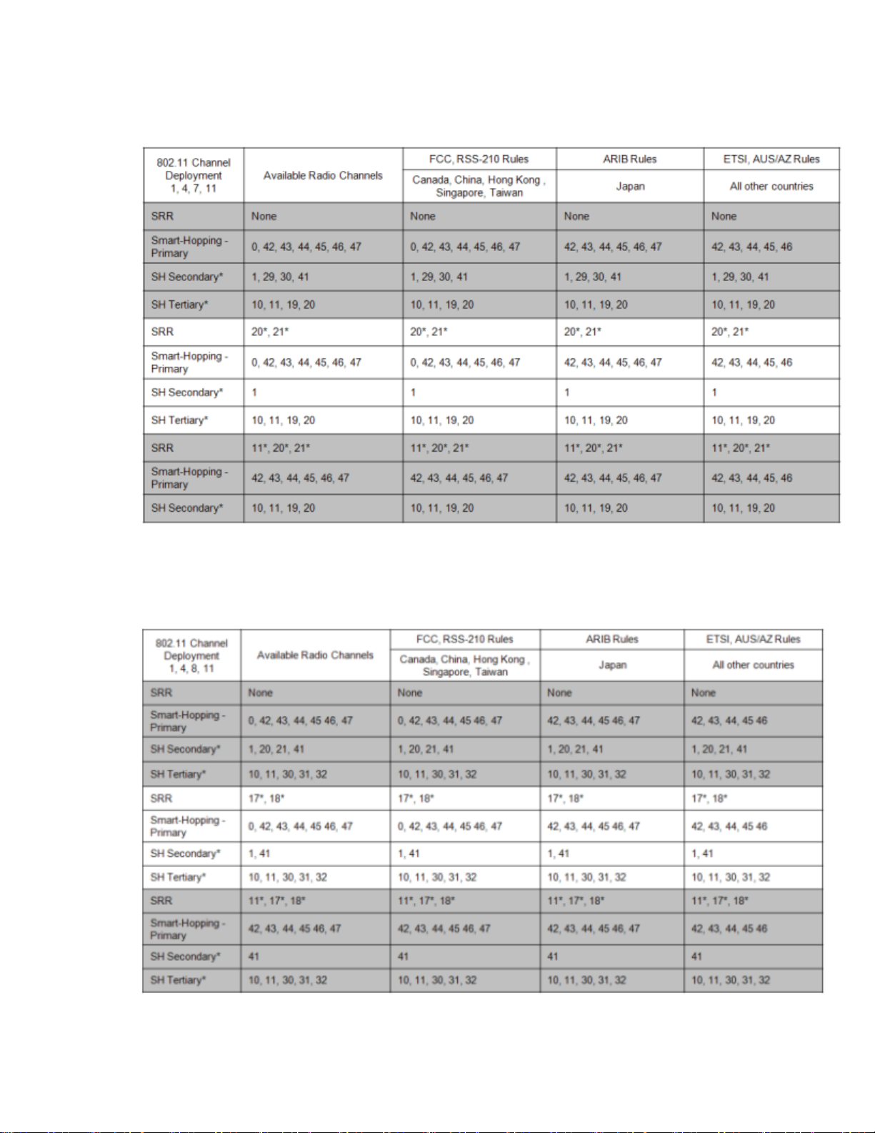
802.11 Channel 1,4,7,11 Deployment
*Requires RF Frequency Survey and RF Power Level Check for clear channels. Clear SRR channels have a power level < -80dB. Clear Smart-hopping
channels have a power level < -90dBm.
802.11 Channel 1,4,8,11 Deployment
*Requires RF Frequency Survey and RF Power Level Check for clear channels. Clear SRR channels have a power level < -80dB. Clear Smart-hopping
channels have a power level < -90dBm.
Installation 2-15
Page 26
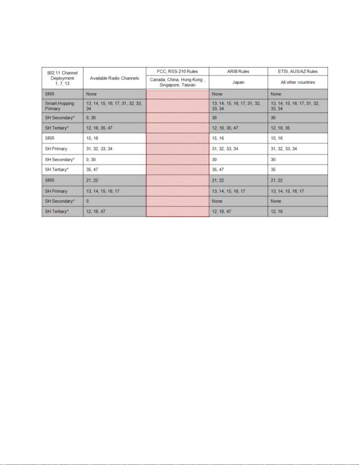
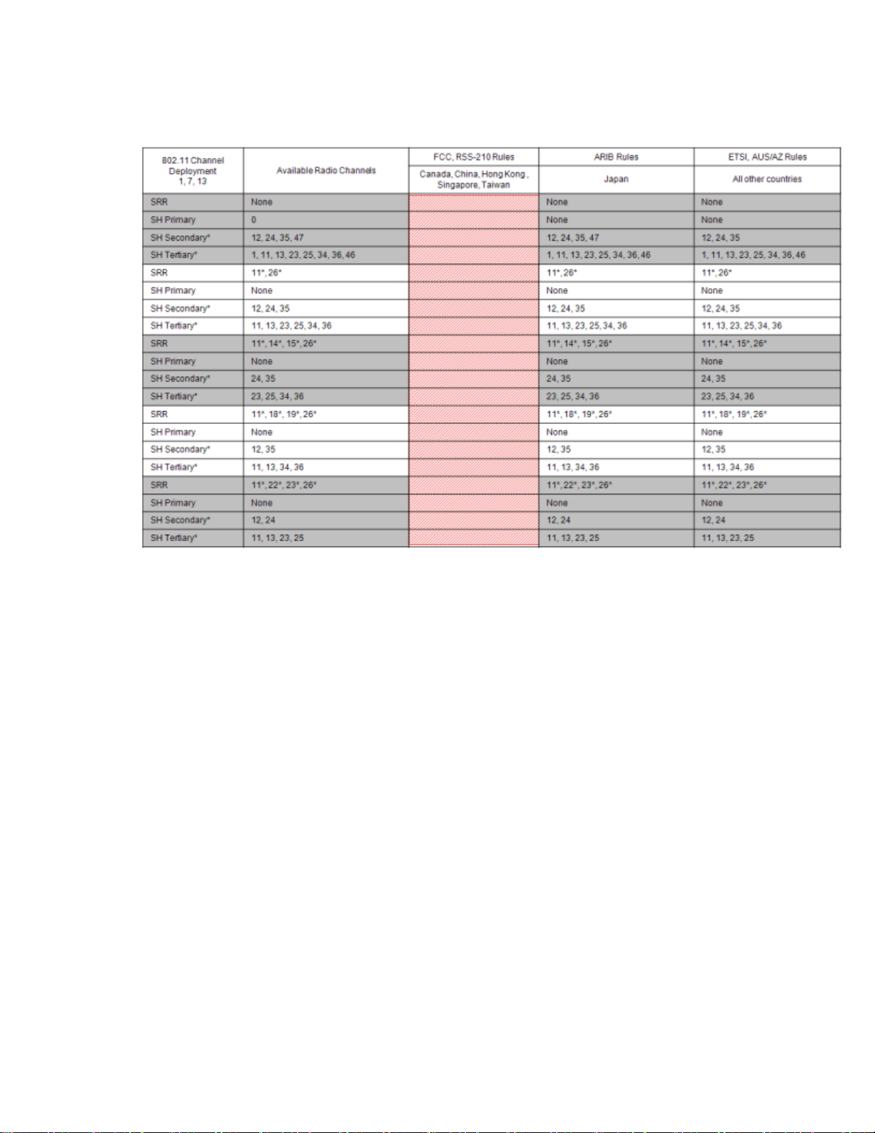
802.11 Channel 1,7,13 Deployment
*Requires RF Frequency Survey and RF Power Level Check for clear channels. Clear SRR channels have a power level < -80dB. Clear Smart-hopping
channels have a power level < -90dBm.
2-16 Installation
Page 27
802.11 Channel 1,5,9,13 Deployment
*Requires RF Frequency Survey and RF Power Level Check for clear channels. Clear SRR channels have a power level < -80dB. Clear Smart-hopping
channels have a power level < -90dBm.
Installation 2-17
Page 28
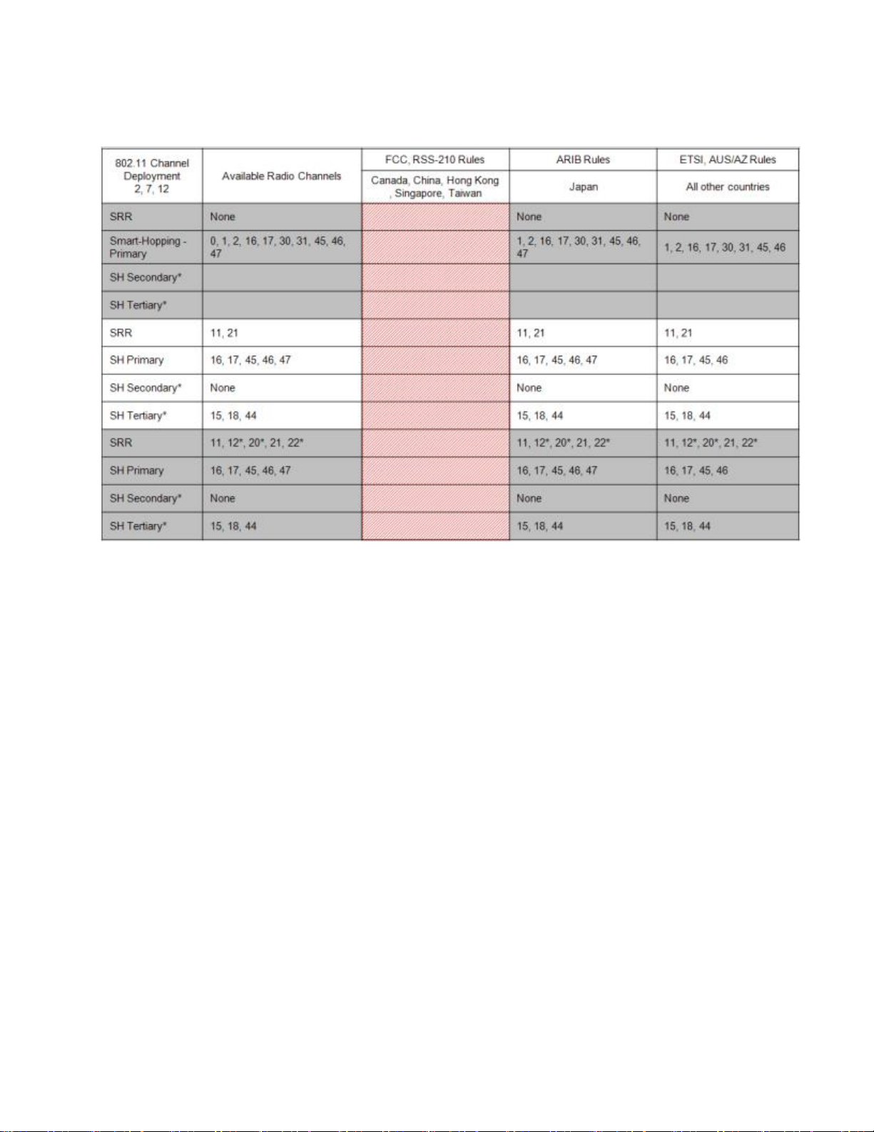
802.11 Channel 2,7,12 Deployment
*Requires RF Frequency Survey and RF Power Level Check for clear channels. Clear SRR channels have a power level < -80dB. Clear Smart-hopping
channels have a power level < -90dBm.
2-18 Installation
Page 29
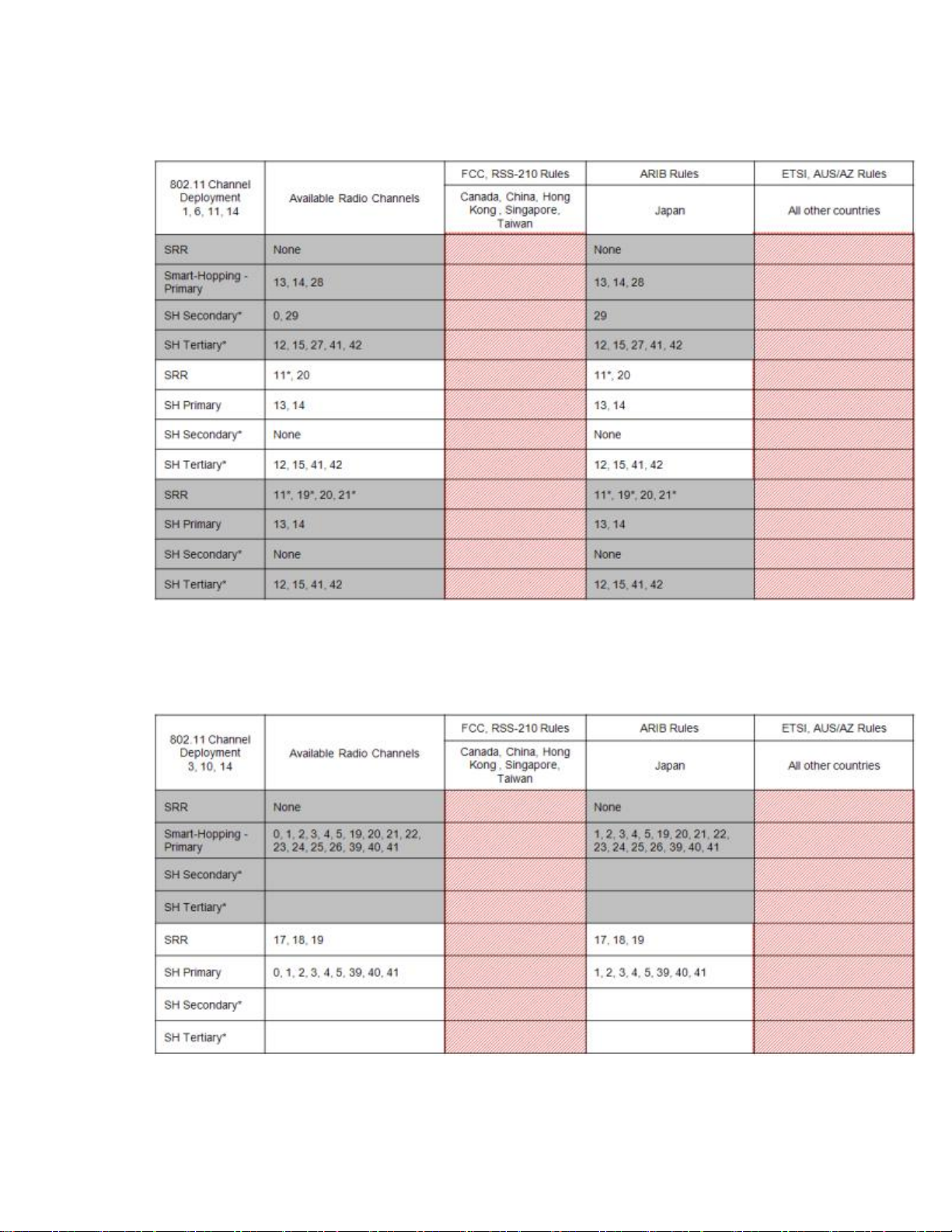
802.11 Channel 1,6,11,14 Deployment
*Requires RF Frequency Survey and RF Power Level Check for clear channels. Clear SRR channels have a power level < -80dB. Clear Smart-hopping
channels have a power level < -90dBm.
802.11 Channel 3,10,14 Deployment
*Requires RF Frequency Survey and RF Power Level Check for clear channels. Clear SRR channels have a power level < -80dB. Clear Smart-hopping
channels have a power level < -90dBm.
Installation 2-19
Page 30
Device Density per SRR
Channel
1.4GHz Smart-hopping
Systems
2.4GHz Smart-hopping
Systems
Maximum density of SRR
Device Links in a single
SRR cell
4 Device Links
3 Device Links
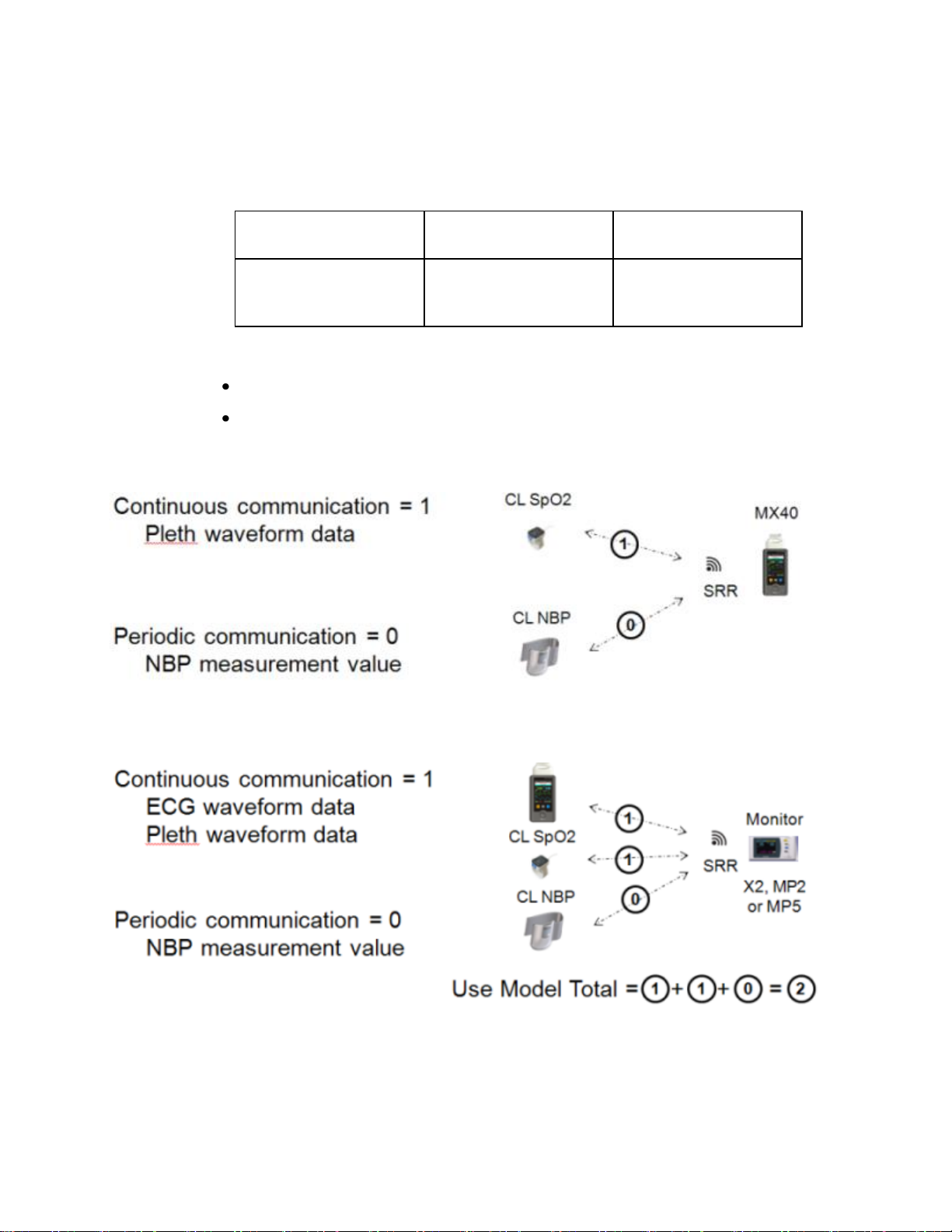
Short-Range Radio Density
A Short Range Radio cell is defined as a radius of 20ft (6.1m).
A "Device Link" is defined by use model.
MX40 is coordinating SRR communication with the Cableless
Measurements:
Patient Monitor is coordinating SRR communication with the
MX40 and Cableless Measurements:
2-20 Installation
Page 31

MX40 Test & Inspection Matrix ............................................................... 3-2
3. Test and Inspection
This section covers Test and Inspection tasks to be performed to ensure the
performance of the MX40 after all Installation procedures are completed.
Test and Inspection 3-1
Page 32

Test Block
Name
Test or "Inspection" to Perform
What to Record
on Service
Record
Visual Test:
Inspect the system (and packing material if applicable)
for obvious signs of damage. Also check external leads
and accessories.
Expected Test Results: The system does not have any
obvious signs of damage = Pass
V:P or
V:F
where P=Pass
F=Fail
Power On:
Remove leadset. Insert battery into the MX40. The MX40
will go through its self-test and pass. Make sure that an
ECG wave appears on the screen and the battery gauge
displays battery status. Check the INOP Area for any
equipment malfunctions.
The expected test result is pass: the MX40 boots up and
displays an ECG wave and the battery gauge displays
battery status. The wave will be a flat line if no simulator
is attached.
Expected Test Results: Expected answer is "yes". If so,
Power On test is passed.
PO:P or
PO:F
where P=Pass
F=Fail
Performance:
1. Insert battery into the MX40 for the channel being
tested.
2. Attach an ECG leadset to the MX40 and an ECG
simulator.
3. At the Information Center assign the MX40 being
tested to a Sector. Ensure that the Multi-Function
Button is turned "on", and turn on the SpO2
parameter if the MX40 being tested has the SpO2
option. Set the mode to Continuous.
4. An ECG waveform should be visible at the
Information Center.
5. If the MX40 has the SpO2 option, connect an SpO2
sensor and apply the SpO2 sensor to yourself.
Confirm that the MX40 completes a successful
measurement.
P:P or
P:F
where P=Pass
F=Fail
6 .Set the SpO2 mode to the customer's desired setting,
Continuous or Spot Check.
7. Place the device in Standby. At the Information
Center, resume monitoring.
MX40 Test & Inspection Matrix
3-2 Test and Inspection
Page 33

Test Block
Name
Test or "Inspection" to Perform
What to Record
on Service
Record
8. Press the Multi-Function Button on the MX40. The
button press should generate one of the following,
depending on the configured setting:
Nurse Call & Record - Nurse Call alarm and a
recording generated at the Information Center.
Nurse Call Only - Nurse Call alarm at the Information
Center.
Record Only - A recording generated at the
Information Center.
Disabled - No event at the Information Center.
9. If the MX40 has the Short-Range Radio option,
establish communication between the MX40 and either
the patient monitor or a cableless measurement device,
depending on the chosen use model. . If assigned to a
patient monitor, an ECG waveform should be visible on
the monitor. The display on the MX40 will be:
10. If assigned to a cableless measurement device,
initiate a measurement and view it at the Information
Center.
Expected Test Results: Expected answer to all is "yes". If
so, Performance test is passed.
Revision
Check:
Check the revision of the software/firmware in the Device
Info. screen. Check the INOP Area for an "SpO2 Equip
Malf" message which indicates an SpO2 upgrade
failure.The revision reported should match the revision
loaded. You may also check the Status Log at the
Information Center.
Expected Test Results: Expected answer is "yes". If so,
Revision Check test is passed.
RC:P or
RC:F
where P=Pass
F=Fail
Test and Inspection 3-3
Page 34

3-4 Test and Inspection
Page 35

Monitoring Mode ...................................................................................... 4-2
Configuration Mode ................................................................................ 4-22
Service Mode ............................................................................................ 4-24
Demo Mode .............................................................................................. 4-25
4. Operating Modes
This section provides operation information about the MX40 when the
device is in Monitoring Mode, Service Mode, Configuration Mode and
Demo Mode.
Operating Modes 4-1
Page 36

1. Patient Cable
2. Patient Information Area
3. Active Alarms Area
4. INOP Area
5. Measurement Area 1
6. Measurement Area 2
7. Waveform 1
8. Waveform 2
9. Radio/Network/Battery Status
Area
10. Leads Off Status Area
11. Silence Alarms Button
12. SmartKeys Button
13. Main Screen Button
14. Multi-Function Button
Monitoring Mode
Monitoring Mode is the normal operating mode of th MX40 and a
password is not required.
Controls, Indicators and Connectors
This section describes the clinical controls of the IntelliVue MX40. These
controls include buttons, display icons, visual and auditory indicators,
ports, and safety labeling located on the front and back of the device.
MX40 Controls and Indicators
4-2 Operating Modes
Page 37

Button
Function
Initiates a local silence/acknowledgment of
all active alarms when enabled.
Silences the "Find Device" sound.
Note — Alarms at the MX40 can be silenced
from the Information Center.
Button
Function
Displays the SmartKey Menu on the touch
screen.
Button
Function
Activates the Touch Display if touched for two
seconds.
Cycles through the display screens if touched
repeatedly.
Resumes from Standby.
Silence Alarm Button
SmartKeys Button
Main Screen Button
SmartKeys
The following table lists the SmartKeys available on the display of the
MX40.
Note—gray text on a SmartKey signifies that the item is unavailable.
Operating Modes 4-3
Page 38

SmartKey
Function
Start SpO2
Note — This
SmartKey is
unavailable
when SpO2
mode is
continuous.
Starts a manual SpO2 measurement.
Delay Record
Starts a delayed recording at the
Information Center.
Alarms
Review of up to 50 previous alarm
conditions (entries are stored during
power cycle). Pause Alarms for
configured time period (if enabled at
the Information Center).
Mode:
Telemetry /
Mode: Monitor
Toggles between modes. In
Telemetry Mode, display and audio
are off; in Monitor Mode, display and
audio are always on.
Standby
Puts the device into standby locally
and at the Information Center.
Displays purchased/enabled product
options.
Add/Remove
Displays available monitors and
IntelliVue Cableless Measurements
to assign to via the short-range radio.
Print Reports
Prints the pre-configured report as
designated at the Information Center.
Vitals Trends
(Optional)
View up to 24 hours of tabular trend
data.
Screen Setup
Determines time period that the
display remains active after user
interaction.
Lock/Unlock
Locks/Unlocks the display.
Op Mode
Selects either Monitoring, Demo,
Config or Service modes.
4-4 Operating Modes
Page 39

The Alarm Area of the MX40 displays
physiological alarms and technical alarms.
A multiple alarm indicator (down arrow) is
displayed when multiple alarm conditions
are present.
A check mark in front of the alarm text
signifies that the alarm has been
acknowledged by touching the Silence
Alarms button.
Alarm Indicators display in the Patient
Information Area in place of the time clock
when alarm/INOP conditions are present
but have not been acknowledged.
Touching the Alarms Area displays a list of
all active alarms.
The alarms paused icon communicates
whether the alarm system is on/off.
Local Alarm Audio is off when the alarm
volume symbol is present.
Alarms Area
Operating Modes 4-5
Page 40

The Patient Information Area displays the following information:
Bed Label
Patient Name (up to 15 characters will display)
Time
Touching the Patient Information Area displays the Patient Demogr. menu which lists
the following:
Patient Name (Last, First, Middle)
Lifetime ID
Encounter ID
Patient Category
Paced Mode
Height
Weight
Date of Birth
Gender
Note — If you use an alternative ID, it will display at the Information Center and on
printed reports. It will not display at the MX40.
1. Pacing algorithm is on.
2. Pacing algorithm is off.
The Lock symbol appears in the lower left of the display when
the MX40 is in a locked state after five minutes of non-use.
Locking the display provides additional protection against
accidental patient access. The display is unlocked using the
SmartKeys menu.
Patient Information Area
Paced Status
4-6 Operating Modes
Display Lock
Page 41

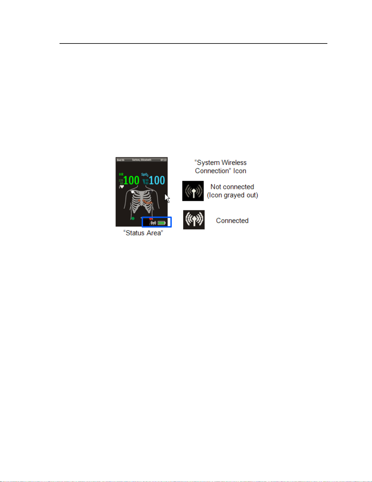
The status area of the MX40 displays short-range radio
connection (optional) and system wireless connection
status. You can also view battery strength for the type
of battery used in the device, AA or rechargeable
Li-on.
Button
Function
Depending on configuration at the Information
Center:
generates a Nurse Call;
Initiates a Delayed Recording;
Both, or;
None
Note — the Multi-Function Button does not operate
when paired with an IntelliVue Patient Monitor via
the short-range radio connection.
Status Area
Multi-Function Button
Operating and Navigating
The principle method of operating your MX40 is via the Touch Display.
Almost every element on the display is interactive. Display elements
include measurement numerics, information fields, alarm fields,
waveforms, SmartKeys and menus.
Power-On Self Test
Once battery power is supplied, the MX40 performs a power-on self test to
check operational status prior to start-up. Should a failure be detected, an
INOP tone will sound and if possible, the appropriate INOP message for
the failure will be communicated to the Information Center and displayed
locally.
Operating Modes 4-7
A successful power-on self test will then transition the MX40 to the start-up
screen. Selectable background colors can be configured and display on the
screen for assistance with device identification. This can be helpful when
devices are in a pooled use setting.
Page 42

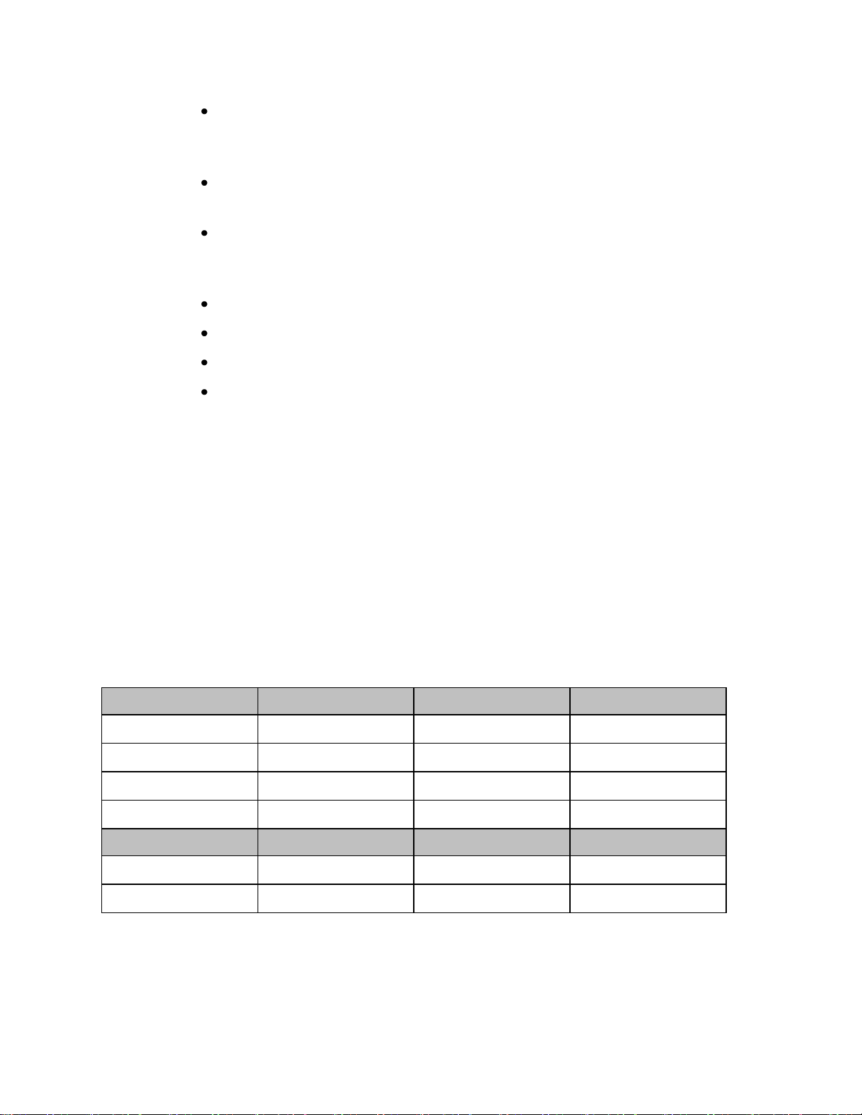
Function
Display
Locked/Active
Display
Locked/Inactive
Display
Unlocked/Active
Display
Unlocked/Inactive
Display Touch
No
No
Yes
No
Main Screen
Button
No
Yes
Yes
Yes
SmartKeys Button
Yes
No
Yes
No
Silence Button
No
No
Yes
No
If the MX40 enters a continuous "boot-up" cycle or the main display does
not appear or update, ensure that you are using a freshly charged
lithium-ion battery or new disposable batteries. If the batteries are fresh and
the device reboots or does not update, remove the device from service.
You must visually check that a waveform is present on the display. You can
access further status information is by touching the status area on the
display.
Navigating
Touching the Navigation Bar on the right of the display will scroll through
additional display items. Solid downward arrows indicate there are
additional elements that are not currently displayed. The arrows briefly
illuminate when touched. Your selection from the menu also illuminates
when touched.
Selecting Display Elements
Touch a display element to get to the actions linked to that element. For
example, touch the Patient Information element to call up the Patient Info
window, or touch the HR numeric to call up the Setup ECG menu. Touch
the ECG waveform to call up the wave selection menu.
Locking the Display
To provide additional protection against accidental patient access to the
MX40, the display can be locked using the Lock SmartKey. When Lock is
selected, the SmartKey menu automatically changes to the Main Screen.
When Unlock is selected, you must close the SmartKey menu to return to
the Main Screen.
The display automatically locks when there is no interaction for five
minutes.
4-8 Operating Modes
Page 43

Measurement Area
The measurement area of the MX40 display is optimized to show available
parameter numerics, waveforms, and alarm limits. Each element is a touch
object and when you select it, further controls and menus become available.
Measurement Area Display Configurations
The display of your MX40 is configured/can operate in one of four available
orientations:
Portrait - One Waveform and four Numerics
Portrait - Two Waveforms and two Numerics (IIC Release N only)
Landscape - Two Waveforms and three Numerics (IIC Release N only)
Portrait - Viewable Chest Diagram and two Numerics
Connecting/Disconnecting the Patient Cable
The patient cable is connected to the MX40 as shown in the illustration
below.
When connecting to the MX40, there is a slight clicking sound that signifies
that the cable is securely connected.
Operating Modes 4-9
Page 44

Disconnect the patient cable as shown below.
Caution
Never disconnect the patient cable by pulling on the leadwires, as this may
damage wires over time.
Understanding Settings
Each aspect of how the MX40 works and looks is defined by a setting. There
are a number of different categories of settings, including:
Screen Settings - to define the selection and appearance of elements on
each individual display screen.
Measurement Settings - to define setting unique to each measurement,
e.g. high and low alarm limits.
Monitor Settings -including settings that affect more than one
measurement or display screen, for example alarm volume and alarm
pause time.
You must be aware that, although many settings can be changed during
use, permanent changes to settings can only be done in Configuration
Mode. All settings are restored to their default setting when the patient is
discharged or the MX40 is powered off.
Changing Measurement Settings
Each measurement has a setup menu in which you can adjust its settings.
You enter the setup menu by selecting the measurement numeric.
4-10 Operating Modes
Page 45

Setting
Description
Alarm Limits
Heart Rate alarm limits can be viewed locally
at the MX40. Limits set at the Information
Center (Release N or later) are reflected at
the MX40 when connected on the network.
Primary
(used for arrhythmia analysis only)
I,II, III, aVR, aVL, aVF, V1-V9, MCL, V3R,
V4R, V5R. Available waveforms are based
on lead set type. Lead II is the default.
Secondary
(used for arrhythmia analysis only)
I,II, III, aVR, aVL, aVF, V1-V9, MCL, V3R,
V4R, V5R. Available waveforms are based
on lead set type. Lead V is the default.
Paced Mode
Yes, No
Adjust Size
Set ECG gain to x1/2, x1, x2, x4
Arrhythmia
Initiate an Arrhythmia Relearn; View
Arrhythmia Alarm Limits; Turn Arrhythmia
Annotation On/Off.
Lead Placement
Set EASI, Standard
ECG
Set ECG On/Off
New Lead Setup
When IntelliVue Patient Monitor lead sets are
in use, select 3-wire, or 5-wire.
Va Lead
Shows position of Va, or C1, electrodes.
Choices are V1-V9, v3R, V4R, V5R.
Vb Lead
Shows position of Vb,or C2, electrodes.
Choices are V1-V9, v3R, V4R, V5R.
Change Numeric
Selects parameter numeric to display in
place of current HR numeric.
ECG Settings at the MX40
Operating Modes 4-11
Page 46

Setting
Description
Wave 1
Primary, Secondary, I, II, III, aVR, aVL, aVF,
V1-V9, MCL, V3R, V4R, V5R. Available
waveforms are based on patient cable type.
Lead II is the default. If Primary or Secondary
are selected, then the waveform displayed is
the waveform configured as primary or
secondary for arrhythmia analysis.
Wave 2
Primary, Secondary, I,II, III, aVR, aVL, aVF,
V1-V9, MCL, V3R, V4R, V5R, Pleth (if SpO2
is available). Available waveforms are based
on patient cable type. Lead V is the default.If
Primary or Secondary are selected, then the
waveform displayed is the waveform
configured as primary or secondary for
arrhythmia analysis.
Waveform Settings at the MX40
Primary or secondary waveform configuration changes made at the
Information Center change the MX40.
Battery Information
Battery Safety Information
Warnings
The battery compartment door must be closed during defibrillation.
Use the Philips Rechargeable Lithium-ion Battery or 3 Duracell Alkaline
batteries, size AA, MN 1500, 1.5V, to ensure specified performance and
correct battery gauge reporting. Outdated, mismatched, or poor-quality
batteries can give unacceptable performance (e.g., insufficient
Battery-Low warning time). If you are using disposable batteries, the
use of fresh high-quality alkaline batteries is strongly recommended.
Certain failure conditions, such as short circuits, can cause a battery to
overheat during use. High temperatures can cause burns to the patient
and/or user. If the MX40 becomes hot to the touch, remove it from the
patient and place it aside until it cools. Then remove the batteries and
discard them. Have the MX40 checked by your service provider to
identify the cause of overheating.
If you receive a TELE BATTERY LOW, TELE BATTERY EMPTY,
REPLACE BATTERY T, or TELE BATTERY TEMP alarm, the batteries
must be promptly replaced. If these conditions are not corrected, they
4-12 Operating Modes
will result in a device shutdown and cessation of monitoring.
Page 47

Activity
When to Perform
Perform a visual inspection.
Before inserting a battery in the
MX40.
Charge the battery.
Upon receipt, after use, or if a low
battery state is indicated. To optimize
performance, a fully (or almost fully)
discharged battery should be charged
as soon as possible.
Clean the battery
At each patient discharge, or in cases
when the battery is exposed to
contaminants.
Charge stored batteries to at least
40% of their capacity every six
months.
When not in use for an extended
period of time.
Decommission the battery
When any of the following INOPs are
displayed on the MX40:
TELE SERVICE BATTERY
TELE BATTERY TEMP
Disposable batteries should be removed from the MX40 at the end of
the battery’s useful life to prevent leakage.
If battery leakage should occur, use caution in removing the battery.
The leaked substance may cause eye or skin irritation. Avoid contact
with skin. Clean the battery compartment according to the instructions
in the Maintenance section. Wash hands.
To eliminate the risk of electrical shock or burn, do not carry loose
batteries on your person, e.g. in clothing pockets.
Caution
Use of AA Lithium batteries or batteries with terminal voltage >1.6V may
cause damage to the device.
Lithium-ion Rechargeable Battery Care
Care of the rechargeable battery begins when you receive a new battery for
use and continues throughout the life of the battery. The table below lists
battery care activities and when they should be performed.
Operating Modes 4-13
Rechargeable batteries are charged using the IntelliVue CL Charging
Station. For information on charging station use, see Charging Li-ion
Rechargeable Batteries p. 5-7 .
Page 48

Note — The battery capacity of re-chargeable batteries degrades over time
and number of recharge cycles. Toward the end of its useful life, the battery
capacity may be reduced by 25-30%. If this reduced battery life is
unacceptable based on your use model, Philips recommends replacing the
rechargeable battery sooner.
Lithium-ion Rechargeable Battery Storage
When storing rechargeable batteries, make sure that the battery terminals
do not come into contact with metallic objects or other conductive
materials.
If batteries are stored for an extended period of time, they should be stored
in a cool, dry place, ideally at 15oC (60oF), with a state of charge of 20% to
40%. Storing batteries in a cool place slows the aging process.
The batteries should not be stored at a temperature outside the range of
-20oC (-4oF) to 50oC (122oF).
Stored batteries should be should be charged to at least 40% of their
capacity every 6 months.". They should be charged to full capacity prior to
use.
Note — Storing batteries at temperatures above 38
o
C (100oF) for extended
periods of time could significantly reduce the batteries' life expectancy.
Lithium-ion Rechargeable Battery Handling Precautions
Lithium-ion batteries store a large amount of energy in a small package.
Use caution when handling the batteries; misuse or abuse could cause
bodily injury and/or equipment damage.
Do not short circuit - take care that the terminals do not contact metal
(e.g. coins) or other conductive materials during transport and storage.
Do not crush, drop or puncture - mechanical abuse can lead to internal
damage and internal short circuits that may not be visible externally.
Do not apply reverse polarity.
Do not incinerate batteries or expose them to temperatures above 60
(140oF).
o
C
If a battery has been dropped or banged against a hard surface, whether
damage is visible externally or not:
discontinue use.
dispose of the battery in accordance with the disposal instructions.
4-14 Operating Modes
Page 49

Inserting/Removing Batteries
Warning
Arrhythmia relearning is initiated whenever the MX40 is powered down
for one minute or longer. Be sure to check your patient’s arrhythmia
annotation for accuracy whenever relearn has occurred.
Caution
Remove the batteries before storing the MX40 for an extended period of
time.
The battery compartment is located on the back of the MX40, accessible by
opening the compartment door from the bottom. It accommodates three
AA 1.5V Alkaline batteries or the Philips Rechargeable Lithium-ion battery.
Only these batteries should be used.
Note— Lithium-ion batteries should be fully charged prior to first use.
Important— Do not use other rechargeable batteries. Use of this type of
battery will adversely affect:
Battery gauge performance
Battery low warnings
Battery life performance
Inserting Batteries
Insert the rechargeable lithium-ion battery using the
following procedure:
Open the battery compartment by lifting up on both bottom sides of the
compartment door.
1 Remove the AA battery tray if present.
Operating Modes 4-15
Page 50

2 Insert the battery pack so that the raised tab is aligned with the cutout
in the base of the battery compartment. Close the battery compartment
door.
3 Close the battery compartment door.
4 Watch for the start-up screen on the front of the MX40 to illuminate
briefly.
Insert AA batteries into the MX40 using the following
procedure:
1 Open the battery compartment by lifting up on both bottom sides of the
compartment door.
2 Insert the AA battery tray if not already present.
3 Insert three AA 1.5V Alkaline batteries, matching the polarity with the
+indications inside the compartment.
Note—all batteries are inserted with the + polarity in the same direction.
4-16 Operating Modes
Page 51

4 Close the battery compartment door.
5 Watch for the start-up screen on the front of the MX40 to illuminate
briefly.
Removing the Batteries
Batteries should be removed when the MX40 is not in use or is being stored.
To remove the batteries, open the battery compartment door and push from
the opening at the bottom of the compartment to pop the batteries out.
Device settings (patient cable type, SpO2 mode, volume, etc.) are retained
when the batteries are removed.
If you remove good AA batteries to turn off the MX40, keep them together
as a set for later re-use so that all batteries will have the same level of power
remaining.
Important— Do not "store" disposable AA batteries by leaving them in the
incorrect polarity position in the MX40.
Be careful not to short circuit the batteries. Batteries can get hot when
shorted. Short circuits are caused when a piece of metal touches both the
positive and negative terminals simultaneously. More than a momentary
short circuit will generally reduce the battery life. In case of a short circuit,
discard the batteries, or just the shorted one if the batteries are new.
Operating Modes 4-17
Page 52

Approximate
Battery Life
Remaining
Approximate
Time
Remaining
(ECG only)
Approximate
Time
Remaining
(ECG & Spo2
Continuous)
Functionality
Disabled
Battery
Indicator LCD
Segments
100%
~ 24 hours
~ 9 hours
None
5 Green
75%
< 18 hours
< 7 hours
None
4 Green
50%
< 12 hours
< 5 hours
None
3 Green
25%
< 6 hours
< 2 hours
None
2 Green
10%
< 2 hours
< 1 hours
None
1 Green
Low battery
level to
replace/charge
battery level
< 30 minutes
< 30 minutes
SpO2 and
short-range
radio are
disabled.
Display is at
half
brightness.
1 Red
Red Battery
Icon
Audio
Replace/charge
battery level
< 10 minutes
< 10 minutes
Device
shutdown
1 Red
Red Battery
Icon
Disposal of Batteries
When disposing of batteries, follow local laws for proper disposal. Dispose
of batteries in approved containers. If local regulations require you to
recycle batteries, recycle batteries in accordance with those regulations.
Battery Charge Status
The battery charge indicator displays in the Status Area and communicates
the remaining battery charge time when using both AA batteries or the
rechargeable lithium-ion battery.
When the MX40 is initially powered-on, it takes approximately 25 seconds
for the indicator to populate. During this time, the indicator displays a ? in
the battery icon.
In order to guarantee overall device performance, certain functionality is
disabled when the battery charge reaches critical levels. See the tables
below for additional information about battery status.
AA Battery Charge Status
4-18 Operating Modes
Page 53

Approximate
Battery Life
Remaining
Approximate
Time
Remaining
(ECG only)
Approximate
Time
Remaining
(ECG & Spo2
Continuous)
Functionality
Disabled
Battery
Indicator
LCD
Segments
100%
~ 25 hours
~ 14 hours
None
5 Green
75%
< 19 hours
< 10.5 hours
None
4 Green
50%
< 13 hours
< 7 hours
None
3 Green
25%
< 6 hours
< 3.5 hours
None
2 Green
10%
< 3 hours
< 1.5 hours
None
1 Green
Low battery
level to
replace/charge
battery level
< 30 minutes
< 30 minutes
SpO2 and
short-range
radio are
disabled.
Display is at
half
brightness
1 Red
Red Battery
Icon
Audio
Replace/charge
battery level
< 10 minutes
< 10 minutes
Device
shutdown
1 Red
Red Battery
Icon
Lithium-ion Rechargeable Battery Charge Status
Operating Modes 4-19
Page 54

Service Information Availabe in Monitoring Mode
While the MX40is operating in Monitoring Mode, important Service
information is available by touching the Status Area. You can view radio
signal strength and device specific information, such as serial number and
software and hardware revisions.
4-20 Operating Modes
Page 55

Operating Modes 4-21
Page 56

Setting
Description
MX40 with IIC N
MX40 with IIC L/M
Touch Tone
Volume:
Audio feedback for
button touch events.
Mute (0) or allow
sound feedback
0 -10
4
0-10
4
Default Screen:
Screen displayed after
power on
1 wave - P(ortrait)
2 waves - P(ortrait)
2 waves L(andscape)
Chest Diagram
1 wave - P(ortrait)
Chest Diagram
Screen Color:
The color of the
Standby screen can
be changed. This can
be used to distinguish
devices between
different units, e.g.
Blue for CCU, Green
for ED
Blue, Gray, Green,
Pink, Purple, Yellow
Note — Blue, Gray,
and Green apply to
both Startup and
Standby screens.
Pink, Purple and
Yellow apply to
Standby screen
only.
Blue, Gray, Green,
Pink, Purple, Yellow
ECG Cable
Color:
These are the colors
that will be displayed
on the chest diagram
if a patient cable type
cannot be determined.
AAMI, IEC
AAMI, IEC
Alarm Sounds
Sets MX40 alarm
sound type to
Traditional (Carenet)
or ISO.
Traditional, ISO
Traditional, ISO
Configuration Mode
This section describes settings that are configured using the user interface
on the MX40. For information on configuration settings that are entered at
the Information Center, see the IntelliVue Information Center Configuration
Guide contained on the MX40 Documentation CD, p/n 453564255041.
Configuration Mode is password protected. The password to enter is
"71034".
Clinical Configuration
The table below lists the settings that are configured using the
Configuration menu:
4-22 Operating Modes
Page 57

Setting
Description
MX40 with IIC N
MX40 with IIC L/M
Alarms On:
Enable: All MX40/IIC
Release N features
available.
Disable: MX40
operates as if
connected to IIC
Release L/M.
Disable, Enable
Disable
Unit Defaults:
Setting
Description
MX40 with IIC N
MX40 with IIC L/M
Alarm Volume
for Off
Network:
Sets the default alarm
volume when the
device goes off
network
10 only
10 only
Inop Reminder:
Inop reminders on or
of
Set at IIC
On, Off
Inop Severity:
ECG Leads
Off
Replace
Battery
Sets the severity of
the "ECG Leads Off"
and/or "Replace
Battery" INOP
conditions
Set at IIC
Red, Yellow, Cyan
Setting
Description
MX40 with IIC N
MX40 with IIC L/M
Lead
Placement:
Sets the default lead
placement to either
Standard or EASI
ECG. This impacts the
leads that are
selectable and the
location of the
electrodes displayed
on the Chest Diagram.
Standard, EASI
Standard, EASI
SpO2 Mode:
Sets the default SpO2
mode to either Manual
or Continuous.
Manual, Continuous
Manual, Continuous
The table below lists the settings that are configured using the SmartKeys menu:
Operating Modes 4-23
The table below lists the settings that are configured using the individual parameter Setup menus
for ECG and SpO2:
Default Settings = Bold.
Note — The IntelliVue Support Tool - Mark 2 can be used to copy the configuration of one MX40
to another MX40.
Page 58

Enabled Product Option #
Product Option
S01
ECG only
S02
ECG and SpO2
S03
ECG and SpO2 Ready (for future upgrade)
C01
Enhanced Arrhythmia
C03
24 hours of Trends
J46
Short-Range Radio
Service Mode
This section describes the menus and settings accessed from the Service
Operating Mode. Service Mode is password protected. The password to
enter is "1345".
Setup Network
The Setup Network menu allows you to set the RF Access Code for the
MX40.
Revisions
The Revisions menu displays the Device Info menu:
Service #: This is the Service Identification Number located on the back
label and used to identify the device.
S/N: This is the Hardware Serial Number for the device located on the
back label and used to identify the device.
SW Service #: This is the Service Identification Number for the software
version on the device. It can be found on the Software License
Certificate that shipped with the Device.
SW SN: This is the Software License Number. It can be found on the
Software License Certificate that shipped with the device.
Note — Customers should save the Software License Certificate for
future reference.
Appl SW: This is the revision of the software installed and running on
the MX40.
HW Rev: This is the Revision Number for the device hardware.
Options: List of enabled product options on the device.
4-24 Operating Modes
Page 59

Demo Mode
The MX40 has a Demo Operating Mode available for assistance in sales and
training situations. Demo Mode is password protected. The password to
enter is "14432".
In Demo Mode, all menus are accessible, and all buttons and SmartKeys are
operational. There is a simulated ECG wave on the display, and the alarm
system is functional. Data is transmitted to the Information Center and is
labeled "Demo" in the patient sector and on the MX40 in the Leads Off
Status Area.
Operating Modes 4-25
Page 60

4-26 Operating Modes
Page 61

Cleaning ...................................................................................................... 5-2
Disposing of the MX40 ............................................................................. 5-4
Label Assignment for Replacement MX40 ............................................. 5-5
Charging Lithium-ion Rechargeable Batteries ...................................... 5-7
5. Maintenance
This section provides procedures for maintaining the MX40 after
installation, including equipment label assignment, cleaning and battery
care.
Maintenance 5-1
Page 62

Cleaning
The procedure in this section keeps the MX40 and its accompanying patient
cable clean and provides protection against infectious agents and
bloodborne pathogens. Both the outside and the inside of the MX40 battery
compartment and the patient cable must be kept free of dirt, dust, and
debris.
Important — After exposure, the MX40 and the patient cable must be
cleaned as per the instructions contained herein. Sterilization of the MX40
has been qualified using the STERRAD 100NX System. For more
information and instruction on sterilizing the MX40, refer to the instuctions
provided by the manufacturer. The alternative Steris V-pro process using
hydrogen peroxide vapor is also acceptable.
Perform the following steps to clean the MX40 and the
patient cable of visible surface contamination.
Note — when cleaning, the use of protective gloves is encouraged.
1 Remove the batteries and disconnect the patient cable.
2 If using disposable AA batteries, remove the battery tray and clean
separately.
3 Wipe the MX40 and the patient cable clean by using a cloth dampened
modestly with one of the approved cleaning agents listed in the table
below.
4 Follow the manufacturer's instructions with regard to application
duration.
5 Wipe the M40 and inside the patient cable housing with distilled water
or alcohol to prevent residue build-up.
6 Allow to air-dry, or dry with a non-lint producing cloth.
Cleaning Materials for the MX40
Caution
5-2 Maintenance
Use of abrasive cleaning materials, or disinfectants or cleaning agents
not listed herein, on any part or component of the MX40 may damage
the components.
The Gore-tex patch in the battery compartment of the MX40 can be
damaged by the use of glutaraldehyde and anti-bacterial soap.
Page 63

Cleaner
Active Ingredient
Isopropyl Alcohol
based
Isopropyl Alcohol (>70%)
Hydrogen Peroxide
Hydrogen Peroxide (3%)
Chlorine Bleach
Sodium Hypochlorite (1:10 concentration,
mixed < 24 hours)
Metrex CaviWipes
Isopropyl alcohol (15-18%)
Sodium hydroxide (0.1%)
2-butoxyethanol (1-5%)
Viraguard
Isopropanol (70%)
Resert XL HLD
Hydrogen peroxide (1.4-2-3%)
2-Fumic Acid (<2.5%)
Sporox II Sterilizing &
Disinfection Solution
Hydrogen peroxide (7.5%)
Phosphoric acid (0.85%)
Sanicloth Plus
Germicidal Cloths
Isopropyl alcohol (55%)
Quaternary ammonium (0.5%)
WipesPlus
Disinfecting Wipes
Phenylphenol (0.28%),
Benzyl-p-chlorophenol (0.03%)
TechSpray General
Purpose Cleaner
Isopropyl alcohol (70%)
Oxivir Tb Cleaner
Disinfectant
Hydrogen peroxide (2.5-3.5%)
Oxivir Tb Wipes
Hydrogen peroxide (3%)
Sanicloth HB
Quaternary ammonium (1%)
Sanicloth Plus
Quaternary ammonium (0.25%)
2-Butoxyethol (1-4%)
Isopropyl alcohol (14.85%)
Super Sanicloth
Quaternary ammonium (<1%)
Isopropyl alcohol (55%)
Sharp or pointed instruments should not be used to remove soil from
recessed areas on the MX40.
Approved Cleaners
Note —The cleaners listed above are also suitable for cleaning the patient
cable and the lithium-ion battery.
Maintenance 5-3
Page 64

Disposing of the MX40
Warning
To avoid contaminating or infecting personnel, the environment or other
equipment, make sure you disinfect and decontaminate the MX40
appropriately before disposing of it in accordance with your country's laws
for equipment containing electrical and electronic parts. For disposal of
parts and accessories where not otherwise specified, follow local
regulations regarding disposal of hospital waste.
You will find detailed disposal information on the following web page:
http://www.healthcare.philips.com/main/about/Sustainability/Recycling/p
m.wpd
The Recycling Passports located there contain information on the material
content of the equipment, including potentially dangerous materials which
must be removed before recycling (for example, batteries and parts
containing mercury or magnesium).
Do not dispose of waste electrical and electronic equipment as unsorted
municipal waste. Collect it separately, so that it can be safely and properly
reused, treated, recycled, or recovered.
5-4 Maintenance
Page 65

Label Assignment for Replacement MX40
During installation, an equipment label is assigned to each MX40 in a
clinical unit so that the device can be identified during operation within the
wireless system. If an MX40 is lost, the Assign Label function at the
Information Center enables you to unassign the label from a lost device,
and re-assign its label to a replacement device. Labels are limited to those
available in an individual clinical unit. The Label Assignment function
requires a password for access, and its controls are available in English
only.
Re-assigning an Equipment Label
To re-assign an equipment label to a replacement
device:
1 At the Information Center, clear the sector that the original equipment
label was assigned to (Patient Window -> Sector Setup -> Clear
Sector -> OK).
Note — Before clearing the sector, ensure that the equipment label of
the lost device is not actively assigned to a patient being monitored.
2 Select All Controls -> Label Assignment.
3 Enter password.
Note — The remaining screens will be in English only.
4 Insert battery power into the MX40 and if attached, disconnect the
patient cable.
5 Select Refresh.
6 Select the MAC address of the replacement device from the New
Devices list. If the address does not appear, remove battery power and
re-insert. Select Refresh.
Note — The MAC address appears on the rear label of the MX40.
7 Select the equipment label that was assigned to the previous device
from the Equipment Label list.
8 Select Assign Label to initiate programming of the equipment label
into the replacement MX40.
9 When prompted, press Confirm on the MX40 to accept the assignment.
The confirmation must occur within 30 seconds of the prompt.
Maintenance 5-5
Page 66

10 Wait for the new_device label to change to the selected equipment label.
11 In Sector Setup, select the Bed Label and Equipment Label and then
press OK.
5-6 Maintenance
Page 67

Charging Lithium-ion Rechargeable Batteries
The li-ion rechargeable battery is recharged using the IntelliVue CL
Charging Station.
To charge a battery, place it onto a charger slot on the charging station. The
battery power indicators will supply information about the charge status.
Warning
Always use the supplied power cord with the grounded mains plug to
connect the charging station to a grounded AC mains socket. Never
adapt the mains plug from the power supply to fit an ungrounded AC
mains socket.
Do not use AC mains extension cords or multiple socket outlets. If a
multiple portable socket outlet without an approved isolation
transformer is used, the interruption of its protective grounding may
result in leakage currents equal to the sum of the individual ground
leakage currents, so exceeding allowable limits.
Do not connect any devices that are not supported as part of the system.
Battery Power Indicators
There are various indications which help you keep track of the battery
power status.
LEDs on the charging station slots
battery status information on both the MX40 and the charging station's
display
INOP messages
The indicators always show the remaining capacity in relation to the
battery's actual maximum capacity which may lessen as the battery ages.
Charging Station LEDs
The nine charger slot LEDs show the battery status of the device in their
slot and are switched off if no battery is inserted.
If a battery is put on a charging station slot, the corresponding LED will
flash yellow until the battery's current state has been identified. Then a
beep is issued and the LED reflects the battery status as described in the
table below.
Maintenance 5-7
Page 68

Status
LED
no battery on charger slot
off
battery put on charger slot
flashing yellow
battery not properly recognized,
error
cyan
battery recognized, battery
charging
yellow
battery recognized, battery full
(>90%)
green
The AC Power / Error LED is
green when the charging station is connected to AC power
cyan during startup or to indicate a general charging station error
Note — Wiping of battery contacts with an alcohol solution after cleaning is
recommended.
Battery Status on the Charging Station Display
The IntelliVue CL Charging Station display provides a quick overview of
all the connected devices and their battery status. The screen is arranged in
the same layout as the charger slots.
Battery Lifetime Management
The lifetime of a li-ion battery depends on the frequency and duration of
use. When properly cared for, the useful life is approximately 4 years or 500
complete charge-discharge cycles, whichever comes first. In addition,
experience indicates that the incidence of failure may increase with battery
service life due to the accumulated stresses of daily use. We therefore
strongly recommend that li-ion batteries be replaced after 2 years or 500
complete charge-discharge cycles.
5-8 Maintenance
The age of a li-ion battery begins at the date of manufacture. The date of
manufacture is listed on the side of the battery.
Page 69

Battery Disposal
Discharge the battery and insulate the terminals with tape before disposal.
Dispose of used batteries promptly and in accordance with local recycling
regulations.
Maintenance 5-9
Page 70

Page 71

MX40 Product Structure ........................................................................... 6-2
MX40 Support Parts .................................................................................. 6-5
6. Part and Option Ordering
Information
This section provides specific part number, option number. support part
number, and descriptive information associated with the MX40.
Part and Option Ordering Information 6-1
Page 72

Standard
Optional
MX40
865350
MX40
865351
WMTS 1.4 GHz Smart-hopping network
2.4 GHz Smart-hopping network
Rechargeable battery
AA batteries
Required additional purchases1
S01
ECG only
S02
ECG + Fast SpO2 enabled2
S03
Fast SpO2 ready3
Add-on options
Clinical applications
C01
Enhanced Arrhythmia4
C03
Vitals Trend
Documentation
D01
Paper instructions for use5
Interfaces
J46
Short range radio
865349
Intellivue MX40 accessories
Device accessories
E24
MX40 Lith-ion battery, pkg of 3
E28
AA battery, 8 pieces6
E29
Carry pouch, pkg of 50
Patient accessories
K03
ECG 3-lead grabber, AAMI MX40
MX40 Product Structure
The table below provides MX40 part and option information.
6-2 Part and Option Ordering Information
Page 73

Standard
Optional
MX40
865350
MX40
865351
K05
ECG 5-lead grabber, AAMI MX40
K06
ECG 6-lead grabber, AAMI MX40
K07
ECG 3-lead grabber, AAMI + SpO2 MX40
K08
ECG 5-lead grabber, AAMI + SpO2 MX40
K09
ECG 6-lead grabber, AAMI + SpO2 MX40
K13
ECG 3-lead grabber, IEC MX40
K15
ECG 5-lead grabber, IEC MX40
K16
ECG 6-lead grabber, IEC MX40
K17
ECG 3-lead grabber, IEC + SpO2 MX40
K18
ECG 5-lead grabber, IEC + SpO2 MX40
K19
ECG 6-lead grabber, IEC + SpO2 MX40
K23
MX40 extender cable
K24
Adapter cable bedside/MX40 ECG + SpO2
Additional accessories
98980317222
1
ECG trunk cable AAMI/IEC
98980317182
1
ECG 5-lead snap AAMI
98980317184
1
ECG 5-lead snap AAMI+SpO2
865220
Battery charging station7
1 Only one of this category must be chosen.
2 Requires purchase of pulse oximetry accessories. May require adapter cable.
3 Requires purchase of 865348/S02 to enable feature.
4 Not applicable for IntelliVue Information Center release L or M.
5 Applicable for the United States only.
6 Support for disposable batteries is standard. Must purchase AA batteries
separately.
7 Requires purchase of 865349/E24.
Part and Option Ordering Information 6-3
Page 74

Standard
Optional
MX40
865350
MX40
865351
865348
IntelliVue MX40 upgrade options
Base Functionality
S02
Enable Fast SpO2 to S03 device
Clinical applications
C01
Add Enhanced Arrhythmia
C03
Add Vitals Trend
Interfaces
J46
Add short range radio
6-4 Part and Option Ordering Information
Page 75

Description
Part Number
86530
86531
TELE PWM, 1.4 GHz,
ECG Only, Exchange
453564262491
S01
n/a
TELE PWM, 1.4 GHz,
ECG and Sp02, Exchange
453564262511
S02 or S03
n/a
TELE PWM, 2.4 GHz,
ECG only, Exchange
453564262531
n/a
S01
TELE PWM, 2.4 GHz,
ECG &Sp02, Exchange
453564262551
n/a
S02 or S03
ASSY - AA Battery
Adapter, Tele PWM
453564132721
All
All
PLAST - Battery Door
w/Gasket
453564205271
All
All
MX40 Rechargeable
Battery, Pkg 1
989803176201
All
All
MX40 Service Adapter +
Cable (tool for service)
453564270071
All
All
Note — The software license transfer process expects the same hardware number as
original device.For example:
A SW license for S01 can only be transferred to 453564262491 or 453564262531.
A SW license for S02 or S03 can only be transferred to 453564262511 or
453564262551.
MX40 Support Parts
Part and Option Ordering Information 6-5
Page 76

Service personnel can find the following information on the label on the
back of the MX40:
6-6 Part and Option Ordering Information
Page 77

Tools Required ........................................................................................... 7-2
Software License Transfer ........................................................................ 7-3
7. MX40 Repair Strategy
The MX40 Repair Strategy is Unit Exchange worldwide through Philips
part centers.
MX40 Repair Strategy 7-1
Page 78

Tools Required
Repair of the MX40 requires the following tools:
MX40 Service Adapter Cable
PC running the IntelliVue Support Tool - Mark2
Internet Connection to the Philips Software License Server
7-2 MX40 Repair Strategy
Page 79

Software License Transfer
The MX40 uses Software Licensing functionality to track customer
information, software revisions, and features enabled. Software Licensing
allows service personnel to easily determine what products, features, and
revisions are installed at a particular customer site.
Exchange devices will arrive without a software license.
The software license from the defective device needs to be transferred to the
exchange device using the IntelliVue Support Tool - Mark2. For more
information, see the Support Tool Instructions for Use, p/n 453564296161.
MX40 Repair Strategy 7-3
Page 80

Note — The MX40 connects to a PC via a USB port and uses a USB cable,
but the MX40 does not operate as a standard USB device. The MX40 does
not support the use of a cable longer than 3 ft. Longer cables may result in
an unacceptable drop in voltage.
7-4 MX40 Repair Strategy
Page 81

Technical Alarms (INOPs) ....................................................................... 8-2
Possible User Interface Issues ................................................................ 8-10
8. Troubleshooting
This section provides information about the technical alarms generated by
the MX40 and associated troubleshooting suggestions. Also provided are
troubleshooting suggetions for user interface issues and information
regarding the patient cables used with the MX40.
Troubleshooting 8-1
Page 82

Alarm Text
Priority
Condition
What to do
BATTERY LOW T
Source - MX40
Soft
There is less than 15
minutes of monitoring
time remaining (AA
batteries).
Lithium-ion battery
level is < 10% or has
<30 minutes
remaining time.
Replace batteries
promptly to avoid
shutdown and cessation of
monitoring.
Insert a charged
lithium-ion battery pack.
CANNOT ANALYZE
ECG
Source - MX40 and
Information Center
Hard
Arrhythmia algorithm
cannot reliably analyze
the ECG data on any
monitored leads.
Assess the lead selections,
initiate relearn, and validate
analyzed rhythm. Check
other INOPs for possible
source of problem.
Technical Alarms (INOPs)
Technical Alarms, or INOPs (inoperative conditions), are sourced at the
MX40, the ST/AR algorithm running at the Information Center, or the
IntelliVue Patient Monitor. They identify inoperative conditions (that is
conditions where the system is not operating properly and therefore cannot
measure or detect alarm conditions reliably). There are four levels of
Technical Alarms:
Severe - Monitoring and alarm generation are disabled. Visual alarm
indicator on the MX40. Audible tone at the Information Center. Must be
acknowledged by a clinician.
Hard - Monitoring and alarm generation are disabled. Visual alarm
indicator on the MX40. Audible tone at the Information Center.
If the hard INOP is "latched", the sound will be silenced, but the
message will remain on the display until resolution of the offending
condition.
Soft - Monitoring and alarms remain active. Visual alarm indicator on
the MX40 and at the Information Center. No audible tones are
generated at the Information Center
Red/Yellow - Replace Battery and ECG Leads Off INOPs may be
configured to display as either Red or Yellow Technical Alarms.
Note - The ECG Leads Off INOP will initially display as a cyan
technical alarm until a valid ECG signal is obtained.
In the following table, technical alarms are listed alphabetically.
8-2 Troubleshooting
Page 83

Alarm Text
Priority
Condition
What to do
CHECK PAIRING
Source - MX40
Yellow
Technic
al Alarm
There is a problem
with device pairing.
When the MX40 is
wirelessly paired with
an X2 patient monitor
(no label) docked with
a larger networked MP
series monitor, and
the network
connection is lost.
Check that the bedside
monitor is correctly paired.
Select the correct device
to be paired.
cl NBP Batt Low
Source - Cableless
Measurement Device
Hard
CL NBP Pod weak
battery condition.
Charge CL NBP Pod.
cl NBP Batt Empty
Source - Cableless
Measurement Device
Severe
CL NBP Pod empty
battery condition.
Monitoring is not
possible.
Replace CL NBP Pod.
Recharge depleted CL
NBP Pod.
cl NBP DISCONNECT
Source - Cableless
Measurement Device
Hard
CL NBP Pod is not
connected with the
MX40.
Resolve interference
condition.
Reduce range between
CL NBP Pod and MX40.
cl SpO2 Batt Low
Source - Cableless
Measurement Device
Hard
CL SpO2 Pod weak
battery condition.
Charge CL SpO2 Pod.
cl SpO2 Batt Empty
Source - Cableless
Measurement Device
Severe
CL SpO2 Pod empty
battery condition.
Monitoring is not
possible.
Replace CL SpO2 Pod.
Recharge depleted SpO2
Pod.
cl SpO2 DISCONNECT
Source - Cableless
Measurement Device
Hard
CL SpO2 Pod is not
connected with the
MX40.
Resolve interference
condition.
Reduce range between
CL SpO2 Pod and MX40.
!!!/!! CUFF NOT
DEFLATED
Source - Cableless
Measurement Device
Severe
Cuff pressure has
exceeded the specified
safety limit.
Remove cuff and tubing and
expel air.
Troubleshooting 8-3
Page 84

Alarm Text
Priority
Condition
What to do
!!!/!! CUFF OVERPRESS
Source - Cableless
Measurement Device
Severe
Cuff pressure has
increased above
overpressure safety
limits.
Remove cuff and tubing and
expel air.
ECG/ARRH ALARM
OFF
Source - MX40
Soft
ECG is turned off.
Turn on ECG.
ECG LEADS OFF
Note This INOP may
also be configured to
display as a Red or
Yellow Technical Alarm.
Source - MX40
Red or
Yellow
or Hard
Technic
al Alarm
Multiple leads are off.
Re-attach ECG leads to
patient..
<electrode> LEAD OFF
Source - MX40
Hard
Single lead is off.
If primary lead is MCL,
lead will be identified as
V/C in INOP text.
Re-attach ECG leads to
patient.
LEADSET UNPLUGGED
Source - MX40
Hard
Patient cable has
been unplugged from
the MX40.
Incompatible leadset
attached to patient
cable.
Re-attach the patient
cable.
Replace the leadset.
LOCAL AUDIO OFF
Source - MX40
Note — This is normal
operation in Telemetry
Mode.
Soft
There is no alarm audio
notification when
operating in Telemetry
Mode.
Change to Monitor Mode.
NBP INTERRUPTED
Source - Cableless
Measurement Device
Hard
The preset maximum
time for the total
measurement has been
exceeded.
Reduce patient movement
and avoid interaction with the
cuff and tubing.
NBP MEASURE FAILED
Source - Cableless
Measurement Device
Hard
Measurement values
cannot be derived.
Attach cuff to new location
on patient.
Replace cuff.
8-4 Troubleshooting
Page 85

Alarm Text
Priority
Condition
What to do
NBP EQUIP MALF
Source - Cableless
Measurement Device
Hard
Tubing may be
obstructed or kinked.
Hardware malfunction.
Check tubing.
If condition persists,
contact Service.
NO ALARM DISPLAY
Source - MX40
Soft
When operating with
Information Center
Release L Or M, there is
no local alarming at the
MX40, networked or
non-networked.
Condition is not present when
operating with Information
Center Release N or later
(unless specifically
configured to operate in this
way).
NO CENTRAL
MONITOR
(appears at MX40 only)
Source - MX40
Hard
The MX40 is out of
range of the network.
Patient Sector at the
Information Center is
in Standby.
Return the MX40 to the
coverage area.
Select Resume at the
Information Center.
NO HOST
MONITORING
Source - MX40
Hard
The paired
MX40/bedside monitor is
out of short-range radio
range or there is
excessive radio
interference.
Reduce the distance
between the devices.
Identify and remove
interference source.
NO SIGNAL
(appears at the
Information Center only)
Source - Information
Center
Hard,
Latched
The MX40 is outside
the coverage area, or
No batteries in the
MX40, or
The MX40 has failed.
Make sure that the MX40
is within the coverage
area and has good
batteries.
Replace the MX40 if
Power On Self Test fails.
Put bed in Standby.
Contact Service
REPLACE BATTERY T
Source - MX40
Note — This INOP may
also be configured to
display as a Red or
Yellow Technical
Alarm.
Red or
Yellow
or Hard
Technic
al
Alarm,
Latched
Dead battery. No
monitoring is
occurring.
When operating
wirelessly, the patient
monitor is no longer
providing power to the
MX40, and battery
capacity is now
depleted.
Replace batteries.
Troubleshooting 8-5
Page 86

Alarm Text
Priority
Condition
What to do
SpO2T EQUIP MALF
Source - MX40
Hard
Malfunction in the SpO2
equipment
Contact Service.
SpO2T ERRATIC
Source - MX40
Hard
Erratic SpO2
measurements, often due
to a faulty sensor or
invalid SpO2
measurements, or
incorrect transducer
position
Repeat measurement,
reposition sensor on patient,
or finally, replace sensor.
SpO2T EXTD UPDATE
Numeric is replaced by a
-?-.
Source - MX40
Soft
The update period of
displayed values is
extended due to an NBP
measurement on the
same limb or an
excessively noisy signal.
If NBP is not active, check
the sensor placement.
Reposition the sensor on
patient, or replace sensor.
SpO2T LOW PERF
Source - Monitor
Soft
Accuracy may be
reduced due to low
perfusion. Data displayed
with ?.
Increase perfusion. Change
sensor site. Avoid site distal
to BP cuff or intra-arterial
line. Warm the site.
SpO2T INTERFERENCE
Source - MX40
Hard
Level of ambient light or
level of electrical
interference are so high
that the SpO2 sensor
cannot measure SpO2
and pulse rate.
Reduce ambient light to
sensor or electrical noise
sources.
SpO2T NO SENSOR
Note — Silencing this
technical alarm turns off
the SpO2 measurement
on the MX40 only (not at
the Information Center).
Source - MX40
Hard
No sensor attached to
SpO2 device.
Attach SpO2 sensor.
%SpO2T NOISY SIGN
Source - MX40
Hard
Excessive patient
movements or electrical
interference are causing
irregular pulse patterns
Reduce movement or
electrical noise sources.
8-6 Troubleshooting
Page 87

Alarm Text
Priority
Condition
What to do
SpO2T NO PULSE
Source - MX40
Note — When paired
directly with an IntelliVue
MP5 Patient Monitor, the
INOP will display as
SpO2T SENSOR OFF.
Hard
Pulse is too weak or
not detectable
Sensor has fallen off
at patient.
Check connection to
patient.
Change sensor site. Avoid
site distal to BP cuff or
intra-arterial line.
SpO2 POOR SIGNAL
Source - MX40
Soft
Although a measurement
may be possible, its
accuracy may be
reduced due to poor
signal quality.
Apply the sensor
according to the
manufacturer's
instructions.
Relocate the sensor to a
different site on the
patient.
SpO2T SEARCHING
Source - MX40
Soft
The patient signal is
analyzed, but a valid
numeric is not available
yet.
Wait for the measurement to
complete.
SpO2T SENSOR OFF
Note — The ability of
the algorithm to detect
this condition depends
on the sensor type in
use.
Hard
The algorithm has
determined that a sensor
is connected, but not
properly applied to the
patient.
Apply the sensor
according to the
manufacturer's
instructions.
If the condition persists,
relocate the sensor to a
different site on the
patient.
SpO2T SENSOR MALF
Source - MX40
Hard
Malfunction of the SpO2
sensor/adapter cable
Replace sensor.
SpO2 UNKN SENSOR
Source - MX40
Hard
The connected SpO2
sensor and/or adapter
cable is not supported by
the hardware version.
Use specified sensor and/or
adapter cable.
SpO2T UPGRADE
Source - MX40
Soft
SpO2 hardware is in
upgrade process.
Monitoring is not
possible.
Wait for the upgrade process
to complete.
TELE BATTERY LOW
Source - MX40
Soft
Lithium-ion battery level
is < 20% or has <30
remaining time.
Insert a charged lithium-ion
battery pack.
Troubleshooting 8-7
Page 88

Alarm Text
Priority
Condition
What to do
TELE BATT EMPTY
Note — This INOP may
also be configured to
display as a Red or
Yellow Technical Alarm.
Source - MX40
Note — For Information
Center Release L or M,
this INOP will appear as
"REPLACE BATTERY
T".
Hard,
Latched
Lithium-ion battery level
is critically low. A
10-minute countdown
begins. The MX40 will
shut down if the condition
is not cleared.
Insert a charged lithium-ion
battery pack.
TELE BATTERY TEMP
Source - MX40
Note — For Information
Center Release L or M,
this INOP will appear as
"REPLACE BATTERY T"
Hard
The temperature of the
lithium-ion battery is
above 55o C or below -5o
C.
Replace the lithium-ion
battery.
TELE CHECK BATT
Source - MX40
Soft
Lithium-ion battery has <
25 charge cycles
remaining before
reaching the charge
cycle maximum limit.
Be aware that the Lithium-ion
battery pack will soon need
replacement.
TELE MALFUNCTION
Source - MX40
Hard
MX40 malfunction or
self-test failure.
Contact Service to replace
the MX40.
TRANSMITTER OFF
Source - MX40
Hard
RF Auto Shutoff after 10
minutes of all leads off
and no SpO2 sensor
connected.
Reattach ECG leads to
patient.
Reattach SpO2 sensor.
TELE REMOVE BATT
Source - MX40
Note — For Information
Center Release L or M,
this INOP will appear as
"REPLACE BATTERY
T".
Hard,
Latched
The temperature of the
lithium-ion battery is >60o
C and the battery must
be removed.
Replace the lithium-ion
battery.
Dispose of old battery
properly.
TELE SERVICE BATT
Source - MX40
Hard
The lithium-ion battery
has exceeded the
maximum charge cycle
limit and reached the end
of its useful life.
Replace the lithium-ion
battery.
Dispose of old battery
properly.
8-8 Troubleshooting
Page 89

Alarm Text
Priority
Condition
What to do
TELE WEAK SIGNAL
Source - MX40
Soft
Patient is at outer
range of the radio
coverage area.
The MX40 is receiving
a weak signal with
high data loss from
the AP.
Condition exists for
multiple devices in a
specific area
Return patient to the
coverage area.
If patient is in close
proximity to AP, replace
the MX40. Contact
service.
The AP covering the
specific area is suspect.
Contact Service
Troubleshooting 8-9
Page 90

Possible User Interface Issues
The MX40 display does not turn on.
The AA Battery Tray may be inserted backwards.
The user may not understand that they need to touch the blue Main
Screen button for two seconds.
The MX40 display does not react to touch.
8-10 Troubleshooting
The screen is locked and needs to be unlocked using the Unlock
SmartKey.
Page 91

The user is not using their finger to touch the screen. The MX40 does
not react to touches by a fingernail, pen, etc.
The MX40 does not not recognize the patient cable type.
The IntelliVue style leadset adapter cable is being used, therefore,
detection of the cable type is not possible. Configure the MX40 for the
desired settings:
ECG Cable Color, using the Configuration Menu in Configuration
Mode.
Lead Placement, using the HR Menu in Configuration Mode.
If using a 3-wire IntelliVue leadset, it must be selected using the Setup
ECG menu and then selecting the New Lead Setup entry. This will
remove the INOP message.
Troubleshooting 8-11
Page 92

Page 93

Regulatory Information ............................................................................ 9-2
Electromagnetic Compatibility ................................................................ 9-6
Battery Specifications .............................................................................. 9-12
Lithium-ion Battery Charge Time ......................................................... 9-15
Physical Specifications ............................................................................ 9-16
MX40 1.4 GHz Radio ............................................................................... 9-17
MX40 2.4 GHz Radio ............................................................................... 9-18
MX40 Short-Range Radio ....................................................................... 9-20
Environmental Specifications ................................................................ 9-21
Measurement Specifications .................................................................. 9-22
9. Safety Standards &
Specifications
This section describes the regulatory standards that the IntelliVue MX40
complies with, along with product and measurement specifications.
Safety Standards & Specifications 9-1
Page 94

Regulatory Information
Software Hazard Prevention
Potential hazards arising from errors in the software program have been
identified. Mitigations applied to reduce the associated risk of such hazards
are included as part of the Risk Management, Clinical Evaluation, and
Verification and Validation phases of the product’s development.
AC Power Source
The system is not intended for connection to the public mains as defined in
CISPR-11.
Industrie Canada Compliance (Canada)
This Class B ISM device complies with Canadian ICES-001.
Cet ISM de la classe B est conforme à la norme NMB-001 du Canada.
Safety Standards
The device complies with the following safety requirements for medical
electrical equipment:
EN 60601-1:1990 + A1:1993 + A2:1995 +A11:1993 +A12:1993 + A13:1996
General Requirements for Safety (with worldwide deviations, including
U.S. deviations)
CSA C22.2 #601.1:1992 Medical Electrical Equipment - General Safety
UL 60601-1 Medical Electrical Equipment - General Safety
UL 2054 Standards for Household and Commercial Batteries
EN 60601-1-1:2006 System Requirements
EN 60601-1-4:2000 Safety Requirements for Programmable Electronic
Medical Systems
EN 50371:2005 Low Power Electronic and Electronic Apparatus
Electromagnetic Exposure
EN ISO 9919:2005 Requirements for SpO2 Pulse Oximeters
EN ISO 10993-1:2003 Biocompatibility
EN ISO 10993-1:2003 Biocompatibility (for leadwires and pouch)
9-2 Safety Standards & Specifications
Page 95

EN ISO 9919:2005 Pulse Oximeters
IEC 60601-1-2:2001 Electromagnetic Compliance
IEC 60601-1-4:1999 +A1 Requirements for Programmable Electrical
Medical Systems
IEC 60601-1-6:2006 General requirements for basic safety and essential
performance - Collateral standard: Usability
IEC 60601-1-8:2006 General Requirements for Safety for Alarm Systems
IEC 60601-2-49:2001 Particular Requirements for Safety for Patient
Monitoring Equipment
IEC 60601-2-27:2005 Particular Requirements for Safety for
Electrocardiograph Monitoring Equipment
IEC 62133:2002 Safety Requirements for Portable Sealed Secondary Cells
(alkaline, lithium-ion)
AAMI EC 13:2007 Performance Standard, Cardiac Monitors
AAMI EC 53:1995 (R) 2001 ECG Cables/Leadwires (excluding 4.2.1)
Intended Use Statement
Intended for monitoring and recording of and to generate alarms for,
multiple physiological parameters of adults and pediatrics in a hospital
environment and during patient transport inside hospitals. Not intended
for home use. Intended for use by health care professionals.
Indications for Use
Indicated for use by health care professionals whenever there is a need for
monitoring the physiological parameters of patients. Intended for
monitoring and recording of, and to generate alarms for, multiple
physiological parameters of adults and pediatrics in hospital environments
and during transport inside hospitals.
Safety Standards & Specifications 9-3
Page 96

Intended Uses of MX40
The MX40 is to be used primarily as a traditional telemetry medical device.
It connects to the IntelliVue Information Center by way of a wireless
network. When the MX40 is connected the IntelliVue Information Center
the IntelliVue Information Center provides the primary patient monitoring
and alarming function. The MX40 does not automatically provide local
monitoring or alarming when connected to the Information Center.
The MX40 can provide time-limited local monitoring when it is not
connected to the wireless network.
Unlike a traditional bedside monitor which operates on AC power, the
MX40 is powered by battery and cannot provide continuous monitoring.
Authorized EU Representative
Philips Medizin Systeme Deutschland
Hewlett-Packard-Strasse 2
D 71034, Boeblingen
Germany
Patient Population
This device is not for use with infant or neonatal patients.
Use of the device is restricted to one patient at a time.
The components/accessories which come into contact with the patient’s skin
are in compliance with the relevant requirements of EN ISO 10993-1 for
Biocompatibility. The device is not designed for direct contact with the
patient’s skin. The accompanying pouch is the appropriate means for
holding the device.
Rx
Federal Law restricts this device to sale by or on the order of a physician.
9-4 Safety Standards & Specifications
Page 97

Essential Performance
The IntelliVue MX40 provides Essential Performance (EP) under normal
operating conditions (includes EMC exposure) only as a complete Medical
Electrical System, consisting of the MX40, MPx companion monitor
(Optional), IntelliVue CL SpO2 and NBP Cableless Measurement
devices(Optional), IntelliVue Telemetry Network Infrastructure, and the
M3290 Information Center Software.
The System achieves its Essential Performance exclusively through alarm
generation at the M3140-55 IntelliVue Information Center and locally at the
MX40, based on configuration.
The IntelliVue MX40 protects the patient from unacceptable immediate
clinical risk by generating specific Physiological Alarms when appropriate.
If the system cannot generate Physiological Alarms, then relevant Severe or
Hard-Level Technical Alarms (Inops) are created.
Safety Standards & Specifications 9-5
Page 98

Electromagnetic Compatibility
Medical electrical equipment can either generate or receive electromagnetic
interference. This product has been evaluated for electromagnetic
compatibility (EMC) with the appropriate accessories according to IEC
60601-1-2:2001, the international standard for EMC for medical electrical
equipment. This IEC standard has been adopted in the European Union as
the European Norm, EN 60601-1-2:2001.
Radio frequency (RF) interference from nearby transmitting devices can
degrade performance of the product. Electromagnetic compatibility with
surrounding devices should be assessed prior to using the product.
Fixed, portable, and mobile radio frequency communications equipment
can also affect the performance of medical equipment. See your service
provider for assistance with the minimum recommended separation
distance between RF communications equipment and the product.
The cables, sensors/transducers, and other accessories for which compliance
is claimed are listed in the Service and User documentation accompanying
the product.
Warnings
The use of accessories, transducers and cables other than those specified
in the product service and user documentation can result in increased
electromagnetic emissions or decreased immunity of the product.
Short-range radio connections are subject to interruption due to
interference from other radio sources in the vicinity, including
microwaves, bluetooth devices, and DECT phones. Outside the
frequency band and 5% above and below, i.e. the exclusion band
according to IEC 60601-1-2, the short-range radio connection is immune
up to 3V/m in the frequency range from 80MHz to 2.5 GHz. Depending
on the strength and duration of the interference, the interruption may
occur for an extended period. Any interruption of the signal due to
interference, moving out of range, or for other reasons is indicated with
a Tele Disconnected INOP message.
The product should not be used next to or stacked with other
equipment. If you must stack the product, you must check that normal
operation is possible in the necessary configuration before the product
is used on patients.
9-6 Safety Standards & Specifications
Page 99

Reducing Electromagnetic Interference
The MX40 and associated accessories can be susceptible to interference
from other RF energy sources and continuous, repetitive, power line bursts.
Examples of other sources of RF interference are other medical electrical
devices, cellular products, information technology equipment, and
radio/television transmission. If interference is encountered, as
demonstrated by artifact on the ECG or dramatic variations in physiological
parameter measurement values, attempt to locate the source. Assess the
following:
Is the interference due to misplaced or poorly applied electrodes or
sensors? If so, re-apply electrodes and sensors correctly according to
directions in Chapter 6.
Is the interference intermittent or constant?
Does the interference occur only in certain locations?
Does the interference occur only when in close proximity to certain
medical electrical equipment?
Once the source is located, attempt to attenuate the interference by
distancing the MX40 from the source as much as possible. If assistance is
needed, contact your local service representative.
Restrictions for Use
Artifact on ECG and other physiological waveforms caused by
electromagnetic interference should be evaluated by a physician or
physician authorized personnel to determine if it will negatively impact
patient diagnosis or treatment.
Electromagnetic Compatibility (EMC) Specifications
Take special precautions regarding electromagnetic compatibility (EMC)
when using medical electrical equipment. You must operate your
monitoring equipment according to the EMC information provided in this
book. Portable and mobile radiofrequency (RF) communications equipment
can affect medical electrical equipment.
Accessories Compliant with EMC Standards
All accessories listed in the accessories section comply, in combination with
the MX40, with the requirements of IEC 60601-1-2:2001 + A1:2004.
Safety Standards & Specifications 9-7
Page 100

Emissions Test
Compliance
Avoiding Electromagnetic
Interference
Radio Frequency
(RF) emissions
Group 1
TheMX40 uses RF energy only for
its internal function. Therefore, its RF
emissions are very low and are not
likely to cause any interference in
nearby electronic equipment.
RF emissions
CISPR 11
Class B
The MX40 is suitable for use in all
establishments.
Harmonized
emissions
Not Applicable
Device is battery powered only
Voltage
fluctuations/Flicker
emissions
IEC 61000-3-3
Not Applicable
Warning
Using accessories other than those specified may result in increased
electromagnetic emission or decreased electromagnetic immunity of the
monitoring equipment.
Electromagnetic Emissions
9-8 Safety Standards & Specifications
 Loading...