

Page 1
IntelliVue MP2/5/20/30/40/50/60/70/80/90/MP5T/X2
CONFIGURATION GUIDE
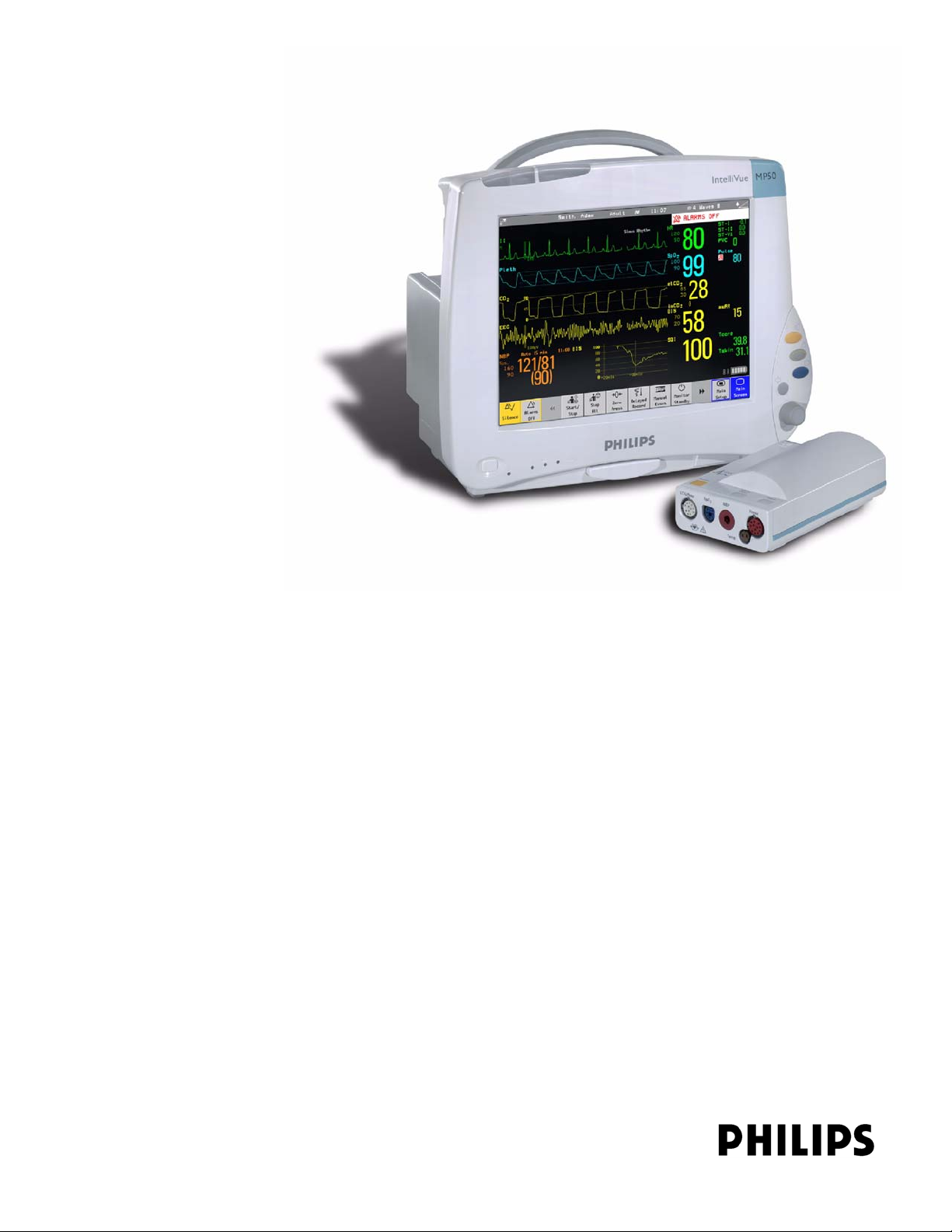
IntelliVue Patient Monitor
MP2/5/20/30/40/50/60/70/80/90
MP5T/X2
For monitor release G.0 with software revision G.0x.xx
Patient Monitoring
Page 2

Philips Medizin Systeme Boeblingen GmbH
Hewlett-Packard Str. 2
71034 Boeblingen
Germany
© Copyright 2002-2008
Koninklijke Philips Electronics N.V.
All Rights Reserved
Part Number M8000-9306M
Reorder Number: 4535 641 12621
Printed in Germany 10/08
Page 3

1Table Of Contents
1 Understanding Configuration 1
Who is this Guide for? 1
Which Monitor Models is this Guide for? 1
What is Configuration Mode? 2
Who Can Change the Monitor Configuration? 2
Understanding Profiles and Settings 3
Entering and Leaving Configuration Mode 6
About the IntelliVue Support Tool 6
2 Configuring Profiles and Settings Blocks 9
Getting Started 9
Modifying an Existing Profile 10
Modifying an Existing Settings Block 11
Creating New Profiles 11
Deleting a Settings Block or Profile 13
Renaming a Settings Block or Profile 13
Changing the Monitor’s Default Profile 13
Unlocking a Settings Block or Profile 13
Configuring a Second / Third Main Display 14
3 Configuring Screens 17
Understanding Screen Settings 17
Modifying an Existing Screen 18
Creating New Screens 18
Configuring Screens on an XDS Remote Display 18
Changing the Content of Screen Elements 19
Changing the Size and Position of Screen Elements 21
Configuring SmartKeys 21
Configuring Special Screen Settings 22
4 Configuration Settings Appendix 25
About Configuration Settings 25
Profile Settings 28
Measurement Settings 29
Monitor Settings 84
Unique Monitor Settings 118
Global Settings 147
Hardware Settings 176
Monitor Database Configuration 184
H Option-Specific Settings 187
Release-Specific Information 188
1
Page 4

5 Screen & Profile Overview 191
About the Screen Configurations 191
Sample Screen Image (.bmp) 193
MP60/MP70/MP80/MP90 Configuration Overview 194
MP40/MP50 Configuration Overview 198
MP20/MP30 Configuration Overview 202
MP20 Junior & MP20L Configuration Overview 206
MP5 Configuration Overview 208
MP5T Configuration Overview 213
MP2/X2 Configuration Overview 214
Screen Overview 215
MP60/MP70/MP80/MP90 Screen Overview 216
MP40/MP50 Screen Overview 225
MP20/MP30 Screen Overview 230
MP20 Junior (M20) & MP20L (M21) Screen Overview 235
MP5 Screen Overview 236
MP5 Options B10/B11/B14 Screen Overview 241
MP5T Screen Overview 242
MP2 Screen Overview 243
X2 Screen Overview 244
2
Page 5

1Understanding Configuration
Who is this Guide for?
This book is for anyone making permanent changes to the configuration of an IntelliVue Patient
Monitor. You must understand English, be familiar with the monitor and its Instructions for Use,
know how to make changes to measurements and settings in monitoring mode, and understand the
clinical implications of any changes you make.
WARNING Before starting monitoring, check that the configuration meets your requirements, especially patient
category, alarm limits and paced setting.
WARNING Changing the configuration may alter the way the monitor performs when monitoring patients. Do
not change anything unless you are aware of the possible consequences, especially if you are monitoring
a patient whilst in configuration mode.
1
Which Monitor Models is this Guide for?
The descriptions and configuration settings in this configuration guide are valid for IntelliVue Patient
Monitors MP2, MP5, MP20/30, MP40/50, MP60/70, MP80/90, and the IntelliVue X2 MultiMeasurement Module (when used as a standalone monitor), release G.0 with software G.0x.xx. This
guide can not be used for other monitor models or IntelliVue monitors with other software releases.
Not all information contained in this guide applies to all monitor models. If a certain section applies
only to certain models, this is indicated next to the section heading.
For example, if a certain section does not apply to the MP2 and X2, or - in other words - only applies
to monitor models MP5, MP20/30, MP40/50, MP60/70, and MP80/90, it would be indicated like
this:
MP5-90
<Section Heading>
only
1
Page 6
1 Understanding Configuration What is Configuration Mode?
What is Configuration Mode?
The monitor ships with preset configurations that are suitable for common monitoring situations. To
develop and store your own configurations you must switch to the monitors configuration mode.
Configuration mode is a password-protected operating mode that lets expert users make permanent
changes to the monitor configuration. It is an extension of monitoring mode; it contains all of the settings
available in monitoring mode plus some settings that are accessible only in configuration mode.
For example, when you access the Setup SpO
menu in
2
monitoring mode, you will only be able to see and
change these settings.
In configuration mode, these additional settings become
visible.
Setup SpO
High Limit : 100
Low Limit : 90
Desat Limit : 80
Alarms : On
SpO2 : On
Pulse (Sp02)
Label : SpO
Set Perf Ref.
QRS Volume : 1
Tone Modulation : Yes
Tone Mod. Type : Enhanced
Perfusion : On
Average : 10 sec
High Alarm Delay : 10 sec
Low Alarm Delay : 10 sec
Desat Delay : 20 sec
NBP Alarm Suppr. : On
Extd. Auto OnOff : Disabled
Color : Cyan
2
2
In monitoring mode, you can change settings, but cannot permanently store the changes to the monitor
configuration.In configuration mode, you can change and permanently store settings to the monitor
configuration.
Who Can Change the Monitor Configuration?
Only people authorized to do so by their institution should make changes in configuration mode. They
require the configuration mode password.
2
Page 7

Understanding Profiles and Settings 1 Understanding Configuration
Understanding Profiles and Settings
The IntelliVue patient monitor is highly configurable. To manage its various settings, settings are grouped
into six main categories:
•Profiles
•Screens
•Monitor settings
• Measurement settings
• Global settings
• Hardware settings
All settings except hardware settings can be changed in configuration mode. Hardware settings can be
changed in service mode only (with some exceptions).
Profiles
Profiles are named combinations of the following “building blocks”:
• Patient category
•Paced status
•(Display) Screen
• Measurement Settings block
• Monitor Settings block.
A monitor can have up to 20 different Profiles.
When you load a Profile, the configured combination
of building blocks becomes active.
This provides a powerful method to easily adapt the
monitor to specific clinical scenarios or users, or
switch back and forth between different configurations depending on specific phases within a case.
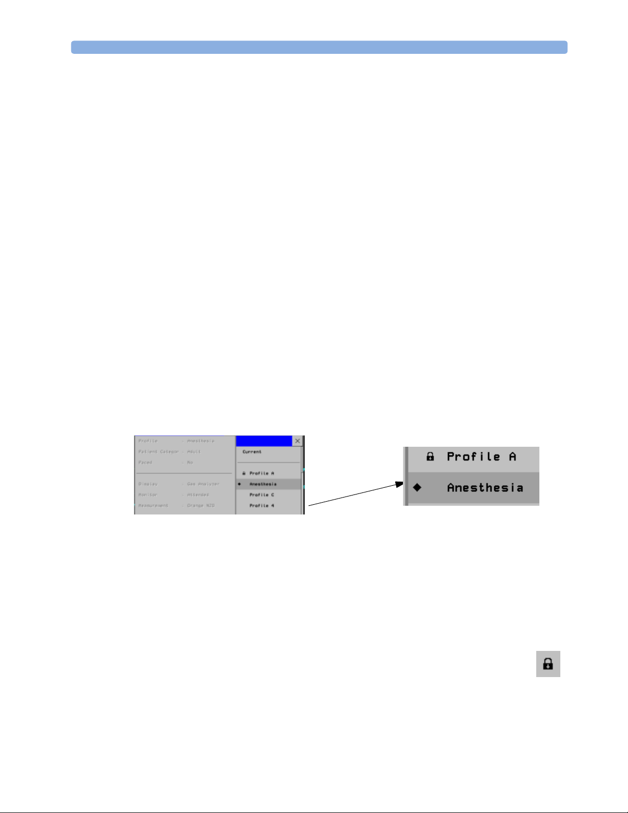
Profile : Profile Adult
Patient Category : Adult
Paced : Yes
Display : 6 Waves A
Measmnt. Settings : Measmt. Adult
Monitor Settings : Monitor A
Profiles
Consider this example: You are in the ER. Your monitor is configured for an adult patient. Your next
patient is a 5-year old child. By switching to a predefined pediatric ER Profile, you can have appropriate
measurement settings (such as alarm limits), patient category and so forth very easily, instead of having to
alter measurements and limits individually. In this example, your monitor’s Profiles can be based on the
age and condition of your patient, but there are of course other use models.
3
Page 8
1 Understanding Configuration Understanding Profiles and Settings
This graphic illustrates the concept of Profiles and their building blocks in the IntelliVue Patient Monitor.
Notice that settings blocks and screens are only linked to a Profile. This indicates that storing a changed
Profile saves the combination of building blocks, but not individual monitor settings, measurement
settings, or Screens. Changes that you have made to measurement or monitor settings, or screens can only
be stored in the appropriate type of settings block or Screen. For details, see "Modifying an Existing
Settings Block" on page 11.
Patient Category
For each profile, a patient category is defined. This patient category becomes active when you load the
Profile. It determines
– the algorithm the monitor uses to process and calculate some measurements (for example
arrhythmia),
– the safety limits that apply for some measurements (for example NBP), and
– the alarm limit ranges for all measurements.
Note that a change of the patient category does not change any alarm limits to fit this category.
Paced
For each profile, the paced status is defined. The defined paced status becomes active when you load the
Profile. The paced setting determines whether the monitor shows pacemaker pulses or not. When Paced
is set to No, pace pulses are filtered and therefore do not show in the ECG wave. For paced patients,
Paced must be set to Yes.
4
Page 9

Understanding Profiles and Settings 1 Understanding Configuration
Display Screens
A Screen defines the overall selection, size and position of measurement waves, numerics and SmartKeys
on the monitor display. A monitor can have a maximum of 20 preconfigured Screens, optimized for
common monitoring scenarios. Examples of different Screens include the Big Numerics, the 12-
lead ECG, and the Horizon Screen. For a complete list of Screens supplied with your monitor model,
see the section "Screen Overview" on page 215.
For each Profile, a Screen is defined. This Screen becomes the active Screen when you load the Profile. If
you are using two or three main displays, for each main display a different Screen can be configured.
Measurement Settings
Measurement settings are settings specific to each measurement, for example alarm limits, measurement
color, or measurement unit. For a complete list of measurement settings, see the section "Measurement
Settings" on page 29.
A monitor can have a maximum of 10 blocks of measurement settings. Each block includes the complete
list of measurement settings available. You can configure individual measurement settings differently for
each settings block. By configuring different settings blocks, you can provide customized combinations of
measurement settings for different profiles.
A typical example are the measurement settings blocks provided in the factory default configurations
(documented in this guide). The measurement settings blocks Measmt. Adult, and Measmt.
Pedi, for example, differ mainly by the alarm limits which are configured differently for different patient
ages. When you switch to a different Profile, for example from Profile Adult to Profile Pedi,
the measurement settings block defined for that Profile becomes active.
Monitor Settings
Monitor settings define general aspects of how the monitor works, and include settings that affect more
than one measurement, such as alarm volume, report settings, or display brightness. For a complete list of
monitor settings, see the section "Monitor Settings" on page 84.
A monitor can have a maximum of 10 blocks of monitor settings. Each block includes the complete list of
monitor settings available. You can configure individual monitor settings differently for each settings
block. By configuring different settings blocks, you can provide customized combinations of monitor
settings for different profiles.
For example, you could generate a monitor settings block, in which the monitor’s display brightness is
lowered and the alarm volume is softened, and call it “Night”. When you then assign this block to a new
Profile and name it accordingly, for example “Profile Night”, you can easily switch between day and night
settings.
Global Settings
Global settings are typically set once at monitor installation by service personnel and include settings such
as Altitude, Line Frequency, or Label Set. Global settings are not part of a Profile. They can
be changed in configuration mode only and are automatically stored in the monitor’s configuration with
each change. For a complete list of Global Settings, see the section "Global Settings" on page 147.
Hardware Settings
Most hardware settings can only be changed in service mode. They are typically set once at monitor
installation by service personnel, and include settings, such as Keyboard layout, the configuration of the
monitor interfaces, or video settings, such as Display Type, Display Size, and Display
5
Page 10

1 Understanding Configuration Entering and Leaving Configuration Mode
Resolution. Like global settings, hardware settings are independent of Profiles, and any changes you
make to the hardware settings configuration are automatically stored, there is no need to save them in an
extra step. For a complete list of Hardware Settings, see the section "Hardware Settings" on page 176, or
refer to the Service Guide of your monitor model, provided on the Documentation DVD supplied with
your monitor.
Entering and Leaving Configuration Mode
Switching between monitoring and configuration mode does not affect the active settings. You can even
continue to monitor patients while in configuration mode. The password for configuration mode is given
in the monitor’s service documentation.
To enter configuration mode:
1 In the Main Setup menu, select Operating Modes.
2 Select Config and enter the password.
The monitor displays Config at the right hand side of the status line and in the center of the Screen
while you are in configuration mode.
Before you leave configuration mode, always be sure to store any changes you made. You must store
changes made to each Settings Block and to each Profile, individually. As it may be difficult to remember
whether the settings you changed belong to a Monitor Settings block or a Measurement Settings block, we
recommend that you store each block before you leave configuration mode.
WARNING If you are handing over the monitor to the end-users directly after configuration, make sure that it is in
Monitoring mode.
To leave configuration mode either:
♦ In the Main Setup menu, select Operating Modes and then select the operating mode you
require or
♦ Switch the monitor off, then switch it on again.
– If you switch the monitor off and then on again after less than one minute, it returns in monitoring
mode with the same settings (“hotstart”).
– If you leave the monitor switched off for more than one minute, the Profiles and settings loaded
when you switch back on are determined by the Automat. Default setting. See “Global
Settings” on page 147.
About the IntelliVue Support Tool
The IntelliVue Support Tool is a PC-based software application that is designed to help configuring
IntelliVue monitors and to manage IntelliVue Monitor configurations.
Using the Support Tool, you can, for example, read in (clone) a configuration from an IntelliVue monitor
to a PC, modify this configuration offline on the PC, and then store (clone) the changed version back to
the monitor. With the Support Tool you can clone configurations to more than one monitor at a time.
You can also use the Support Tool to make backups of your configurations, or generate configuration
reports. The configuration files generated by the Support Tool are stored in a format that can be e-mailed.
6
Page 11

About the IntelliVue Support Tool 1 Understanding Configuration
What Can I Configure with the Support Tool?
You can configure everything you can configure on the monitor, except that you cannot change individual
monitor and measurement settings.
In addition to the configuration on the monitor, the Support Tool allows, for example:
• Changing the order of items in the lists of Screens, measurement or monitor settings blocks.
• Unlocking Profiles, Screens and settings blocks.
• Making realtime waves, or screen trends overlap on the Screen.
• Importing Screens into a configuration, and copying Screens between configurations.
• Importing SmartKey configurations into a configuration.
• Copying monitor settings, measurement settings, and global settings between config files.
• Importing, creating and modifying drug calculator configurations.
For a complete description of the Support Tool functionality, refer to the Support Tool Instructions for
Use, provided with the Support Tool.
How Can I Get a Support Tool License Key?
To use the Support Tool, you must have a license key. To get a license key, you must complete a special
training. Please contact your local Philips Customer Response Center for further details.
The Support Tool functionality your license key permits you to use, depends on your function (e.g.
Biomed / CE / Configuration Expert) and your level of training.
License keys are issued to individuals and they may not be shared. The Support Tool tracks the use of each
license key: you will be held responsible for any configuration changes made using your license key.
7
Page 12

1 Understanding Configuration About the IntelliVue Support Tool
8
Page 13

2Configuring Profiles and
Getting Started
To start configuring your monitor, access Profiles by selecting either:
•the Profiles screen element from the monitor’s Info Line, or
• the Profiles SmartKey , or
• Profiles from the Main Setup menu.
The configuration pop-up keys will appear to let you carry out configuration tasks.
2
Settings Blocks
Using the Configuration Pop-up Keys
In configuration mode, the pop-up keys allow you to:
activate a Profile or settings
block
save active settings into the selected
settings block, or settings blocks
into the selected Profile.
Select the Confirm pop-up key to apply your changes.
create a new Profile or
settings block based on the
current one
delete the selected
Profile or settings block
rename the selected
Profile or settings block
make the current Profile
the default Profile
9
Page 14
2 Configuring Profiles and Settings Blocks Modifying an Existing Profile
Modifying an Existing Profile
You can change the settings within an existing Profile. The monitor remembers any changes made when
you switch between monitoring mode and configuration mode. All changes can be permanently stored in
configuration mode, as described in the following sections.
Be aware that if you don’t store changes they will be reset to the monitor’s stored configuration when you
• change from configuration or monitoring mode to service or demonstration mode,
• load Profiles or Settings Blocks, or
• switch off the monitor for more than one minute (if the Global Setting Automat. Default is set
to Yes).
Changing the Combination of Settings Blocks in an Existing Profile
To permanently save a different combination of settings blocks into an existing Profile:
1 Select the Profile you want to change and select the Load pop-up key to activate it.
2 Change the patient category and paced status if necessary.
3 Load the settings blocks you want to have into the activated Profile one after the other by selecting
them in the Profiles menu and then selecting the Load pop-up key. These settings become active
immediately in the monitor, but the asterisk beside the Profile name in the Profiles menu shows that
the newly loaded blocks are not yet stored as part of the Profile.
4 Select the Profile again.
5 Select the Store pop-up key.
This example shows the changing of a Profile. The existing Profile 1 was built from a combination of
Screen A + Monitor Settings Block A + Measurement Settings Block A.
The new Profile 2 is built from a combination of Screen B + Monitor Settings Block D + Measurement
Settings Block C. This is now the active Profile, because it is loaded into the monitor’s active memory.
Active settings
Display
screens
Monitor
settings
Measurement
settings
load
AB
load
A
load
A
Settings blocks Examples
screens
layout
content
CDE
alarm volume
alarms latching
alarm off time
BC
B
C
D
DE
E
QRS volume
Network setting
ECG alarm limits
ABP alarms on/off
NBP repeat time
Resp trigger mode
10
Existing Profile 1 New Profile 2
Page 15

Modifying an Existing Settings Block 2 Configuring Profiles and Settings Blocks
Modifying an Existing Settings Block
To change settings in an existing settings block:
1 Select the settings block you want to change and select the Load pop-up key to activate it.
2 Make the changes to the individual measurements or monitor settings.
3 Select the Store pop-up key to overwrite the existing settings. Changes to a settings block affect all
Profiles in which this block is used.
Creating New Profiles
Follow these steps to create a new Profile ICU B based on the Profile ICU A and add it to the list of
Profiles stored in the monitor. As creating a Profile requires you to activate different settings, you should
not do this while monitoring a patient. Each new name you assign to Profiles or Settings Blocks must be
unique, otherwise you have two items with the same name and you will not be able to distinguish them.
Existing Profile:
Profiles
Profile : ICU A
Patient Category : Adult
Paced : No
Display : 6 Waves A
Measmnt. Settings : Measmt. A
Monitor Settings : Monitor A
1 Choose a Profile similar to the one you want to create from the list of Profiles available in the monitor.
Profile to be created:
Profiles
Profile : ICU B
Patient Category : Pedi
Paced : No
Display : 6 Waves B
Measmnt. Settings : Measmt. B
Monitor Settings : Monitor B
To preview the combination of settings blocks contained in any Profile, in the Profiles menu,
select that Profile from the list. The Profiles menu (which is grayed-out) changes to indicate the
contents of the selected Profile. To view the settings blocks of the active Profile, select Current.
2 Select Load to activate this Profile.
3 Create a new Profile that references the same settings as the active Profile:
a. In the Profiles menu, select Profile.
b. Select the pop-up key New.
c. Use the on-screen keyboard to type a meaningful name for the new Profile, in this case ICU B. If
you do not name the Profile, the monitor will assign a default name. You can rename the Profile
later.
d. Select Enter.
e. Select Load to activate the new Profile.
4 Create new settings blocks for the new Profile.
a. In the Profiles menu, select Monitor Settings.
11
Page 16

2 Configuring Profiles and Settings Blocks Creating New Profiles
b. Select the pop-up key New.
c. Use the on-screen keyboard to type the name of the new settings block, in this case Monitor B.
If you do not name the Settings Block, the monitor will assign a default name. You can rename the
Settings Block later.
d. Select Enter. You have now created a new settings block containing the same monitor settings as
the block Monitor A.
e. Repeat this procedure to create a new measurement settings block.
You have now prepared the structure of the Profile you are creating.
5 Select the required Patient Category for the new Profile. In the Profiles menu, select either
Adult, Pedi, or Neo, or select As Is
to retain the patient category active at the time this Profile is
activated. Note that if you configure Patient Category in the default Profile to As Is, the
monitor starts after a coldstart with Patient Category set to Neo. A coldstart will be caused,
for example, after changing the monitor’s database configuration, see "Monitor Database
Configuration" on page 184.
6 Select the required Paced mode for the new Profile. In the Profiles menu, select Yes for paced
patients, No for non-paced patients, or
As Is to retain the paced status active at the time this Profile
is activated. Note that if you configure Paced in the default Profile to As Is, the monitor starts
after a coldstart with Paced set to Yes. A coldstart will be caused, for example, after changing the
monitor’s database configuration, see "Monitor Database Configuration" on page 184.
7 Select a Screen for the new Profile.
a. In the Profiles menu, select Display
b. Select the Screen you require from the pop-up list of available Screens.
c. Select Load to confirm your choice.
d. If the monitor has more than one main display, repeat these steps for the additional displays.
NOTE If you are using an XDS Remote Display as second or third main display, the default Screen for this
display must be configured in the XDS Application software. It cannot be stored as part of the Profile
configuration of the IntelliVue monitor. For more detail, refer to the Installation and Configuration
Guide for the XDS Application.
8 Adjust monitor and measurement settings as required.
9 Store the changed settings to the settings blocks. In the Profiles menu, select
Measmnt. Settings, and then select Store and then Confirm to apply your changes.
Repeat this for Monitor Settings. There is no undo function.
10 Store the finished Profile. In the Profiles menu, select Profile and then select Store and
then Confirm to apply your changes. There is no undo function.
CAUTION When changing settings, you are strongly advised to create new settings blocks, rather than storing changes
to the existing ones. Similarly, when changing a Profile, you are strongly advised to create a new Profile,
rather than storing changes to an existing one. Once you store changes to a settings block or Profile, there
is no way to undo these changes, unless you have saved a backup using the Support Tool. Settings blocks
may be used in more than one Profile. If you edit a settings block it will change in the other Profiles in
which it is used.
12
Page 17
Deleting a Settings Block or Profile 2 Configuring Profiles and Settings Blocks
Deleting a Settings Block or Profile
You cannot delete a locked settings block, or one that is used in any Profile. You must remove it from the
Profile or delete the Profile first.
1 From the Profiles menu, select the block or Profile you want to delete.
2 Select the Delete pop-up key.
Renaming a Settings Block or Profile
If you rename a settings block that is used in other Profiles, the name changes in the other Profiles too.
1 From the Profiles menu, select the block or Profile you want to rename.
2 Select Rename.
3 Use the on-screen keyboard to type the new name, then select Enter to apply the change.
Changing the Monitor’s Default Profile
Every monitor has one default Profile. This is marked with a black diamond.The monitor loads the default
Profile:
• when returning to monitoring mode after leaving demonstration Mode (but not after leaving
configuration or service mode).
• after discharging a patient.
• after being switched off for more than 60 seconds (only if Automat. Default is set to Yes).
To change the default Profile:
1 In the Profiles menu, select the Profile you want to set as default.
2 From the pop-up keys select Set Default. The “default diamond” jumps to this Profile to indicate
that it is now this monitor’s default Profile. This setting takes effect immediately, you do not have to
switch the monitor off and on again.
Unlocking a Settings Block or Profile
Profiles and settings blocks can be locked to prevent them from being modified or deleted. This
ensures that a minimum configuration is always available. A locked Profile or settings block is
identified (in configuration mode only) by a lock symbol.
You cannot unlock Profiles or settings blocks in the monitor’s configuration mode. To lock or
unlock Profiles or settings blocks you need to use the IntelliVue Support Tool.
13
Page 18
2 Configuring Profiles and Settings Blocks Configuring a Second / Third Main Display
Configuring a Second / Third Main Display
To distinguish between individual main displays, the displays are numbered on the Screen. The number is
shown next to the Screen Name field.
A second main display can be used with
• an MP90 with a Dual CPU, or
• an MP2/X2, MP5, MP60/70, MP80, or MP90 with a single CPU, when using an XDS Remote
Display as the third display.
Display 1 is always the built-in display or the display connected to the first CPU of the Dual CPU
MP90 monitor. Display 2 is the display connected to second CPU of the Dual CPU MP90 monitor
or the XDS Remote Display.
Profiles
Profile : ICU B
Patient Category : Adult
Paced : Yes
Display 1 : 6 Waves B
Display 2 : 12 Lead ECG
Measmnt. Settings : Measmt. B
Monitor Settings : Monitor B
A third main display can be used with
• a D80 Intelligent Display connected to a Dual CPU MP90 monitor, or
• an MP90 with a Dual CPU, when using an XDS Remote Display as the third display.
Display 1 is always the display connected to the first CPU of the MP90 monitor. Display 2 is the
display connected to second CPU, and Display 3 is the display connected to either the D80 or the
XDS Remote Display.
14
Page 19

Configuring a Second / Third Main Display 2 Configuring Profiles and Settings Blocks
Profiles
Profile : ICU B
Patient Category : Adult
Paced : Yes
Display 1 : 6 Waves B
Display 2 : 12 Lead ECG
Display 3 : Big Numerics
Measmnt. Settings : Measmt. B
Monitor Settings : Monitor B
Loading a Screen on a Second / Third Display
To load a Screen onto the second or third main display,
• on the second/third display, enter the Change Screen menu and select a Screen from the list of
available Screens, or
• on any display, enter the Profiles menu, select Display 2 (or Display 3) and select a Screen
from the list of available Screens (not possible on the main display of MP2 and X2 monitors).
NOTE If you are using an IntelliVue monitor with the XDS Remote Display as either the second or third display,
the selection of Screens available for the XDS Remote Display can be different from the Screen selection
for the other displays.
Changing Elements on a Second / Third Display
To change elements on the second or third main display:
1 Load the Screen that you want to modify onto the second/third display.
2 Make the required changes to the Screen.
3 Store the Screen. To do this, enter the monitor’s configuration mode, select Profiles ->
Display 2 (or Display 3), then select the Store pop-up key.
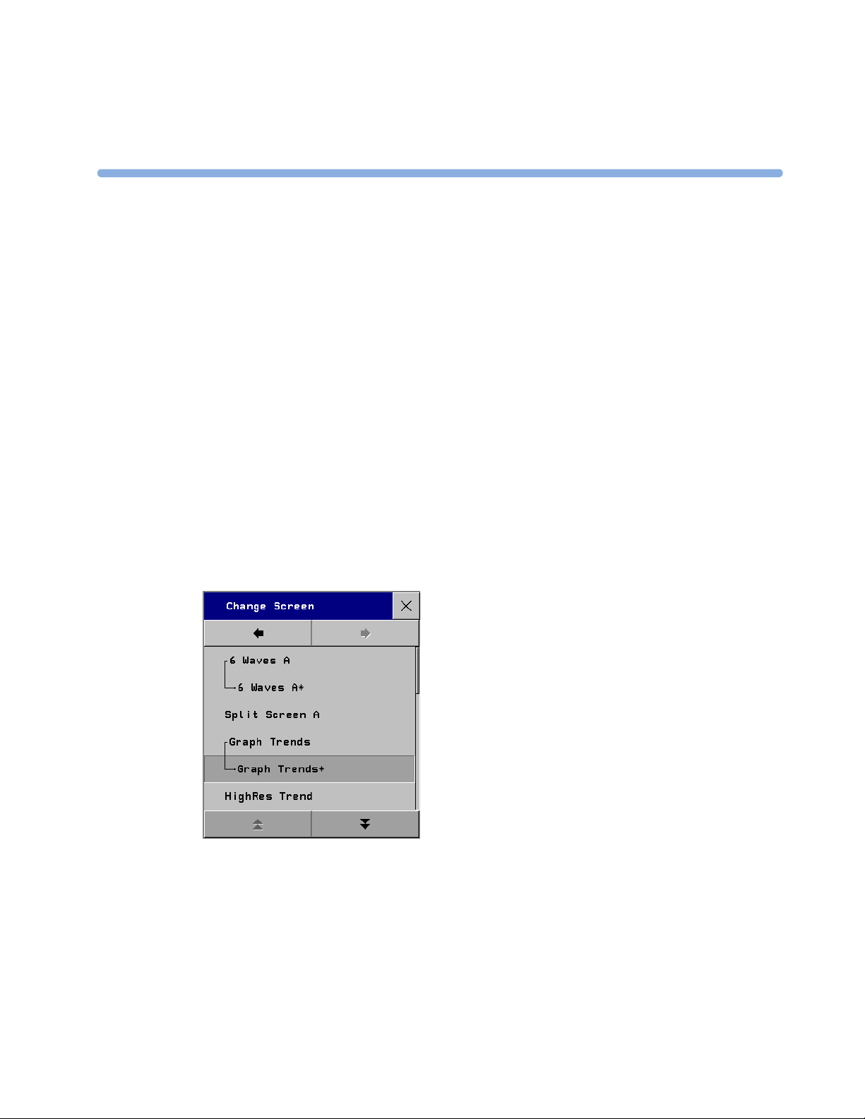
NOTE Any change to a Screen will mark that Screen modified. In the Change Screen menu, the modified
Screen is shown linked to the original Screen and marked with an asterisk (*).
If you load the same Screen onto more than one display, then modify them differently, and then store one
of the Screens, the modified Screen on the other displays will still be available. The stored Screen will be
available on all displays except on the XDS Remote Display.
Changes made to a Screen viewed on an XDS Remote Display will be stored on the PC connected to the
XDS Remote Display and will not be part of the monitor configuration, see "Configuring Screens on an
XDS Remote Display" on page 18.
15
Page 20

2 Configuring Profiles and Settings Blocks Configuring a Second / Third Main Display
16
Page 21
3Configuring Screens
During monitoring, you can change the content of most of the Screen elements, for example you can
exchange a Resp wave for a Pressure wave. These changes can be permanently stored as part of the
Screen settings in configuration mode.
You can also use the IntelliVue Support Tool to configure Screens offline on a personal computer and
then upload them as part of a configuration file to one or more patient monitors. To use the IntelliVue
Support Tool for Screen configuration, you must have a support tool and a support tool license key
that entitles you to use the Screen configuration functionality. See "About the IntelliVue Support
Tool" on page 6 and the Support Tool Instructions for Use.
Understanding Screen Settings
Screen settings are stored in the Screen. Changing a Screen setting modifies the Screen. This is
indicated by an asterisk (*) in front of the Screen name. In the Change Screen menu, modified Screens
are shown linked to their parent Screens.
3
Screen settings include:
• the basic layout of a Screen, i.e. the selection, size, and position of any Screen element visible on the
Screen. The Screen layout cannot be modified in the monitor’s configuration mode.
• the content of each Screen element, i.e. the information displayed in each Screen element.
• the selection and sequence of SmartKeys available on a Screen.
• special settings that determine the behavior of certain Screen elements, such as Screen trends,
realtime waves, embedded trend windows, or embedded Other Bed Overview windows.
17
Page 22

3 Configuring Screens Modifying an Existing Screen
Modifying an Existing Screen
To change an existing Screen:
1 Load the Screen and make the changes to the Screen.
2 In configuration mode, select Profiles -> Display (or Display 2, or Display 3).
3 In the list of Screens, the modified Screen is shown linked to the original Screen and marked with an
asterisk (*). Select the Store pop-up key to overwrite the existing Screen. Changes to the Screen
affect all Profiles in which this Screen is used.
NOTE Changes made to a Screen viewed on an XDS Remote Display will be stored on the PC connected to the
XDS Remote Display and will not be part of the monitor configuration, see "Configuring Screens on an
XDS Remote Display" on page 18.
Creating New Screens
1 Load a Screen similar to the one you want to create from the list of Screens available in the monitor.
2 Create a new Screen based on the active Screen:
a. In the Profiles menu, select Display (or Display 2, or Display 3).
b. Select the pop-up key New.
c. Use the on-screen keyboard to type a meaningful name for the new Screen. If you do not name the
Screen, the monitor will assign a default name. You can rename it later.
d. Select Enter.
3 Change the content of the Screen as required.
4 Store the finished Screen:
a. In the Profiles menu, select Display (or Display 2, or Display 3).
b. Select the pop-up key Store and then Confirm to apply your changes. There is no undo
function.
NOTE Changes made to a Screen viewed on an XDS Remote Display will be stored on the PC connected to the
XDS Remote Display and will not be part of the monitor configuration, see "Configuring Screens on an
XDS Remote Display" on page 18.
Configuring Screens on an XDS Remote Display
For certain IntelliVue monitor models, the XDS Remote Display (IntelliVue XDS solution) can be used as
second or third main display.
18
When you make changes to a Screen that is viewed on an XDS Remote Display, be aware of the following
implications:
• The changes are stored on the XDS Remote Display and not on the monitor.
• The changed Screen is not part of the monitor configuration and can therefore not be cloned to another
monitor using the IntelliVue Support Tool.
• The changed Screen can be modified with the Screen Editor of the IntelliVue Support Tool.
Page 23

Changing the Content of Screen Elements 3 Configuring Screens
For more details regarding the configuration of the XDS Remote Display, refer to the Installation and
Configuration Guide for the XDS Application.
Changing the Content of Screen Elements
Changing the Content of a Wave Element
To change the content of a wave element on a Screen,
1 Select the wave you want to change.
2 From the wave menu that appears, select Change Wave and then select the wave you want to be
displayed.
Changing the Content of a Numeric Element
To change the content of a numeric element on a Screen,
1 Select the numeric you want to change. You can only change numerics that are not directly associated
with (aligned to) a wave.
2 From the Setup menu that appears, select Change Numeric and then select the numeric you want
to be displayed.
Changing the Content of a Screen Trend Element
To change the content of a screen trend element on a Screen,
1 Select the screen trend you want to change.
2 From the trend menu that appears, select Change Trend and then select the screen trend you want
to be displayed.
Changing the Content of a High Resolution Trend Element
MP5-90
To change the content of a HiRes Trend element on a Screen,
only
1 Select the HiRes Trend you want to change.
2 From the menu that appears, select the HiRes trend you want to be displayed.
Depending on the H option (see "Understanding H and M Options" on page 27) and C option of your
monitor, the following parameters are available for selection:
H10 / H40 H20 H30 Comments
btbHR X X X These 4 parameters are included in the OxyCRG option
Any SpO2 XXX
Resp XXX
tcpO
2
X
(C08)
MP5: tcpO
not available.
2
19
Page 24

3 Configuring Screens Changing the Content of Screen Elements
H10 / H40 H20 H30 Comments
Pulse X X X MP20 -90 monitors only
Any Perf XXX
tcpCO
2
CO
2
ABP XXX
PAP XX
CVP XXX
ICP XXX
CPP XXX
BIS XXX
CCO XXX
AWP XXX
Any Agent X
Delta SpO2 X
inO
2
XX
XXX
XX
Displaying Timers on the Main Screen
MP5-90
If you want to have a timer displayed on the Main Screen, you can substitute it for a numeric which is not
directly associated with a wave.
only
To display a timer on the Main Screen,
1 Select the numeric you want to substitute.
2 Select Change Numeric.
3 Select Any Timer. The monitor automatically uses the timer label with the highest priority that is
not displayed on the Screen yet. See "Configuring Timers" on page 139.
Be aware of the following restrictions:
• If limited space is available, some elements displayed in the Timers window may not be displayed. The
minimum information displayed is the elapsed or remaining time.
• The maximum number of timers that can be displayed on the Main Screen depends on your monitor
model:
– MP60-90: four timers
– MP40-50: three timers
– MP20-30: two timers
– MP5/MP5T: one timer
–MP2/X2: no timer
• Any timer label can only be used once per Screen.
Displaying a Clock on the Main Screen
MP5-90
20
If you want to have a clock displayed on the Main Screen, you can substitute it for a numeric which is not
directly associated with a wave.
only
To display a clock on the Main Screen,
Page 25

Changing the Size and Position of Screen Elements 3 Configuring Screens
Select the numeric you want to substitute.
1
2 Select Change Numeric.
3 Select Clock.
Be aware of the following restrictions:
• Only one clock can be displayed per Screen
• If limited space is available, the label “Clock” may not be displayed. The minimum information
displayed is the time.
Displaying a ProtocolWatch Status Indicator on the Main Screen
MP5-90
If you want to have a ProtocolWatch status indicator displayed on the Main Screen, you can substitute it
for a numeric which is not directly associated with a wave.
only
To display a ProtocolWatch status indicator on the Main Screen,
1 Select the numeric you want to substitute.
2 Select Change Numeric.
3 Select PW Status.
Only one ProtocolWatch status indicator can be displayed per Screen.
Changing the Size and Position of Screen Elements
You cannot change the size and position of Screen elements. This is a configuration service that is
provided, at a charge, by Philips, for monitors with option C20.
Configuring SmartKeys
There are two ways to configure SmartKeys:
• Configuring a different list of SmartKeys for each Screen (not possible for MP2/X2)
• Configuring a global list of SmartKeys that applies for all Screens
Configuring a Different List of SmartKeys for Each Screen
MP5-90
The selection and order of SmartKeys that are specific to a Screen are stored as part of the Screen, i.e. as a
Screen setting. This can be configured on the monitor (in configuration mode) or by using the Support
only
Tool Screen Editor. The following describes how to configure SmartKeys on the monitor. For a detailed
description on how to use the Support Tool Screen Editor, see the Support Tool Instructions for Use.
To change the selection of SmartKeys displayed,
1 Select Main Screen, then select the left double arrow key to scroll back one page of SmartKeys.
2 Select the SmartKey SmartKeys to open a menu that lists all SmartKeys currently configured for
that Screen. From the pop-up key line, select Add to open a second menu that contains all available
SmartKeys.
3 From the second menu, select the desired SmartKey. This adds the new key to the bottom of the list of
configured SmartKeys (on the left). The maximum number of SmartKeys per Screen is 30 for the
MP60/70/80/90, and 24 for the MP40/50, MP20/30, and MP5.
21
Page 26

3 Configuring Screens Configuring Special Screen Settings
To delete a SmartKey from the list of configured SmartKeys,
♦ select it in the list, then select the pop-up key Delete.
To move a SmartKey to a different position,
♦ Use the Sort Up and Sort Down pop-up keys. The number of SmartKeys visible at a time
depends on the monitor’s display resolution:
SVGA: 6
XGA: 7
SXGA: 9
WXGA: 9
WXGA+: 10
WSXGA: 11
Configuring a Global List of SmartKeys for All Screens
The global list of SmartKeys is stored as a unique monitor setting in the monitor configuration. See the
section "Configuring User Interface Settings - Keys" on page 143 for details on how to configure the
global SmartKey list.
Individual SmartKey configurations for each Screen override the global SmartKey configuration. The
global SmartKey list will therefore only be visible when you load a Screen that has no SmartKeys
configured to it.
If you want to use the global SmartKeys for all Screens on a monitor, you must delete all individual
SmartKeys from all Screens in the configuration.
Configuring Special Screen Settings
Configuring the Wave Channel Speed
To change this setting, select the measurement wave on the Screen to open the related Wave menu.
Change Speed This setting determines the wave speed of the related wave channel.
If set to Global, the speed of the wave channel follows the monitor setting Global Speed (or
RespiratorySpeed, or EEG Speed) as described under "Configuring User Interface Settings" on
page 110.
If set to any of the fixed speeds (6.25, 12.5, 25, 50 mm/sec), the speed of that wave channel follows
its own distinct setting and is not affected by any changes of the Global Speed. The wave channel
speed is independent of the wave (label) depicted in the channel. If you change the wave, the new wave
will retain the set channel speed.
Configuring Screen Trends
To change the following settings, select the screen trend on the Screen to open the related Trend menu.
Change TrendTime This setting determines in a screen trend. If set to Global, the trend time in
the screen trend channel follows the monitor setting Screen Trend Time as described under
"Configuring Screen Trend Settings" on page 91. If set to any of the fixed times (30min, 1h, 2h, 4h,
8h, 12h), the screen trend time follows its own distinct time setting and is not affected by any changes of
the global Screen Trend Time.
22
Page 27

Configuring Special Screen Settings 3 Configuring Screens
Change View The screen trend presentation can be configured to Tabular, Graphical,
Horizon, or Histogram. The Tabular view can only be used with aperiodic measurements, such as
NBP, C.O., C.I., PAWP. If you configure the view of an NBP trend, for example, to Tabular, and
during monitoring the user changes the trend to a periodic measurement, such as ABP, the view
automatically switches to Graphical.
ShowHorizon Trend The horizon view is made up of 4 elements:
1 a horizon, drawn in white, as a reference baseline to help you visualize changes in the patient’s
condition.
2 a graphical trend, displaying patient data for the set TrendTime.
3 a trend indicator arrow, indicating how the patient trend has developed in the last ten minutes.
4 a deviation bar, showing how the currently measured value deviates from the stored baseline.
If you set ShowHorizon Trend to Yes, all 4 elements of the horizon view are shown. If you set it to
No, the graphical trend information (2) is not displayed in the trend channel.
Configuring an Embedded Trend Window
To change the following settings, select the embedded Trend window on the Screen to open the related
pop-up key line. Note that the following settings are Screen settings and therefore do not affect the
behavior of the normal (not embedded) Vital Signs and Graph Trend windows.
Select Interval This setting defines the trend interval that will be used in the embedded trend
window when the corresponding Screen (with the embedded trend window) is opened.
Graph Trend / Vital Signs This setting defines the view (Graphical Trends or Vital Signs
table) of the embedded trend window when the corresponding Screen is opened. The view can be changed
at any time.
Select Group This setting defines the trend group that is displayed in the embedded trend window
when the corresponding Screen is opened.
The following setting applies for embedded Graph Trend windows only. To change the setting, select the
embedded Graph Trend window on the Screen, then select one of the segments on the left side of the
window to open the segment menu.
No. of Segments This setting defines the number of trend segments displayed in the embedded
Graph Trends window when the Screen is opened.
Configuring an Embedded CSA Window
MP40-90
To change the following settings, select the embedded CSA window on the Screen to open the related
pop-up key line. Note that the following settings are Screen settings and therefore do not affect the
only
behavior of the normal (not embedded) CSA window.
On/Off SEF defines whether the SEF trend line is displayed in the embedded CSA window when the
corresponding Screen is loaded.
On/Off MDF defines whether the MDF trend line is displayed in the embedded CSA window when the
corresponding Screen is loaded.
On/Off PPF defines whether the PPF trend line is displayed in the embedded CSA window when the
corresponding Screen is loaded.
23
Page 28

3 Configuring Screens Configuring Special Screen Settings
Buffer defines which of the three preconfigured buffers is used when the Screen with the embedded
CSA window is loaded.
On/Off Clipping Set Clipping to On to improve the 3-D presentation of the embedded CSA
and make it more “readable”. When set to On, peaks in the spectral lines are artificially clipped at a certain
height (see "CSA Window Configuration Implications" on page 98). If Clipping is Off, peaks can be
displayed over the full window height which may result in a more cluttered presentation.
Clipping
Hidden lines
Frequency Scale defines the bandwidth displayed in the embedded CSA.
Configuring an Embedded Other Bed Window
MP5-90
For Screens with an embedded Other Bed window, you can configure which bed is displayed in the Other
Bed window each time the Screen is loaded.
only
To configure the embedded Other Bed window,
1 select the Other Bed window on the Screen
2 select the pop-up key My Care Group. This opens the Care Group menu where you can choose
between the following settings:
– Bed <xx> (Bed ID)
If you select a specific Bed ID, the monitor displays the associated bed every time the Screen is
loaded. If this bed is unavailable, the message “No data from bed” is shown in the embedded
window.
– Any Bed
Select Any Bed if you want the monitor to display the first bed shown in the care group list. If this
bed is removed from the care group, the new first bed in the care group is automatically displayed.
The setting Any Bed might be unavailable if it has been disabled for this Screen using the Support
To o l .
– Blank (Factory Default)
This is the factory default setting used on the “Other Bed” Screen that is part of the Support Tool
Screen library. If an embedded Other Bed window is configured to Blank, the window is empty
when the Screen is loaded.
24
At any time during monitoring, the user can select the Other Bed window and temporarily change the
current setting.
Page 29

4Configuration Settings
About Configuration Settings
The IntelliVue Patient Monitor is pre-configured with factory default settings when it is shipped. This
section documents the factory default settings and lists the configuration implications that need to be
considered when changing settings from their default.
The configuration implications are only provided in this guide. You must read this document before
you modify monitor configurations.
The settings documented here are valid for IntelliVue Patient Monitors release F.0 with software
F.0x.xx.
4
Appendix
Documenting Monitor Configurations
If you change settings from their default, this document will no longer reflect your configuration.
A Philips representative or trained biomedical engineer can generate a detailed report of the changed
monitor configuration using the IntelliVue Support Tool. Make sure you review the description of this
functionality in the Support Tool Instructions for Use before you interpret the content of this report.
Understanding Configuration Implications
When you permanently change any element of the configuration, you must consider the effect of the
new configuration on both patient and application behavior. For additional information on the
context of the configuration settings, see your monitors Instructions for Use. Always ensure that the
monitor users are aware of the configuration settings.
Using the Configuration Tables
The “breadcrumb trail” at the top of each table indicates which Settings Block the settings are grouped
under. For example, “Measurement Setting: Main Setup -> Measurements ->
ECG” means that the ECG settings in the table below the heading are part of the Measurement Settings
Block. This is also the path you should follow to access the settings in the table: in this example, to
configure ECG settings, in the Main Setup menu, select Measurements and then select ECG.
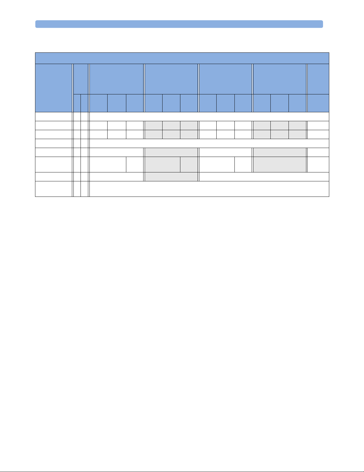
How to read the configuration tables
The following is a (modified) example of a configuration table, as you will find it in the sections of this
manual.
25
Page 30
4 Configuration Settings Appendix About Configuration Settings
Factory Defaults
Item Name Oper.
Alarms from x x Sys.
Sys. High x x 160 120 90
Sys. Low x x 90 70 40
Alarms x x On
Repetition Time x x 15 min
Mode x x Auto Ma-
Done Tone x Off
NBP Time x not applicable, this setting is stored in the Monitor Settings Block: see "Configuring User Interface Settings" on
MP20 - MP90
Mode
(H10/20/40)
C M Profile
Adult
page 110.
Profile
Pedi
Profile
Neo
nual
MP5 - MP90
(H30)
Profile
Adult
180 160
70 90
3 min 10 min 10 min 15 min
On Off
Profile
Pedi
Profile
Neo
MP20 (M20/M21)
MP5 (H10/20/40)
MP2/X2
Profile
Adult
Profile
Pedi
Profile
Neo
MP5T
MP5 (B10/B11/B14)
Profile
Adult
Manual Auto
Profile
Pedi
Profile
Neo
MP2/X2
Profile
Outdoor
Item Name The leftmost column in each table lists the individual configuration items. The names and
order of these items correspond to those of the menu items in the related setup menu in the monitor.
Oper. Mode These two columns indicate in which operating mode the setting is available/visible. If both
columns are marked with an “x”, the setting is available in both modes. If only one column is marked, the
setting is available in the corresponding mode only. Abbreviations used for the operating modes in this
guide are: C for Configuration mode, M for Monitoring mode, S for Service mode.
Monitor Models (Options) This section lists the actual factory default settings for each configuration
item. Some factory default settings may differ between different monitor models or H (application area)
options. If this is the case, this section will be divided into subsections. In the above example, you see the
following subsections:
• MP20 - MP90 with options H10, H20, or H40 (i.e. all except H30),
• MP5 - MP90 with option H30
• MP20 with model option M20 or M21, MP5 with options H10, H20, or H40, and MP2/X2
• MP5T and MP5 with options B10, B11, or B14
• MP2/X2 (Profile Outdoor only)
Some settings are only entered once per table row with the table entry extended to cover all columns. In
our example, you can see this for the settings Alarms from and Alarms. These settings are the same
across all monitor models, options, and profiles and are therefore only entered once in the table, in the
leftmost column.
26
Page 31

About Configuration Settings 4 Configuration Settings Appendix
Profile Adult / Profile Pedi / Profile Neo / Profile Outdoor All IntelliVue monitor models are shipped
with different profiles to accommodate different monitoring environments and patient categories.
Therefore, the default values for some settings differ between different profiles. In the example table above,
you can see this for the settings Sys. High, Sys Low, and Auto/Manual for which the subsections
are divided into different columns representing the different profiles. The column headings correspond to
the names of the profiles in the monitor, for example Profile Adult, or Profile Outdoor.
To keep the tables as readable as possible, the following rules apply:
– If the same default value applies to more than one profile in the same subsection, the table entry will
be extended to cover all profiles that apply, and the value will be listed in the leftmost column only
(see Repetition Time or Auto/Manual).
– If the same default value applies to the same profile in different subsections, it is only listed in the
leftmost subsection. For example, the default for Sys. High in Profile Pedi in MP5
through MP90 monitors with option H30 (second subsection from the left) is the same as it is in
Profile Pedi in MP20 through MP90 monitors with options H10/20/40 (leftmost
subsection). It is therefore only listed in the leftmost subsection and the corresponding table entry in
the column Profile Pedi for MP20 through MP90 monitors with option H30 is left empty.
not applicable Whenever you see a statement in the settings tables starting with “not applicable” (as in
NBP Time), this can mean two things (the exact reason will always be given in the context):
• the setting appears as a menu item in the related Setup menu, but is actually stored in a different
context. For example, the NBP Time setting appears in the Setup NBP menu. However, it is not
stored as an NBP measurement setting, but as a monitor setting in the User Interface menu.
• the setting appears as a menu item in the related Setup menu, but cannot be stored in the monitor
configuration. For example, the setting C.O. in the Cardiac Output Setup menu (see "C.O.
Configuration Implications" on page 56) defines the On/Off status of the C.O. measurement, i.e.
whether the Cardiac Output measurement is switched On or Off. However, the C.O. measurement (as
most other measurements in the IntelliVue monitor) can only be switched On if a C.O. transducer is
connected to the monitor. Therefore this setting cannot be permanently stored in the monitors
configuration.
Understanding H and M Options
Application Area Options
H10
H20
H30
H40
MP20 Model Options
M20
M21
General/Intensive Care
Neonatal
Anesthesia
Cardiac Care
MP20 Junior
1
MP20L
1.MP20 option M21 is available in the US only.
27
Page 32

4 Configuration Settings Appendix Profile Settings
Profile Settings
Profile Settings: Main Setup -> Profiles
Factory default settings for Profiles depend on the monitor model, as well as the monitor’s H and A
option. For detailed information on all factory-provided default Profiles, see the section “Configuration
Overview”, starting on page 194.
The monitor does not need a Profile to start monitoring. If, in the case of an error, no configuration is
loaded, or if a loaded configuration is corrupt, the monitor will be operational and use the factory defaults
documented in the configuration tables of this guide. The Paced status will be set to Yes and the
Patient Category will be set to Neo. An appropriate configuration should then be loaded onto the
monitor using the IntelliVue Support Tool.
The default Profile is used after discharging a patient, leaving demonstration, or when the monitor is
switched off for more than 60 seconds (if the global setting Automat. Default is set to Yes).
28
Page 33

Measurement Settings 4 Configuration Settings Appendix
Measurement Settings
This section lists all the settings grouped in the Measurement Settings Block. They define how the
monitor measures and displays patient data. Read any information on configuration implications at the
end of each section before you make any configuration changes.
Measurement Settings
Page Page
ECG 30 CO2 (Capnometry) 62
ECG/Pulse Alarms 33 awRR (from Capnometry) 63
System Pulse 35 Resp (Impedance Respiration) 64
Arrhythmia 36 Spirometry 65
ST Analysis 39 RRspir (Respiration from Spirometry) 67
QT Analysis 41 EEG 67
SpO
2
Delta SpO
NBP 46 Te m p e r a t u re 7 2
Invasive Pressure 47 Predictive Temperature 74
CPP 53 Delta Temp 75
PPV 54 Vue Li nk 75
C.O. 55 IntelliBridge 76
CCO 56 Gas Analyzer 76
SVR 57 CO2 (from Gas Analyzer) 81
SO
Sp-vO
tcGas 60
2
2
2
42 EEG Montages 69
45 BIS 71
58 awRR (from Gas Analyzer) 82
59 MAC 83
29
Page 34

4 Configuration Settings Appendix Measurement Settings
Configuring ECG
Measurement Settings: Main Setup -> Measurements -> ECG
Factory Defaults
Item Name Oper.
High Limit x x not applicable, see "Configuring ECG/Pulse Alarms" on page 33.
Low Limit x x
ECG/Arrhy Alarms x x
AlarmSrc (ECG/AR) x x
ECG x x On
Paced x x not applicable, the paced status is stored as in a Profile, see "Profile Settings" on page
QRS Volume x x not applicable, this setting is stored in the Monitor Settings Block, see "Configuring
Primary Lead x x II
Secondary Lead x x V (V1)
Va L e a d x x V2
Vb Lead x x V5
Analysis Mode x x Multi Lead
Lead Placement x x Standard
Mod.LeadPlacment x x Off
Filter x x Monitor
SyncPulse Sensit. x x Medium (MP2/X2, MP5 only)
SyncPulse Marker x x On (MP2/X2, MP5 only)
Auto Filter x not applicable, these settings are stored in the Monitor Settings Block, see "ECG
Fix PacerAmplit x
Default ECG Size x
Color x Green White
Asystole Threshold x x 4.0 sec 3.0 sec
Δ ExtrTachy x not applicable, see "Configuring ECG/Pulse Alarms" on page 33
Tach y Cla mp x
Δ ExtrBrady x
Brady Clamp x
ECG Al. OFF Inop x Cyan
Fallback x On
Alarms Off x not applicable, see "Configuring ECG/Pulse Alarms" on page 33
AlarmSource Sel. x
PulseAlarms Tele x
MP5 - MP90 (H10/20/40)
Mode
MP5T
MP2/X2
C M Profile
Adult
28
User Interface Settings" on page 110
Application Configuration" on page 99
Profile
Pedi
Profile
Neo
MP5 - MP90 (H30) MP2/X2
Profile
Adult
Filter Monitor
Profile
Pedi
Profile
Neo
Profile
Outdoor
4.0 sec
30
Page 35

Measurement Settings 4 Configuration Settings Appendix
ECG Configuration Implications
ECG This setting lets you switch the ECG measurement On or Off. If ECG is switched Off, the
monitor will change to Pulse as alarm source, if a Pulse is available. One exception to this rule can arise
when you have a telemetry device paired with your monitor. If PulseAlarms Tele (see "Configuring
ECG/Pulse Alarms" on page 33) is configured to Disabled, the monitor does not fall back to the
System Pulse as alarm source.
Primary Lead / Secondary Lead / Analysis Mode The monitor uses the primary and
secondary lead to compute HR and to analyze and detect cardiac arrhythmias. They are also available for
recordings and for display on the Information Center. The Secondary Lead setting is used only if
Analysis Mode is configured to Multi Lead (instead of Single Lead) arrhythmia analysis. It
determines which additional lead will be used for arrhythmia analysis.
Va Lead / Vb Lead If you are using a 6-lead ECG cable, the two chest leads can be positioned at
any two of the V1 to V6 positions. The Va Lead / Vb Lead settings tell the monitor which positions
you have used so that the chest leads will be correctly labeled on the monitor and in printouts. If the
Global setting ECG Cable Color is set to IEC, these settings are labeled Ca Lead and Cb Lead.
Lead Placement Set this setting to EASI if you are using EASI lead placement. This tells the
monitor that you are using EASI lead placement. The label “EASI” will be shown beside the 1mV
calibration bar on the ECG wave on the display, and “EASI” is marked on any recorder strips and
printouts.
Mod.LeadPlacment When Mod.LeadPlacment is set to On, 12 Lead ECG Reports will be
labelled 12 Lead ECG Report (Mason-Likar), and captured 12-lead ECGs will be labelled Mason-Likar to
the right of the bandwidth annotation at the Information Center. When Mod. LeadPlacment is set
to Off, 12 Lead ECG Reports will be labelled 12 Lead ECG Report, and captured 12-lead ECGs will not
be annotated at the Information Center.
Filter The Filter setting defines how ECG waves are smoothed.
• Monitor: The Monitor filter results in an ECG bandwidth of 0.5 - 40 Hz for the Adult, and 0.5 -
55Hz for the Pedi and Neo patient category. Use under normal measurement conditions.
• Extended Monitoring: This setting is only available for the Pedi and Neo patient category. Using
this filter results in an ECG bandwidth of 0.5 – 150 Hz. Use for pediatric and neonatal patients when
diagnostic quality is required but low frequency interference or a wandering baseline may be expected.
The upper edge frequency is the same as the Diag setting and the lower edge frequency is the same as
the Monitor setting.
• Filter: Using this filter reduces interference to the signal and results in an ECG bandwidth of 0.5 –
20 Hz for all patient categories. It should be used if the signal is distorted by high frequency or low
frequency interference. High frequency interference usually results in large amplitude spikes making the
ECG signal look irregular. Low frequency interference usually leads to a wandering or rough baseline. In
the operating room, the Filter reduces artifacts and interference from electrosurgical units. Under
normal measurement conditions, selecting Filter may suppress the QRS complexes too much and
thus interfere with the clinical evaluation of the ECG displayed on the monitor. This does not affect the
ECG analysis performed by the monitor. If AutoFilter ("ECG Application Configuration" on page
99) is set to On, the filter setting will automatically be set to Filter if electromagnetic interference is
detected.
31
Page 36

4 Configuration Settings Appendix Measurement Settings
• Diag (Diagnostic): The setting Diag selects the highest available ECG bandwidth which is 0.05 to
150 Hz for all patient categories. Use when diagnostic quality is required. The unfiltered ECG wave is
displayed so that changes such as R-wave notching or discrete elevation or depression of the ST
segments are visible.
SyncPulse Sensit / SyncPulse Marker These settings are only available in MP2/X2 and
MP5 monitors. In the MP5 it is only available if an MIB/RS232 interface is installed and the driver ECG
Sync Pulse is configured for one of the MIB ports (see the MP5 Service Guide for detailed setup
information). If these requirements are met, the monitor outputs a SyncPulse via the MIB/RS232
interface (MP5) or the ECG Sync Pulse Output Connector (MP2/X2) which can be used to synchronize
external medical devices (such as CT scanners) to the patient’s ECG. Both settings are available in
monitoring mode and configuration mode.
•Set SyncPulse Marker to On to display SyncPulse markers in the ECG wave on the monitor
Screen.
• SyncPulse Sensit lets you change the sensitivity of the Sync Pulse detection. If
SyncPulse Marker is switched On, and not every QRS complex in the ECG wave on the monitor
is marked with a Sync Pulse marker, you should increase the sensitivity (Medium or High) until you
see a marker for each QRS complex. If you see Sync Pulse markers in areas of the ECG wave other than
the QRS complexes, lower the sensitivity (Medium or Low).
Asystole Threshold This setting lets you adjust the time period between the point where the
monitor cannot detect a QRS complex and the indication of an asystole alarm. It also affects the way the
enhanced asystole detection behaves, see "General Global Settings Configuration Implications" on page
148.
Color The color setting defines the color for ECG, Arrhythmia, ST, and QT. The color setting for
Pulse is taken from the system pulse source.
ECG AL. Off Inop If ECG alarms are off or Pulse is selected as active alarm source, the INOP
ECG/ARRH ALARM OFF is shown permanently. If you do not want this INOP to appear, you must set
ECG AL. Off Inop to Off. If you want the ECG/ARRH ALARM OFF INOP to be automatically
escalated to a yellow alarm after a fixed time, configure it to one of the available choices: Yellow @2h,
Yellow @4h, Yellow @6h, or Yellow @8h.
Fallback If Fallback is configured On and there is a LEAD OFF INOP in the primary lead (and in
the secondary lead, if you are using multi-lead monitoring) for longer than 10 seconds, and if another lead
is available, this available lead automatically becomes the primary lead. This is known as lead fallback.
When the Leads Off condition is corrected, the leads are automatically switched back.
32
Page 37

Measurement Settings 4 Configuration Settings Appendix
Configuring ECG/Pulse Alarms
Measurement Settings:
Main Setup -> Measurements -> ECG -> AlarmSrc(ECG/AR), or
Main Setup -> Measurements -> Pulse -> AlarmSrc(ECG/AR)
Factory Defaults
Item Name Oper.
Alarms Source x x ECG/Arrhythm
ECG/Arrhy Alarms x x On
Pulse Alarms x x Off
High Limit x x 120 160 200
Low Limit x x 50 75 100
Δ ExtrTachy x 20
Tachy Clamp x 200 220 240
Δ ExtrBrady x 20
Brady Clamp x 40 50
Alarms Off x Enabled
AlarmSource Sel. x Enabled
PulseAlarms Tele x Enabled
MP20 - MP90 (H10/20/
Mode
40)
C M Profile
Adult
Profile
Pedi
Profile
Neo
MP5 - MP90 (H30) MP20 (M20/M21)
MP5 (H10/20/40)
MP5T
MP2/X2
Profile
Adult
Auto Auto Auto
40 60 80 40
Profile
Pedi
Profile
Neo
Profile
Adult
Profile
Pedi
Profile
Neo
MP2/X2
Profile
Outdoor
120
50
200
ECG/Pulse Alarms Configuration Implications
Alarms Source In most cases the heart rate and Pulse numerics are identical. In order to avoid
simultaneous alarms on heart rate and Pulse, the monitor uses either ECG or Pulse as its active alarm
source. The Alarm Source setting lets you choose ECG, Pulse or Auto as the source of heartrelated rate alarms.
• ECG/Arrhythm: Select ECG/Arrhythm if you want the heart rate from the ECG to be the alarm
source.
Even with Alarm Source set to ECG/Arrhythm, if you switch the ECG measurement off, the
monitor will automatically use Pulse as alarm source, provided a pulse source is switched on and
available.
Pulse: If you select Pulse as the active alarm source, the monitor will prompt you to confirm your
choice. Be aware that if you select Pulse, all arrhythmia and ECG HR alarms are switched off.
• Auto: If the Alarm Source is set to Auto, the monitor will use the heart rate from the ECG
measurement as alarm source whenever the ECG measurement is switched on and at least one ECG
lead can be measured without an INOP condition.
The monitor will automatically switch to Pulse as the alarm source if:
33
Page 38

4 Configuration Settings Appendix Measurement Settings
– a valid ECG lead can no longer be measured
and
– a Pulse source is switched on and available.
The monitor then uses the pulse rate from the measurement currently active as system pulse. While
Pulse is the alarm source, all arrhythmia and ECG HR alarms are switched off. If an ECG lead
becomes available again, the monitor automatically uses ECG/Arrhythm as alarm source.
NOTE If the ECG measurement is switched off, the monitor will always change to Pulse as alarm source, if a
Pulse source is available. One exception to this rule can arise when you have a telemetry device paired with
your monitor. The monitor ECG is then deactivated but the monitor may be configured to allow only
ECG as the active alarm source (see setting AlarmSource Sel.). In this case the monitor will not
switch to Pulse as alarm source and Pulse will not be available as a selection in the ECG/Pulse Alarms
menu.
WARNING Selecting Pulse as the active alarm source for HR/Pulse switches off most arrhythmia alarms (see the
Instructions for Use), including Asystole, Vfib and Vtach alarms, and the heart rate alarms. This is
indicated by the crossed-out alarm symbol beside the ECG heart rate numeric and the message
ECG/ARRH ALARM OFF, if configured (see "ECG Configuration Implications" on page 31).
High and low pulse rate and extreme bradycardia and extreme tachycardia alarms from Pulse are active.
ECG/Arrhy Alarms This setting is only available if Alarm Source is set to ECG/Arrhythm or
Auto. Be aware that with Alarm Source set to ECG/Arrhythm, if you switch ECG/Arrhy
Alarms off, all Pulse alarms are switched off as well.
Pulse Alarms This setting is only available if AlarmSource is set to Pulse and a pulse signal is
currently measured. Be aware that with Alarm Source set to Pulse, if you switch Pulse Alarms
off, all ECG and Arrhythmia alarms are switched off as well.
High Limit/Low Limit ECG and Pulse share the same alarm limits. These alarm limits apply to
the currently selected alarm source, either ECG/Arrhythm or Pulse. Note that if you change the High/Low
alarm limits in the ECG/Pulse Alarms menu, this will also change the High/Low alarm limits in the
Setup Pulse menu and Setup ECG menu and vice versa.
Δ ExtrTachy, Δ ExtrBrady Extreme bradycardia and extreme tachycardia alarms are based on the
ECG/Pulse limit alarms. Use the
Δ ExtrTachy and Δ ExtrBrady setting to define the difference
between the heart rate limit and the extreme limit. For example, if the heart rate high limit is 120 bpm and
the difference is 20 bpm then the extreme tachycardia limit is 140.
ECG and Pulse share the same alarm limits. The
currently selected alarm source, either ECG or Pulse. If you change the
setting in the ECG/Pulse Alarms menu, this will also change the
Δ ExtrTachy and Δ ExtrBrady settings apply to the
Δ ExtrTachy or Δ ExtrBrady
Δ ExtrTachy or Δ ExtrBrady
setting in the Setup Pulse menu and Setup ECG menu and vice versa.
34
Page 39

Measurement Settings 4 Configuration Settings Appendix
Tachy Clamp, Brady Clamp The Brady and Tachy clamp allows you to configure a safety
threshold for the extreme bradycardia and tachycardia alarm limits. For example, if the low heart rate limit
is 50 bpm and the
Δ ExtrBrady setting is 20 bpm (50 bpm - 20 bpm = 30) with a Brady clamp set at
40, the resulting extreme bradycardia limit would be 40 bpm (instead of 30 bpm). If the clinician sets the
ECG alarm limit above or below the limit clamps for an individual patient, the limit clamps become the
extreme brady or extreme tachy alarm (these are red alarms). Be sure to set the clamps beyond the
configured ECG limits.
ECG and Pulse share the same alarm limits. The Tachy Clamp and Brady Clamp settings apply to
the currently selected alarm source, either ECG or Pulse. If you change the Tachy Clamp or Brady
Clamp setting in the ECG/Pulse Alarms menu, this will also change the Tachy Clamp or Brady
Clamp setting in the Setup Pulse menu and Setup ECG menu and vice versa.
Alarms Off If this setting is configured to Disabled, the user cannot switch off ECG alarms in
monitoring mode. Note that changing the Alarms Off setting in the ECG/Pulse Alarms menu, also
changes the Alarms Off setting in the Setup Pulse menu and Setup ECG menu and vice versa.
AlarmSource Sel. If you do not want the Alarm Source setting to be available in monitoring
mode, you must set AlarmSource Sel. to Disabled. Note that if you change the
AlarmSource Sel. setting in the ECG/Pulse Alarms menu, this will also change the
AlarmSource Sel. setting in the Setup Pulse menu and Setup ECG menu and vice versa.
PulseAlarms Tele This setting affects the monitor’s behavior only while it is paired with a
telemetry transmitter. In paired mode, if the Tele transmitter delivers a valid ECG, the monitor
automatically deactivates the internal ECG and displays the ECG from the telemetry transmitter. With
the internal ECG deactivated, and PulseAlarms Tele configured to Enabled, the monitor
automatically falls back to the monitor’s System Pulse as alarming source if a System Pulse is available.
With PulseAlarms Tele configured to Disabled, the monitor does not fall back to the System
Pulse as alarm source. In this case no ECG/Pulse alarms from the bedside monitor are active. When the
monitor ECG becomes available again, or the telemetry transmitter is unpaired, the monitor automatically
activates the internal ECG and the configured ECG/Pulse alarms are active again. Note that if you change
the PulseAlarms Tele setting in the ECG/Pulse Alarms menu, this will also change the
PulseAlarms Tele setting in the Setup Pulse menu and Setup ECG menu and vice versa.
Configuring the System Pulse
Measurement Settings: Main Setup -> Measurements -> Pulse
Factory Defaults
Item Name Oper.
High Limit x x not applicable, see "Configuring ECG/Pulse Alarms" on page 33.
Low Limit x x
Pulse Alarms x x
AlarmSrc (ECG/AR) x x
System Pulse x x SpO
QRS Volume x x not applicable, see "Configuring User Interface Settings" on page 110.
MP5 - MP90 (H10/20/40)
Mode
MP5T
MP2/X2
C M Profile
Adult
MP5 - MP90 (H30) MP2/X2
Profile
Pedi
2
Profile
Neo
Profile
Adult
Auto SpO2
Profile
Pedi
Profile
Neo
Profile
Outdoor
35
Page 40

4 Configuration Settings Appendix Measurement Settings
Factory Defaults
Item Name Oper.
Δ ExtrTachy x not applicable, see "Configuring ECG/Pulse Alarms" on page 33.
Tach y Cla mp x
Δ ExtrBrady x
Brady Clamp x
Alarms Off x
AlarmSource Sel. x
PulseAlarms Tele x
MP5 - MP90 (H10/20/40)
Mode
MP5T
MP2/X2
C M Profile
Adult
Profile
Pedi
Profile
Neo
MP5 - MP90 (H30) MP2/X2
Profile
Adult
Profile
Pedi
Profile
Neo
Profile
Outdoor
System Pulse Configuration Implications
System Pulse The System Pulse setting allows you to configure the measurement source for the
System Pulse.
The pulse rate chosen as system pulse:
• is monitored as system pulse and generates alarms when you select Pulse as the active
Alarm Source
• is sent via the network to the Information Center, if available
• is trended in the HighRes Trends and stored in the monitor’s databases.
The choices are SpO
, SpO2pr, SpO2po, SpO2 r, SpO2 l, %SpO2T, P, ABP, ART,
2
Ao, PAP, UAP, FAP, BAP, and Auto. If you select Auto, the monitor automatically chooses a
pulse rate to be used as system pulse. It looks through the list from top to bottom and activates the first
pulse rate that is switched on and available.
Configuring Arrhythmia
Measurement Settings: Main Setup -> Measurements -> Arrhythmia
Factory Defaults
Item Name Oper.
Arrhythmia
Asystol. Threshold x x not applicable, see "Configuring ECG" on page 30.
Pause Threshold x x 2.0 sec 1.5 sec
VTach HR x x 100 120 150
VTach Run x x 5
x x On Off Off On
MP5 - MP90 (H10/20/40)
Mode
MP5T
MP2/X2
C M Profile
Adult
Profile
Pedi
Profile
Neo
MP5 - MP90 (H30) MP2/X2
Profile
Adult
Profile
Pedi
Profile
Neo
Profile
Outdoor
2.0 sec
100
36
Page 41

Measurement Settings 4 Configuration Settings Appendix
Factory Defaults
Item Name Oper.
Vent Rhy thm x x 14
SVT HR x x 180 200 210
SVT Run x x 5
PVCs/min x x 10 5 5
Non-Sustain x x On
Vent Rhythm x x On
Run PVCs x x On
Pair PVCs x x On
R-On-T PVCs x x On
V. B ig e m i n y x x O n
V. Tr ig e m i n y x x On
PVCs/min x x On
Multif.PVCs x x On
Pacer N.Cap x x On
Pacer N.Pac x x On
Pause x x On
Missed Beat x x On
SVT x x On
Afib x x On
IrregularHR x x On Off On
HR Alarms x Short Yellow
Analysis Mode x x not applicable, see "Configuring ECG" on page 30
TimeOut 1st x 3 min
TimeOut 2nd x 10 min
ArrhyOff Message x not applicable, this setting is stored in the Monitor Settings Block, see
SOME ECG... Inop x On
MP5 - MP90 (H10/20/40)
Mode
MP5T
MP2/X2
C M Profile
Adult
"Configuring User Interface Settings" on page 110
Profile
Pedi
Profile
Neo
MP5 - MP90 (H30) MP2/X2
Profile
Adult
Off On
Off On
Off On
Off On
Off On
Off On
Off On
Off On
Off
Off
Profile
Pedi
Profile
Neo
Profile
Outdoor
180
10
On
On
Arrhythmia Configuration Implications
Pause This setting lets you adjust the time period between the point where the monitor cannot detect a
QRS complex and the indication of a Pause alarm.
HR Alarms With Arrhythmia switched On, high and low heart rate alarms were traditionally part
of the yellow arrhythmia alarm chain and were therefore signaled as short yellow alarms. The setting HR
Alarms lets you configure high and low heart rate alarms to be treated as normal (long) yellow alarms. Be
aware that when you configure HR Alarms to Yellow, high and low heart rate alarms are not subject
to arrhythmia timeouts and arrhythmia alarm chaining.
37
Page 42

4 Configuration Settings Appendix Measurement Settings
Timeout 1st, TimeOut 2nd The timeout period for first level yellow alarms can be configured
for between 0 and 5 minutes. The timeout period for second level yellow alarms can be configured for
between 0 and 15 minutes.
SOME ECG... Inop If users want to be notified whenever the On/Off settings for ECG/Arrhythmia
alarms differ from the current Profile, you must configure Some ECG... Inop to On (short for Some
ECG Alarms Off INOP message). If this message is configured Off, it is important for the clinician to
check the on/off status of the alarms.
Arrhythmia Alarms
PVC alarms that combine runs of PVCs and rate are chained together and the configuration of one effects
the configuration of others.
VTach To set the Ventricular tachycardia alarm, you must configure both the Vtach run limit, and
Run = > 5
HR = > 100
Non Sustain VTach Non-sustained ventricular tachycardia cannot be configured. The criteria for this alarm is
Run < 5
HR = > 100
the Vtach heart rate limit. Both criteria must be met to cause an alarm.
based on the Vtach settings. It must be a run less than the Vtach run limit but the heart
rate limit must be the same as Vtach.
Vent Rhythm Ventricular Rhythm can be configured for the number of PVCs in a run (Ventricular limit)
Run = > 14
HR < 100
Run of PVCs A Run of PVCs must be more than two but less than the Ventricular Rhythm
Run > 5 < 14
HR < 100
Pair of PVCs a Pair of PVCs is by definition two PVCs in a run.
Run = 2
but the heart rate limit is automatically set to be less than the Vtach heart rate.
Configuring Arrhythmia Alarm Recordings
(See "Configuring Alarm Recordings" on page 88) Arrhythmia recordings are affected by the settings
Record HR and Record PVC, as some arrhythmia alarms have both a HR component and a PVC
component. To receive all arrhythmia alarm recordings, you must configure both these alarms on. If PVC
alarm recording is off but HR alarm recording is on, these PVC alarms are not recorded:
Non-Sustain Vtach; Vtach; Ventricular Rhythm; Run of PVCs; Pair of PVCs; R on T PVC; V Bigeminy;
V Trigeminy; PVC/min; MultiFocal PVC.
Arrhythmia and Visible and Audible Alarm Latching
(Main Setup -> Alarms -> Alarm Settings; see "Configuring Alarms" on page 85) Alarm visual and audio
latching settings can affect the arrhythmia alarm sounds. Visual and Audible Latching should be set to
Red or Red and Yellow if Arrhythmia is On.
38
Page 43

Measurement Settings 4 Configuration Settings Appendix
Configuring ST Analysis
ST segment monitoring is intended for use with adult patients only and is not clinically validated for use
with neonatal and pediatric patients. For this reason, the recommended - and default - setting for
ST monitoring in neonatal and pediatric modes is ST Analysis: Off.
Lead-Independent Settings
Measurement Settings: Main Setup -> Measurements -> ST Analysis
Factory Defaults
Item Name Oper.
ST Analysis x x On Off
ST Alarm Mode x x Single ST
Alarms x x On
ST-Index x x On Off
Show ST In Wave x not applicable, this setting is stored in the Monitor Settings Block: see "Configuring User
ISO Point x -80 ms -68 ms -56 ms
1
J Point
ST Point
ST Uses x J+60 ST Point ST Point
2
1.Setting only available when ST Uses is set to J+60 or J+80.
2.Setting only available when ST Uses is set to ST Point.
MP2 - MP90
Mode
X2
C M Profile Adult
Profile Outdoor
Interface Settings" on page 110
x 48 ms --- ---
x --- 80 ms 60 ms
Profile Pedi Profile Neo Profile Adult Profile Pedi Profile Neo
MP5T
Off
On
ST Alarm Mode If you set ST Alarm Mode to Multi, the monitor will announce an ST alarm,
only if more than one ST lead is violating its alarm limit. For each mode, Multi and Single, a
different set of ST alarm limits can be configured.
ST Analysis This setting lets you switch ST Analysis On or Off.
ST-Index This setting lets you switch the ST-Index numeric On or Off for display. The ST index
numeric (STindx) is the sum of the absolute values for the ST leads V2, V5, aVF. Because it is based on
absolute values, it is always a positive number. If you haven’t selected one of the leads V2, V5, and aVF for
ST analysis, the STindx numeric will display a question mark “?”.
ST Uses If ST Uses is set to J+60 or J+80, the position of the ST Point is set relative to the
J Point. Change the ST Point by positioning the J Point up to 380ms after the peak of the R-wave.
If ST Uses is set to ST Point, the ST Point can be set directly and independently of the J Point
position. The ST Point can be positioned up to 460ms after the peak of the R-wave.
Note that switching between the settings does not move the J Point position.
39
Page 44

4 Configuration Settings Appendix Measurement Settings
Lead I, II, III, aVR, aVL, aVF, V, V
, MCL Settings
1-6
Measurement Settings: Main Setup -> Measurements -> ST Analysis
Factory Defaults
Item Name Oper.
C M Profile Adult
ST
(Label)
For Alarm Mode = Single-ST
High x x +2.0 mm
ST
(Label)
ST
For Alarm Mode = Multi-ST
ST
ST
Low x x -2.0 mm
(Label)
High x x +1.0 mm
(Label)
Low x x -1.0 mm
(Label)
MP2 - MP90
Mode
MP5T
X2
Profile Pedi Profile Neo
Profile Outdoor
x x On Off
Selecting Leads for ST Analysis
You select which leads to use for ST analysis in the Setup ST Analysis menu.
To select a lead for ST Analysis,
1 Select Main Setup -> Measurements -> ST Analysis to enter the Setup ST Analysis
menu.
2 Select Setup ST Leads to open the Setup ST Leads menu. All leads currently chosen for ST
monitoring are listed here.
3 Select the Add key. This opens the Choices pop-up window.
4 Choose a lead from the list. This closes the Choices window and adds the selected lead to the list of
chosen leads.
To disable ST monitoring for a lead,
1 In the Setup ST Leads menu, choose a lead from the list.
2 Select the Delete key. This removes this lead from the list of chosen leads.
The order in which ST leads are listed in the Setup ST Leads menu determines the order in which ST leads
are displayed on the monitor screen.
To change the order in which ST leads are displayed,
1 In the Setup ST Leads menu, choose a lead from the list.
2 Select the Sort Up or Sort Down key to move the lead up or down in the list.
Changing ST Alarm Limits
The monitor can detect alarms on each ST lead separately, so you can set high and low ST alarm limits
individually for each ST lead. You can also set separate alarm limits for single-lead and multi-lead ST
monitoring.
40
Page 45

Measurement Settings 4 Configuration Settings Appendix
Configuring QT Analysis
Measurement Settings: Main Setup -> Measurements -> QT Analysis
Factory Defaults
Item Name Oper.
QT Lead x x All
QTc High Limit x x 500 480 460
ΔQTc High Limit x x 60
QTc High Alarm x x On
ΔQTc High Alarm x x On
QT Analysis x x Off
QTc Formula x Bazett
MP2 - MP90
Mode
MP5T
X2
C M Profile Adult
Profile Outdoor
Profile Pedi Profile Neo
QT Analysis Configuration Implications
QT Lead For QT Monitoring you can select one of the following QT Lead modes:
• All: all available leads (I, II, III, V, MCL, V1 - V6) are used to produce a global QT measurement. For
EASI lead placement, directly acquired AI, AS and ES leads are used.
• Primary: the primary lead will be used for QT measurement. If the original primary lead becomes
unavailable or is changed, QT measurement will continue with the new primary lead.
• I,II,III,MCL,V,V1-V6: a single lead selected from all available leads (except the augmented
leads) will be used for QT measurement. QT measurement will stop if the selected lead becomes
unavailable.
QT Analysis This setting lets you switch QT Analysis On or Off.
QTc Formula This setting lets you change the correction formula used to correct the measured QT
interval for the patients heart rate.
The QT interval has an inverse relationship to heart rate. Faster heart rates shorten the QT interval and
slower heart rates prolong the QT interval. Researchers have generated correction formulas to normalize
the effects of heart rate. Heart rate corrected QT interval is abbreviated as “QTc”.
Several commonly used heart rate correction formulas are available. In clinical practice, the most
commonly used formula is the Bazett formula. The setting QTc Formula let you configure either the
Bazett or Fridericia formula. The differences are shown here:
Correction Method Formula
Bazett QTc = QT / (RR)1/2
Fridericia QTc = QT / (RR)1/3
41
Page 46

4 Configuration Settings Appendix Measurement Settings
For more detail about the QT/QTc measurement and correction formulas, refer to the IntelliVue
Instructions for Use, as well as the Application Note “QT/QTc Interval Monitoring”. Both documents are
available on the IntelliVue Documentation DVD.
Configuring SpO2
The configuration settings for SpO2 can be set individually for each label - SpO2, SpO2pr, SpO2po,
SpO2r, SpO2l, and %SpO2T.
NOTE The label %SpO
SpO2, SpO2pr, SpO2po, SpO2r, Sp O2l, and %SpO2T Settings
Measurement Settings: Main Setup -> Measurements -> <SpO2 Label>
Factory Defaults
Item Name Oper.
High Limit x x 100 95
Low Limit x x 90 85
Desat Limit x x 80 80
Alarms x x On
(or other label) x x not applicable, the SpO2 On/Off state is not a setting, see "SpO2 Configuration
SpO
2
1
Mode
Pulse <SpO
QRS Volume x x not applicable, these settings are stored in the Monitor Settings Block: see
Ton e Mo d ul ati on x x
Ton e Mo d . Ty pe x
Perfusion x On
Signal Quality
Average x 10 sec
Average in Mon. x No
High Alarm Delay x 10 sec
Low Alarm Delay x 10 sec
Desat Delay x 20 sec
NBP Alarm Suppr. x On
Extd. Auto OnOff x Disabled
Color x Cyan
Label> x x not applicable, see "Configuring Pulse from SpO2" on page 44.
2
2
T is only available on monitors that are currently connected to a telemetry device.
2
MP2 - MP90
Mode
C M Profile Adult Profile Pedi Profile Neo Profile Outdoor
xxContinuous
xOn
MP5T
X2
Implications" on page 43.
"Configuring User Interface Settings" on page 110.
MP2/X2
100
90
80
White
42
1.Setting is only available for the label %SpO2T and on monitors that are currently connected to a telemetry device via a Short
Range Radio (SRR) connection.
2.Setting is only applicable for monitors with FAST SpO2 (Option A01) and OxiMax compatible SpO2 (Option A02).
Page 47

Measurement Settings 4 Configuration Settings Appendix
SpO2 Configuration Implications
<SpO2 Label> The On/Off state of the SpO2 measurement cannot be preconfigured. SpO2 is
automatically switched On when an SpO
Mode This setting is only applicable for monitors that have a Short Range Radio (SRR) interface
installed. It is only available for the label %SpO
measurements from the telemetry device to be made on request and not continuously, helping to save the
telemetry device’s battery power when it is connected to a monitor via a short-range radio link.
To ensure there is no gap in SpO
measurements when moving from standard telemetry transmission to
2
short range radio transmission, the SpO
situation unless Manual mode is set in both the telemetry device and the monitor.
Perfusion If Perfusion is switched Off, Perfusion is not measured and the Perf numeric
disappears from the Screen. Note that you will only see the Perfusion numeric on the Screen if
Perfusion is switched On, and a Perf numeric is configured on the Screen.
Signal Quality Set Signal Quality to Off, if you don’t want the signal quality indicator to
be displayed next to the SpO
with FAST SpO
(Option A01) and OxiMax compatible SpO2 (Option A02).
2
numeric on the Screen. Note that this setting is only applicable for monitors
2
sensor is connected to the monitor.
2
T. Configure Mode to Manual to allow %SpO2T
2
mode will be automatically switched to Continuous in this
2
Average The SpO
numeric represents an average value calculated from several SpO2 values.
2
Average lets you adjust the averaging time between 5, 10, and 20 seconds. It represents the
approximate time period used for the calculation. The exact averaging algorithm depends on the SpO
2
technology (option) used and on the signal conditions. The longer the averaging time, the longer the time
needed until the SpO
value reflects the physiological event. Fast averaging is useful for situations where
2
an extremely fast measurement is required or few artifacts are expected. Use slow averaging where you
expect the number of artifacts to be relatively high.
Average in Mon. This setting determines whether the setting Average can be changed in
Monitoring mode. Set Average in Mon. to Yes to enable the user to change the averaging time in
Monitoring mode.
High/Low/Desat Alarm Delay The alarm delay defines the amount of time that the averaged
value needs to be above or below the corresponding alarm limits before an alarm is activated.
SpO
2
NBP Alarm Suppr. This setting has an effect only when using SpO
OxiMax-compatible SpO
be generated when you measure NBP on the same limb as SpO
to On, the monitor automatically remembers the SpO
any SpO
INOPs while the cuff is inflated.
2
. Set NBP Alarm Suppr. to On to suppress INOPs that would otherwise
2
value measured before cuff inflation and suppresses
2
. If NBP Alarm Suppr. is configured
2
Extd. Auto On/Off The default for this setting is Disabled. If Enabled, the SpO
measurement will be automatically switched Off when the SpO
sensor comes off the patient’s finger and
2
options FAST-SpO2 or
2
2
at least one of the following criteria is met:
•the resulting SpO2 Sensor Off INOP is silenced,
• alarms are paused or switched off. This also applies if alarms are remotely suspended from a connected
Information Center,
•both the SpO
If the sensor is reapplied, the SpO
alarm and the Pulse(SpO2) alarms are switched off.
2
measurement is automatically turned On.
2
43
Page 48

4 Configuration Settings Appendix Measurement Settings
Note that the setting Extd. Auto On/Off has no effect if the label %SpO2T is used, and the
telemetry device is connected to the monitor via a short range radio connection.
WARNING Never set Extd. Auto On/Off to Enabled if continuous SpO
the SpO
•the SpO
measurement may be inadvertently turned off, when
2
sensor is off the patient’s finger and the user silences other alarms, or
2
monitoring is intended, because
2
• all alarms are off when the sensor comes off the finger, or
•the Pulse (SpO
) and the SpO2 alarms are switched off when the sensor comes off the finger, or
2
• the user switches all alarms off while the sensor is off the finger, or
• the user switches off the Pulse (SpO
CAUTION Consider the implications when you configure Extd. Auto On/Off differently for different
) and the SpO2 alarms, while the sensor is off the finger.
2
Measurement Settings Blocks and Profiles.
Configuring Pulse from SpO
2
Measurement Settings:
Main Setup -> Measurements -> <SpO
Factory Defaults
Item Name Oper.
Mode
MP2 - MP90
MP5T
X2
Label> -> Pulse (<SpO2 Label>)
2
44
C M Profile Adult Profile Pedi Profile Neo
High Limit x x not applicable, see "Configuring ECG/Pulse Alarms" on page 33.
Low Limit x x
Pulse Alarms x x
AlarmSrc (ECG) x x
Pulse (<SpO
System Pulse x x not applicable, see "Configuring the System Pulse" on page 35.
QRS Volume x x not applicable, see "Configuring User Interface Settings" on page 110.
Δ ExtrTachy x not applicable, see "Configuring ECG/Pulse Alarms" on page 33.
Tach y Cla mp x
Δ ExtrBrady x
Brady Clamp x
Alarms Off x
AlarmSource Sel. x
PulseAlarms Tele x
Label>) x x On
2
Page 49

Measurement Settings 4 Configuration Settings Appendix
Pulse from SpO2 Configuration Implications
Pulse (<SpO2 Label>) This setting lets you switch the Pulse from the related SpO2 label On or
Off. If you switch Off a Pulse that is currently selected as the source for the System Pulse (see
"Configuring the System Pulse" on page 35), the monitor will use the next available Pulse from the list of
possible pulse sources as system pulse.
Configuring ΔSpO
MP40-90
Δ SpO
only
Measurement Settings: Main Setup -> Measurements -> ΔSpO2
Factory Defaults
Item Name Oper.
First SpO
Second SpO
Δ SpO
Measurement x Enabled
Color x Green
is a derived measurement.
2
2
2
xxOff
2
ΔSpO2 Configuration Implications
First SpO2/Second SpO2This setting is only available when Measurement is Enabled. The
formula used to calculate the
SpO
, SpO2pr, SpO2po, SpO2 r, SpO2 l.
2
(Oxygen Saturation Difference)
2
MP40 - MP90
Mode
C M Profile Adult Profile Pedi Profile Neo
xxSpO
xxSpO2 r
2
Δ SpO
value is: Δ SpO2 = First SpO2 - Second SpO2. Possible sources are:
2
Measurement/
switch the
Δ SpO
switch Off
ΔSpO
measurement On when both configured SpO2 sources are available. The user can still
2
Δ SpO
2
Set Measurement to Disabled, if you want the
Set Measurement to Enabled, if you want the monitor to automatically
2
in monitoring mode.
Δ SpO
measurement to be permanently disabled,
2
which means that in monitoring mode it will not be possible to switch
Δ SpO
On.
2
45
Page 50

4 Configuration Settings Appendix Measurement Settings
Configuring NBP (Non-Invasive Blood Pressure)
Measurement Settings: Main Setup -> Measurements -> NBP
Factory Defaults
Item Name Oper.
Mode
MP20 - MP90
(H10/20/40)
MP5 - MP90
(H30)
MP20 (M20/M21)
MP5 (H10/20/40)
MP5T
MP5 (B10/B11/B14)
MP2/X2
MP2/X2
C M Profile
Adult
Profile
Pedi
Profile
Neo
Profile
Adult
Profile
Pedi
Profile
Neo
Profile
Adult
Profile
Pedi
Profile
Neo
Profile
Adult
Profile
Pedi
Profile
Neo
Profile
Outdoor
Alarms from x x Sys.
Sys. High x x 160 120 90
Sys. Low x x 90 70 40
Dia. High x x 90
Dia. Low x x 50
70 60
40 20
Mean High x x 110 90 70
Mean Low x x 60
50 24
180 160
70 90
90
50
110
65 60
Alarms x x On
NBP x x On
Repetition Time x x 15 min
Auto/Manual x x Auto Manual
1
Sequence A
1
every
Sequence B
1
every
Sequence C
1
every
Sequence D
1
every
x x 4 Times 5 Times
x x 5 min 15 min
1
x x 4 Times 5 Times
x x 10 min 15 min
1
x x 4 Times 5 Times
x x 15 min 15 min
1
x x 4 Times 5 Times
x x 30 min 15 min
3 min 10 min 10 min 10 min
Manual Auto
Pulse(NBP) x x On
Unit x mmHg
Done Tone x Off
Start Time x Synchronized
On Off
Not Synchron. Synchroni
zed
VP Pressure x 60
mmHg
Reference x Auscultatory In-
40
mmHg
30
mmHg
vasive
60
mmHg
Auscultatory
NBP Time x not applicable, this setting is stored in the Monitor Settings Block: see "Configuring User Interface Settings" on page
110.
Color x Red
Magenta White
1.Settings are only visible when Auto/Manual is set to ’Sequence’.
46
Page 51

Measurement Settings 4 Configuration Settings Appendix
NBP Configuration Implications
Sequence A (B/C/D), every These settings are only visible if Auto/Manual is set to
Sequence and you select Setup Sequence in the Setup NBP menu. You can then define up to four
measurement cycles which will run consecutively. For each cycle you can set the number of measurements
and the interval between them. If you want to run less than four cycles in a sequence, set the number of
measurements for one or more cycles to Off.
Pulse(NBP) This lets you enable (On) or disable (Off) display of the Pulse numeric derived from the
NBP measurement. If the NBP numeric area on the monitor screen is configured large enough, the
Pulse(NBP) numeric will be displayed next to the NBP label in the NBP segment.
Start Time If you set Start Time to Synchronized, the monitor will time the second
measurement in a series to coincide with the next easy-to-document time. For example, if you start the
first measurement at 08:23, and the Repetition Time is set to 10 minutes, the monitor will
automatically perform the next measurement at 8:30, then 8:40 and so on.
Done Tone Set Done Tone to On if you want to hear a short prompt tone and see a prompt message
at completion of each NBP measurement.
VP Pressure This setting determines the cuff pressure used during a Veni Puncture inflation. The
cuff deflates automatically after a set time (adult/pediatric: 170 seconds, neonatal: 85 seconds) if it is not
manually deflated beforehand.
Reference The NBP measurement reference method can be Auscultatory or Invasive.
Invasive delivers NBP values that very closely approximate values measured intra-arterially.
Auscultatory delivers NBP values that very closely approximate values measured using the manual
cuff method. The two references can exhibit a difference of 20 to 30 mmHg in patients with elevated
pressures, with the auscultatory reference registering the lower values. Note that when Patient
Category is set to Neo, the setting Reference is not shown. For the Neo patient category, the
Reference used will always be Invasive. For further information, see the Application Note on NBP
supplied on the monitor documentation DVD.
Configuring Invasive Pressure
Not
When an MMS is connected to the monitor for the first time, it uses the default Pressure label ABP. When
MP5T
a Measurement Extension Module is connected for the first time, the Pressure label used for the combined
Pressure/Temp connector is CVP, the label used for the single Pressure connector is PAP; plug-in Pressure
modules use the label P. If you then change the pressure label in monitoring mode, each device will
remember the new label the next time they are reconnected.
The configuration settings for Invasive Pressure can be set individually for each Pressure label. The
selection of labels depends on the configured Label Set, see "Global Settings" on page 147.
47
Page 52

4 Configuration Settings Appendix Measurement Settings
P1, ABP, ART, Ao, UAP, FAP, BAP, P1, P2, P3, P4 Settings
Measurement Settings: Main Setup -> Measurements -> <Press Label>
Factory Defaults
Item Name Oper.
Alarms from x x Systolic
Sys. High x x 160 120 90
Sys. Low xx907055
Dia. High x x 90 70 60
Dia. Low xx504020
Mean High x x 110 90 70
Mean Low xx705036
Alarms x x On
ABP (or other label) x x not applicable, the Pressure On/Off state is not a setting, see "Invasive Pressure
Pulse (<Press Label>) x x not applicable, see "Configuring Pulse from Invasive Pressure" on page 53.
Scale x x 150 100 100
Mean Only x x No
Filter x 12 Hz
Mercury Cal x Yes
Artifact Suppr. x 60 sec
Unit x mmHg
Color x Red White
Extreme Alarms x Disabled
Δ Extreme Highx15105
Δ Extreme Low x 15 10 5
Sys. High Clamp x 190 140 105
Sys. Low Clamp x 80 60 45
Dia. High Clamp x 100 80 75
Dia. Low Clamp x 45 35 15
Mean High Clamp x 125 100 75
Mean Low Clamp x 65 45 30
MP5 - MP90 (H10/20/40)
Mode
MP2/X2
C M Profile
Adult
Configuration Implications" on page 51.
Profile
Pedi
Profile
Neo
MP5 - MP90 (H30) MP2/X2
Profile
Adult
180 160
70 90
65 80
Profile
Pedi
Profile
Neo
Profile
Outdoor
90
50
110
70
150
15
15
190
100
45
125
65
48
1.The label P will be interpreted as P1 by the IntelliVue Information Center. It is therefore not recommended to use P and P1
simultaneously on the IntelliVue monitor when connected to an IntelliVue Information Center.
Page 53

Measurement Settings 4 Configuration Settings Appendix
C V P, R A P, L A P, U V P S e t t i n g s
Measurement Settings: Main Setup -> Measurements -> <Press Label>
Factory Defaults
Item Name Oper.
Mode
C M Profile
Alarms from x x Mean
Sys. High x x 14 10 10
Sys. Low x x 6 2 2
Dia. High x x 6 2 2
Dia. Low x x -4 -4 -4
Mean High x x 10 4 4
Mean Low x x 0 0 0
Alarms x x On
CVP (or other label) x x not applicable, the Pressure On/Off state is not a setting, see "Invasive Pressure
Scale x x 30
Mean Only x x Yes
Filter x 12 Hz
Mercury Cal x Yes
Artifact Suppr. x 60 sec
Unit x mmHg
Color x Cyan
Extreme Alarms x Disabled
Δ Extreme High x 5 5 5
Δ Extreme Low x 5 5 5
Sys. High Clamp x 20 15 15
Sys. Low Clamp x 0 0 0
Dia. High Clamp x 10 5 5
Dia. Low Clamp x -5 -5 -5
Mean High Clamp x 15 10 10
Mean Low Clamp x -5 -5 -5
MP5 - MP90 (H10/20/40)
MP2/X2
Profile
Adult
Configuration Implications" on page 51.
Pedi
Profile
Neo
MP5 - MP90 (H30) MP2/X2
Profile
Adult
Blue White
Profile
Pedi
Profile
Neo
Profile
Outdoor
14
6
6
-4
10
0
5
5
20
0
10
-5
15
-5
49
Page 54

4 Configuration Settings Appendix Measurement Settings
PAP Settings
Measurement Settings: Main Setup -> Measurements -> PAP
Factory Defaults
Item Name Oper.
C M Profile Adult Profile Pedi Profile Neo Profile Outdoor
Alarms from x x Diastolic
Sys. High x x 34 60 60 34
Sys. Lowxx102424
Dia. High x x 16 4 4
Dia. Low x x 0 -4 -4
Mean High x x 20 26 26
Mean Low x x 0 12 12
Alarms x x On
PAP x x not applicable, the Pressure On/Off state is not a setting, see "Invasive Pressure
Scale x x 30
Mean Only x x No
Filter x 12 Hz
Mercury Cal. x Yes
Artifact Suppr. x 60 sec
Unit x mmHg
Color x Yellow
Extreme Alarms x Disabled
Δ Extreme High x 5 5 5
Δ Extreme Low x 5 5 5
Sys. High Clamp x 45 65 65
Sys. Low Clamp x 5 15 15
Dia. High Clamp x 20 5 5
Dia. Low Clamp x -5 -5 -5
Mean High Clamp x 25 35 35
Mean Low Clamp x -5 5 5
MP2 - MP90
Mode
X2
Configuration Implications" on page 51.
MP2/X2
10
16
0
20
0
White
5
5
45
5
20
-5
25
-5
50
Page 55

Measurement Settings 4 Configuration Settings Appendix
ICP, IC1, IC2 Settings
Measurement Settings: Main Setup -> Measurements -> <Press Label>
Factory Defaults
Item Name Oper.
Mode
C M Profile Adult Profile Pedi Profile Neo Profile Outdoor
Alarms from x x Mean
Sys. High x x 14 10 10 14
Sys. Low x x 6 2 2
Dia. High x x 6 2 2
Dia. Low x x -4 -4 -4
Mean High x x 10 4 4
Mean Low x x 0 0 0
Alarms x x On
ICP (or other label) x x not applicable, the Pressure On/Off state is not a setting, see "Invasive Pressure
Scale x x 30
Mean Only x x Yes
Filter x 12 Hz
Mercury Cal x Yes
Artifact Suppr. x 60 sec
Unit x mmHg
Color x Magenta
Extreme Alarms x Disabled
Δ Extreme Highx101010
Δ Extreme Low x 10 10 10
Sys. High Clamp x 20 15 15
Sys. Low Clamp x 0 0 0
Dia. High Clamp x 10 5 5
Dia. Low Clamp x -5 -5 -5
Mean High Clamp x 15 10 10
Mean Low Clamp x -5 -5 -5
MP2 - MP90
X2
Configuration Implications" on page 51.
MP2/X2
6
6
-4
10
0
White
10
10
20
0
10
-5
15
-5
Invasive Pressure Configuration Implications
Alarms From lets you choose the pressure alarm source. You can monitor for alarm conditions in
systolic, diastolic and mean pressure, either singly or in parallel.
<Pressure Label> The On/Off state of a Pressure label cannot be preconfigured. A pressure label
is automatically switched On when a pressure transducer is connected to a pressure socket on the monitor.
Mean Only If you configure Mean Only to Yes, only the mean pressure numeric will be displayed.
51
Page 56

4 Configuration Settings Appendix Measurement Settings
Filter This setting lets you apply a 12 Hz or a 40 Hz filter to the pressure signal. Use the 12 Hz filter
when the pressure transducer is connected to the intra-arterial catheter via a fluid filled tubing system
(pressure line). The 12 Hz filter reduces resonant effects that can be introduced by the tubing system. The
40 Hz filter should only be selected when using special pressure transducers, such as catheter-tip pressure
transducers, or transducers that are directly connected to the intra-arterial catheter without the need for a
fluid filled tubing system.
Mercury Cal This setting determines whether the menu entries Cal. Press and Cal.
Factor are shown in the pressure’s setup menu. If you want users to be able to perform a mercury
calibration while in monitoring mode, set Mercury Cal to Yes.For detailed information about
performing a mercury calibration, see the monitor Instructions for Use.
Artifact Suppr. Some clinical procedures may affect blood pressure, for example, a flush
procedure or a blood sample. The setting Artifact Suppr.lets you suppress the monitor’s normal
response (alarming) to these non-physiological artifacts for a specified duration (30, 60, or 90 seconds, or
Off). During artifact suppression, the monitor shows the INOP message “<Pressure Label>
ARTIFACT”, and a question mark is shown beside the pressure numerics. Pressure alarms and the
“<Pressure Label> Non-Pulsatile” INOP are suppressed during the configured period.
Extreme Alarms This setting let you enable or disable the extreme pressure alarms.
Δ Extreme High/Low Extreme High and Low pressure alarms are based on the pressure limit
alarms. Use the
Δ Extreme High and Δ Extreme Low setting to define the difference between the
pressure limit and the corresponding extreme limit. For example, if the High Limit for a pressure is 160
mmHg and
the
Δ Extreme High and Δ Extreme Low settings are the same for all pressure alarm sources:
Δ Extreme High is 15 mmHg, the resulting Extreme High limit is 175 mmHg. Note that
systolic, diastolic, and mean.
Sys.High/Low Clamp The Sys.High Clamp and Sys.Low Clamp allow you to configure a
safety threshold for the Extreme Low and Extreme High systolic
Limit for the systolic pressure is 180 mmHg and the
Δ Extreme High setting is 15 mmHg (180 + 15 =
pressure alarms. For example, if the High
195) with a Sys. High Clamp set at 190, the resulting extreme high systolic pressure alarm would be
signalled at 190 instead of 195 mmHg. If the clinician sets the high or low systolic pressure alarm limits
above or below the limit clamps, the normal yellow alarm limits become extreme pressure limits and a red
alarm is signalled when the limit is violated. Be sure to set the clamps beyond the configured pressure
limits.
Dia.High/Low Clamp The Dia.High Clamp and Dia.Low Clamp allow you to configure a
safety threshold for the Extreme Low and Extreme High diastolic
Limit for the diastolic pressure is 60 mmHg and the
Δ Extreme Low setting is 15 mmHg (60 - 15 = 45)
pressure alarms. For example, if the Low
with a Dia.Low Clamp set at 50, the resulting extreme low diastolic pressure alarm would be signalled
at 50 instead of 45 mmHg. If the clinician sets the high or low diastolic pressure alarm limits above or
below the limit clamps, the normal yellow alarm limits become extreme pressure limits and a red alarm is
signalled when the limit is violated. Be sure to set the clamps beyond the configured pressure limits.
52
Mean High/Low Clamp The Mean High Clamp and Mean Low Clamp allow you to
configure a safety threshold for the Extreme Low and Extreme High mean
the High Limit for the mean pressure is 120 mmHg and the
Δ Extreme High setting is 15 mmHg
pressure alarms. For example, if
(120 + 15 = 135) with a Mean High Clamp set at 125, the resulting extreme high mean pressure alarm
would be signalled at 125 instead of 135 mmHg. If the clinician sets the high or low mean pressure alarm
limits above or below the limit clamps, the normal yellow alarm limits become extreme pressure limits and
Page 57

Measurement Settings 4 Configuration Settings Appendix
a red alarm is signalled when the limit is violated. Be sure to set the clamps beyond the configured pressure
limits.
Configuring Pulse from Invasive Pressure
Not
Measurement Settings:
MP5T
Main Setup -> Measurements -> <Press Label> -> Pulse (<Press Label>)
Factory Defaults
Item Name Oper.
High Limit x x not applicable, see "Configuring ECG/Pulse Alarms" on page 33.
Low Limit x x
Pulse Alarms x x
AlarmSrc (ECG) x x
Pulse (<Press Label>) x x On
System Pulse x x not applicable, see "Configuring the System Pulse" on page 35.
QRS Volume x x not applicable, see "Configuring User Interface Settings" on page 110.
Δ ExtrTachy x not applicable, see "Configuring ECG/Pulse Alarms" on page 33.
Tach y Cla mp x
Δ ExtrBrady x
Brady Clamp x
Alarms Off x
AlarmSource Sel. x
PulseAlarms Tele x
MP2 - MP90
Mode
X2
C M Profile Adult Profile Pedi Profile Neo
Pulse from Invasive Pressure Configuration Implications
Pulse (<Press Label>) This setting lets you switch the Pulse from the related Invasive Pressure
label On or Off. If you switch Off a Pulse that is currently selected as the source for the System Pulse (see
"Configuring the System Pulse" on page 35), the monitor will use the next available Pulse from the list of
possible pulse sources as system pulse.
Configuring CPP (Cerebral Perfusion Pressure)
Measurement Settings: Main Setup -> Measurements -> CPP
CPP is a derived measurement. The measurement unit used for the CPP calculation depends on the unit
setting for arterial source and ICP.
53
Page 58

4 Configuration Settings Appendix Measurement Settings
Factory Defaults
Item Name Oper.
Mode
C M Profile
High Limit x x 130 100 90
Low Limit x x 50 40 30
Alarms x x On
CPP x x Off
Measurement x Enabled
Arterial Source x x ABPm
Scale x 105 mmHg
Color x Magenta White
MP2 - MP90
X2
Adult
Profile
Pedi
Profile
Neo
MP5T
MP5 (B10/B11/B14)
Profile
Adult
Disabled Off
Profile
Pedi
Profile
Neo
MP2/X2
Profile
Outdoor
130
50
CPP Configuration Implications
CPP / Measurement Set Measurement to Enabled, if you want the monitor to automatically
switch the CPP measurement On when both the ICP and the set arterial source are available. The user can
still switch Off CPP in monitoring mode.
Set Measurement to Disabled, if you want the CPP measurement to be permanently disabled,
which means that in monitoring mode it will not be possible to switch CPP On.
Arterial Source This setting is only available when Measurement is Enabled. The formula
used to calculate CPP is: CPP = Arterial Source - ICP. Possible sources are: ABPm, ARTm, AoM, FAPm,
BAPm
Configuring PPV (Pulse Pressure Variation)
MP5-90
Measurement Settings: Main Setup -> Measurements -> PPV
only
PPV is a derived measurement. Pulse Pressure Variation can be calculated in two different ways on this
monitor - directly from the pressure measurement or in conjunction with the continuous cardiac output
(CCO) measurement. Note that PPV settings made here do not apply to the PPV calculated by the
continuous cardiac output measurement. Only one PPV can be active at a time. See "Configuring CCO
(Continuous Cardiac Output)" on page 56.
Factory Defaults
Item Name Oper.
Arterial Source x x ABP
PPV x x Off
Measurement x Disabled
MP5 - MP90
Mode
C M Profile Adult Profile Pedi Profile Neo
54
Page 59

Measurement Settings 4 Configuration Settings Appendix
PPV Configuration Implications
PPV / Measurement If you set Measurement to Enabled, the user can switch the PPV
measurement On in monitoring mode, provided the set arterial source is available. If Enabled, the
derived PPV may generate a label conflict with the PPV calculated by the CCO measurement, see "CCO
Configuration Implications" on page 57.
If set to Disabled, the PPV measurement is permanently disabled, which means that in monitoring
mode it will not be possible to switch PPV On.
Arterial Source This setting is only available when Measurement is Enabled. Possible
sources are: P, ABP, ART, AO, FAP, BAP. The formula used to calculate PPV is:
Configuring C.O. (Cardiac Output)
Not MP5
Measurement Settings: Main Setup -> Measurements -> C.O.
Factory Defaults
Item Name Oper.
C M Profile
Method x x not applicable, this is not a setting, see "C.O. Configuration Implications"
Measuring Mode x x Standard
Auto-Calibration
RL Shunt
C.O. x x not applicable, the C.O. On/Off state is not a setting, see "C.O. Configuration
Tblood High Limit x x 39.0
Tblood Low Limit x x 36.0
Alarms x x On
Temperature Unit x
Color x Green
1.Setting only available if Transpulmonary method is selected.
2.Setting not available in the U.S.A or in clinical environments under FDA control.
1
1/2
MP20 - MP90 (H10/20/40) MP20 - MP90 (H30)
Mode
Adult
xOn
xOff
Implications".
º
C
º
C
º
C
Profile
Pedi
Profile
Neo
Profile
Adult
Ye ll ow
Profile
Pedi
Profile
Neo
55
Page 60

4 Configuration Settings Appendix Measurement Settings
C.O. Configuration Implications
Method This lets you choose the C.O. method to configure the settings for each method. If a cardiac
output catheter is connected, the correct method is automatically detected from the catheter type
connected and cannot be manually changed.
If you use the Transpulmonary method, and the PPV derived from an arterial source is Enabled
(see "Configuring PPV (Pulse Pressure Variation)" on page 54), a label conflict with the PPV derived from
the continuous cardiac output measurement may be generated.
Measuring Mode This setting lets you change the C.O. measurement mode. If set to Auto, the
clinician will be able to quickly perform a series of injections without further interaction with the monitor.
After the clinician has initially started the C.O. measurement, for example by selecting the pop-up key
Start C.O., the monitor will prompt the clinician when the measurement is ready for the next
injection, and the injection can be performed. If no injection is detected within 30 seconds (Right-Heart
method) or 90 seconds (Transpulmonary method), the user is prompted again. If set to Standard, the
clinician has to select the pop-up key Start C.O. again for each new injection.
Auto-Calibration This setting is only available if Method is set to Transpulmonary. Set this
to Off if you do not want to automatically trigger a CCO calibration every time you save the C.O. value.
This results in two separate pop-up keys in the Cardiac Output Procedure window: one labeled Save
C.O., the other labeled Cal CCO. If Auto-Calibration is set to On, both functions are combined
and only one pop-up key will be available: Save C.O.&Cal CCO.
RL Shunt This setting is only available if Method is set to Transpulmonary. Set RL Shunt to
On to enable Right-Left Shunt detection. This setting is not available in the U.S.A or in clinical
environments under FDA control.
C.O. The On/Off state of the Cardiac Output measurement cannot be preconfigured. Cardiac Output
is automatically switched On when a C.O. transducer is connected to the monitor. In configuration mode,
C.O. can be manually switched On, even if no catheter is connected.
Configuring CCO (Continuous Cardiac Output)
Not MP5
Measurement Settings: Main Setup -> Measurements -> CCO
Factory Defaults
Item Name Oper.
C M Profile Adult Profile
Settings common to CCO and CCI
Alarms From x x CCO
CCO From x x ABP
PPV From CCO x Off
CCO x x not applicable, the CCO On/Off state is not a setting, see "CCO Configuration
Color x Green
CCO settings
CCO High Limit x x 8.5 l/min 3.7 l/min 1.3 l/min
MP20 - MP90 X2
Mode
Pedi
Implications" on page 57.
Profile
Neo
Profile
Adult
Profile
Pedi
Profile
Neo
Profile
Outdoor
White
8.5 l/min
56
Page 61

Measurement Settings 4 Configuration Settings Appendix
Factory Defaults
Item Name Oper.
C M Profile Adult Profile
CCO Low Limit x x 4.0 l/min 2.6 l/min 0.3 l/min 4.0 l/min
Alarms x x On
CCI settings
CCI High Limit x x 4.3 l/min/m
CCI Low Limit x x 2.0 l/min/m22.6 l/min/m21.2 l/min/m
Alarms x x On
MP20 - MP90 X2
Mode
Pedi
2
3.7 l/min/m25.2 l/min/m
Profile
Neo
2
2
Profile
Adult
Profile
Pedi
Profile
Neo
Profile
Outdoor
4.3 l/min/m
2.0 l/min/m
CCO Configuration Implications
Alarms From To set CCO alarms to be triggered by the indexed CCO value, set Alarms From to
CCI.
The CCO From setting defines the arterial pressure source for CCO. The following pressure labels can
be used as pressure source for the CCO: ABP, Ao, ART, UAP (plus FAP and BAP if Full is selected as
the Label Set, see “Global Settings” on page 147).
PPV From CCO This setting lets you switch the PPV calculated from the CCO measurement On or
Off. Pulse Pressure Variation can be calculated in two different ways on this monitor - in conjunction
with the continuous cardiac output measurement, or directly from the invasive pressure measurement.
Note that this setting does not apply to the PPV calculated from the pressure measurement.
2
2
CCO The On/Off state of the CCO measurement cannot be preconfigured. CCO is automatically
switched On when an appropriate C.O. transducer is connected to the monitor.
Configuring SVR (Systemic Vascular Resistance)
MP20-90
Measurement Settings: Main Setup -> Measurements -> SVR
only
SVR is a derived measurement.
Factory Defaults
Item Name Oper.
Label x x SVR
Arterial Source x x ABPm
Set CVP x x 0 mmHg
SVR x x Off
Measurement x Enabled
Color x green
MP20 - MP90
Mode
C M Profile Adult Profile Pedi Profile Neo
57
Page 62

4 Configuration Settings Appendix Measurement Settings
SVR Configuration Implications
Label This setting is only available when Measurement is Enabled. It lets you select whether the
SVR or the SVRI (indexed SVR) is displayed. It is not possible to display both values at one time.
Arterial Source This setting is only available when Measurement is Enabled. Possible
sources are: ABPm, ARTm, AoM, UAPm, FAPm, BAPm. The formula used to calculate SVR is:
SVR = 79,96
Arterial Source
--------------------------------------------------------------------------------------- -
⋅
mean
CCO
Set CVP This setting is only available when Measurement is Enabled. It defines a value to be used
in place of CVP to calculate the SVR if no measured CVP is available. It can be set between 0 and 16
mmHg.
SVR / Measurement If Measurement is set to Enabled, the monitor automatically switches
the SVR measurement On when the set arterial source is available. The user can still switch Off SVR in
monitoring mode.
Set Measurement to Disabled, if you want the SVR measurement to be permanently disabled,
which means that in monitoring mode it will not be possible to switch SVR On.
Note that the settings made here do not affect the SVR calculated in the Hemo Calcs window.
CVP
–()
mean
Configuring SO
The configuration settings for SO2 can be set individually for each label - SO2, SvO
SO2, SvO2, and ScvO2 Settings
MP40-90
Measurement Settings: Main Setup -> Measurements -> <SO2 Label>
only
Factory Defaults
Item Name Oper.
High Limit x x 80%
Low Limit x x SvO2: 60%
Alarms x x On
SO
2
Light Intensity x On
Catheter Factor
Hb/Hct Entry
Hct [%]l
Calibration Value x x not applicable, this is not a setting, see "SO2 Configuration Implications".
Color x Yellow
1
(Intravascular Oxygen Saturation)
2
M1011A: MP40 - MP90
Mode
M1021A: MP60 - MP90
C M Profile Adult Profile Pedi Profile Neo
/ScvO2: 70%
SO
2
x x not applicable, the SO2 On/Off state is not a setting, see "SO2 Configuration
Implications".
1
1
x x not applicable, this is not a setting, see "SO2 Configuration Implications".
xxHct[%]
x x not applicable, this is not a setting, see "SO2 Configuration Implications".
and ScvO2.
2,
58
1. Setting available for the M1011A SO2 module only.
Page 63

Measurement Settings 4 Configuration Settings Appendix
SO2 Configuration Implications
<SO2 Label> The On/Off state of the SO2 measurement cannot be preconfigured. SO2 is
automatically switched On when an SO
Light Intensity Set this to Off if you do not want the Light Intensity Indicator to be displayed
next to the SO
numeric.
2
Catheter Factor Depending on the probe/catheter in use, you may need to enter a catheter
correction factor. The appropriate correction factor is indicated in the ’Accessories’ chapter of the
IntelliVue Instructions for Use or in the catheter documentation. The Catheter Factor can only be
entered during an in-vivo calibration and is stored in the Optical Module. Note that this is not a
measurement setting that can be permanently stored in the monitor configuration.
Hb/Hct Entry This setting determines the lab value that should be used for the in-vivo calibration.
Available choices are Hct[%], Hb[g/dl], or Hb[mmol/l].
Hct(or Hb) Depending on the configuration of the setting Hb/HCT Entry, this lets you enter either
the Hct or the Hb value obtained from the laboratory analysis. Hct(or Hb) can only be entered during an
in-vivo calibration and is stored in the Optical Module. Note that this is not a measurement setting that
can be permanently stored in the monitor configuration.
transducer is connected to the monitor.
2
Calibration Value This shows the calibration value resulting from the last in-vivo calibration. It is
stored in the Optical Module and is not a measurement setting that can be permanently stored in the
monitor configuration.
Configuring Sp-vO2 (Oxygen Extraction )
MP40-90
Measurement Settings: Main Setup -> Measurements -> Sp-vO2
only
Sp-vO
SvO
SpO
is a derived measurement. Oxygen extraction is the difference between the measured SpO2 and
2
values. To calculate the Sp-vO2, the monitor needs an SO2 source (must be labeled SvO2) and an
2
source which can be set to any of the available SpO2 labels except %SpO2T.
2
Factory Defaults
Item Name Oper.
Mode
C M Profile Adult Profile Pedi Profile Neo
SpO
Source x x SpO
2
Sp - vO
2
Measurement x Enabled
Color x Green
MP60 - MP90
2
xxOff
Sp-vO2 Configuration Implications
SpO2 Source This setting is only available when Measurement is Enabled. The formula used to
calculate Oxygen Extraction is: Sp-vO
source used for the calculation. Possible sources are: SpO
= SpO2 Source - SvO2. SpO2 Source determines the SpO2
2
, SpO2pr, SpO2po, SpO2 r, SpO2 l.
2
59
Page 64

4 Configuration Settings Appendix Measurement Settings
Sp-vO
the Sp-vO
switch Off Sp-vO
Measurement If Measurement is set to Enabled, the monitor automatically switches
2 /
measurement On when the set SpO2 source and the SvO2 value are available. The user can still
2
in monitoring mode.
2
Set Measurement to Disabled, if you want the Sp-vO
which means that in monitoring mode it will not be possible to switch Sp-vO
Configuring tcGas (transcutaneous Gas)
MP40-90
Measurement Settings: Main Setup -> Measurements -> tcGas
only
Factory Defaults
Item Name Oper.
TcpO
High Limit x x 80 mmHg
2
Low Limit x x 50 mmHg
TcpO
2
Alarms x x On
TcpO
2
TcpCO
TcpCO
TcpCO
TcpO
TcpCO
Site Time x x 4.0 hrs
Site Timer x Enabled
Ambient Pressure x x not applicable, Ambient Pressure is not a setting, see "TcGas Configuration
HeatPowerDisplay x x not applicable, HeatPowerDisplay is not a setting, see "TcGas Configuration
Disable Timer x Not Allowed
Heat Switch Off x No
Tra n s du ce r Te mp . x x 43 . 0 °C
CO
MetabolismFactor x 8 mmHg
TcGas Unit x mmHg
Temperature Unit x
TcpO
TcpCO
HighLimit x x 50 mmHg
2
Low Limit x x 30 mmHg
2
Alarms x x On
2
2
2
Correction x On
2
Color x Blue
2
Color x Green
2
MP40 - MP90
Mode
C M Profile Adult Profile Pedi Profile Neo
x x not applicable, the TcpO2 On/Off state is not a setting, see "TcGas Configuration
Implications" on page 60.
x x not applicable, the TcpCO2 On/Off state is not a setting, see "TcGas Configuration
Implications" on page 60.
Implications" on page 60.
Implications" on page 60.
0
C
measurement to be permanently disabled,
2
On.
2
60
TcGas Configuration Implications
Prolonged continuous monitoring may increase the risk of undesirable changes in skin characteristics, such
as irritation, reddening, blistering or burns. If the site timer is disabled, the transducer will heat
indefinitely while on a patient.
Page 65

Measurement Settings 4 Configuration Settings Appendix
TcpO2/TcpCO2The On/Off state of the TcpO2/TcpCO2 measurement cannot be preconfigured.
TcGas measurements are automatically switched On when a tcGas transducer is connected to the monitor.
Site Time This setting defines the period after which the clinician is reminded by the monitor to
change the sensor site. When the time expires, the monitor sounds a tone and displays a change site INOP.
Depending on how Heat Switch Off is configured, the monitor either switches off the transducer
heating or continues monitoring. Choose the time you want the transducer to remain on the measurement
site. The optimum time depends on the transducer temperature and your patient’s skin sensitivity.
Site Timer This setting is only available if Disable Timer is configured to Allowed. To
disable the site timer, set Site Timer to Disabled.
Ambient Pressure is not a setting that can be stored in the configuration. It uses the Global Setting
Altitude (see "Global Settings" on page 147) to determine the default Ambient Pressure.
Ambient Pressure can be adjusted in both Monitoring and Configuration mode. The monitor
remembers this pressure setting until a new one is entered.
HeatPowerDisplay is not a setting that can be stored in the configuration, it automatically defaults
to Absolute. When a tcGas transducer is connected, HeatPowerDisplay lets you change the way
the heating power of the tcGas sensor is displayed. Choices are Absolute and Relative. For more
detail, see the IntelliVue Instructions for Use.
Disable Timer If Disable Timer is set to Allowed, the user can disable the site timer in
monitoring mode so that the Change Site reminder message is not shown.
Heat Switch Off If Heat Switch Off is set to Yes, the transducer heater is automatically
switched off when the site time period has elapsed. If Heat Switch Off is set to No, the transducer
will remain at operating temperature while it is attached to the patient, and tcGas monitoring will not be
interrupted when the site time period is over.
Transducer Temp. Lets you select the temperature to heat the patient’s skin under the tcGas
transducer. This temperature should be selected according to the patient’s age, weight and physical
condition, and in accordance with the hospital policy. Usually, a higher transducer temperature gives a
better correlation and a quicker response time. However, higher temperatures also increase the risk of skin
burns. Most physicians prefer a temperature between 42°C (107° F) and 44°C (111° F), and a site time of
four hours or less. Usually, the higher the transducer temperature, the less the site time should be.
Whenever you change the temperature setting, the monitor forces you to make a new calibration.
Correction / MetabolismFactor Transcutaneous pCO2 values tend to be higher than
CO
2
arterial values due to the metabolic processes of the skin and the effect of heating on the blood under the
transducer.
The transducer temperature causes an increase in partial CO
On, the monitor automatically corrects the measured tcpCO
CO
production in the epidermis increases the CO2 value. If CO2Correction is set to On, this
2
pressure. If CO2Correction is set to
2
for this increase.
2
metabolic effect is corrected according to the value configured for MetabolismFactor. The monitor
automatically deducts the set value from the measured tcpCO
value.
2
61
Page 66

4 Configuration Settings Appendix Measurement Settings
Configuring CO
CO2 can be measured by an anesthetic gas analyzer (AGM, G1, or G5), measurement extension modules
(Microstream, Sidestream, or Mainstream), or the integrated CO
listed in this section do not apply to CO
Most settings apply to all supported CO
this is indicated.
The algorithm with which the CO
altitude setting. Make sure that the correct altitude setting is entered before the CO
Altitude can be configured as a Global Setting, see "Configuring General Global Settings" on page
147.
Measurement Settings: Main Setup -> Measurements -> CO
Factory Defaults
Item Name Oper.
etCO2 High x x 50 60 50
Low x x 30 25 30
etCO
2
High x x 4
imCO
2
Alarms x x On
CO
2
CO
2
imCO
2
1
O Corr.
N
2
Oxygen Corr.
Gas Corr.
Agent Corr.
Scale x x 40 mmHg
Unit x mmHg
Color x Yellow
Max Hold x Off
HumidtyCorr x BTPS
2
2
(Capnometry)
2
2
measurement in the MP5. The settings
measured by an anesthetic gas analyzer.
2
extensions. Where a setting only applies to a particular device,
2
measurement is calculated, changes according to the configured
2
MP5 - MP90 (H10/20/40),
Mode
MP2/X2
C M Profile
Adult
x x not applicable, the CO2 On/Off state is not a setting, see "CO2 Configuration
Implications" on page 62
xOn Off On
xxOff
xx16%
xxOff
xx0%
Profile
Pedi
Profile Neo Profile
2
measurement is used.
2
2
MP5 - MP90 (H30) MP2/X2
Profile
Adult
50 mmHg 40 mmHg
White White
Pedi
Profile
Neo
Profile
Outdoor
62
1.Setting available for M3015A, M3016A and MP5 with Microstream CO2 only.
2.Setting available for M3014A only.
CO2 Configuration Implications
CO2The On/Off state of the CO2 measurement cannot be preconfigured. CO2 is automatically
switched On when a CO
imCO
imCO
This setting lets you switch the inspired minimum CO2 (imCO2) numeric On or Off. The
2
value is the smallest CO2 concentration measured during inspiration. This helps you to detect
2
unphysiological CO
transducer is connected to the monitor.
2
concentrations in the inspired gas.
2
Page 67

Measurement Settings 4 Configuration Settings Appendix
The imCO2 High limit defines the alarm limit for the imCO2 numeric.
N2O Corr. This settings lets you correct the CO
the ventilation gas mixture, you must turn this on. If this setting is not available in the
reading for proportions of N2O. If N2O is present in
2
Setup CO2
menu, the CO2 measurement in your Measurement Extension Module does not require N2O correction
or it is setup with Gas Corr.
Gas Corr. This settings allows correction of CO
Helium or N
O is present in the ventilation gas mixture, you must make the appropriate selection. If this
2
setting is not available in the
Extension Module does not require N
Corr.
(see above).
Agent Corr. This setting lets you correct the CO
(see below).
reading for proportions of Helium or N2O. If
2
Setup CO2 menu, the CO
O or Helium correction, or the N2O correction is setup with N2O
2
reading for proportions of the following anesthetic
2
measurement in your Measurement
2
agents: Halothane, Enflurane. Isoflurane, Sevoflurane, Desflurane. Corrections can be applied between
0.0% and 20.0%. If any of the specified anesthetic agents is present in the ventilation gas mixture, you
must select the appropriate concentration.
Oxygen Corr. This settings lets you correct the CO
mixture. If this setting is not available in the
Setup CO2 menu, the CO
Measurement Extension Module does not require O
Max Hold If Max Hold is configured to
CO
value measured within the previous 10 or 20 seconds. If set to Off the etCO2 numeric shows
2
10 sec or 20 sec, the etCO
reading for proportions of O2 in the gas
2
correction.
2
measurement in your
2
numeric shows the highest
2
breath-to-breath value.
HumidtyCorr This setting determines the method used to correct the influence of water vapor in the
patient’s breath on the CO
reading. The options are Body Temperature Pressure Saturated (BTPS) or
2
Standard Temperature Pressure Dry (STPD). Setting HumidtyCorr to BTPS takes the partial pressure
contributed by the water vapor into consideration and therefore results in lower CO
compared to STPD. For an exact definition and the formula used, see the section on “Measurement
Specifications” in the “Installation and Specifications” chapter of the monitor’s Instructions for Use.
Configuring awRR from CO2 (Airway Respiration Rate)
Measurement Settings: Main Setup -> Measurements -> awRR
AwRR can be derived from the CO
of the CO
integrated CO
measurement extension modules (Microstream, Sidestream, or Mainstream), or by the
2
measurement in the MP5. The settings listed in this section do not apply for the awRR
2
derived from an anesthetic gas analyzer.
Factory Defaults
Item Name Oper.
High Limit x x 30 100
MP2 - MP90
Mode
X2
C M Profile Adult Profile Pedi Profile Neo
measured by an anesthetic gas analyzer (AGM, G1, or G5), or by any
2
readings when
2
63
Page 68

4 Configuration Settings Appendix Measurement Settings
Factory Defaults
Item Name Oper.
Low Limit x x 8 30
Apnea Time x x 20 sec
Alarms x x On
awRR x x On
MP2 - MP90
Mode
X2
C M Profile Adult Profile Pedi Profile Neo
awRR Configuration Implications
Apnea Time The apnea alarm is a high priority red alarm used to detect apneas. The Apnea Time
defines the time period between the point where the monitor cannot detect any respiration activity and the
indication of the apnea alarm.
awRR This setting lets you switch the awRR measurement from CO
Configuring Resp (Impedance Respiration)
Measurement Settings: Main Setup -> Measurements -> Resp
Factory Defaults
On or Off.
2
Item Name Oper.
High Limit x x 30 100
Low Limit x x 8 30
Apnea Time x x 20 sec
Alarms x x On
Resp x x On
Detection x x Auto
Color x Yellow
MP5 - MP90 (H10/20/40)
Mode
MP2/X2
C M Profile
Adult
Profile
Pedi
Profile
Neo
MP5 - MP90 (H30) MP2/X2
Profile
Adult
Off On
White White
Profile
Pedi
Profile
Neo
Profile
Outdoor
30
8
Resp Configuration Implications
Apnea Time The apnea alarm is a high priority red alarm used to detect apneas. The Apnea Time
defines the time period between the point where the monitor cannot detect any respiration activity and the
indication of the apnea alarm.
Resp This setting lets you switch the Resp measurement On or Off. If Resp is switched Off, the small
current applied to the Resp electrodes to enable the impedance measurement is switched off.
64
Detection The respiration detection level can be configured to be set either automatically or
manually. For further information, see the section on “Changing Resp Detection Modes” in the monitor’s
Instructions for Use.
Page 69

Measurement Settings 4 Configuration Settings Appendix
Configuring Spirometry
MP40-90
only
Measurement Settings: Main Setup -> Measurements -> Spirometry
Factory Defaults
Item Name Oper.
No Al. til Breath x On
Color x White
MP40 - MP90
Mode
C M Profile Adult Profile Pedi Profile Neo
Spirometry Configuration Implications
No Al. til Breath If set to set On, the monitor suppresses alarms from the Spirometry module
until it detects that a patient has been connected to the module (when breathing is detected).
Spirometry AWF (Airway Flow) Settings
Measurement Settings: Main Setup -> Measurements ->
Spirometry -> AWF
Factory Defaults
Item Name Oper.
MP40 - MP90
Mode
C M Profile Adult Profile Pedi Profile Neo
Scale x x 150 l/min 100 l/min 20 l/min
Color x White
Spirometry AWP (Airway Pressure) Settings
Measurement Settings: Main Setup -> Measurements ->
Spirometry -> AWP
Factory Defaults
Item Name Oper.
PIP High x x 40 cmH2O 25 cmH2O 20 cmH2O
PIP Alarms x x On
PEEP High x x 25 cmH2O
PEEP Low x x 0 cmH2O
PEEP Alarms x x On
Scale x x 40 cmH2O 40 cmH2O 20 cmH2O
Color x White
MP40 - MP90
Mode
C M Profile Adult Profile Pedi Profile Neo
65
Page 70

4 Configuration Settings Appendix Measurement Settings
Spirometry AWV (Airway Volume) Settings
Measurement Settings: Main Setup -> Measurements ->
Spirometry -> AWV
Factory Defaults
Item Name Oper.
MVexp High x x 8.0 l/min 4.0 l/min 0.8 l/min
MVexp Low x x 4.0 l/min 2.5 l/min 0.4 l/min
MVexp Alarms x x On
MV x x exp + in
TV x x exp + in
Scale x x 800 ml 200 ml 50 ml
Color x White
MP40 - MP90
Mode
C M Profile Adult Profile Pedi Profile Neo
Spirometry Configuration Implications
MV This setting lets you choose the measured components for minute volume (inspiratory, expiratory,
inspiratory + expiratory or off). If set to Off, there will be no alarming for minute volume.
TV This setting lets you choose the measured components for tidal volume (inspiratory, expiratory,
inspiratory + expiratory or off). If set to Off, there will be no alarming for tidal volume.
Spirometry Gas Compensation Settings
Measurement Settings: Main Setup -> Measurements ->
Spirometry -> Gas Compensation
66
Factory Defaults
Item Name Oper.
Mode x x Manual
Balance Gas x x N
Inspired O
Inspired Agent x x 0.0%
Inspired Temp x x 25
Unit x
2
MP40 - MP90
Mode
C M Profile Adult Profile Pedi Profile Neo
2
xx30%
0
C
0
C
Spirometry Configuration Implications
Mode Use this setting to choose the gas compensation mode. Select Manual to manually enter gas
concentrations or Gas Analyzer to derive gas concentrations from the Philips gas analyzer.
Page 71

Measurement Settings 4 Configuration Settings Appendix
Note: Gas concentrations from the gas analyzer are only available for Philips gas analyzers, not for devices
connected via a Vuelink or IntelliBridge plug-in module. If gas concentrations from the gas analyzer are
selected but not all data is available, the missing data is taken from manually entered values. In case of
invalid data or no data at all, the INOP message SPIRO GAS COMPENS? is displayed.
Balance Gas This setting lets you select the type of balance gas used. Choices are N
Inspired O
match the concentration of inspired O
/ Inspired Agent / Inspired Temp These settings can be adjusted to
2
and anesthetic agent, as well as the temperature of the inspired gas.
2
Configuring RRspir (Respiration from Spirometry)
MP40-90
Measurement Settings: Main Setup -> Measurements ->
Spirometry -> RRspir
only
Factory Defaults
Item Name Oper.
C M Profile Adult Profile Pedi Profile Neo
High Limit x x 30 rpm 60 rpm
Low Limit x x 8 rpm 30 rpm
Apnea Time x x 20 sec
RRspir Alarms x x On
RRspir x x On
MP40 - MP90
Mode
, and N20.
2
RRspir Configuration Implications
Apnea Time The apnea alarm is a high priority red alarm used to detect apneas. The Apnea Time
defines the time period between the point where the monitor cannot detect any respiration activity and the
indication of the apnea alarm.
RRspir This setting lets you switch the RRspir measurement On or Off.
Configuring EEG
MP40-90
Measurement Settings: Main Setup -> Measurements -> EEG
only
Factory Defaults
Item Name Oper.
TP x x On
SEF x x On
MDF x x Off
PPF x x Off
Delta x x Off
MP40 - MP90
Mode
C M Profile Adult Profile Pedi Profile Neo
67
Page 72

4 Configuration Settings Appendix Measurement Settings
Factory Defaults
Item Name Oper.
Mode
C M Profile Adult Profile Pedi Profile Neo
Theta x x Off
Alpha x x Off
Beta x x Off
SEF Threshold x 90%
Numeric Average x 8 sec
Wave Scale x x 100uV
Show Gridlines x No
Low Filter x x 0.5 Hz
High Filter x x 30 Hz
Buffer A x not applicable, this setting is stored in the Monitor Settings Block: see "Configuring CSA
Buffer B x
Buffer C x
Smoothing CSA x On
Impedance Limit x x 5 kOhm
Color x Yellow
EEG x x not applicable, the EEG On/Off state is not a setting, see "EEG Configuration
MP40 - MP90
Buffers" on page 145.
Implications".
EEG Configuration Implications
TP This setting lets you switch the TP numeric On or Off. The TP (Total Power) numeric indicates the
power in the measured frequency band.
SEF lets you switch the SEF numeric On or Off. The SEF (Spectral Edge Frequency) is the frequency
below which a configurable percentage (set by the SEF Threshold) of the Total Power is measured.
MDF lets you switch the MDF numeric On or Off. The MDF (Mean Dominant Frequency) is the mean
value of the frequency which dominates the measured EEG.
PPF lets you switch the PPF numeric On or Off. The PPF (Peak Power Frequency) is the frequency
with the highest measured amplitude.
Delta lets you switch the Delta numeric On or Off. The Delta numeric is the percentage of total
power in the Delta wave frequency band (0.5 to 4 Hz).
Theta lets you switch the Theta numeric On or Off. The Theta numeric is the percentage of total
power in the Theta wave frequency band (4 to 8 Hz).
Alpha lets you switch the Alpha numeric On or Off. The Alpha numeric is the percentage of total
power in the Alpha wave frequency band (8 to 13 Hz)
Beta lets you switch the Beta numeric On or Off. The Beta numeric is the percentage of total
power in the Beta wave frequency band (13 to 30 Hz).
68
Page 73

Measurement Settings 4 Configuration Settings Appendix
SEF Threshold defines the percentage of the TP for which the SEF is calculated.
Numeric Average lets you define the averaging time used for all EEG numerics.
Wave Scale / Show Gridlines
•When Show Gridlines is set to No, you can choose from the available Wave Scale values.
Scaling information is displayed as a size bar beside the EEG wave.
•When Show Gridlines is set to Yes, scales are defined as a range, such as
Gridlines and the current wave scale values are shown with the EEG wave.
Note that this only changes the visual appearance of the wave. It does not affect the signal analyzed by the
monitor or printed in reports or recordings.
Low Filter / High Filter Set the low and high pass filters to screen out undesirable
interference from the raw EEG wave display.
Smoothing CSA This setting defines whether smoothing of the CSA lines is On or Off.
Impedance Limit Allows you to set the Impedance Limit for all electrodes simultaneously. If
the limit is exceeded during monitoring, an INOP will appear and the graphic impedance indicator will
change.
EEG The On/Off state of the EEG measurement cannot be preconfigured. EEG measurements are
automatically switched On when an EEG transducer is connected to the monitor.
Configuring EEG Montages
MP40-90
Measurement Settings: Main Setup -> Measurements -> EEG ->
Show Montage
only
1 In the Setup EEG menu, select Show Montage to enter the EEG Impedance/Montage
window.
± 50 μV or ± 250 μV.
2 From the drop-down list, select the name of the montage you want to configure.
3 Select Change Electrds and follow the instructions given in the window.
4 Confirm when finished.
5 For each other montage, repeat steps 2 to 4.
Renaming EEG Montages
1 In the Setup EEG menu, select Show Montage to enter the EEG Impedance/Montage
window.
2 Select the pop-up key Change Name and use the on-screen keyboard to enter the new name.
3 Select Enter to save your changes.
69
Page 74

4 Configuration Settings Appendix Measurement Settings
Factory Defaults
Item Name Oper.
Select Montage x x Montage A
Montage A
Electrode 1+ x FP1
Electrode 1- x T3
Electrode 2+ x Fp2
Electrode 2- x T4
Montage B
Electrode 1+ x O1
Electrode 1- x T3
Electrode 2+ x O2
Electrode 2- x T4
Montage C
Electrode 1+ x F3
Electrode 1- x C3
Electrode 2+ x F4
Electrode 2- x C4
Montage D
MP40 - MP90
Mode
C M Profile Adult Profile Pedi Profile Neo
Electrode 1+ x C3
Electrode 1- x P3
Electrode 2+ x C4
Electrode 2- x P4
Montage E
Electrode 1+ x Fp1
Electrode 1- x T5
Electrode 2+ x Fp2
Electrode 2- x T6
EEG Montages Configuration Implications
Select Montage Lets you select the default montage the monitor uses when the EEG measurement
is started.
70
Page 75

Measurement Settings 4 Configuration Settings Appendix
Configuring BIS (Bispectral Index)
MP20-90
only
Measurement Settings: Main Setup -> Measurements -> BIS
Factory Defaults
Item Name Oper.
SQI x On
EMG x On
SR x On
1
Bursts
SEF x Off
TP x Off
Scale x 100uV
Show Gridlines x No
Filters x On
Low Filter x 2 Hz
High Filter x 70 Hz
Notch Filter x On
High Limit x 70
Low Limit x 20
Alarms x On
Cont. Imp. Check x not applicable, this is not a setting, see "BIS Configuration Implications"
Smoothing Rate x 30 sec
Color x Yellow
BIS x x not applicable, the BIS On/Off state is not a setting, see "BIS Configuration Implications".
MP20 - MP90 (H10/20/40) MP20 - MP90 (H30)
Mode
C M Profile Adult Profile Pedi Profile Neo Profile Adult Profile Pedi Profile Neo
xOn Off
15 sec
Magenta
1.Numeric available with BISx module only.
BIS Configuration Implications
EMG This setting lets you switch the EMG numeric On or Off. The EMG (Electromyographic Activity)
numeric reflects the electrical power of muscle activity and high frequency artifacts.
SR lets you switch the SR numeric On or Off. The SR (Suppression Ratio) is the percentage of time
over the last 63-second period during which the EEG is considered to be in a suppressed state.
Bursts lets you switch the Bursts numeric On or Off. To configure this setting, you must
disconnect the BIS/BISx Engine from the BIS module. The Bursts numeric helps you quantify
suppression by measuring the number of EEG bursts per minute, where an EEG burst is defined as a
period of activity followed and preceded by inactivity (at least 0.5 second).
SEF lets you switch the SEF numeric On or Off. The SEF (Spectral Edge Frequency) is the frequency
below which 95% of the Total Power is measured.
71
Page 76

4 Configuration Settings Appendix Measurement Settings
TP lets you switch the TP numeric On or Off. The TP (Total Power) numeric indicates the power in
the frequency band 0.5 to 30 Hz. The useful range is 30 - 100 dB.
Scales / Gridlines When Gridlines are switched Off, you can choose from the available
scale values: 50
the EEG wave together with its height equivalent in
When Gridlines are switched On, scales are defined as a range, either
or
± 250 μV. Scaling information is shown in the form of gridlines.
Low Filter / High Filter / Notch Filter These settings let you apply filters to the
raw EEG wave. The Low Filter and the High Filter screen out undesirable interference from
the raw EEG wave display. The Notch Filter removes line frequency interference. Filter settings
affect the EEG wave and the SEF and TP values, but they do not affect the BIS, EMG, SR, and SQI
values.
Cont. Imp. Check This setting can be temporarily changed in monitoring mode, but the changes
cannot be permanently stored in config mode. The default is On. The current setting is kept in the
monitor’s buffered memory and retained for a max of 60 sec after the monitor is switched off. If the
monitor is switched off for more than 60 sec, Cont. Imp. Check will be reset to On.
Smoothing Rate This setting lets you define how the monitor averages the BIS value. Set this to 15
Sec to increase responsiveness to changes in the patient’s state. If set to 30 Sec, the BIS trend will be
smoother with decreased variability and sensitivity to artifacts.
μV, 100 μV, 200 μV, and 500 μV. Scaling information is displayed as a vertical bar on
μV.
± 25 μV, ± 50 μV, ± 100 μV,
BIS The On/Off state of the BIS measurement cannot be preconfigured. BIS measurements are
automatically switched On when an BIS transducer is connected to the monitor.
Configuring Temperature
When an MMS is connected to the monitor for the first time, it uses the default Temperature label Temp.
When a Measurement Extension Module is connected for the first time, the Temp label used for the
combined Pressure/Temp connector is Trect, the label used for the single Temp connector is Tskin;
plug-in Temperature modules use the label Temp. If you then change the Temp label, the information
will be automatically stored and each device will remember the new label the next time they are
reconnected.
The configuration settings for Temperature can be set individually for each Temp label. The selection of
labels depends on the configured Label Set, see "Configuring General Global Settings" on page 147.
72
Page 77

Measurement Settings 4 Configuration Settings Appendix
Temp, Trect, Tcore, Tskin, Tesoph, Tnaso, Tart, Tven, Tvesic, Ttymp, Tcereb, Tamb, T1, T2, T3, T4 Settings
Measurement Settings: Main Setup -> Measurements -> <Temp Label>
Factory Defaults
Item Name Oper.
High Limit x x 39
Low Limit x x 36
Alarms x x On
(or other label)) x x not applicable, the Temp On/Off state is not a setting, see "Temp Configuration
Te m p
Unit x
Range x 35...43
Color x Green
MP5 - MP90 (H10/20/40)
Mode
MP2/X2
C M Profile
Adult
Implications" on page 73.
0
C
Profile
Pedi
Profile
Neo
MP5 - MP90 (H30) MP2/X2
Profile
Adult
35 36
Light Green White
Profile
Pedi
Profile
Neo
Profile
Outdoor
See "Configuring C.O. (Cardiac Output)" on page 55 for Tblood settings. Tinj has no settings. Taway is
sourced from a VueLink or IntelliBridge plug-in module, therefore no settings can be changed.
Temp Configuration Implications
<Temp Label> The On/Off state of the Temp measurement cannot be preconfigured. The Temp
measurement is automatically switched On when a Temp probe is connected to a Temp socket on the
monitor.
Unit Lets you select the temperature unit for the temperature label.
Range This setting defines the measurement range for the temperature label. Available choices are
1...45, 11...45, and 35...43.
The configured Range is used for the horizon screen trend application. When a temperature is viewed as
horizon trend,
• the high end of the Range defines the maximum temperature that can be selected in the related Screen
Tre nd menu u nder Set High Horizon,
•the low end of the Range defines the minimum temperature that can be selected in the related Screen
Tre nd menu u nder Set Low Horizon.
73
Page 78

4 Configuration Settings Appendix Measurement Settings
Configuring Predictive Temp
MP5/
MP5T
only
pToral, pTaxil, pTrect Settings
Measurement Settings: Main Setup -> Measurements -> <pTemp Label>
Factory Defaults
Item Name Oper.
Label x x not applicable, the ’Label’ is not a setting, see "Predictive Temp Configuration
Value Lifetime x x 1 h
Mode x x not applicable, ’the Mode’ is not a setting, see "Predictive Temp Configuration
Prompt Tones x On
Unit x °C
Color x Yellow
Preferred Label x pToral
pToral (or other label) x x not applicable, the Predictive Temp On/Off state is not a setting, see "Predictive Temp
MP5 / MP5T
Mode
C M Profile Adult Profile Pedi Profile Neo
Implications".
Implications".
Configuration Implications".
Predictive Temp Configuration Implications
Label Lets you select the label you want to configure. This is not a setting and cannot be preconfigured.
Value Lifetime Lets you configure the life time of a predicted temp value. After the configured life
time, a predictively measured Temp value disappears from the monitor screen, as well as from the screen of
a connected Information Center. This setting applies to all predictive temp labels.
Mode Lets you switch between Continuous and Predictive measurement mode. This switch
only applies when monitoring, it is not a setting and cannot be preconfigured. See the IntelliVue
Instructions for Use for more detail.
Prompt Tones Set this to On if you want the monitor to indicate when it is ready for a new
measurement and when a measurement is finished by a prompt message and a prompt tone.
Unit Lets you select the temperature unit.
Preferred Label Lets you configure which predictive temp label the monitor will use when one of
the following circumstances occurs:
• an oral or axillary probe is connected after a rectal probe has been used before,
• the patient is discharged,
•a coldstart is performed.
<PTemp Label> The On/Off state of the predictive temp measurement cannot be preconfigured. It
is automatically switched On when a predictive temp sensor is connected to the monitor.
74
Page 79

Measurement Settings 4 Configuration Settings Appendix
Configuring ΔTe m p (Temperature Difference)
Measurement Settings: Main Setup -> Measurements -> ΔTemp
ΔTemp is a derived measurement.
Item Name Oper.
First Temp x x Trect
Second Temp x x Tblood
MP2 - MP90
Mode
X2
C M Profile
Adult
Profile
Pedi
Profile
Neo
MP5T
MP5 (B10/B11/B14)
Profile
Adult
Profile
Pedi
Profile
Neo
MP2/X2
Profile
Outdoor
ΔTe m p x x O f f
Measurement x Enabled
Color x Green White
Disabled Enabled
ΔTemp Configuration Implications
First Temp/Second Temp This setting is only available when Measurement is Enabled. It
lets you select two temperature labels to calculate the temperature difference. Note that none of Predictive
Temp labels can be selected for the ΔTemp calculation.
The formula used to calculate
ΔTemp / Measurement If Measurement is set to Enabled, the monitor automatically
switches the
switch Off
ΔTemp measurement On when both configured Temp sources are available. The user can still
ΔTemp in monitoring mode.
Set Measurement to Disabled, if you want the
which means that in monitoring mode it will not be possible to switch
ΔTemp is: ΔTemp = First Temp - Second Temp.
ΔTemp measurement to be permanently disabled,
ΔTemp On.
Configuring VueLink
MP40-90
Measurement Setting: Main Setup -> Measurements -> VueLink X (or
Device Name)
only
Factory Defaults
Item Name Oper.
Device Alarms x Accepted Ignored
Default Color x Green
MP40 - MP90 (H10/20/40) MP40 - MP90 (H30)
Mode
C M Profile Adult Profile Pedi Profile Neo Profile Adult Profile Pedi Profile Neo
75
Page 80

4 Configuration Settings Appendix Measurement Settings
VueLink Configuration Implications
Device Alarms The VueLink module itself generates INOPs, but does not generate alarms. If the
external device’s alarms are on, the module transmits these to the monitor. Device Alarms lets you
select whether these alarms are indicated on the monitor (Accepted) or Ignored.
Note that the setting Device Alarms is not cloned between monitors. If you clone configurations
between IntelliVue monitors with VueLink plug-in modules, you must check that these settings are correct
and adjust them according to customer specifications, if needed.
Default Color The default color is the color used for any numerics that are not linked to a particular
wave, and for any waves for which no color is specifically configured. Note that this setting is not cloned
between monitors. If you clone configurations between IntelliVue monitors with VueLink plug-in
modules, you must check that these settings are correct and adjust them according to customer
specifications, if needed.
<Other Settings> All other VueLink settings are specific to the individual driver. They are stored
in the VueLink module and cannot be stored in the monitor configuration. See the documentation
supplied with the VueLink module for configuration information.
Configuring IntelliBridge
MP40-90
The default settings for the IntelliBridge (EC10) plug-in module and their configuration implications are
specific to individual IntelliBridge drivers. They are stored in the IntelliBridge EC10 module and cannot
only
be stored in the monitor configuration. See the documentation supplied with the IntelliBridge EC10
module and the related IntelliBridge Device Driver Instructions for Use.
Configuring the Gas Analyzer
MP5-90
option
H30 only
General Gas Analyzer Settings
Measurement Settings: Main Setup -> GM (AGM)
All gas analyzer settings are available on monitors with option H30 only. The MP5 does not support the
AGM (M1026A/B).
Factory Defaults
Item Name Oper.
1
Agent
CO
2
awRR x x not a setting, see "Configuring awRR from Gas Analyzer (Airway Respiration Rate)" on page 82
O
2
O x x not a setting, see "N2O (Nitrous Oxide) Settings" on page 78
N
2
1
ISO
2
AGT
3
AGT1
3
AGT2
MP5 - MP90 (H30)
Mode
C M Profile Adult Profile Pedi Profile Neo
xxISO
x x not a setting, see "Configuring CO2 from Gas Analyzer" on page 81
x x not a setting, see "O2 Settings" on page 77
x x not a setting, see "ISO (Isofluran) Settings" on page 79
x x not a setting, see "AGT / AGT1 / AGT2 Settings" on page 78
x x not a setting, see "AGT / AGT1 / AGT2 Settings" on page 78
x x not a setting, see "AGT / AGT1 / AGT2 Settings" on page 78
76
Page 81

Measurement Settings 4 Configuration Settings Appendix
Factory Defaults
Item Name Oper.
MAC x x not a setting, see "Configuring MAC (Minimum Alveolar Concentration)" on page 83
No Al. til Breath x On
AutoStandbyAfter x 120
Setup Agent
1/3
1.Setting only available when using a G1 (M1013A).
2.Setting only available when using an AGM (M1026A/B).
3.Setting only available when using a G5 (M1019A).
MP5 - MP90 (H30)
Mode
C M Profile Adult Profile Pedi Profile Neo
x not a setting, see "General Gas Analyzer Configuration Implications" on page 77
General Gas Analyzer Configuration Implications
Agent This setting is available when using the M1013A IntelliVue G1 only. It lets you select the agent
that will be analyzed by the M1013A.
Setup Agent This operation is available when using the M1013A IntelliVue G1 and the M1019A
IntelliVue G5 only. To configure the individual settings for each anesthetic gas for the IntelliVue G1 and
G5, select Setup Agent, and then in the Setup Agent menu, select the agent and adjust the settings as
needed.
No Al. til Breath If set to set On, the monitor suppresses alarms from the Gas Analyzer until it
detects that a patient has been connected to the gas analyzer (when breathing is detected).
AutoStandbyAfter This setting defines the time after which the gas analyzer automatically goes into
Standby when no breath is detected. During Standby, the gas analyzer’s gas sample intake pump and other
internal components are automatically switched off to increase the lifetime of the device. The message GM
(or AGM) STANDBY is shown on the monitor.
O2 Settings
Measurement Settings: Main Setup -> GM (or AGM) -> O
Factory Defaults
Item Name Oper.
inO2 High x x 100%
Low x x 18%
inO
2
Alarms x x On
inO
2
O
2
Scale x x 100
Unit x %
Color x Green
MP5 - MP90 (H30)
Mode
C M Profile Adult Profile Pedi Profile Neo
xxet + in
2
77
Page 82

4 Configuration Settings Appendix Measurement Settings
N2O (Nitrous Oxide) Settings
Measurement Settings: Main Setup -> GM (or AGM)-> N2O
Factory Defaults
Item Name Oper.
inN2O High x x 80%
O Alarm x x On
inN
2
Oxxet + in
N
2
Scale x x 60
Unit x %
Color x Blue
MP5 - MP90 (H30)
Mode
C M Profile Adult Profile Pedi Profile Neo
AGT / AGT1 / AGT2 Settings
Measurement Settings: Main Setup -> GM (or AGM) -> AGT (AGT1, AGT2)
Factory Defaults
Item Name Oper.
Agent Channel x x et + in
1
Agent Id
MP5 - MP90 (H30)
Mode
C M Profile Adult Profile Pedi Profile Neo
x x Automatic
1. Setting only available when using an AGM (M1026A/B).
AGT / AGT1 / AGT2 Configuration Implications
Agent Channel This setting lets you define which numerics are displayed with any anesthetic agent
waveform on the screen.
– et displays the endtidal numerics,
– in displays the inspiratory numerics,
– et+in displays both endtidal and inspiratory numerics.
– Off switches off the anesthetic gas measurement. No waveforms or numerics will be shown for
anesthetic gases, and no alarms will be generated.
Agent Id This setting is available for the M1026A/B AGM only. Setting Agent Id to Manual
requires that the user manually chooses the correct anesthetic agent during monitoring. If set to
Automatic, the gas analyzer automatically identifies the predominant anesthetic agent in the breathing
circuit. To configure the individual settings for each anesthetic gas for the M1026A/B AGM, you must
first set Agent ID to Manual. This allows you to select the individual gases. If you use Manual agent
identification, the agent that was selected last will become the default agent. If you want to use
Automatic agent identification, make sure to switch Agent ID back to Automatic when you are
done.
78
Page 83

Measurement Settings 4 Configuration Settings Appendix
HAL (Halothan) Settings
Main Setup -> GM -> Setup Agent -> HAL
Main Setup -> AGM -> HAL
Factory Defaults
Item Name Oper.
inHAL High x x 2.0%
inHAL Low x x 0.0%
inHAL Alarms x x On
etHAL High x x 1.6%
etHAL Low x x 0.0%
etHAL Alarms x x On
Scale x x 2.0
Unit x %
Color x Red
MP5 - MP90 (H30)
Mode
C M Profile Adult Profile Pedi Profile Neo
ISO (Isofluran) Settings
Measurement Settings:
Main Setup -> GM -> Setup Agent -> ISO
Main Setup -> AGM -> ISO
Factory Defaults
Item Name Oper.
inISO High x x 3.0%
inISO Low x x 0.0%
inISO Alarms x x On
etISO High x x 2.5%
etISO Low x x 0.0%
etISO Alarms x x On
Scale x x 3.0
Unit x %
Color x Magenta
MP5 - MP90 (H30)
Mode
C M Profile Adult Profile Pedi Profile Neo
79
Page 84

4 Configuration Settings Appendix Measurement Settings
ENF (Enfluran) Settings
Measurement Settings:
Main Setup -> GM -> Setup Agent -> ENF
Main Setup -> AGM -> ENF
Factory Defaults
Item Name Oper.
inENF High x x 4.0%
inENF Low x x 0.0%
inENF Alarms x x On
etENF High x x 3.3%
etENF Low x x 0.0%
etENF Alarms x x On
Scale x x 4.0
Unit x %
Color x Orange
MP5 - MP90 (H30)
Mode
C M Profile Adult Profile Pedi Profile Neo
SEV (Sevofluran) Settings
Measurement Settings:
Main Setup -> GM -> Setup Agent -> SEV
Main Setup -> AGM -> SEV
Factory Defaults
80
Item Name Oper.
inSEV High x x 6.0%
inSEV Low x x 0.0%
inSEV Alarms x x On
etSEV High x x 5.0%
etSEV Low x x 0.0%
etSEV Alarms x x On
Scale x x 6.0
Unit x %
Color x Yellow
MP5 - MP90 (H30)
Mode
C M Profile Adult Profile Pedi Profile Neo
Page 85

Measurement Settings 4 Configuration Settings Appendix
DES (Desfluran) Settings
Measurement Settings:
Main Setup -> GM -> Setup Agent -> DES
Main Setup -> AGM -> DES
Factory Defaults
Item Name Oper.
inDES High x x 15.0%
inDES Low x x 0.0%
inDES Alarms x x On
etDES High x x 10.0%
etDES Low x x 0.0%
etDES Alarms x x On
Scale x x 15.0
Unit x %
Color x Cyan
MP5 - MP90 (H30)
Mode
C M Profile Adult Profile Pedi Profile Neo
Configuring CO2 from Gas Analyzer
MP5-90
Measurement Settings: Main Setup -> GM (or AGM) -> CO
only
CO2 can be measured by an anesthetic gas analyzer (AGM, G1, or G5), measurement extension modules
(Microstream, Sidestream, or Mainstream), or the integrated CO
listed in this section only apply to CO
measured by an anesthetic gas analyzer.
2
2
measurement in the MP5. The settings
2
Factory Defaults
Item Name Oper.
etCO
High x x 60 mmHg
2
Low x x 25 mmHg
etCO
2
Alarms x x On
etCO
2
High x x 4 mmHg
imCO
2
Alarm x x Off
imCO
2
CO
2
Scale x x 50 mmHg
Unit x mmHg
Color x White
Humidity Corr. x Wet
MP5 - MP90 (H30)
Mode
C M Profile Adult Profile Pedi Profile Neo
xxet + im
81
Page 86

4 Configuration Settings Appendix Measurement Settings
Gas Analyzer CO2 Configuration Implications
Humidity Corr. This setting determines the method used to correct the influence of water vapor in
the patient’s breath on the CO
reading. The options are Wet or Dry. Setting HumidtyCorr to Wet
2
takes the partial pressure contributed by the water vapor into consideration and therefore results in lower
CO
readings when compared to DRY. For an exact definition and the formula used, see the section on
2
“Measurement Specifications” in the “Installation and Specifications” chapter of the Gas Analyzer
Instructions for Use.
Configuring awRR from Gas Analyzer (Airway Respiration Rate)
MP5-90
only
Measurement Settings: Main Setup -> GM (or AGM) -> awRR
AwRR can be derived from the CO
of the CO
integrated CO
measurement extension modules (Microstream, Sidestream, or Mainstream), or by the
2
measurement in the MP5. The settings listed in this section only apply for the awRR
2
measured by an anesthetic gas analyzer (AGM, G1, or G5), or by any
2
derived from an anesthetic gas analyzer.
Factory Defaults
Item Name Oper.
High Limit x x 40 rpm 60 rpm
Low Limit x x 8 rpm 30 rpm
Apnea Time x x 40 sec
Alarms x x On
awRR x x On
MP5 - MP90 (H30)
Mode
C M Profile Adult Profile Pedi Profile Neo
awRR Configuration Implications
Apnea Time The apnea alarm is a high priority red alarm used to detect apneas. The Apnea Time
defines the time period between the point where the monitor cannot detect any respiration activity and the
indication of the apnea alarm.
82
awRR This setting lets you switch the awRR measurement from the Gas Analyzer On or Off.
Page 87

Measurement Settings 4 Configuration Settings Appendix
Configuring MAC (Minimum Alveolar Concentration)
MP5-90
only
Measurement Settings: Main Setup -> GM (or AGM) -> MAC
Factory Defaults
Item Name Oper.
MAC x x Off
MACawk
Correction
Color x White
1
1
1.Setting not available in the U.S.A. or in clinical environments under FDA control. MAC correction is switched off and
MACawk value is not available.
MP5 - MP90 (H30)
Mode
C M Profile Adult Profile Pedi Profile Neo
xxOff
xOff
MAC Configuration Implications
The MAC (Minimum Alveolar Concentration) value of an anesthetic gas or agent denotes the
concentration at which 50% of a population of anesthetized patients do not respond with movement to a
painful stimulus. The MACawk (MAC awake) represents the concentration at which 50% of a population
of anesthetized patients responds to verbal command.
MAC Determines whether the MAC numeric is displayed or not.
Correction The IntelliVue monitor offers three methods of MAC calculation:
• Uncorrected MAC (Off)
• Ambient Pressure corrected MAC
(not available in the U.S.A or in clinical environments under FDA control.)
• Enhanced MAC Correction
(not available in the U.S.A. or in clinical environments under FDA control)
If Correction is set to Off, the uncorrected MAC is calculated, i.e the MAC value is not corrected for
ambient pressure, age, temperature or any other individual factors influencing the effect of volatile
anesthetic agents.
If Correction is set to Amb. Pressure, the MAC is corrected for the ambient pressure measured
during the last zero calibration.
If Correction is set to Enhanced, the MAC value is corrected for the patient’s age and temperature,
and the ambient pressure measured during the last zero calibration.
The age is derived from the Date Of Birth entry in the Patient Demographics window.
The temperature is taken from the currently measured value for one of the following temperature labels:
Tcore, or Tblood.
MACawk Determines whether the MAC awake numeric is displayed or not. The MACawk numeric can
only be calculated if Correction is configured to Enhanced.
83
Page 88

4 Configuration Settings Appendix Monitor Settings
Monitor Settings
This section lists all the settings grouped in the Monitor Settings Block. Read any information on
configuration implications at the end of the relevant tables before you make any configuration changes.
Understanding Monitor Settings
What sets monitor settings apart from measurement settings is that they are not specific to one
measurement. Monitor settings affect the general behavior of the monitor.
Alarm settings are a good example to help you understand the difference between monitor and
measurement settings: general alarm settings, such as Alarm Volume or the Alarms Off time are monitor
settings. They determine the monitor’s general alarming behavior. Individual alarm limits that can be set
individually for each measurement are measurement settings. They only affect the selected measurement.
The IntelliVue patient monitor uses two categories of monitor settings: normal and unique monitor
settings. Normal monitor settings can be configured differently for different monitor settings blocks (e.g.
Monitor A, Monitor B). Unique monitor settings cannot be configured differently. They are the same in
each monitor settings block and are automatically included in all monitor settings blocks when you store
them to one block.
The following table provides an overview of normal vs. unique monitor settings:
Monitor Settings
Normal Page Unique Page
Alarms 85 Tre nd Gr o up s 119
Alarm Recordings 88 Tre nd Pr io ri ti es 122
Auto Alarm Limits 89 Trend Scales / Trend Units 123
INOP Severity 90 Event Surveillance 126
Screen Trend Settings 91 Event Annotations 133
Horizon Trend Settings 92 ProtocolWatch 134
Global Trend Style 93 Recordings (except Vital Signs & Alarm Rec.) 135
Tre nd Wi nd ow s 9 3 Timers 139
Tre nd Re co rd in gs 9 5 Global SmartKeys, Function Keys 143
ST Map 95 CSA Buffers 145
C.O. Window 96 Drug Calculator 146
Wedge Window 97
Loops Window 97
CSA Window 98
ECG Application 99
Calculations (except Drug Calc.) 100
Reports 101
Other Report Settings 105
Auto Reports 106
ECG Reports 108
CSA Reports 108
Tre nd Re po rt s 10 9
User Interface (except Keys) 110
Network 115
84
Page 89

Monitor Settings 4 Configuration Settings Appendix
Configuring Alarms
Monitor Setting: Main Setup -> Alarms -> Alarm Settings
Factory Defaults
Item Name Oper.
Alarm Volume x x 5 7
Alarms Off x 2 min
Pause Al. 5Min x Enabled
Pause Al. 10Min x Enabled
Auto Alarms Off x Disabled
AlarmOffReminder x Off
Visual Latching x Red&Yell
Audible Latching x Red&Yell
Alarm Reminder x On
Reminder Time x 3 min
Alarm Sounds x Traditional
RedAlarmInterval x 10 sec
Yel. Al. Interval x 20 sec
Alarm Low x 4
Red Alarm Volume x AlarmVol+2
Yell. Alarm Volume x AlarmVol+0
Ino p Volu me x A lar mVol +0
AutoIncrease Vol. x 2 Steps
IncreaseVolDelay x 20 sec
Keep Blinking x No
Relay1 Sensitiv. x R & Y & I
Relay2 Sensitiv. x Red &Yell
Relay3 Sensitiv. x Red
CyanRelayLatency x 5 sec
Yel. RelayLatency x 2 sec
Alarm Text x Standard
NoCentrMonMinVol x 4
LED Brightness x High
MP5 - MP90 (H10/20/40)
Mode
MP2/X2
C M Profile Adult
Profile Pedi
Profile Neo
MP5 - MP90 (H30) MP2/X2
Profile Adult
Profile Pedi
Profile Neo
Red Only Red&Yell
Off Red&Yell
2 4
Profile Outdoor
85
Page 90

4 Configuration Settings Appendix Monitor Settings
Alarm Settings Configuration Implications
Alarm Volume Use this setting to define the base volume of the red and yellow audible alarm
indicators and the INOP tones.
Alarms Off Use this setting to determine how long the monitor’s alarm capabilities will be switched
off when the user selects the Alarms Off or Pause Alarms key. Possible choices are: 1min, 2min,
3min, Infinite. Be aware that if you configure Alarms Off to Infinite, all of the monitor’s
alarming capabilities will be permanently switched off when the user selects the Alarms Off key.
It is not recommeded to configure Alarms Off to Infinite in monitors that can be used as
companion devices to a host monitor, such as the X2 or MP5.
Pause Al. 5 Min / Pause Al. 10 Min If these settings are enabled, the user can extend the
alarm pause to 5/10 minutes. If Alarms Off is set to Infinite, these settings are automatically
disabled.
Alarm Low Use this setting to define a minimum value for the alarm volume. The alarm volume
cannot be set lower than this value.
Red Alarm Volume / Yell. AlarmVolume/Inop Volume Use these settings to set the
alarm volume level for each alarm type relative to the (base) volume selected under Alarm Volume.
Available choices are: AlarmVol+1, AlarmVol+2, AlarmVol+3.
Auto Alarms Off This setting can be used to switch off the monitor’s alarming capabilities if no
vital parameters are left with alarms switched On. The recommended value for this settings is Disabled.
WARNING If you configure the setting Auto Alarms Off to Enabled, the monitor will automatically switch
off its alarming capabilities if the user turns Off the individual alarms for all vital parameters (see below)
that are currently activated and switched On.
The following measurements are considered vital parameters:
•ECG/Pulse
•RR/awRR
• All invasive blood pressure (for example ABP, ART, CVP, PAP)
•SpO
2
•etCO
2
AlarmOffReminder If this setting is enabled, the monitor issues a short reminder tone every three
minutes when all alarms have been switched off (by selecting the Alarms Off/Pause Alarms
SmartKey), or if the alarms for the following measurements have been switched off individually: ECG/
Pulse, RR/awRR, all invasive blood pressures, SpO
, etCO2.
2
Visual Latching / Audible Latching The visual and audible latching settings can affect
the arrhythmia alarm sounds. Both Visual Latching and Audible Latching should be set to
Red or Red and Yellow if arrhythmia is on.
86
If the monitor is connected to an Information Center, both Visual Latching and
Audible Latching should be set to Red&Yell to enable alarms to be silenced at the Information
Center.
Page 91

Monitor Settings 4 Configuration Settings Appendix
Alarm Reminder Use this setting to define how alarm indications behave if alarm conditions remain
active after they have been acknowledged:
– On: After the configured Reminder Time, the alarm tone is repeated for a limited time (6
seconds).
– ReAlarm: After the Reminder Time the alarm tone is repeated continuously (this is the same as
a new alarm).
– Off: No Alarm Reminder is issued.
Reminder Time Use this setting to define the interval between acknowledging an alarm and issuing
an alarm reminder. The choices available are 1, 2, or 3 minutes.
Alarm Sounds Use this setting to change the alarm sound of the monitor to suit the alarm standards
valid in your hospital.
– Traditional: The traditional (“Carenet”) sounds used in previous HP/Agilent/Philips patient
monitor generations.
– ISO: A new set of alarm sounds that complies with the ISO/IEC Standard 9703-2.
RedAlarmInterval / Yel. Al. Interval Use this setting to define the interval between
alarm sounds (ISO alarm sounds only). The choices available are 5, 10, or 15 seconds for red alarms, and
10, 20,or 30 seconds for yellow alarms.
Auto Increase Vol Use this setting to define how the alarm volume of unacknowledged alarms
behaves.
– 1 Step: After the time defined by Increase Volume Delay, the alarm volume is increased
by one volume step.
– 2 Step: After the time defined by Increase Volume Delay, the alarm volume is increased
by two volume steps.
– Off: The Alarm Volume of unacknowledged alarms does not change.
Increase Volume Delay Use this setting to define the interval after which the alarm volume
increases in steps.
Keep Blinking Use this setting to specify whether the numerics that are in an active alarm condition
keep flashing even if all alarms are off or paused, or if individual alarms are switched off.
(Nurse Call) RelayX Sensitivity The RelayX Sensitivity setting defines the
alarm or INOP conditions that will trigger an alarm on nurse call relay. Only serious INOPs (that are
indicated with an INOP tone at the monitor) are indicated on the nurse call relay. The nurse call relay
follows the status of the monitor alarms, e.g. when the alarms are switched off at the monitor, no alarms
will be indicated on the nurse call relay.
When you use a nurse call relay that is connected to the traditional nurse call connector (phone jack), only
Relay 1 Sensitivity must be specified.
INOPRelayLatency / Yel.RelayLatency Use this setting to define how long a yellow alarm
or INOP condition must be active before an alarm is issued on any device connected to the alarm relay.
These settings are valid for all serious INOP conditions/all yellow alarms respectively.
Alarm Text Use this setting to define how alarm messages are presented on the monitor screen:
– Standard: Alarm texts are displayed in text form, for example ** Spo2 LOW
87
Page 92

4 Configuration Settings Appendix Monitor Settings
– Extended: Alarm texts are displayed as numeric values, for example, ** Spo2 94 < 96, where
the second number shows the current alarm limit, and the first number shows the maximum amount
by which this limit was exceeded.
NoCentrMonMinVol If your monitor is connected to an IntelliVue Information Center, and the
connection is interrupted, the INOP message No Central Monit. will appear, accompanied by an
INOP tone. To help ensure that this INOP, and any other active alarm, is not overlooked, the INOP and
alarm tones may be configured to have a minimum volume. In this case, INOP and alarm tones will sound
even if the monitor alarm volume is set to zero.
LED Brightness lets you configure the brightness of the alarm lamps. Three choices are available:
High, Medium, and Low.
Alarm Behavior (For Assistance Publique in France only)
To achieve the behavior required by the Assistance Publique in France, you must configure the settings
listed below to the values given in the table:
Item Name French Alarm Behavior Comment
Alarm Source ECG See "Configuring ECG/Pulse Alarms"
Alarm Source Selection Disabled
Alarms Off Disabled, by setting to 1 or 2 or 3 min (not infinite) See "Configuring Alarms" on page 85.
Pause Al. 5Min Disabled
Pause Al. 10Min Disabled
Auto Alarms Off Enabled
Alarm OffRemind. On
Visual Latching Red&Yell
Audible Latching Red&Yell
Alarm Reminder ReAlarm or On
Alarm Rem. Time 1 or 2 or 3 min
Alarm Low >= 1
Keep Blinking Yes
on page 33.
Configuring Alarm Recordings
Monitor Setting: Main Setup -> Alarms -> Alarm Recording
Factory Defaults
88
Item Name Oper.
HR x x Off
PVC x x Off
ST x x Off
QT x x Off
SpO
2
MP5 - MP90 (H10/20/40)
Mode
MP5T
C M
MP2/X2
xxOff
MP5 - MP90 (H30)
Red Only
Red Only
Page 93

Monitor Settings 4 Configuration Settings Appendix
Factory Defaults
Item Name Oper.
Pulse x x Off
Press x x Off
NBP x x Off
CCO x x Off
CO
2
awRR x x Off
O
2
Resp x x Off
tcGas x x Off
Te m p x x Of f
0xxOff
N
2
Agent x x Off
Vu eL nk x x O ff
MP5 - MP90 (H10/20/40)
Mode
MP5T
C M
MP2/X2
xxOff
xxOff
MP5 - MP90 (H30)
Alarm Recording Settings Configuration Implications
<Measurement> If you set a <Measurement> to Red Only, an alarm recording will
automatically be triggered when the measurement enters a red alarm condition. If you set it to
Red&Yell, both yellow and red alarms will trigger an alarm recording for that measurement.
Configuring Auto Alarm Limits
Monitor Setting: Main Setup -> Alarms -> Setup AutoLimits
Factory Defaults
Item Name Oper.
C M
All x Enabled
HR x Enabled
ST x Enabled
SpO
2
Pulse x Enabled
Press x Enabled
NBP x Enabled
CO
2
awRR x Enabled
O
2
RR x Enabled
MP2 - MP90
Mode
MP5T
X2
xEnabled
xEnabled
xEnabled
89
Page 94

4 Configuration Settings Appendix Monitor Settings
Factory Defaults
Item Name Oper.
Mode
C M
tcGas x Enabled
Te m p x E na b l e d
N
2
OxEnabled
N
2
Agent x Enabled
xEnabled
Alarm AutoLimits Settings Configuration Implications
All Set this to Disabled if you do not want the user to be able to apply AutoLimits to all enabled
measurements at once by using the All Lim. Narrow or All Lim. Wide pop-up keys in the
Alarm Limits window.
<Measurement> If you set a <Measurement> to Disabled, AutoLimits cannot be applied to
this measurement.
Configuring INOP Severity
Monitor Setting: Main Setup -> Alarms -> Inop Severity
MP2 - MP90
MP5T
X2
Factory Defaults
Item Name Oper.
ECG Leads Off x Cyan
Replace TeleBatt x Cyan
Tele Disconnect. x Cyan
Cuff Overpress x Cyan
Cuff NotDeflated x Cyan
Occlusion x Cyan
MP20 - MP90 MP5, MP5T MP2/X2
Mode
C M
INOP Severity Settings Configuration Implications
ECG Leads Off Set ECG Leads Off to Yellow or Red if you want the “ECG Leads Off”
INOP to be signaled as a yellow or red INOP. This INOP alerts the clinician when not all required leads
for ECG monitoring are attached to the patient. If, after a discharge, no ECG has been measured yet, the
INOP severity will be Cyan regardless of the configuration. Once a valid ECG has been received, the
severity will behave as configured.
90
Page 95

Monitor Settings 4 Configuration Settings Appendix
Replace TeleBatt Set Replace TeleBatt to Yellow or Red if you want the
“Replace Battery T” INOP to be signaled as a yellow or red INOP. This INOP alerts the clinician when a
telemetry device is directly connected (via cable or short-range radio connection) to a monitor and the
battery in the telemetry device is almost empty and must be replaced. Note that if a telemetry device is
paired with a monitor without a direct connection, the severity of the “Replace Battery T” INOP is
controlled by the Information Center.
Tele Disconnect. Set Tele Disconnect. to Yellow or Red if you want the “Tele
Disconnect.” INOP to be signaled as a yellow or red INOP. This INOP alerts the clinician when the
connection between the monitor and the telemetry device is interrupted.
Cuff Overpress Set Cuff Overpress to Yellow or Red if you want the “Cuff Overpress”
INOP to be signaled as a yellow or red INOP. This INOP alerts the clinician when the NBP cuff pressure
exceeds the overpressure safety limits.
Cuff NotDeflated Set Cuff NotDeflated to Yellow or Red if you want the
“Cuff NotDeflated” INOP to be signaled as a yellow or red INOP. This INOP alerts the clinician when
the NBP cuff pressure has exceeded 15mmHg (2kPa) for more than 3 minutes for Adult or pediatric
patients, or the cuff pressure has exceeded 5mmHg (0.7kPa) for more than 90 seconds (for neonatal
patients).
Occlusion Set Occlusion to Yellow or Red if you want the INOPs “CO
“<Gas Analyzer> Occclusion” to be signaled as a yellow or red INOP. These INOPs alert the clinician
when the sample line or exhaust line tubing is blocked.
Configuring Screen Trend Settings
Monitor Setting: Main Setup -> Trends
Factory Defaults
Item Name Oper.
ScreenTrend Time x x 30 min
HorizonArrowTime x x 10 min
Screen Trend Configuration Implications
ScreenTrend Time Use this setting to set the Screen Trend Time for all graphical and horizon
screen trends. Choices are: 30min, 1h, 2h, 4h, 8h, or 12h.
This is the Global screen trend time. This setting can be overridden by the Change TrendTime
configuration (see “Configuring Screen Trends” on page 22) which lets the user set a different
ScreenTrend Time for a particular screen trend channel or a group of aligned screen trends.
Mode
C M
MP2 - MP90
MP5T
X2
Occclusion” and
2
HorizonArrowTime This setting determines the time period used for calculating the direction of the
Horizon Trend Indicator, which shows how the patient trend has developed in the set time period.
Choices are: 10min, 5min, or 2min.
91
Page 96

4 Configuration Settings Appendix Monitor Settings
Configuring Horizon Trend Settings
The horizon view presents trend information superimposed over a defined baseline or base range. This
helps you visualize changes in your patient’s condition since the baseline/base range was set.
The position of the horizon baseline and the scale used when a certain measurement is first displayed in
horizon trend view, is defined by the settings Horizon High, Horizon Low, Scale Delta and
Unit. The defaults for Horizon High, Horizon Low, and Scale Delta are based on clinical
considerations, the default for Unit follows the measurement unit defined for the corresponding
measurement label. These default are stored invisibly in the IntelliVue patient monitor software. The user
can adapt Horizon High, Horizon Low, and Scale Delta during monitoring.
If you are not satisfied with the default settings, you can modify the defaults for up to 25 measurement
labels.
To modify Horizon Trend default settings,
1 In configuration mode, select Main Setup -> Trends -> Horizon Settings.
2 Select the pop-up key Add to bring up the Setup Measurement menu.
3 Select Label and choose the measurement label for which you want to define changed default
Horizon Trend Settings. A maximum of 25 labels can be added.
4 Adjust each setting as required, and close the menu.
Monitor Setting: Main Setup -> Trends -> Horizon Settings
Factory Defaults
Item Name Oper.
Label x <none>
Horizon High x <none>
Horizon Low x <none>
Scale Delta x <none>
Unit x <none>
Mode
C M
MP2 - MP90
MP5T
X2
Horizon Trend Configuration Implications
Unit Choose the measurement unit that you will use to define the values for Horizon High,
Horizon Low and Scale Delta.
Horizon High/Low Set Horizon High to select the upper horizon value. Set Horizon Low to
select the lower horizon value. If the high and low horizon values are the same, the horizon is a baseline, if
the values are different, the horizon is a range.
92
Scale Delta defines the distance between the horizon and the upper and lower scale limits. Note that
the upper and lower scale limits may also be restricted by the measurement ranges defined for a label.
Make sure the values for Horizon High/Low and Scale Delta match the Unit you enter.
Be aware that the master unit of a label is defined in its measurement setup menu. For example, for the
label Temp this would be the Setup Temp menu (Main Setup -> Measurements -> Temp).
Page 97

Monitor Settings 4 Configuration Settings Appendix
If for a label, the unit defined in the Horizon Settings > Setup Measurement menu differs from the master
unit defined in the related measurement setup menu, the values defined for Horizon High/Low and
Scale Delta will be automatically converted when you close the Horizon Settings -> Setup
Measurement menu to match the unit defined in the measurement setup menu.
Example: In the Horizon Settings window, you add the label “Temp”. You set the Unit to
o
Horizon High and Horizon Low to 35.0
menu to
Fahrenheit which would be 95.0
o
F, the Horizon High/Low will be automatically converted to the equivalent of 35 oC in
o
F.
C. If you then change the Unit in the Setup Temp
o
C, and
Configuring Global Trend Style
Monitor Setting: Main Setup -> Trends
Factory Defaults
Item Name Oper.
Global Style x x Band
Mode
C M
MP2 - MP90
MP5T
X2
Global Trend Style Configuration Implications
Global Style The Global Style setting affects the presentation of measurements with
compound (multiple) values (for example ABP or CO
trends. If you set this to Band, the area between the trend lines, for example, between the systolic and
diastolic pressures, is filled with color. If you set it to Line, the trends are displayed as separate
continuous lines.
This setting applies to the graphical trends displayed in the GraphTrends window and the screen trends.
This setting can be overridden for individual parameters displayed in the GraphTrends window by
changing the Style setting for these parameters to Band or Line in the Trend Group Parameters
menu (see “Configuring Trend Groups” on page 119).
Configuring Trend Windows
Vital Signs Window
Monitor Setting: Main Setup -> Trends -> Setup VitalSigns
) in the Graphical Trends window and on screen
2
Factory Defaults
Item Name Oper.
C M
Tre nd Gr ou p x x Sta nd ar d
Interval x x 30 min
Show Unit x Off
Color x On
MP20 - MP90 (H10/20/40) MP5 - MP90 (H30) MP20 (#M20 /#M21)
Mode
MP5 (H10/20/40)
MP5T
MP2/X2
5 min 10 min
93
Page 98

4 Configuration Settings Appendix Monitor Settings
Graphical Trends Window
Monitor Setting: Main Setup -> Trends -> SetupGraphTrends
Factory Defaults
Item Name Oper.
TrendGroup x x Standard
Interval x x 30 min
MP20 - MP90 (H10/20/40) MP5 - MP90 (H30) MP20 (#M20 /#M21)
Mode
C M
5 min 10 min
MP5 (H10/20/40)
MP5T
MP2/X2
Trend Window Settings Configuration Implications
Trend Group Use this setting to define the default trend group that is displayed each time a trend
window is opened.
Interval Use this setting to define the default time interval (resolution of the trend data) that is
displayed each time a trend window is opened.
Show Units (Vital Signs window only) If Show Units is configured to On, the measurements in
the Vital Signs window are shown together with their units.
Color (Vital Signs window only) If Color is configured to On, the measurements in the Vital Signs
window are displayed in their individual parameter colors. If set to Off, all measurements are displayed in
white.
Not
MP2/X2
Histogram Window
Monitor Setting: Main Setup -> Trends -> Setup Histogram
Factory Defaults
Item Name Oper.
Data Source x x Realtime SpO
Period x x 12 h
Mode
C M
MP5 - MP90
1
2
Histogram Window Settings Configuration Implications
Data Source Use this setting to configure which data source is displayed each time the histogram
window is opened.
•If you are monitoring two SpO
the SpO
label with the higher priority will be used as the source for the histogram.
2
•If you are monitoring two SpO
the SpO
label with the lower priority will be used as the source for the histogram.
2
sources and select Realtime SpO2 1, the realtime numerics from
2
sources and select Realtime SpO2 2, the realtime numerics from
2
94
Page 99

Monitor Settings 4 Configuration Settings Appendix
• Select Trended Data to select a data source from the trend database.
Period Use this setting to define the default time period that is displayed each time a histogram
window is opened. Choices are 30 min, 1h, 2h, 4 h, 8 h, 12h, and 24 h.
Configuring Vital Signs Recording
MP5-90
only
Monitor Setting: Main Setup -> Recordings -> Vital Signs
Factory Defaults
Item Name Oper.
End Case Record. x x Off
Tre nd Gr ou p x x Al l
Period x x 6 hours
Interval x x 30 min
Show Unit x Off
Mode
C M
MP20 - MP90
MP5 (H30)
MP20 (M20/M21)
MP5 (H10/20/40)
MP5T
On
3 hours
10 min
Vital Signs Recording Configuration Implications
End Case Record. Set this to On if you want the Vital Sign recording be triggered when a patient is
discharged using the End Case function.
Trend Group. Use this setting to define the default trend group that is recorded each time a Vital
Signs recording is triggered.
Period. Use this setting to define the period of time for which trend data should be printed on the
recording. Available choices are: 1, 2, 3, 6, 12, 24, 48, and 72 hours.
Interval. Use this setting to determine the default time interval (resolution of the trend data) that is
recorded each time a Vital Signs recording is triggered. Available choices are: 12 sec, 1 min, 5min,
10 min, 15 min, 30 min, 1 hours, 2 hours, 3 hours.
Show Units. If Show Units is configured to On, the measurements in the Vital Signs recording
are printed together with their units.
Configuring ST Map
Main Setup -> ST Map
Factory Defaults
Item Name Oper.
Interval x x 5 min
Scale x x 2 mm
Mode
C M
MP2 - MP90
MP5T
X2
95
Page 100

4 Configuration Settings Appendix Monitor Settings
ST Map Settings Configuration Implications
Interval From the ST Map window, use the pop-up key Select Interval to configure the time
interval between the trended ST map samples when using ST Map in Trend View. The interval ranges
from 12 seconds to 30 minutes.
Scale In the ST Map window, switch to Trend View and use the Size Up / Size Down keys to
define the scale that the monitor uses in the ST Map application. Available choices are 1mm, 2mm, 3mm,
5mm, 10mm, and 15mm.
Configuring the C.O. Window
MP20-90
only
This lets you configure the measurement parameters shown in the results table of the C.O. procedure
window.
Monitor Setting: Main Setup -> Cardiac Output -> Table Contents
1 To configure the C.O. window settings, you must either have a C.O. transducer connected or
manually switch the C.O. measurement On. You can do this by turning C.O. On in the C.O. Setup
menu. Make sure that while you are configuring without a connected C.O. transducer, you do not
pause, switch off or silence alarms.
2 Select Main Setup > Cardiac Output to open the Cardiac Output window.
3 Select the pop-up key Table Contents to enter the Table Contents menu. The left column
displays the parameters that are already switched on. The right column contains other available
parameters.
4 Select a parameter in the right column and select the left arrow key to move the selected parameter to
the left column. The maximum number of entries that can be moved to the left varies depending on
the monitor model and display resolution.
5 Close the menu when you are finished.
Factory Defaults
Item Name Oper.
MP20 - MP90
Mode
96
C M
C.O. x x On
C.I. x x On
ITBV x x Off
ITBVI x x On
EVLW x x Off
EVLWI x x On
GEDV x x Off
GEDVI x x Off
ETVI x x On
CFI x x On
Tblood x x Off
Tinj x x On
InjVol x x On
 Loading...