

Philips FWC80C37 Service Manual

Philips Consumer Electronics
Technical Service Data
Service and Quality
Service Publications Dept.
One Philips Drive
P.O. Box 14810
Knoxville, TN 37914
Pg. SCHEMATIC DIAGRAMS AND PC BOARDS
1. OVERALL WIRING DIAGRAM
2. FRONT BOARD SCHEMATIC DIAGRAM
3. CDC KEY SCHEMATIC DIAGRAM
4. HEADPHONE SCHEMATIC DIAGRAM
5. CONTROL SCHEMATIC DIAGRAM
6. EC05 TUNER SCHEMATIC DIAGRAM
7. CASSETTE ANALOG SCHEMATIC DIAGRAM
8. CASSETTE SERVO SCHEMATIC DIAGRAM
9. CD SCHEMATIC DIAGRAM 1
10. CD SCHEMATIC DIAGRAM 2
11. POWER SUPPLY SCHEMATIC DIAGRAM
12. L/R AMPLIFIER SCHEMATIC DIAGRAM
13. AF8 SCHEMATIC DIAGRAM 1
14. AF8 SCHEMATIC DIAGRAM 2
15. FRONT CBA (COMPONENT SIDE)
16. FRONT CBA (COPPER SIDE)
17. CDC KEY CBA (COMPONENT SIDE)
18. CDC KEY CBA (COPPER SIDE)
Manual 1970
Model no.: FWC80C37
First Publish: 08-02-00
Rev. Date: 04-05-2005
Print Date: 05.04.2005
19. HEADPHONE CBA (COMPONENT SIDE)
20. HEADPHONE CBA (COPPER SIDE)
21. CONTROL CBA (COMPONENT SIDE)
22. CONTROL CBA (COPPER SIDE)
23. CD CBA (COMPONENT SIDE)
24. CD CBA (COPPER SIDE)
25. L/R AMP AND SUPPLY CBA (COMPONENT SIDE)
26. L/R AMP AND SUPPLY CBA (COPPER SIDE)
27. AF8 CBA (COMPONENT SIDE)
28. AF8 CBA (COPPER SIDE)
29. OVERALL BLOCK DIAGRAM
30. EC05 TUNER BLOCK DIAGRAM
31. CASSETTE BLOCK DIAGRAM
32. CD BLOCK DIAGRAM
33. CASSETTE WIRING DIAGRAM 1
34. CASSETTE WIRING DIAGRAM 2
REFER TO SAFETY GUIDELINES
SAFETY NOTICE: ANY PERSON ATTEMPTING TO SERVICE THIS CHASSIS MUST FAMILIARIZE
HIMSELF WITH THE CHASSIS AND BE AWARE OF THE NECESSARY SAFETY PRECAUTIONS
TO BE USED WHEN SERVICING ELECTRONIC EQUIPMENT CONTAINING HIGH VOLTAGES.
CAUTION: USE A SEPARATE ISOLATION TRANSFORMER FOR THIS UNIT WHEN SERVICING
© Philips Electronics North America Corporation Visit our World Wide Web Site at http://www.forceonline.com
PDF created with pdfFactory trial version www.pdffactory.com

Philips Consumer Electronics
Technical Service Data
Service and Quality
Service Publications Dept.
One Philips Drive
P.O. Box 14810
Knoxville, TN 37914
Manual 1970
Model no.: FWC80C37
First Publish: 08-02-00
Rev. Date: 04-05-2005
Print Date: 05.04.2005
Mechanical Assembly
REFER TO SAFETY GUIDELINES
SAFETY NOTICE: ANY PERSON ATTEMPTING TO SERVICE THIS CHASSIS MUST FAMILIARIZE
HIMSELF WITH THE CHASSIS AND BE AWARE OF THE NECESSARY SAFETY PRECAUTIONS
TO BE USED WHEN SERVICING ELECTRONIC EQUIPMENT CONTAINING HIGH VOLTAGES.
CAUTION: USE A SEPARATE ISOLATION TRANSFORMER FOR THIS UNIT WHEN SERVICING
© Philips Electronics North America Corporation Visit our World Wide Web Site at http://www.forceonline.com
PDF created with pdfFactory trial version www.pdffactory.com

DISASSEMBLY INSTRUCTIONS
Dismantling the Cassette Cover
Remove Cassette Cover
Cassette Cover
Dismantling the CDC Module and Front Panel
Note: Position (pos.) numbers below refer to the Cabinet Exploded View
1) Loosen 18 screws to remove the Cabinet Rear (pos. 259):
- 5 screws each on the left and right side of the Cassette Cover
- 8 screws on the back of the Cabinet Rear.
2) Slide out the CDC Tray as shown, using a flat head screwdriver.
CDC Tray Removal 1
CDC Tray Removal 2
3) Remove the Cover Tray CDC (pos. 106) as shown.
Cover Tray CDC Removal
4) Loosen 2 screws A and 2 screws B to remove the CDC Module (pos. 1104) as shown.
5) Remove 1 screw (pos. 305) at the bottom to separate the Front Panel Assembly from
the Plate Bottom (pos. 231).
CDC Front View
CDC Module Removal
Dismantling the Front Board
Remove Control Board
1) Remove 1 screw C as indicated to loosen the Headphone Board (pos. 1101-E).
2) Remove 5 screws D as indicated to loosen the Plate Front (pos. 254).
Front Board View
PDF created with pdfFactory trial version www.pdffactory.com

3) Remove 4 screws E as indicated to loosen the Front Board (pos. 1100-A).
4) Remove 5 screws F as indicated to loosen the Control Board (pos. 1100-B).
Dismantling the ETF Tape Module
1) Remove 6 screws G as indicated to loosen the ETF Tape Module (pos. 1103).
ETF Tape Module Removal
Dismantling the Rear Portion
AF Board Top View
Rear View
1) Remove 5 screws J as indicated to loosen the AF Board (pos. 1101).
2) Remove 4 screws K and unlatch M1 as indicated to loosen the Tuner Board (pos. 1102).
3) Remove 5 screws L and unlatch M2 as indicated to take out the Plate Rear (pos. 229).
4) Remove 4 screws P and unlatch M3 as indicated to free the Power Module (pos. 1105)
from the Bottom Plate assembly.
Repair Hints
1) The Knob Volume Rotary (pos. 149) can be removed by inserting a strong string into the
slot and pulling it out in the direction indicated. See picture 1.
Picture 1
2) The Jog Rotary (pos. 138) can be removed by inserting a strong string into the slot and
pulling it out in the direction indicated. See picture 2.
Picture 2
3) During reassembly of the Power Module, place the Bracket Mains Socket (pos. 232) behind
the Mains Socket and catch it onto the Rucksack (pos. 1105-201) of the Power Module. See
pictures 3 and 4.
Picture 3
PDF created with pdfFactory trial version www.pdffactory.com

Picture 4
4) During repair, it is possible to disconnect the Tuner Board and CDC Module completely unless the
fault is suspected to be in that area. This will not affect the performance of the rest of the set.
Note: The flex cables are very fragile; care should be taken not to damage them during repair. After
repair, be very sure that the flex cables are inserted properly into the flex sockets before encasing,
otherwise faults may occur.
5) Due to the short flex cable wires in the ETF Module, the pc board should be disconnected and
reconnected on the reverse side of the tape mechanism to keep it electrically connected during
repair. See picture 5.
Picture 5
6) Use an insulation sheet to prevent the AF Board and ETF Board from being damaged or short-
circuited to any metal parts.
Service pos. A
Service pos. B
Service pos. C
CD Drive Mechanism
Mechanism Photo
CD Servicing Hints
Replacement of CD Drive
Warning
Charged capacitors on the servo board may damage the CD drive electronics when
connecting a new CDM mechanism. That is why, in addition to safety measures such
as switching off the power supply and utilizing ESD protection, additional actions
must be taken by the repair technician.
The following steps must be done when replacing the CD drive mechanism:
PDF created with pdfFactory trial version www.pdffactory.com

1. Disconnect the CD drive flexfoil from the old CD drive.
2. Short circuit the flexfoil with a paperclip to protect the laser against ESD.
Flexfoil short-circuit
3. Remove the old CD drive.
4. Remove the short circuit from the flexfoil.
Note
The laser diode of this CD drive is protected against ESD by a solder joint which short circuits the laser
diode to ground. For proper functionality of the CD drive, this solder joint must be removed after
connection of the drive to the system.
Solder Joint Photo
Service Position
CD Mechanism Wiring
PDF created with pdfFactory trial version www.pdffactory.com

Cabinet Exploded View
PDF created with pdfFactory trial version www.pdffactory.com

Philips Consumer Electronics
Technical Service Data
Service and Quality
Service Publications Dept.
One Philips Drive
P.O. Box 14810
Knoxville, TN 37914
Manual 1970
Model no.: FWC80C37
First Publish: 08-02-00
Rev. Date: 04-05-2005
Print Date: 05.04.2005
Mechanical Diagrams
REFER TO SAFETY GUIDELINES
SAFETY NOTICE: ANY PERSON ATTEMPTING TO SERVICE THIS CHASSIS MUST FAMILIARIZE
HIMSELF WITH THE CHASSIS AND BE AWARE OF THE NECESSARY SAFETY PRECAUTIONS
TO BE USED WHEN SERVICING ELECTRONIC EQUIPMENT CONTAINING HIGH VOLTAGES.
CAUTION: USE A SEPARATE ISOLATION TRANSFORMER FOR THIS UNIT WHEN SERVICING
© Philips Electronics North America Corporation Visit our World Wide Web Site at http://www.forceonline.com
PDF created with pdfFactory trial version www.pdffactory.com
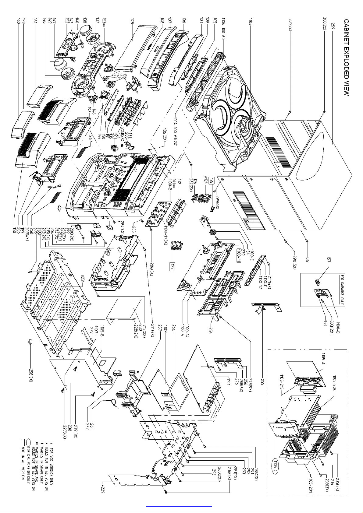
MAIN CABINET EXPLODED VIEW Page: 1 of 7
PDF created with pdfFactory trial version www.pdffactory.com
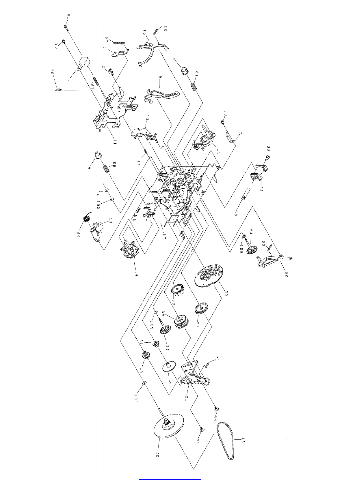
TAPE MECHANISM A EXPLODED VIEW Page: 2 of 7
PDF created with pdfFactory trial version www.pdffactory.com

TAPE MECHANISM B EXPLODED VIEW 1 Page: 3 of 7
PDF created with pdfFactory trial version www.pdffactory.com
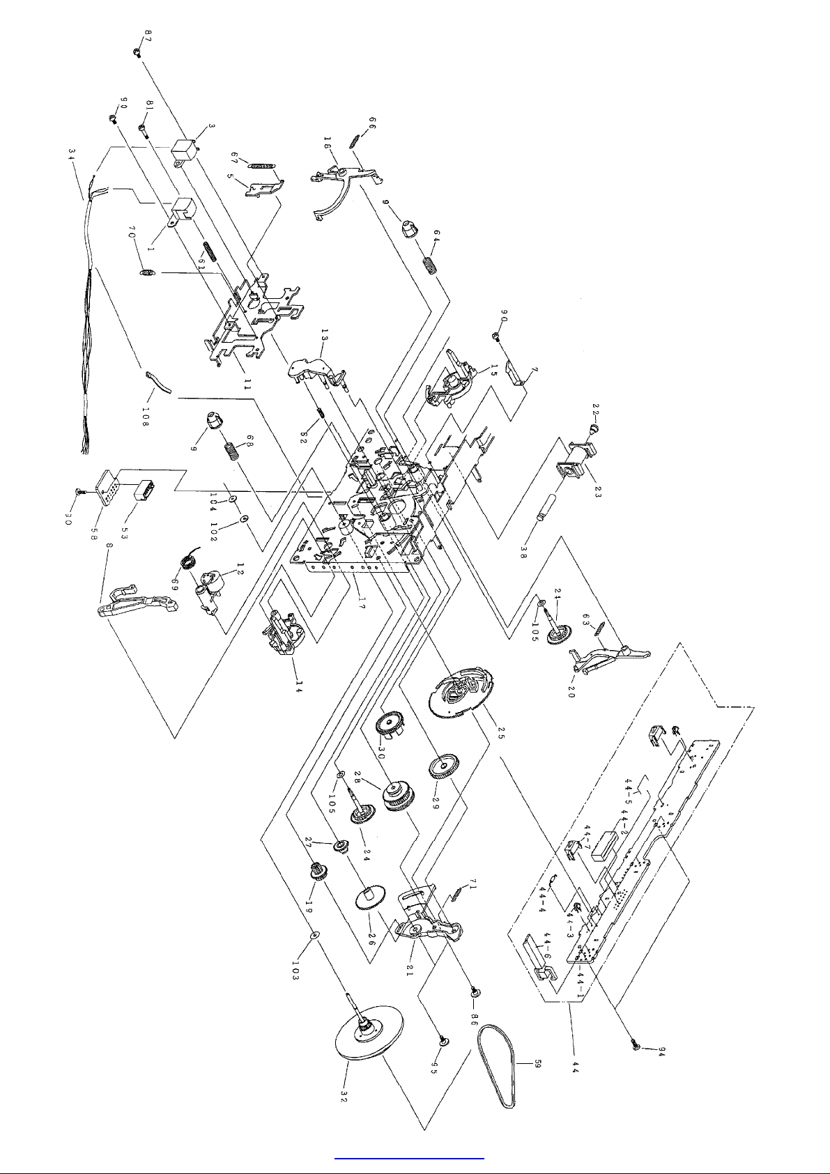
TAPE MECHANISM B EXPLODED VIEW 2 Page: 4 of 7
PDF created with pdfFactory trial version www.pdffactory.com

TAPE MECHANISM MOTOR EXPLODED VIEW Page: 5 of 7
PDF created with pdfFactory trial version www.pdffactory.com
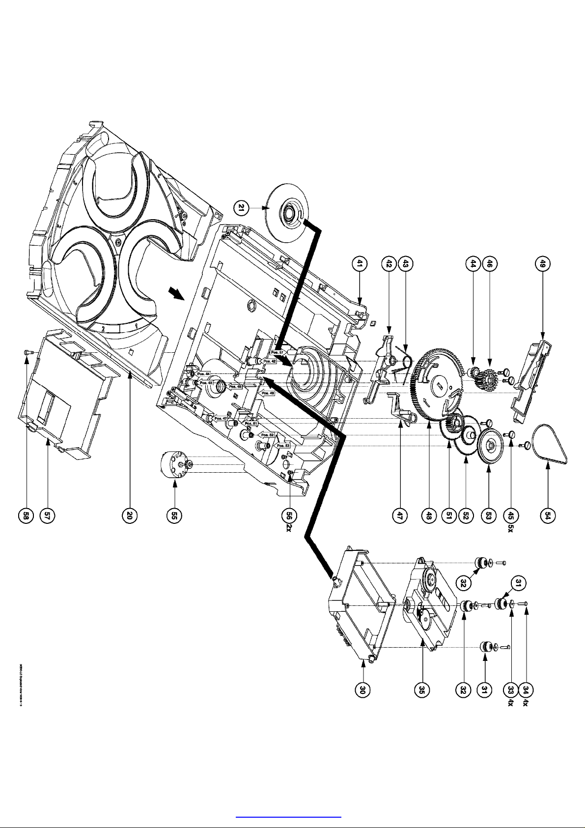
CD MECHANISM EXPLODED VIEW 1 Page: 6 of 7
PDF created with pdfFactory trial version www.pdffactory.com
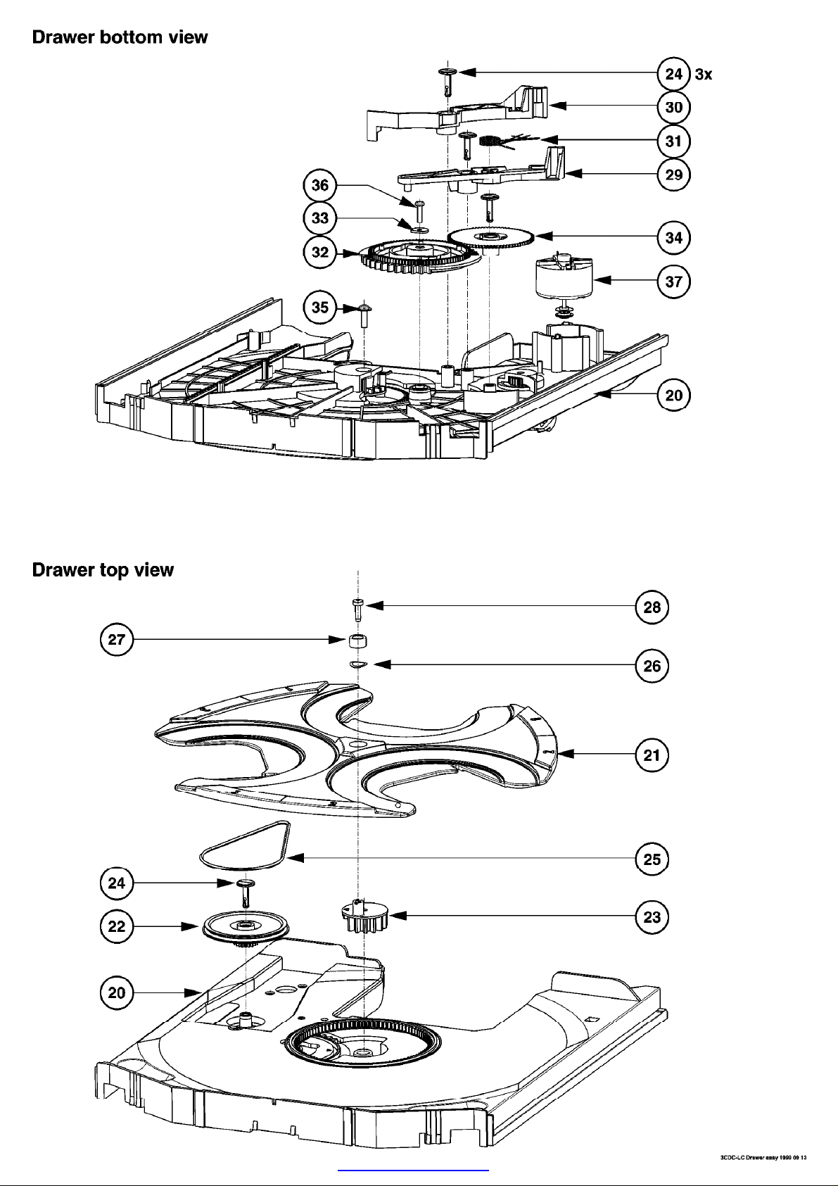
CD DRAWER MECHANISM TOP AND BOTTOM EXPLODED VIEW Page: 7 of 7
PDF created with pdfFactory trial version www.pdffactory.com

Philips Consumer Electronics
Technical Service Data
Service and Quality
Service Publications Dept.
One Philips Drive
P.O. Box 14810
Knoxville, TN 37914
Manual 1970
Model no.: FWC80C37
First Publish: 08-02-00
Rev. Date: 04-05-2005
Print Date: 05.04.2005
General Information
REFER TO SAFETY GUIDELINES
SAFETY NOTICE: ANY PERSON ATTEMPTING TO SERVICE THIS CHASSIS MUST FAMILIARIZE
HIMSELF WITH THE CHASSIS AND BE AWARE OF THE NECESSARY SAFETY PRECAUTIONS
TO BE USED WHEN SERVICING ELECTRONIC EQUIPMENT CONTAINING HIGH VOLTAGES.
CAUTION: USE A SEPARATE ISOLATION TRANSFORMER FOR THIS UNIT WHEN SERVICING
© Philips Electronics North America Corporation Visit our World Wide Web Site at http://www.forceonline.com
PDF created with pdfFactory trial version www.pdffactory.com

GENERAL INFORMATION
FWC80C37 Photograph
VERSION VARIATIONS
Type /Versions: FWC80
Features and
Board used:
/22 /34 /37
Aux. Input x x x
Line Out x x x
Surround Out
Subwoofer Out x x x
Digital Out x x x
Matrix Surround
CD Text
Dolby B x
RDS x x
News x x
Dolby Prologic (DPL)
Incredible Surround
Karaoke Features
Voltage Selector
Lower Power Standby (Clock Display Off) x x
Tuner Board - EC05 System x x
Tuner Board - Tuner 95 x
ETF7 ND/DD/FR - Chapter 9 x x
ETF7 DB/DD/FR - Chapter 9A x
SPECIFICATIONS
PDF created with pdfFactory trial version www.pdffactory.com

GENERAL:
Mains voltage : 110-127V/220-240V Switchable for /21/21M
120V for /37
220V for /33
220-230V for /22/34
230-240V for /30
Mains frequency : 50/60Hz
Power consumption
Low power standby : < 2W
Standby : < 15W
At 1/8 rated power out : 85W
Power consumption (/37)
Standby : < 15W
At 1/8 rated power out : 75W
Clock accuracy : < 4 seconds per day
Dimensions of center unit : 265 x 310 x 390mm
TUNER:
FM
Tuning range : 87.5-108MHz
65.81-74MHz for /34
Grid : 50kHz (and 30kHz for /34)
100kHz for /37
IF frequency : 10.7MHz ± 25kHz
Aerial input : 75 ohm coaxial
300ohm click fit for /37
Sensitivity at 26dB S/N : < 7µV
Selectivity at 600kHz bandwidth : > 25dB
Image rejection : > 25dB [> 75dB]
Distortion at RF=1mV, dev. 75kHz : < 3%
-3dB Limiting point : < 8uV
Crosstalk at RF=1mV, dev. 40kHz : > 18dB
MW (AM)
Tuning range : 531-1602kHz
530-1700kHz for /21/21M/37
Grid : 9kHz
10kHz for /21/21M/37
IF frequency : 450kHz ± 1kHz
Aerial input : Frame aerial
Sensitivity at 26dB S/N : < 4.0mV/M
Selectivity at 18kHz bandwidth : > 18dB
IF rejection : > 45dB
PDF created with pdfFactory trial version www.pdffactory.com

Image rejection : > 28dB
Distortion at RF=50mV, m=80% : < 5%
LW
Tuning range : 153-279kHz
Grid : 3kHz
IF frequency : 450kHz ± 1kHz
Aerial input : Frame aerial
Sensitivity at 26dB S/N : [< 7.0mV/M]
Selectivity at 18kHz bandwidth : [> 24dB]
IF rejection : [> 26dB]
Image rejection : [> 35dB]
Distortion at RF=50mV, m=80% : [< 5%]
AMPLIFIER:
Output power (6 ohms, 1kHz, 10% THD)
Left/Right : 2 x 60W
Output power (6 ohms, 60Hz-12.5kHz, 10% THD) /37
Left/Right : 2 x 50W
Frequency response within ±3dB : 60Hz-16kHz
Digital Sound Control (DSC) : Optimal, Classic, Techno, Jazz, Rock, Vocal
Virtual Environment Control (VEC) : Hall, Disco, Concert, Club, Cinema, Arcade
WOOX : 1, 2, 3
Headphone output at 32 ohms : 18mW ± 1dB
Input sensitivity
Aux. in : 500mV ± 2dB, 1kHz
Microphone : 4mV ± 2dB
Output sensitivity
Line out (Left/Right) : 500mV ± 2dB at 22 kohm
Subwoofer out at max. vol. (100Hz) : 1.3V ± 2dB at 22 kohm
CASSETTE RECORDER:
Number of tracks : 2 x 2 stereo
Tape speed : 4.76 cm/sec ± 2%
Wow and flutter : < 0.4% (DIN)
Fast-wind/Rewind time C60 : 130 sec.
Bias system : 75kHz ± 10kHz
Rec./PB freq. response within 8dB : 80Hz - 12.5kHz
Signal to noise ratio (unweighted) : > 44dB
1
PDF created with pdfFactory trial version www.pdffactory.com

COMPACT DISC:
Measurement done at output conn. of the CDC module.
Set level at 6 ohms speaker loads.
Frequency response : < ± 3dB for 63Hz - 14kHz
Signal/Noise ration (unweighted) : 60dBA
Signal/Noise ratio (A-weighted) : 67dBA
THD (30Hz-16kHz) : 1.5%
Channel difference (250Hz-10kHz) : < ± 2dB
Channel separation (20Hz-20kHz) : 30dB
Channel separation (1kHz) : 40dB
[....] Values indicated are for "Tuner 95 Board" only
1)
Default setting is OFF.
SERVICE AIDS:
Service Tools:
Universal Torx driver holder 4822 395 91019
Torx bit T10 150mm 4822 395 50456
Torx driver set T6 - T20 4822 395 50145
Torx driver T10 extended 4822 395 50423
Cassette:
SBC419 Test cassette CrO2 4822 397 30069
SBC420 Test cassette Fe 4822 397 30071
MTT150 Dolby level 200nWb/M 4822 397 30271
Compact Disc:
SBC426/426A Test disc 5 + 5A 4822 397 30096
SBC442 Audio Burn-in Test disc 1kHz 4822 397 30155
SBC429 Audio Signals disc 4822 397 30184
Dolby Pro-logic Test Disc 4822 395 10216
ESD Equipment:
Anti-static table mat - large 1200x650x1.25mm 4822 466 10953
Anti-static table mat - small 600x650x1.25mm 4822 466 10958
Anti-static wristband 4822 395 10223
Connector box (1Mý) 4822 320 11307
Extension cable
(to connect wristband to conn. box) 4822 320 11305
Connecting cable
(to connect table mat to conn. box) 4822 320 11306
Earth cable (to connect product to mat or box) 4822 320 11308
Complete kit ESD3
(combining all above products) 4822 320 10671
Wristband tester 4822 344 13999
PDF created with pdfFactory trial version www.pdffactory.com

WARNING
with the same potential as the mass of the set via a wrist wrap with resistance. Keep components and
All ICs and many other semiconductors are susceptible to electrostatic discharges (ESD). Careless
handling during repair can reduce life drastically. When repairing, make sure that you are connected
tools also at this potential.
Safety regulations require that the set be restored to its original condition and that parts which are
identical with those specified be used.
Warning !
Invisible laser radiation when open. Avoid direct exposure to beam.
"After servicing and before returning set to customer perform a leakage current measurement test
from all exposed metal parts to earth ground to assure no shock hazard exist. The leakage current
must not exceed 0.5mA."
Handling Chip Components
PDF created with pdfFactory trial version www.pdffactory.com
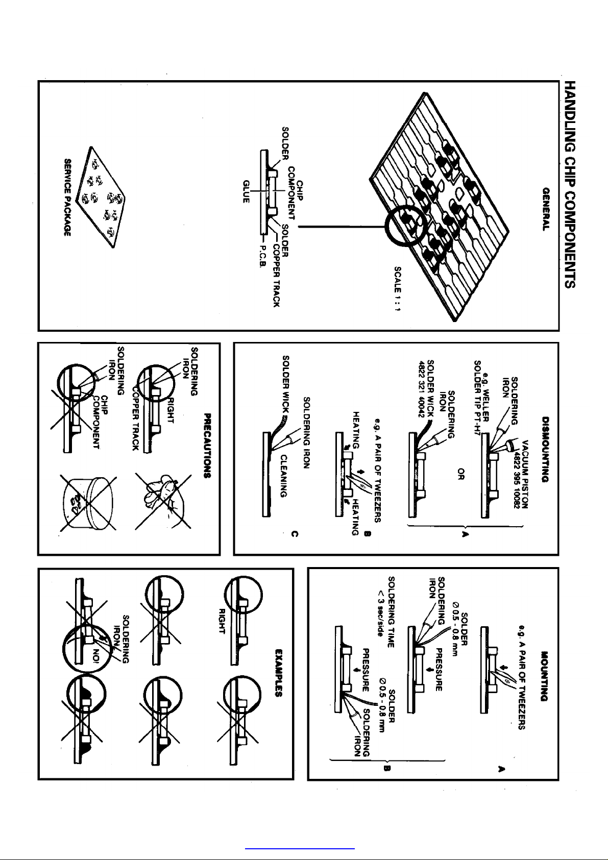
Handling Chip Components
PDF created with pdfFactory trial version www.pdffactory.com

Philips Consumer Electronics
Technical Service Data
Service and Quality
Service Publications Dept.
One Philips Drive
P.O. Box 14810
Knoxville, TN 37914
Manual 1970
Model no.: FWC80C37
First Publish: 08-02-00
Rev. Date: 04-05-2005
Print Date: 05.04.2005
Electrical Adjustments
REFER TO SAFETY GUIDELINES
SAFETY NOTICE: ANY PERSON ATTEMPTING TO SERVICE THIS CHASSIS MUST FAMILIARIZE
HIMSELF WITH THE CHASSIS AND BE AWARE OF THE NECESSARY SAFETY PRECAUTIONS
TO BE USED WHEN SERVICING ELECTRONIC EQUIPMENT CONTAINING HIGH VOLTAGES.
CAUTION: USE A SEPARATE ISOLATION TRANSFORMER FOR THIS UNIT WHEN SERVICING
© Philips Electronics North America Corporation Visit our World Wide Web Site at http://www.forceonline.com
PDF created with pdfFactory trial version www.pdffactory.com

Adjustments
Safety Instructions:
WARNING
All ICs and many other semiconductors are susceptible to electrostatic discharges
(ESD). Careless handling during repair can reduce life drastically. When repairing,
make sure that you are connected with the same potential as the mass of the set via
a wrist wrap with resistance. Keep components and tools also at this potential.
Safety regulations require that the set be restored to its original condition and that
parts which are identical with those specified be used.
Invisible laser radiation when open. Avoid direct exposure to beam.
After servicing and before returning the unit to the customer, perform a leakage
current measurement test from all exposed metal parts to earth ground to assure no
shock hazards exist. The leakage current must not exceed 0.5mA.
Schematic Notes:
1. All resistor values are in ohms, and the value multiplier is often
used to indicate decimal point location (e.g., 2K2 indicates 2.2K).
2. Resistor values with no multiplier may be indicated with either an
“E“ or ”R“ (e.g., 220E or 220R indicates 220 ohms).
3. All capacitor values are expressed in Microfarads (e.g., u = x10-6),
nanofarads (e.g., n = x10-9), or picofarads (e.g., x10
-12
).
4. Capacitor values may also use the value multiplier as the decimal
point indication (e.g., 2p2 indicates 2.2pF.).
5. Voltages listed on schematics often use a comma to indicate the
decimal point location as it is perceived as being ”more visible.“
Refer to individual schematic diagrams for all other component indications.
PDF created with pdfFactory trial version www.pdffactory.com

SERVICE AIDS:
Service Tools:
Universal Torx driver holder 4822 395 91019
Torx bit T10 150mm 4822 395 50456
Torx driver set T6 - T20 4822 395 50145
Torx driver T10 extended 4822 395 50423
Cassette:
SBC419 Test cassette CrO2 4822 397 30069
SBC420 Test cassette Fe 4822 397 30071
MTT150 Dolby level 200nWb/M 4822 397 30271
Compact Disc:
SBC426/426A Test disc 5 + 5A 4822 397 30096
SBC442 Audio Burn-in Test disc 1kHz 4822 397 30155
SBC429 Audio Signals disc 4822 397 30184
Dolby Pro-logic Test Disc 4822 395 10216
ESD Equipment:
Anti-static table mat - large 1200x650x1.25mm 4822 466 10953
Anti-static table mat - small 600x650x1.25mm 4822 466 10958
Anti-static wristband 4822 395 10223
Connector box (1Mohm) 4822 320 11307
Extension cable
(to connect wristband to conn. box) 4822 320 11305
Connecting cable
(to connect table mat to conn. box) 4822 320 11306
Earth cable (to connect product to mat or box) 4822 320 11308
Complete kit ESD3
(combining all above products) 4822 320 10671
Wristband tester 4822 344 13999
PC Board Location
Display Location of PC Boards
MEASUREMENT SETUPS
Display FM Tuner Measurement Setup
Display AM Tuner Measurement Setup
Display CD Measurement Setup
Display Tape Deck Recorder Measurement Setup
PDF created with pdfFactory trial version www.pdffactory.com

Service Test Program
Display Service Test Program
ADJUSTMENT TABLES
Display Tuner Adjustments - ECO5
Display Tuner CBA Top View
Display Tuner CBA Bottom View
Display Tape Mechanism Adjustment Table
Display Tape CBA Top View
Display Tape CBA Bottom View
PDF created with pdfFactory trial version www.pdffactory.com

Display Location of PC Boards
PDF created with pdfFactory trial version www.pdffactory.com

Display FM Tuner Measurement Setup
PDF created with pdfFactory trial version www.pdffactory.com
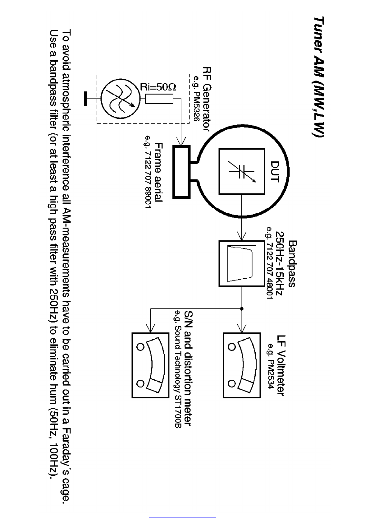
Display AM Tuner Measurement Setup
PDF created with pdfFactory trial version www.pdffactory.com
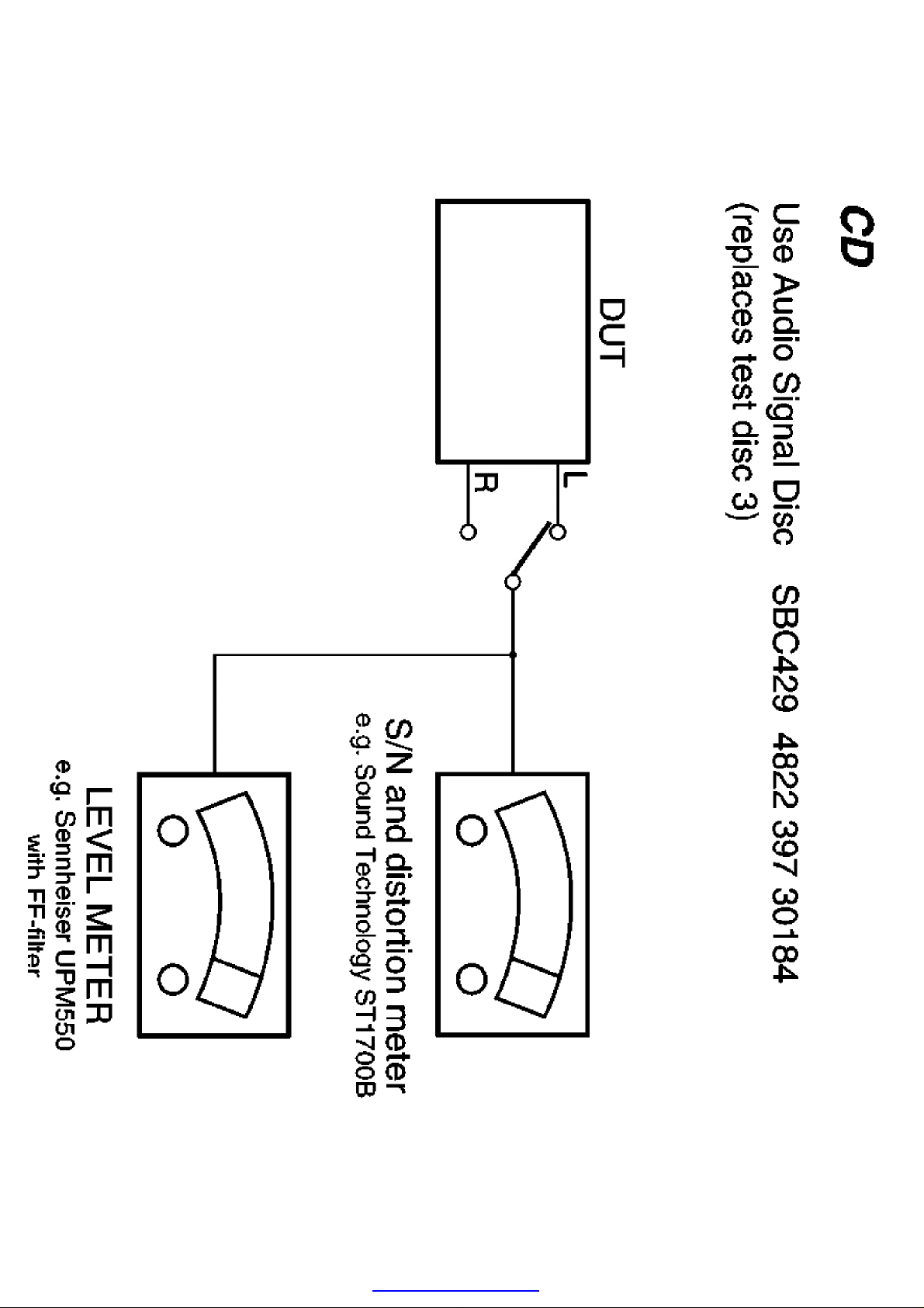
Display CD Measurement Setup
PDF created with pdfFactory trial version www.pdffactory.com
 Loading...