

Page 1
This symbol informs that there are contents that demand caution (including warnings).
This symbol indicates a prohibited matter.
This symbol indicates something that must be done.
WARNING
When installing the plasma display or making angle adjustments, be sure to make a request for service with the dealer
and ensure the work is performed according to this manual. Incorrect installation and angle adjustments may result in
the plasma display falling and causing injury.
To prevent the plasma display from falling, the strength of the installation place and the method of fastening must
support the combined weight of the plasma display and the mounting unit for an extended period of time as well as
withstand earthquakes. Improper installation may result in the plasma display falling and causing injury. Be sure to
observe the following matters.
- An electrical outlet should be used for the power supply of the plasma display. Direct connection to a power cable is
dangerous and should not be used. Please use a power outlet that can be reached to
allow the insertion and withdrawal of the power plug.
- Installation for Wooden Walls
The load should by all means be carried by beams, and when the strength of the beams is insufficient,
they should be strengthened.The installation should not be made to skirting or supporting members.
The load should also be carried by beams when there is a steel beam suspended ceiling; installation should not be
made to the ceiling suspension fittings.
- Installation for Concrete Walls
Commercial anchors that are strong enough to easily support the load of the plasma display should be used.
To ensure safety, bolts and screws must be tightened securely. Be sure to use the supplied parts for the brackets and
the other fittings. Failure to do so may result in the plasma display falling and causing injury.
When aligning the grooves of the display fittings to the fixed unit, check to make sure that they are securely engaged.
Failure to do so may result in the plasma display falling and causing injury.
Ignoring this indication and improper handling could be the
cause of personal injury such as a serious injury or death.
English
Do not modify any parts. Failure to do so may result in the plasma display falling and causing injury.
Do not use any damaged parts. Failure to do so may result in the plasma display falling and causing injury. In the event
that any parts are damaged, please contact the dealer.
This plasma display mounting unit is for use only with PHILIPS 50 inch plasma displays. Do not use with any other
equipment since the equipment could fall and cause injury.
CAUTION
Do not obstruct the ventilation holes of the plasma display. Doing so will prevent the dissipation of heat and may result
a fire. Do not use the plasma display in the following ways:
Do not install the plasma display in a tight place where ventilation is poor, place a cover on it, etc.
Do not install the plasma display in front of the vents of an air conditioner or heater, or in a place where there is
strong vibration. Doing so may result in fire or electrical shock.
Do not install the plasma display in humid or dusty places, or where it will be exposed to greasy smoke or steam (such
as near cooking equipment or humidifiers). Doing so may result in a fire. Do not use the plasma display outdoors.
Doing so may result in a fire or electrical shock.
The plasma display shall not be exposed to dripping or splashing and no objects filled with liquids, such as vases, shall be
placed on it.
Leave sufficient space around the plasma display when installing it.
Failure to do so may load to head buildup within the display and could result in fire.
Hold the plasma display in place while attaching it to the unit. Failing to do so may lead to it falling and causing injury.
Ignoring this indication and improper handling could cause injury
to a person or damage to the surrounding household belongings.
Installation Location
Avoid rooms with a lot of dust, humidity, greasy smoke, or tobacco smoke.
Dirt will adhere to the surface of the display monitor screen and cause a deterioration in image quality.
Avoid places in which the screen is exposed to direct sunlight or illumination light.
When surrounding light hits the screen directly, the image appears washed out and is difficult to view.
Avoid places which reach high temperatures or low temperatures.
Such extreme temperatures will cause breakdown.
11
Page 2
Unpacking and wall mounting instructions
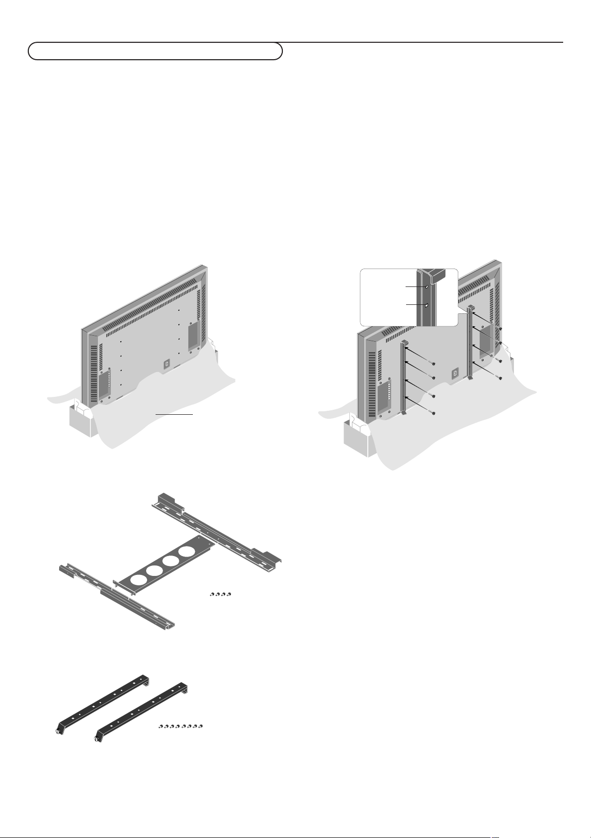
Protective sheet
round hole
square hole
Special technology is required in the mounting of the plasma display.
Such work should never be undertaken by the customer.
For the safety of the customer, we ask that the installation work be started after careful attention is paid to the strength of the
mounting location to be sure it will withstand the weight (about 46 kg) of the plasma display and mounting hardware.
Be sure that two or more persons engage in the installation work.
Be careful not to lose any of the removed screws or other parts.
Remove the packaging
&
Open the upper carton which packages the plasma display
and remove the styrofoam.
é Remove the upper carton and open the protective sheet.
Attach the display fittings
“
With the display standing in its packaging carton, align the
round holes of the display fittings with the screw holes of
the plasma display, then fasten the display fittings using the
supplied screws.
Package parts list
wall mount unit
display fittings
Installation of the display fittings can also be performed by
laying down the plasma display on a flat surface.
Remove the plasma display form the carton, place the
protective sheet that was used in the packaging on a flat
surface (which is larger than the display), then lay the
display down on top of this with the screen surface facing
downward.
M4 screws x 4
M4 screws x 8
Unpacking and wall mounting instructions
2
Page 3
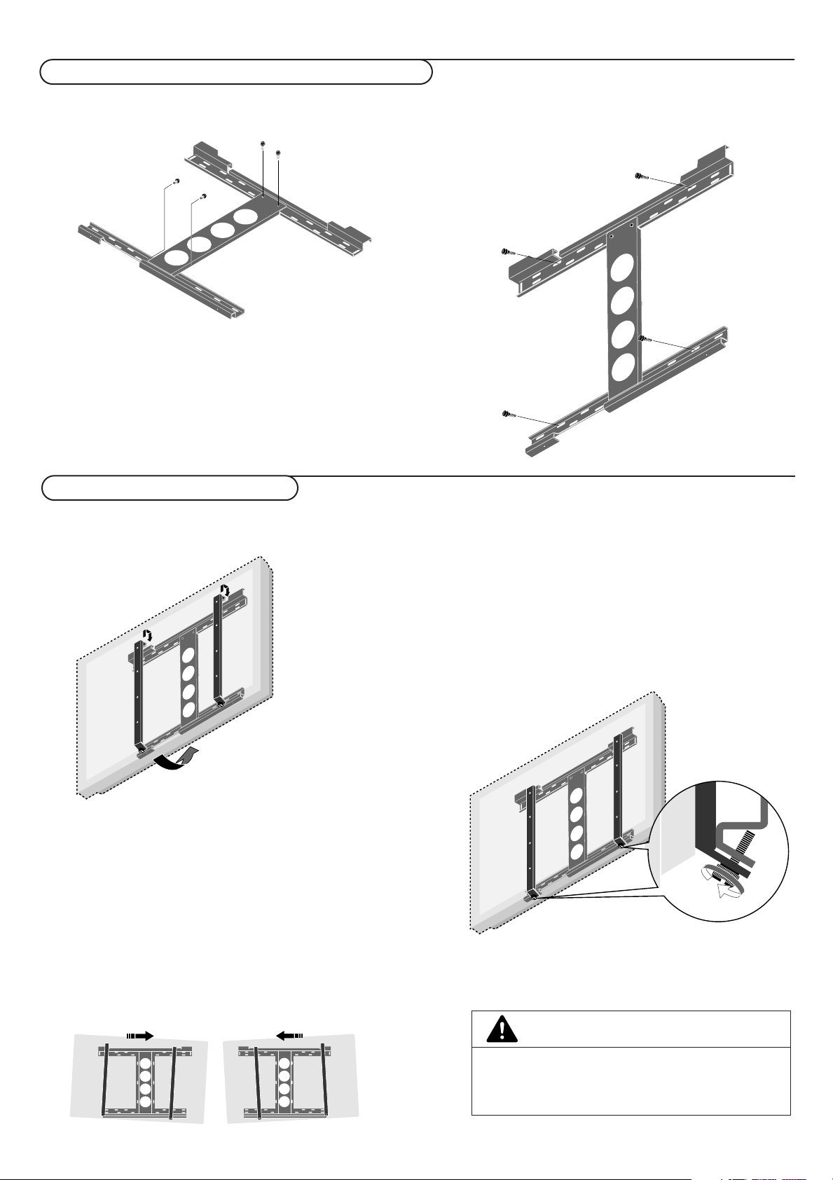
Assembling and mounting the wall mount unit
& Securely fasten the upper and lower wall-side fittings to the
middle wall-side fitting with the four supplied M4 screws.
é Fasten the unit with commercial anchors or the four screws.
Be sure that the anchors or screws are fastened at a position
where there is a post.
Note: Use anchors and screws to suit the various wall types.
The enclosed template can be used for general positioning only.
Mounting the plasma display
Make sure that the wall mount unit is being fixed securely
enough so that it meets safety standards.
& Mount the display (to which the display fittings have already
been attached) to the wall mounting unit.
é Fit the upper hooks of the display fittings into the grooves
of the (upper) wall fittings and adjust for level positioning.
Note: It is recommended that the power cable and various signal
cables be plugged into the display before mounting the display.
After mounting the display, plugging in the cables may be difficult.
If the display is tilted to the left or right, the display fitting is
not properly placed on the wall mounting unit. Slide in the
direction of the lower side and adjust for level positioning.
“ Anchor the plasma display.
Align the thumb screw, which is located at the bottom of
the display fitting, with the hole of the (lower) wall-side
fitting and tighten to anchor.
Fasten securely until the screw ceases to turn.
To remove the display, loosen the thumb screws until they
come out of the hole.
Pull the bottom portion of the display towards you and lift
upward to release the display.
CAUTION
Firmly support the display when mounting it.
Failure to do so may result in the plasma display falling
and causing injury.
3Unpacking and wall mounting instructions
Page 4
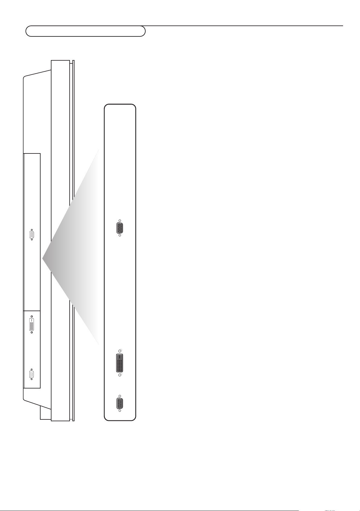
Connect Peripheral Equipment
You may connect 2 possible VGA sources (VGA or RGB Digital (DV I) to the left
side of the monitor.
VGA
DVI
EXTERNAL
CONTROL
VGA Input for analog RGB signal of PC, etc.
DVI Inputs a PC with a digital RGB signal.
RS 232c Serial I/O port
This connector allows you to control your monitor via external
equipment (e.g. PC) and a replacement of the remote control
4 Connect Peripheral Equipment
Page 5

R6 / AA
Connect your computer
Note: When you connect a computer to this monitor, attach the supplied ferrite
cores. If you do not do this, this monitor will not comply with the mandatory CE or CTick standards.
& Set the (large) ferrite core on one end of the power cable (supplied).
é In case of a computer with a digital RGB output set the (small) ferrite cores
on both ends of the DVI cable (not supplied).
“ Click the lids tightly until the clamps click.
‘ Use the bands to secure the ferrite cores.
Directly to the plasma display
& Connect one end of a VGA cable supplied to the video card of the computer
and the other end to the
with a digital
connectors firmly with the screws on the plug.
See Table of Signals Supported, p. 11.
RGB output) connector at the rear side of the monitor. Fix the
VGA (or to RGB Digital DVI in case of a computer
é In case of a Multimedia computer, connect the audio cable to the audio
outputs of your computer and to the audio inputs of an additional audio
receiver.
To an electronic receiver box
See the handbook of the receiver box.
& Connect one end of a VGA cable to the video card of the computer and the
other end to the
the connectors firmly with the screws on the plug.
VGA IN connector at the rear side of the receiver box. Fix
é In case of a Multimedia computer, connect the audio cable to the audio
outputs of your computer and to the
inputs of the receiver box.
AUDIO VGA IN R (right) and L (left)
Operation
Power On/Off
Mains inlet
& Insert the mains plug supplied into the mains inlet at the bottom of the
monitor and in the wall socket. For safety, please, only use the supplied rimearthed mains cord which has to be inserted in a grounded socket.
é Remote control: remove the cover of the battery compartment.
Insert the 2 batteries supplied (Type LR6/AA-1.5V).
The batteries supplied do not contain the heavy metals mercury and cadmium.
Nevertheless in many countries batteries may not be disposed of with your
household waste. Please check on how to dispose of batteries according to local
regulations.
“ Make sure that your receiver box and/or PC are switched on and that
your PC is in the correct display mode (see p. 11).
‘ Switch the plasma display on : Press the power button B at the
bottom side of the monitor.
A green indicator lights up and the screen comes on.
When the plasma display does not receive a supported vga signal or is not
connected to a receiver box, the screen switches to standby and the red
indicator lights up.
Warning:The
display completely from the mains.
POWER ON/OFF switch does not disconnect the plasma
5Connect your computer + Operation
Page 6

POWER
BRIGHTNESS
CONTRAST
ZOOM OUTZOOM INZOOM ON/OFF
VGA AV1 AV2 AV3
MUTE
AV MUTE
q
1
2
3
4
5
6
7
8
9
0
V
CH/PR
MENU
OK
¬
B
VGA
press repeatedly to select your computer
connected to the
VGA or to the DVI (digital
RGB) connector.
Use of the remote control
B to switch to standby or on again
(Does not operate when
STANDBY indicator of the plasma display
POWER/
is off).
BRIGHTNESS +/-
to adjust the brightness level of the picture
CONTRAST +/-
to adjust the contrast level of the picture
ZOOM ON/OFF
to activate/de-activate the zoom function.
ZOOM IN/OUT
to adjust the zoom factor and to change
the magnification of the picture when
zoom is activated.
MENU to switch the menu on/off
cursor keys to select your choice and to
alter a selected adjustment.
OK to activate your choice
V No function
¬ Mute key No function
CH/PR Programme selection
To browse through the sources selected.
AV MUTE to mute the picture or
restore it if the plasma display is used in
VGA mode.
the
When activated a green indicator starts
blinking in front of the plasma display.
q Picture format
Press the q key to switch between the
different picture formats.
Picture format
Press the q key to switch between the different picture formats.
Note: When the setting of
TRUE in place of NORMAL.
VGA-mode
4:3 signals Wide signals
Normal/True True
Full Full
Use of the remote control
6
PICTURE SIZE in the OPTIONS 2 menu, p. 10, is off, the picture format of RGB-input pictures will be
Page 7

Use of the menus and the menu system
& Press the MENU key on the remote control to display/cancel the MAIN MENU.
é Use the cursor key in the up/down directions to select the menus.
MAIN MENU
PICTURE
SCREEN
OPTIONS1
OPTIONS2
SET-UP
FREQUENCY
J
SELECT
M
SELECT MENU OFF
“ Press the cursor right to access the menu.
‘ Use the cursor key in the up/down directions to select the menu items.
( In case of a slider, move the cursor left/right to adjust.
§ Press the MENU key repeatedly to return or to switch the menu off.
Note: Only when in the US English language has been selected (see
LANGUAGE
Picture menu
Note:
If the message “
be sure the Picture mode is set to
Contrast
This control allows you to adjust the contrast level of the picture.
PICTURE
CONTRAST
BRIGHTNESS
SHARPNESS
(COLOUR)
(TINT)
PICTURE MODE
COLOUR TEMP.
(NOISE RED.)
J
SELECT
L M
L M
ADJUST MENU RETURN
Brightness
This control allows you to adjust the brightness level of the picture.
Sharpness
This control allows you to adjust the edge definition of a picture.
(Colour)
This control allows you to adjust the saturation level of the colours to suit your
personal preference.
(Tint)
This control allows you to compensate for the Colour variations in NTSC
encoded transmissions.
SET-UP menu,
, p. 10), the menu items will be displayed with additional icons.
CAN NOT ADJUST” appears when trying to adjust the picture settings,
MEMORY.
WHITE BALANCE
GAIN
RED
GREEN
BLUE
BIAS
RED
GREEN
BLUE
J
SELECT
L M
ADJUST MENU RETURN
L M
Picture mode
This control allows you to select a picture mode according to the brightness of
the environment in which you are viewing the pictures on the monitor display.
Press the cursor left/right to select
bright room,
RESET to reset the picture to the settings predefined in the factory.
MEMORY to keep the picture adjustments you adjusted yourself,
THEATRE in a dark room, NORMAL in a
Colour temperature
This control allows you to select the Colour temperature and the white balance
of the picture.
& Press the cursor left/right to select 1 (bluer), 2 (standard), 3 (redder) or
PRO (white balance).
é Select PRO to adjust the white balance for bright and dark pictures.
“ Press the OK key to display the WHITE BALANCE menu.
‘ Select and adjust Red-Green-Blue GAIN to adjust the white balance for signal
level.
Select and adjust Red-Green-Blue
level.
(Noise reduction)
This control allows you to reduce the noise in the picture due to poor reception
or poor picture quality.
OFF, NR-1, NR-2 or NR-3 according to the level of noise present.
Select
Note: Select
RESET in the OPTION 1 menu, p. 8, to restore the predefined factory PICTURE
settings.
BIAS to adjust the white balance for black
7Use of the menus and the menu system
Page 8

SCREEN
MODE NORMAL
V-POSITION
H-POSITION
AUTO PICTURE
FINE PICTURE
PICTURE ADJ.
J
SELECT
L M
ADJUST MENU RETURN
Screen settings menu
In this menu you are allowed to adjust the position of the picture and to
correct the flickering of the picture menu items.
Note:
AUTO PICTURE, FINE PICTURE and PICTURE ADJ. menu items are not available with
- The
signals from a Video source.
- The menu items
AUTO PICTURE OFF
RESET in the OPTIONS1
- Select
FINE PICTURE and PICTURE ADJ. are available only when you select
.
menu to restore the predefined factory PICTURE
settings.
& Select MODE and press the cursor left/right to select a picture format
NORMAL or FULL in VGA-mode).
(
é Select AUTO PICTURE ON or OFF. When having selected ON,
the PICTURE ADJ. and FINE PICTURE adjustments are made automatically.
When having selected
OFF, the PICTURE ADJ. and FINE PICTURE
adjustments can be made manually.
FINE PICTURE adjusts for flickering; PICTURE ADJ. adjusts for striped
patterns on the picture.
“ Select V-POSITION, H-POSITION to adjust the position of the picture.
V-POSITION adjusts the vertical position,
H-POSITION adjusts the horizontal position,
OPTIONS1
OSD ON
OSD ADJ.
POWER MGT.
GRAY LEVEL
CINEMA MODE
DVI ADJ.
LONG LIFE
RESET
J
SELECT
OSD ADJ.
123
456
789
L M
ADJUST MENU RETURN
Options 1 menu
OSD
Select
OFF if you do not want On screen information like input source, screen
mode, etc. to appear on screen during presentation, etc.
OSD ADJ.
OSD ADJ. 1-9 to position the menus that appear on screen. The
Select
position can be set between 1 and 9.
POWER MGT. (only in VGA mode)
POWER MGT. ON to turn the power management function on.
Select
The power management function is an energy-saving function and
automatically reduces the monitor’s power consumption if the computer’s
keyboard or mouse in not operated for a certain time. (See also the
computer’s operating instructions).
Note: if the computer’s power is not turned on, the power management function is set
OFF.
to
GRAY LEVEL
This control allows you to set the gray level for the sides of the screen when
a normal 4:3 picture mode is displayed. It adjusts the brightness of the black
for the sides of the screen.The standard is 0 (black) and the level can be
adjusted from 0 to 15.The predefined factory setting is 3 (dark gray).
CINEMA MODE
CINEMA MODE ON to automatically discriminate and project the film
Select
image in a cinema mode suited to the picture (NTSC, PAL60, 480I, (60Hz)
only).
8 Use of the menus and the menu system
Page 9

LONG LIFE
(PLE AUTO)
INVERSE
SCREEN WIPER
DVI ADJ
This control allows you to select the most appropriate setting when the
picture input from the DVI input extension is distorted. Select 1, 2 or 3.
Note: When you adjust the
DVI ADJ., the position of the menu display will change. In
such a case, be sure to adjust the position.
PRESS OK TO SET TIMER FUNCTIONS
J
SELECT
INVERSE/WT
WORKING TIME • 1h
WAITING TIME • h
J
SELECT
SCREEN WIPER
WORKING TIME • 1h
WAITING TIME • h
J
SELECT
L M
ADJUST MENU RETURN
• 30m
m
L M
ADJUST MENU RETURN
• 30m
• m
SPEED •
L M
ADJUST MENU RETURN
LONG LIFE
This control allows you to select a setting to prevent or to reduce burn-in of
the screen.
& Select LONG LIFE.
é Press the cursor right to enter the menu.
“ Select PLE AUTO or LOCK (only with VGA and DVI inputs).
AUTO automatically adjusts the brightness of the screen to suit the picture
quality.
LOCK sets the brightness level to minimum.
‘ Select INVERSE ON, OFF or WT.
ON : the picture is displayed alternately between positive and negative image.
WT : the entire screen turns white.
OFF : the inverse mode does not function.
When having selected on, press the
OK key to enter the INVERSE/WT menu
and to set the timer functions.
WORKING TIME and enter the hours (h) and minutes (m) with the
Select
cursor keys to select the time the inverse mode has to be active.
WAITING TIME and enter the hours (h) and minutes (m) with the
Select
cursor keys to select the time after which the inverse mode should become
active.
( Select SCREEN WIPER ON or OFF.
ON and press the OK key: a white vertical bar is moving from left to
Select
right over the screen to prevent burn-in.
Set the timer functions (see the inverse mode) and the speed (from 1, fast, to
5, slow) with the cursor keys in the
SCREEN WIPER menu.
RESET
This control allows you to reset all the
predefined factory values and settings.
& Select RESET.
é Press the OK key.
“ Select RESET.
When the message
to the predefined factory values.
SETTING NOW disappears, all the settings are restored
OPTIONS 1 and 2 settings to the
9Use of the menus and the menu system
Page 10

OPTIONS2
RGB SELECT
HD SELECT
PICTURE SIZE
J
SELECT
M
SELECT MENU RETURN
Options 2 menu
Setting a computer image to the correct RGB select screen
This control allows you to select the most appropriate RGB Select mode for
a moving image, such as video mode, wide mode or a digital broadcast.
& Select RGB SELECT with the cursor up/down.
é Press the cursor left/right to select one of the modes in order to display
the following signals correctly:
AUTO: automatically selects the suitable mode for the specifications of input
signals as listed in the table "Computer input signals supported by this
system", see p. 11.
STILL: to display VESA standard signals. Use this mode for a still image from a
computer.
MOTION: the video signal will be converted to RGB signals to make the
picture more easily viewable. Use this mode for a motion image from a
computer.
WIDE 1: when a 852 dot x 480 line signal with a horizontal frequency of
31.7 kHz is input, the image may be compressed horizontally. To prevent this,
WIDE 1.
select
WIDE 2: when a 848 dot x 480 line signal with a horizontal frequency of
31.0 kHz is input, the image may be compressed horizontally.
To prevent this, select
DTV: select this mode when watching digital broadcasting (480p).
WIDE 2.
Setting high definition images to the suitable screen size
This control allows you to set whether the number of vertical lines of the
input high definition image is 1035 or 1080.
& Select HD SELECT.
é Press the cursor left/right to select the correct HD mode:
- 1080A for special digital broadcasts (e.g. DTC 100)
- 1080B for standard digital broadcasts
- 1035I for Japanese "High Vision" signal format.
SET-UP
LANGUAGE • ENGLISH •
PRESS OK TO CONFIRM
FREQUENCY
H. FREQUENCY • 43.3 KHZ
V. FREQUENCY • 85.0 KHZ
H. POLARITY • NEGATIVE
V. POLARITY • NEGATIVE
MODE • 9
RESOLUTION • 640 X 480
J
SELECT
M
SELECT MENU RETURN
Setting the picture size for RGB input signals
This control allows you to select the picture size mode for RGB input signals
ON or OFF.
ON: NORMAL and FULL can be selected for widescreen switching
OFF: TRUE and FULL can be selected for widescreen switching.
Note: Select
RESET in the OPTIONS 1 menu to reset all the OPTIONS 1 and 2 settings
to the predefined factory values and settings.
Set-up menu
Setting the menu language
& Use the cursor down to select LANGUAGE.
é Use the cursor left/right to select one of the languages which will be used
to display the menus.
“ Press the OK key to confirm.
Frequency menu
This control allows you to check the frequencies the polarities and the
resolution of the signals currently being input from a computer.
The menu items cannot be selected nor controlled and are displayed in
English only.
10
Use of the menus and the menu system
Page 11

Table of Signals Supported
Supported resolution
• When the screen mode is
• When the screen mode is
• When the screen mode is
Computer input signals supported by this system
NORMAL, each signal is converted to a 1024 dots x 768 lines signal (except for *2,3,4).
TRUE, the picture is displayed in the original resolution.
FULL, each signal is converted to a 1364 dots x 768 lines signal (except for *3).
Model
Signal Type
*IBM PC/AT
compatible
computers
Work Station
(EWS4800)
Work Station
Dots x lines
640 x 400
640 x 480
848 x 480
852 x 480
800 x 600
1024 x 768
1152 x 864
1280 x 768
1360 x 765
1376 x 768
1280 x 1024
1600 x 1200
1280 x 1024
1280 x 1024
*1
Vertical
frequency
(Hz)
70.1
59.9
72.8
75.0
85.0
100.4
120.4
60.0
60.0
56.3
60.3
72.2
75.0
85.1
99.8
120.0
60.0
70.1
75.0
85.0
100.6
75.0
56.2
60.0
59.9
60.0
75.0
85.0
60.0
65.0
70.0
75.0
60.0
71.2
72.0
Horizontal
frequency
(kHz)
31.5
31.5
37.9
37.5
43.3
51.1
61.3
31.0
31.7
35.2
37.9
48.1
46.9
53.7
63.0
75.7
48.4
56.5
60.0
68.7
80.5
67.5
45.1
47.7
48.3
64.0
80.0
91.1
75.0
81.3
87.5
93.8
64.6
75.1
78.1
Horizontal
NEG
NEG
NEG
NEG
NEG
NEG
NEG
POS
NEG
POS
POS
POS
POS
POS
POS
POS
NEG
NEG
POS
POS
NEG
POS
POS
POS
NEG
POS
POS
POS
POS
POS
POS
POS
NEG
NEG
--
(HP)
Work Station
(SUN)
Work Station
(SGI)
1152 x 900
1280 x 1024
1024 x 768
1280 x 1024
66.0
76.0
76.1
60.0
60.0
61.8
71.7
81.1
49.7
63.9
C Sync
C Sync
C Sync
--
--
IDC-3000G
PAL625P
NTSC525P
768 x 576
640 x 480
50.0
59.9
31.4
31.5
NEG
NEG
*1 Only when a graphic accelator board that is capable of displaying 852 x
480.
*2 This signal is converted to a 1228 dots x 768 lines signal.
*3 The picture is displayed in the original resolution.
*4 The aspect ratio is 5:4. This signal is converted to a 960 dot x 768 line
signal.
*5 Normally the RGB select mode suite for the input signals is set
automatically. If the picture is not displayed properly, set the RGB mode
prepared for the input signals listed in the table above.
*6 Other screen modes (ZOOM and STADIUM) are available as well.
Sync Polarity
Vertical
NEG
NEG
NEG
NEG
NEG
NEG
NEG
POS
NEG
POS
POS
POS
POS
POS
POS
POS
NEG
NEG
POS
POS
NEG
POS
POS
POS
POS
POS
POS
POS
POS
POS
POS
POS
NEG
NEG
--
C Sync
C Sync
C Sync
--
--
NEG
NEG
Presence
Horizontal
YES
YES
YES
YES
YES
YES
YES
YES
YES
YES
YES
YES
YES
YES
YES
YES
YES
YES
YES
YES
YES
YES
YES
YES
YES
YES
YES
YES
YES
YES
YES
YES
YES
YES
--
--
--
--
--
--
--
YES
YES
Vertical
YES
YES
YES
YES
YES
YES
YES
YES
YES
YES
YES
YES
YES
YES
YES
YES
YES
YES
YES
YES
YES
YES
YES
YES
YES
YES
YES
YES
YES
YES
YES
YES
YES
YES
--
--
--
--
--
--
--
YES
YES
Screen mode
NORMAL
(4:3)
*2
YES
YES
YES
YES
YES
YES
YES
--
--
YES
YES
YES
YES
YES
YES
YES
*3
YES
*3
YES
*3
YES
*3
YES
*3
YES
YES
--
--
--
*4
YES
*4
YES
*4
YES
YES
YES
YES
YES
*4
YES
*4
YES
*4
YES
YES
YES
*4
YES
*3
YES
*4
YES
*6
YES
*6
YES
TRUE
YES
YES
YES
YES
YES
YES
YES
YES
YES
YES
YES
YES
YES
YES
YES
YES
--
--
--
--
--
--
--
--
--
--
--
--
--
--
--
--
--
--
--
--
--
--
--
--
--
--
FULL
(16:9)
YES
YES
YES
YES
YES
YES
YES
YES
YES
YES
YES
YES
YES
YES
YES
YES
YES
YES
YES
YES
YES
YES
YES
YES
YES
YES
YES
YES
YES
YES
YES
YES
YES
YES
YES
YES
YES
YES
YES
YES
YES
YES
*3
*6
*6
Note:
• While the input signals comply with the resolution listed in the table above, you may
have to adjust the position and size of the picture or the fine picture because of
errors in synchronisation of your computer.
• When a 1280 dot x 1024 line signal or 1600 dot x 1200 line signal is input to the
monitor, the picture will be compressed.
• This monitor has a resolution of 1365 dot x 768 line. It is recommended that the
input signal should be XGA, wide XGA, or equivalent.
• With digital input some signals are not accepted.
• The sync may be disturbed when a nonstandard signal other than the
aforementioned is input.
*”IBM PC/AT” and “VGA” are registered trademarks of IBM, Inc. of the United States
RGB
select
--
STILL
--
STILL
--
--
--
WIDE2
WIDE1
STILL
STILL
--
--
--
--
--
STILL
--
STILL
--
--
STILL
WIDE1
WIDE1
WIDE2
STILL
--
--
--
--
--
--
--
--
--
--
--
--
--
--
--
MOTION
*5
11Table of Signals Supported
Page 12

Before calling Service
Ambient temperature
Do not hang up the monitor above a
central heating or other heating sources.
If the power/standby indicator in front is
red and blinking, the temperature inside
the monitor has become too high and has
activated the protector. The monitor will
be turned off. Unplug the power cord and
wait for the monitor to cool down.
Care of the screen
Clean the anti-reflex coated flat glass
screen with a slightly damp soft cloth. Do
not use abrasives solvents as it can
damage the glass surface of the screen.
Plasma Display characteristics
Caution:A video source (such as a video
game, DVD, or video information channel)
which shows a constant non-moving
pattern on the monitor, can cause damage
to the screen.When your Flat-Monitor is
continuously used with such a source, the
pattern of the non-moving portion of the
game (DVD, etc.) could leave an image
permanently on the screen.When not in
use, turn the video source
To prevent or to reduce burn-in of the
screen, select a
OPTIONS1 menu. See p. 8.
Very incidentally and after a longer period
of unuse (approx. 1 year) the screen may
display some strange colour deficiencies.
This is quite normal for plasma displays
and these effects will disappear after the
set has been turned on for some time.
A plasma display consists of more than 1,2
Million colour pixels. It is within industry
standards that very few pixels (< 0.001%)
may be defective, even for a new set.
There is however no reason to doubt
about the quality of the set.
The plasma display technology operates
with rare gases which are being influenced
by air pressure. Up to an altitude of
2000m above sea-level (local air pressure
equal or above 800 hPa), the display is
functioning fine. Operating the set at a
higher altitude (lower air pressure), the
picture becomes unstable and the picture
performance is deteriorating.
LONG LIFE
OFF.
setting in the
The plasma display might then also
produce a humming sound.After bringing
the set below 2000 m (local air pressure
equal or above 800 hPa) it works fine
again.Transportation has no influence.
Control of peripheral equipment
The infrared radiation of the screen may
influence the reception sensitivity of other
peripherals. Solution: replace the batteries
of the remote control or change position
of other equipment. E.g. keep away a
wireless headphone from within a radius
of 1,5 m.
No stable or not synchronised VGA
picture
Check if you have selected the correct
display mode in your PC. See Table of
Signal Supported.
No picture
Are the supplied cables connected
properly? (The power cable to the display,
the VGA cables,...)
Is your PC switched on?
Do you see a black screen and the
indicator in front of the monitor lights up
green, this means that the display mode is
not supported.
Switch your VGA source to a correct
mode.
Remote control
If your monitor no longer responds to the
remote control, the batteries may be
exhausted.
If your problem is not solved:
Switch your monitor off and then on
again.
Never attempt to repair a defective
monitor yourself.
Check with your dealer or call a video
technician.
Transport
Keep the original packaging to transport the
monitor if needed.
End of life directives
Philips is paying a lot of attention to
produce environmentally-friendly in green
focal areas.Your new monitor contains
materials which can be recycled and
reused.
At the end of its life specialised companies
can dismantle the discarded monitor to
concentrate the reusable materials and to
minimise the amount of materials to be
disposed of.
Please ensure you dispose of your old
monitor according to local regulations.
How to dispose of batteries ?
The batteries supplied do not contain the
heavy metals mercury and cadmium.
Nevertheless in many countries batteries
may not be disposed of with your
household waste. Please ensure you dispose
of batteries according to local regulations.
Miscellaneous
. Ambient temperature: + 5~ + 40°C
. Maximum operating altitude:
2000 m/6526 ft
(min. air pressure 800hPa)
. Mains: AC 100-240V
. Standby consumption: 1 W
. Weight (excl. packaging)
Display: 46 kg
. Dimensions (wxhxd):
Display: 124,2 x 76,7 x 11 inch
. Wall mounting bracket included
Settings are out of adjustment
Select
RESET in the OPTIONS 1 menu, p. 8
to restore the predefined factory settings.
Before calling Service
12
 Loading...