

Philips Color TV User Manual

Directions for Use
Model No.:
Serial No.:
Color TV
Color TV
Need help?
Call us!
Philips representatives are ready to help you with any questions
about your new product. We can guide you through
Connections, First-time Setup, or any of the Features.
We want you to start enjoying your new product right away!
CALL US BEFORE YOU CONSIDER
RETURNING THE PRODUCT.
Visit us on the web at
www.philips.com
Important!
Return your
Warranty
Registration Card
within 10 days.
See why inside.
3141 055 22001Printed in China

2
Once your PHILIPS purchase is registered, you’re eligible to receive all
the privileges of owning a PHILIPS product. So complete and return the
Warranty Registration Card enclosed with your purchase at once. And
take advantage of these important benefits.
Return your Warranty Registration Card today to
ensure you receive all the benefits you’re entitled to.
Congratulations on your purchase, and welcome to the
“family!” To get the most from your PHILIPS product,
you must return your Warranty Registration Card within
10 days. So please mail it to us right now!
Know these
safetysymbols
t This “bolt of lightning” indicates uninsulated material within your unit may cause an electrical
shock. For the safety of everyone in your household, please do not remove product covering.
s The “exclamation point” calls attention to features for which you should read the enclosed
literature closely to prevent operating and maintenance problems.
WARNING: TO PREVENT FIRE OR SHOCK HAZARD, DO NOT EXPOSE THIS EQUIPMENT
TO RAIN OR MOISTURE.
CAUTION: To prevent electric shock, match wide blade of plug to wide slot, and fully insert.
ATTENTION: Pour éviter les chocs électriques, introduire la lame la plus large de la fiche dans la
borne correspondante de la prise et pousser jusqu’au fond.
CAUTION
RISK OF ELECTRIC SHOCK
DO NOT OPEN
CAUTION: TO REDUCE THE RISK OF ELECTRIC SHOCK, DO NOT
REMOVE COVER (OR BACK). NO USER-SERVICEABLE PARTS
INSIDE. REFER SERVICING TO QUALIFIED SERVICE PERSONNEL.
Warranty
Verification
Registering your product within 10 days confirms your right to maximum protection
under the terms and
conditions of your
PHILIPS warranty.
Owner
Confirmation
Your completed
Warranty Registration
Card serves as verification of ownership in the
event of product theft
or loss.
Model
Registration
Returning your
Warranty Registration
Card right away guarantees you’ll receive all
the information and
special offers which you
qualify for as the
owner of your model.
R
E
G
I
S
T
R
A
T
I
O
N
N
E
E
D
E
D
W
I
T
H
I
N
1
0
D
A
Y
S
Hurry!
Visit our World Wide Web Site at http://www.philips.com
3
IMPORTANT SAFETY INSTRUCTIONS
Read before operating equipment
1. Read these instructions.
2. Keep these instructions.
3. Heed all warnings.
4. Follow all instructions.
5. Do not use this apparatus near water.
6. Clean only with a dry cloth.
7. Do not block any of the ventilation openings. Install in accordance
with the manufacturers instructions.
8. Do not install near any heat sources such as radiators, heat registers,
stoves, or other apparatus (including amplifiers) that produce heat.
9. Do not defeat the safety purpose of the polarized or grounding-type
plug. A polarized plug has two blades with one wider than the other.
A grounding type plug has two blades and third grounding prong.
The wide blade or third prong are provided for your safety.When
the provided plug does not fit into your outlet, consult an electrician
for replacement of the obsolete outlet.
10. Protect the power cord from being walked on or pinched particularly
at plugs, convenience receptacles, and the point where they exit from
the apparatus.
11. Only use attachments/accessories specified by the manufacturer.
12. Use only with a cart, stand, tripod, bracket, or table
specified by the manufacturer, or sold with the appara
tus. When a cart is used, use caution when moving the
cart/apparatus combination to avoid injury from tip-over.
13. Unplug this apparatus during lightning storms or when unused for
long periods of time.
14. Refer all servicing to qualified service personnel. Servicing is required
when the apparatus has been damaged in any way, such as powersupply cord or plug is damaged, liquid has been spilled or objects
have fallen into apparatus, the apparatus has been exposed to rain
or moisture, does not operate normally, or has been dropped.
15. This product may contain lead and mercury. Disposal of these materi-
als may be regulated due to environmental considerations. For disposal or recycling information, please contact your local authorities or
the Electronic Industries Alliance: www.eiae.org
16. Damage Requiring Service - The appliance should be serv-
iced by qualified service personnel when:
A. The power supply cord or the plug has been damaged; or
B. Objects have fallen, or liquid has been spilled into the appli-
ance; or
C. The appliance has been exposed to rain; or
D. The appliance does not appear to operate normally or
exhibits a marked change in performance; or
E. The appliance has been dropped, or the enclosure damaged.
17. Tilt/Stability - All televisions must comply with recommended
international global safety standards for tilt and stability properties of
its cabinet design.
• Do not compromise these design standards by applying excessive
pull force to the front, or top, of the cabinet which could ultimately
overturn the product.
• Also, do not endanger yourself, or children, by placing electronic
equipment/toys on the top of the cabinet. Such items could unsuspectingly fall from the top of the set and cause product damage
and/or personal injury.
18. Wall or Ceiling Mounting - The appliance should be mount-
ed to a wall or ceiling only as recommended by the manufacturer.
19. Power Lines - An outdoor antenna should be located away from
power lines.
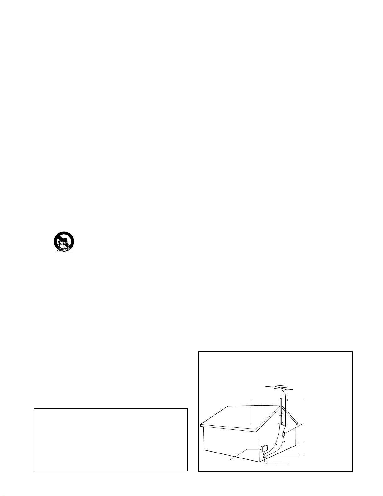
20. Outdoor Antenna Grounding - If an outside antenna is
connected to the receiver, be sure the antenna system is grounded so
as to provide some protection against voltage surges and built up
static charges.
Section 810 of the National Electric Code, ANSI/NFPA No. 70-1984,
provides information with respect to proper grounding of the mast
and supporting structure, grounding of the lead-in wire to an antenna discharge unit, size of grounding connectors, location of antennadischarge unit, connection to grounding electrodes, and requirements
for the grounding electrode. See Figure below.
21. Object and Liquid Entry - Care should be taken so that
objects do not fall and liquids are not spilled into the enclosure
through openings.comply with recommended international global safety
standards for tilt and stability properties of its cabinet design.
22. Battery Usage CAUTION - To prevent battery leakage that
may result in bodily injury, property damage, or damage to the unit:
• Install all batteries correctly, with + and - aligned as marked on
the unit.
• Do not mix batteries (old and new or carbon and alkaline, etc.).
• Remove batteries when the unit is not used for a long time.
Note to the CATV system installer: This
reminder is provided to call the CATV system
installer's attention to Article 820-40 of the NEC
that provides guidelines for proper grounding and, in
particular, specifies that the cable ground shall be
connected to the grounding system of the building,
as close to the point of cable entry as practical.
Example of Antenna Grounding
as per NEC - National Electric Code
GROUND CLAMP
ANTENNA LEAD IN WIRE
ELECTRIC SERVICE EQUIPMENT
ANTENNA DISCHARGE UNIT
(NEC SECTION 810-20)
GROUNDING CONDUCTORS
(NEC SECTION 810-21)
GROUND CLAMPS
POWER SERVICE GROUNDING ELECTRODE SYSTEM
(NEC ART 250, PART H)
4
PANEL LAYOUT
PANEL INDEX
Subject Panel No. (Page No,)
Antenna Basic Connection . . . . . . . . .1 (5)
Audio/Video Connections
AV1 Input Jacks . . . . . . . . . . . . . . . .5 (9)
External Audio System . . . . . . . . . .8 (12)
Front Audio/Video Input Jacks . . . .6 (10)
Headphone Jack . . . . . . . . . . . . . . .6 (10)
Monitor Output Jacks . . . . . .8-9 (12-13)
S-Video Input Jacks . . . . . . . . . . . .7 (11)
AutoLock™ Controls
Access Code . . . . . . . . . . . . . . . . .18 (22)
Block All Channels . . . . . . . . . . .20 (24)
Block Channels . . . . . . . . . . . . . .19 (23)
Clear All Blocked Channels . . . . .20 (24)
Movie Ratings . . . . . . . . . . . . . . .21 (25)
Other Blocking Options . . . . . . . .23 (27)
TV Ratings . . . . . . . . . . . . . . . . . .22 (26)
Understanding AutoLock™ . . . . .17 (21)
Subject Panel No. (Page No.)
AutoPicture™ Control . . . . . . . . . .26 (30)
AutoSound™ Control . . . . . . . . . . .27 (31)
Basic Remote Operation . . . . . . . . . .4 (8)
Basic Television Operation . . . . . . . . .4 (8)
Cable/Cable Box Basic Connection 2-3 (6-7)
Closed Caption Control . . . . . . . . .24 (28)
Factory Service Locations . .30-31 (34-35)
Format Control (4:3 Expand) . . . . .16 (20)
Install Menu Controls . . . . . . . . . . .13 (17)
Limited Warranty . . . . . . . . . . . . . .32 (36)
Onscreen Menu Navigation . . . . . .12 (16)
Picture Menu Controls . . . . . . . . . .14 (18)
QuadraSurf™ . . . . . . . . . . . .28-29 (32-33)
Remote Batteries . . . . . . . . . . . . . . . .4 (8)
Remote Control Button Descriptions
. . . . . . . . . . . . . . . . . . . . . .10-11 (14-15)
Sleeptimer . . . . . . . . . . . . . . . . . . .25 (29)
Sound Menu Controls . . . . . . . . . .15 (19)
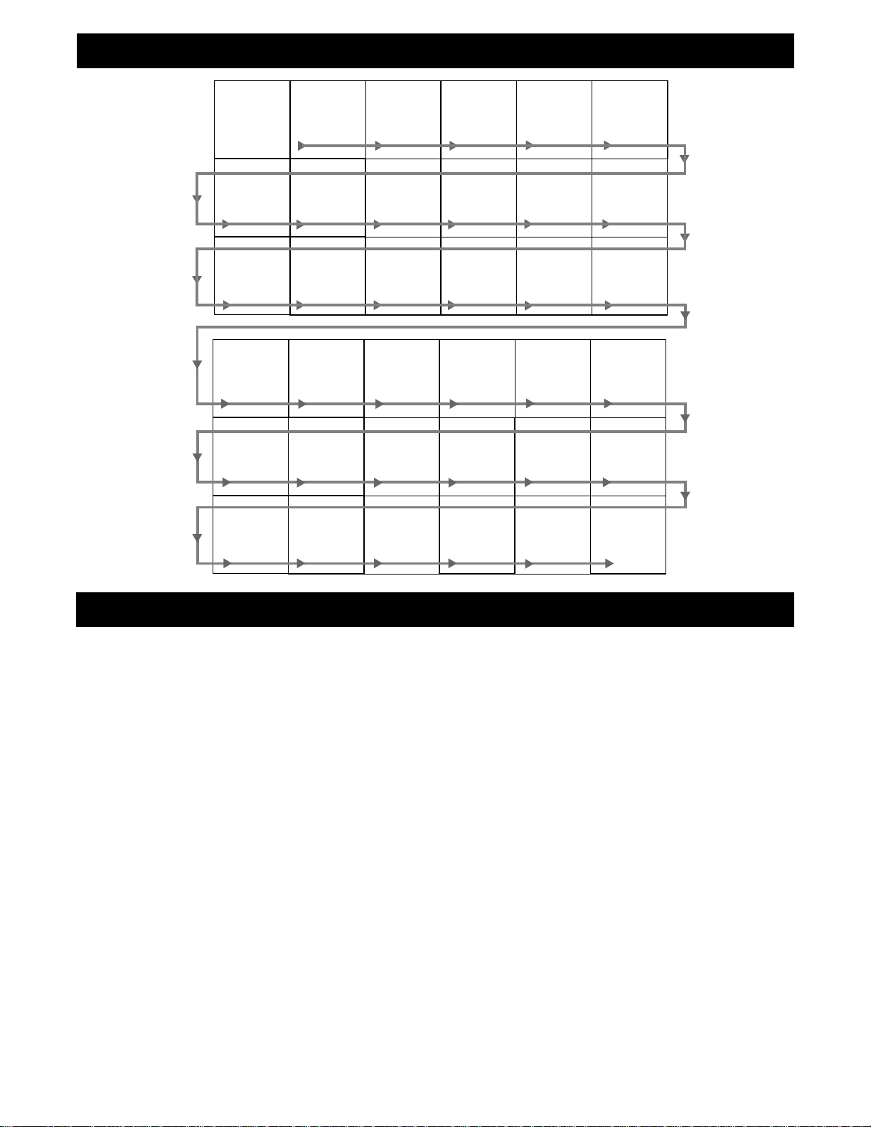
Side 1
Side 2
Panel
Sequence
and
Panel Index
PANEL
3
PANEL
9
PANEL
15
PANEL
21
COVER
PANEL
4
PANEL
10
PANEL
16
PANEL
22
MODEL
REGISTRATION
INFORMATION
PANEL
5
PANEL
11
PANEL
17
PANEL
23
SAFETY
INFO
PANEL
6
PANEL
12
PANEL
18
PANEL
24
PANEL
1
PANEL
7
PANEL
13
PANEL
19
PANEL
25
PANEL
2
PANEL
8
PANEL
14
PANEL
20
PANEL
26
PANEL
27
PANEL
28
PANEL
29
PANEL
30
PANEL
31
PANEL
32
5
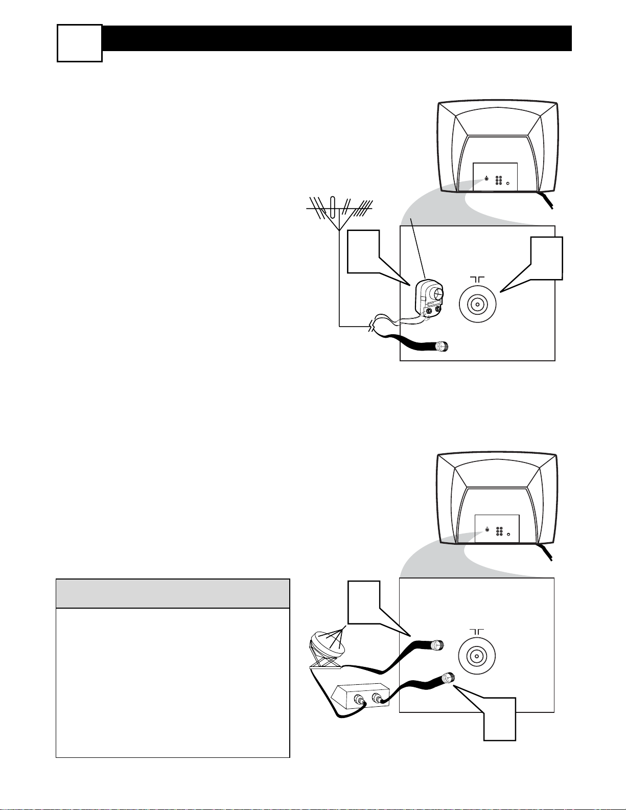
Y
our home’s signal input might come
from a single (75 ohm) round cable, a
Converter Box or from an antenna. In
either case the connection to the TV is
very easy.
1
If your Cable TV signal or
Antenna signal is a round cable
(75 ohm) then you're ready to connect to the TV.
If your antenna has flat twin-lead
wire (300 ohm), you first need to
attach the antenna wires to the
screws on a 300 to 75 ohm adapter.
If you have a Cable Converter
Box: Connect the Cable TV signal
to the Cable Signal IN(put) plug on
the Converter.
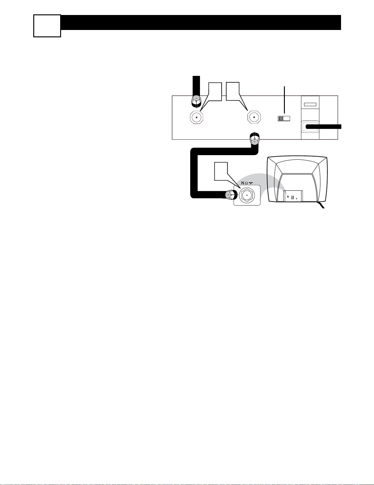
2
Connect the Cable TV cable or
Antenna cable (or 300 to 75 ohm
adapter) to the 75Ω plug on the TV.
If you have a Cable Converter Box:
Connect the OUT(put) plug from the
Converter to the 75Ω plug on the TV.
Be sure to set the TV for the type signal
you've connected (see the “Install Menu
Controls” section of this manual.)
To set the TV to select only the channel
numbers in your area see how to
“Program" or "Add" channels in the
TV’s memory, see the Auto Program
section of this manual.
HELPFUL HINT
Antenna Connection
Cable/Cable Box Connection
300 to 75Ω
Adapter
Combination
VHF/UHF Antenna
(Outdoor or Indoor)
Twin Lead
Wire
Round Cable
75Ω
Round Cable
75Ω
Cable Box
Cable
Company
Signal
Back of TV
Back of TV
BASIC CABLE AND ANTENNA CONNECTIONS
1
1
Monitor
AV1
out
in
75 ⍀
VIDEO
L
AUDIO
R
75 ⍀
S-VIDEO
2
1
IN
OUT
Monitor
out
75 ⍀
VIDEO
L
AUDIO
R
75 ⍀
2
AV1
in
S-VIDEO
6
CABLE BOX CONNECTIONS
I
f you cable signal uses a cable box or
decoder, follow the easy steps below to
complete the connection.
Cable Box (w/RF In/Outputs):
This connection will be mono.
1
Connect the Cable Company supplied cable to
the signal IN(put)
plug on the back of the Cable Box.
2
Using a separate round coaxial cable,
connect one end to the OUT(put)
(TO TV) plug on the back of the
Cable Box.
3
Connect the other end of the round
coaxial cable to the 75Ω input on the
back of the television. Screw it down
finger tight.
NOTE: Set the OUTPUT CHANNEL
SWITCH on the back of the cable box to
CH 3 or 4. Tune the TV to the same channel and change channels at the cable box.
Jack Panel Back of Cable Box
Cable Signal IN
from the Cable
Company
Round 75Ω
Coaxial Cable
Jack Panel Back of TV
Output Channel Switch
2
CABLE
IN
2
4
3
OUTPUT
CH
TO TV
3 4
Monitor
AV1
75 ⍀
out
in
VIDEO
L
S-VIDEO
AUDIO
R
7
CABLE BOX CONNECTIONS
3
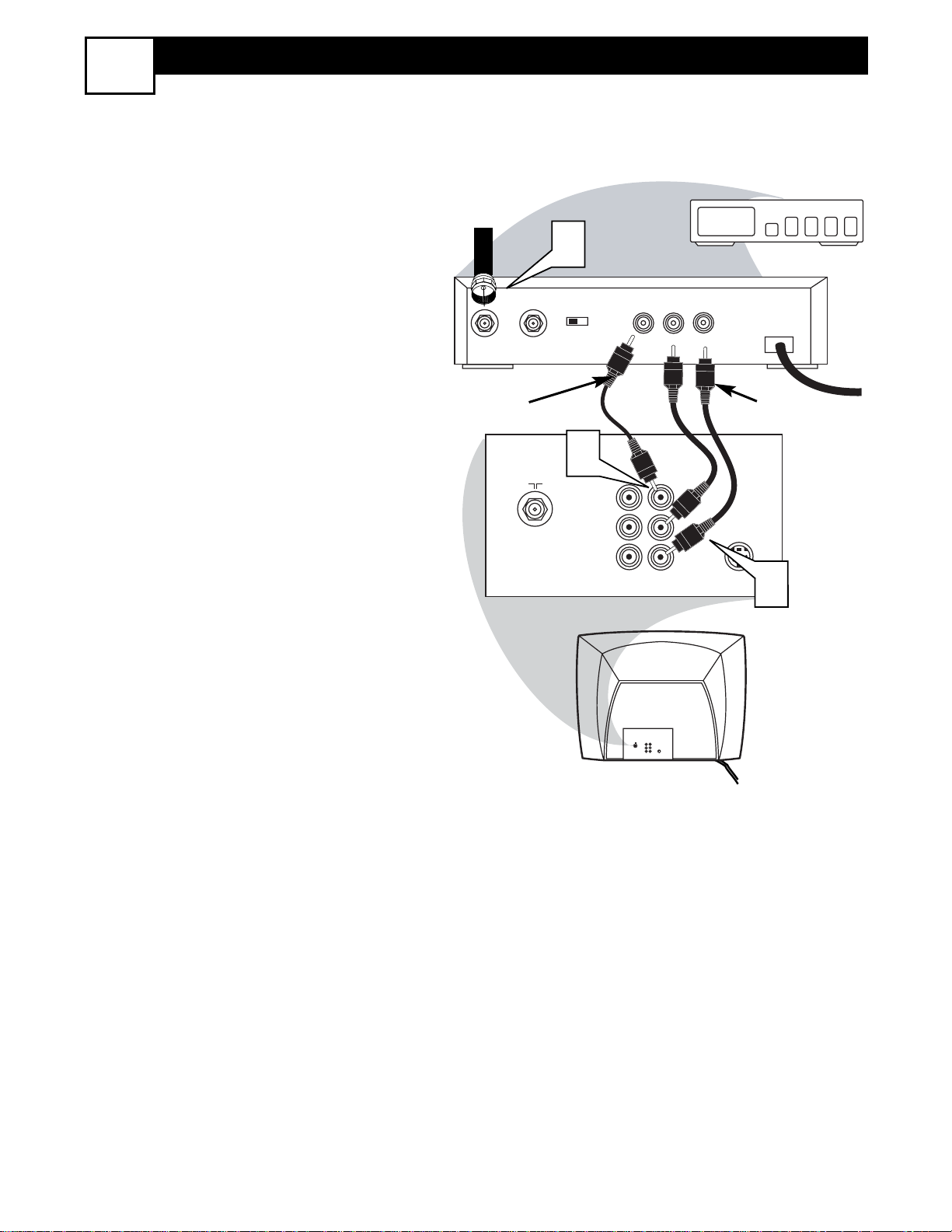
Cable Box (w/Audio/Video Outputs):
This connection will supply Stereo sound.
1
Connect the Cable Company supplied cable to
the cable signal
IN(put) plug on the back of the
Cable Box.
2
Using a RCA type Video Cable, connect one end of the cable to the
Video (or ANT, your cable box may
be labeled differently) Out jack on
the cable box and the other end to the
AV1 Video Input on the TV.
3
Connect one end of the Audio Left
and Right Cable to the left and right
Audio Out L & R jacks on the
cable box. Connect the other end to
the AV1 Audio L & R Input jacks on
the TV.
NOTE: Use the Channel + or – buttons on
the TV remote control to tune to the AV1
channel for the cable box signal. Once
tuned, change channels at the cable box,
not the television.
Cable Signal IN
from the Cable
Company
Cable Box with A/V Outputs
Jack Panel Back of TV
Audio Cables
L& R (Red, White)
Video Cable (Yellow)
CABLE
TO
IN
TV
75 ⍀
1
OUTPUT
CH
3 4
2
Monitor
out
VIDEO
L
AUDIO
R
VIDEO
OUT
AV1
in
LR
AUDIO
OUT
24
S-VIDEO
3
AV1
Monitor
75 ⍀
in
out
VIDEO
L
S-VIDEO
AUDIO
R
8
BASIC TV AND REMOTE OPERATION
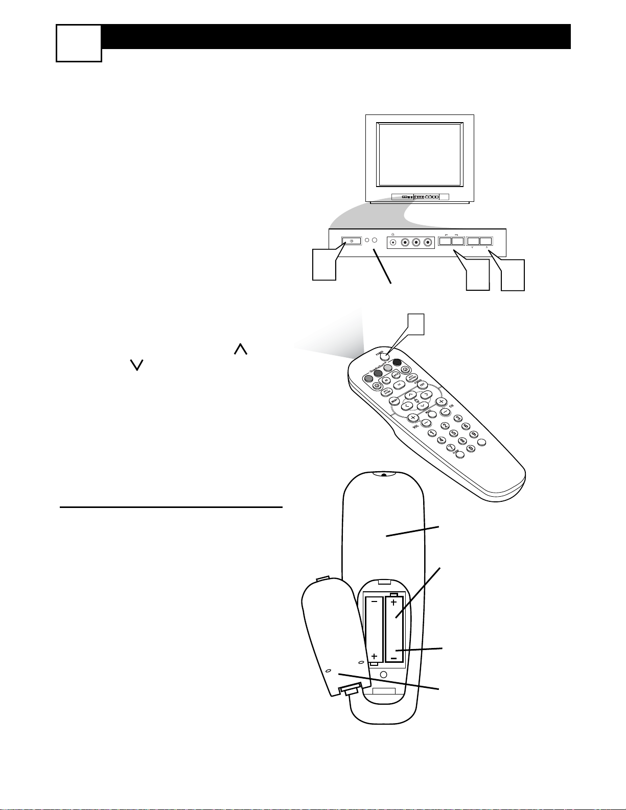
4
1
Press the POWER button to
turn the TV ON.
Note: You can also press any
button on the front of the TV to
turn the TV ON.
2
Press the VOLUME + button to
increase the sound level, or the
VOLUME – button to lower the
sound level.
Pressing both buttons at the same
time will display the on-screen
menu. Once in the menu, use these
button to make adjustments or
selections.
3
Press the CHANNEL UP or
DOWN button to select TV
channels.
REMOTE CONTROL
4
Point the remote control
toward the remote sensor window on the TV when operating
the TV with the remote.
T
o load the supplied batteries into the
remote:
1. Remove the battery compartment
lid on the back of the remote.
2. Place the batteries (2-AA) in the
remote. Be sure the (+) and (-) ends of
the batteries line up correctly (inside of
case is marked.)
3. Reattach the battery lid.
– VOLUME +
CHANNEL
MENU
– VOLUME +
CHANNEL
MENU
AUDIOVIDEO L R
AUDIO
VIDEO
L
R
1
2
3
Battery Compartment
2-AA Batteries
Battery Lid
Back of Remote
Remote
Sensor Window
Front of TV
1
VOL
9
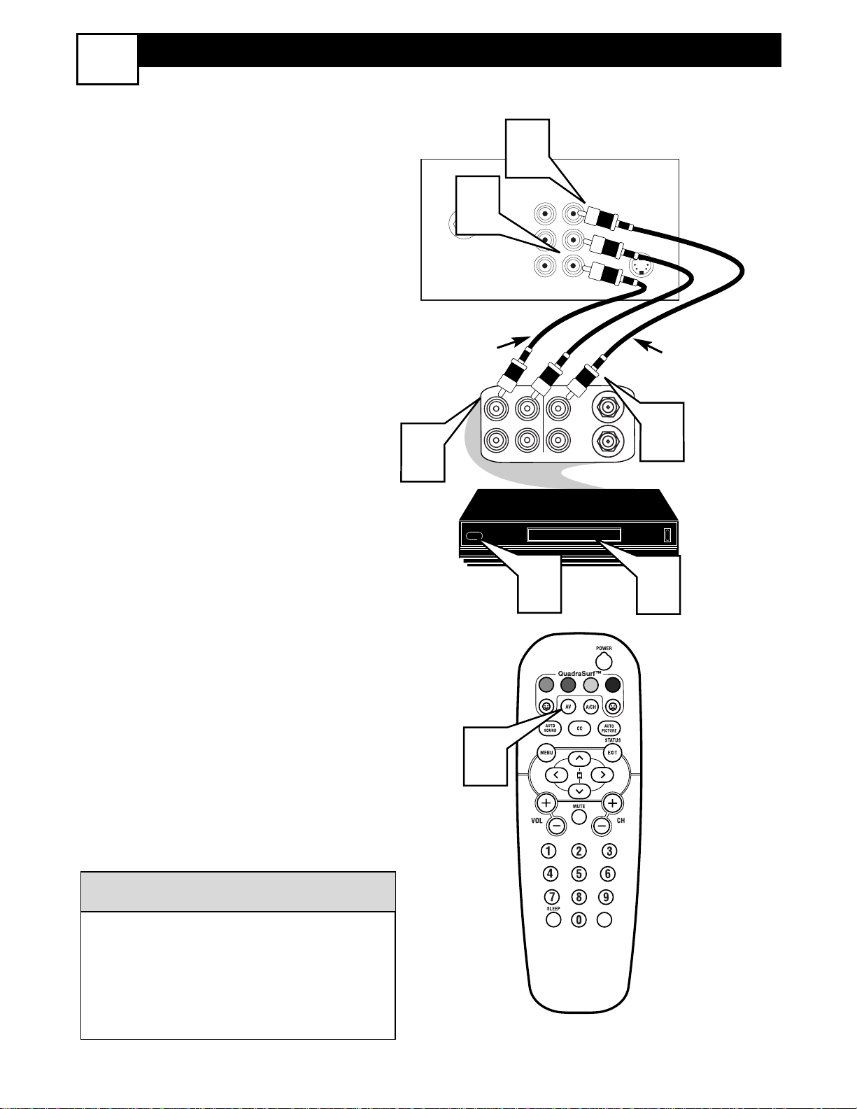
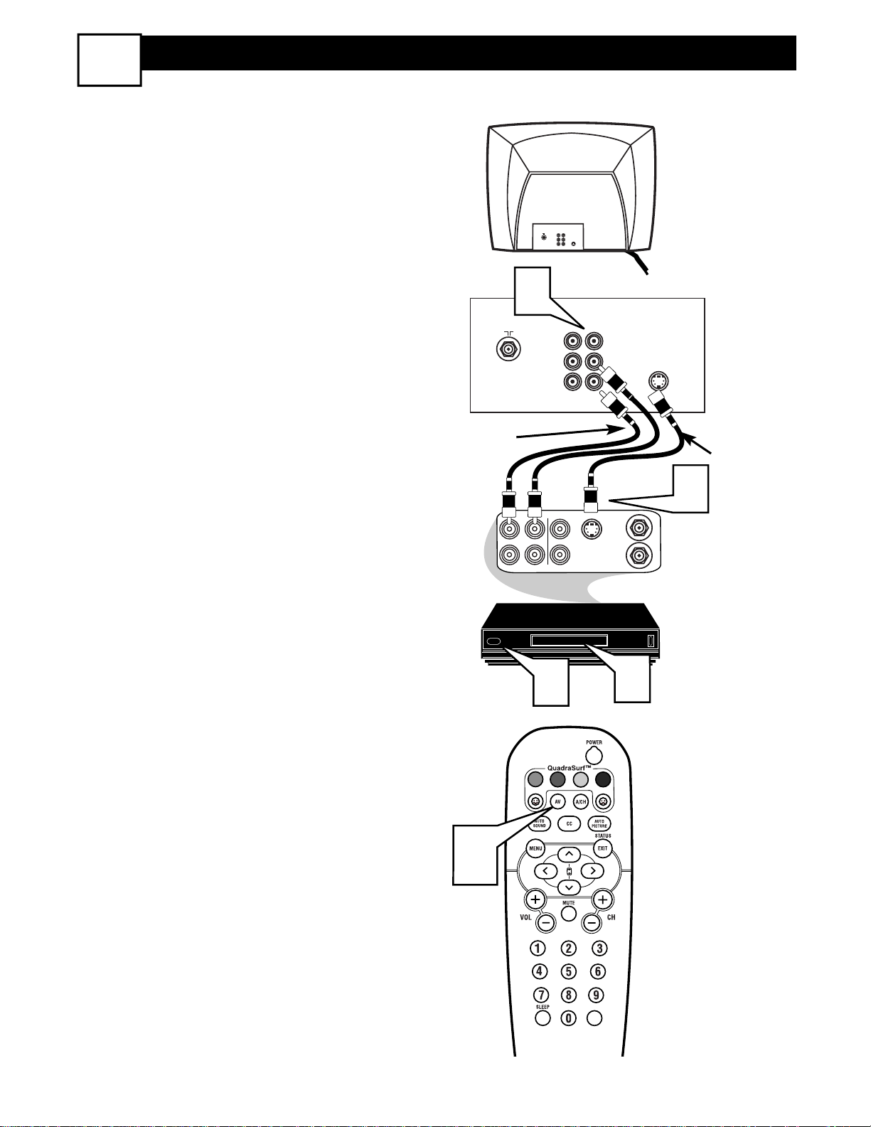
AV1 AUDIO/VIDEO INPUT CONNECTION
5
T
he TV’s audio/video input jacks are for
direct picture and sound connections
between the TV and a VCR (or similar
device) that has audio/video output jacks.
Follow the easy steps below to connect an
accessory device to the AV 1 Input Jacks
located on the back of the TV.
1
Connect the VIDEO (yellow) cable
to the VIDEO AV1 in jack on the back
of the TV.
2
Connect the AUDIO (red and white)
cables to the AUDIO (left and right)
AV1 in jacks on the rear of the TV.
3
Connect the VIDEO (yellow) cable
to the VIDEO OUT jack on the back
of the VCR.
4
Connect the AUDIO (red and white)
cables to the AUDIO (left and right)
OUT jacks on the rear of the VCR.
5
Turn the VCR (accessory device)
and the TV ON.
6
Press the AV button on the remote
control to select the AV1 channel. AV1
will appear in the upper left corner on
the TV screen.
7
With the VCR (or accessory device)
ON and a prerecorded tape (CD,
DVD, etc.) inserted, press the PLAY
button to view the tape on the tele-
vision.
All the AV channels can be selected by
pressing the Channel + or – buttons.
The AV channels can also be added to
the QuadraSurf™ buttons for quick
access.
HELPFUL HINT
Video Cable
(Yellow)
Audio Cables
(Red & White)
Back of TV
Back of Typical VCR
VCR with
Audio/Video Outputs
4
75 ⍀
2
1
AUDIO
IN
Monitor
AV1
out
in
VIDEO
L
AUDIO
R
ANTENNA
OUTOUT
VIDEO
LR
ANTENNA
IN
S-VIDEO
IN
OUT
3
6
5
VOL
7
10
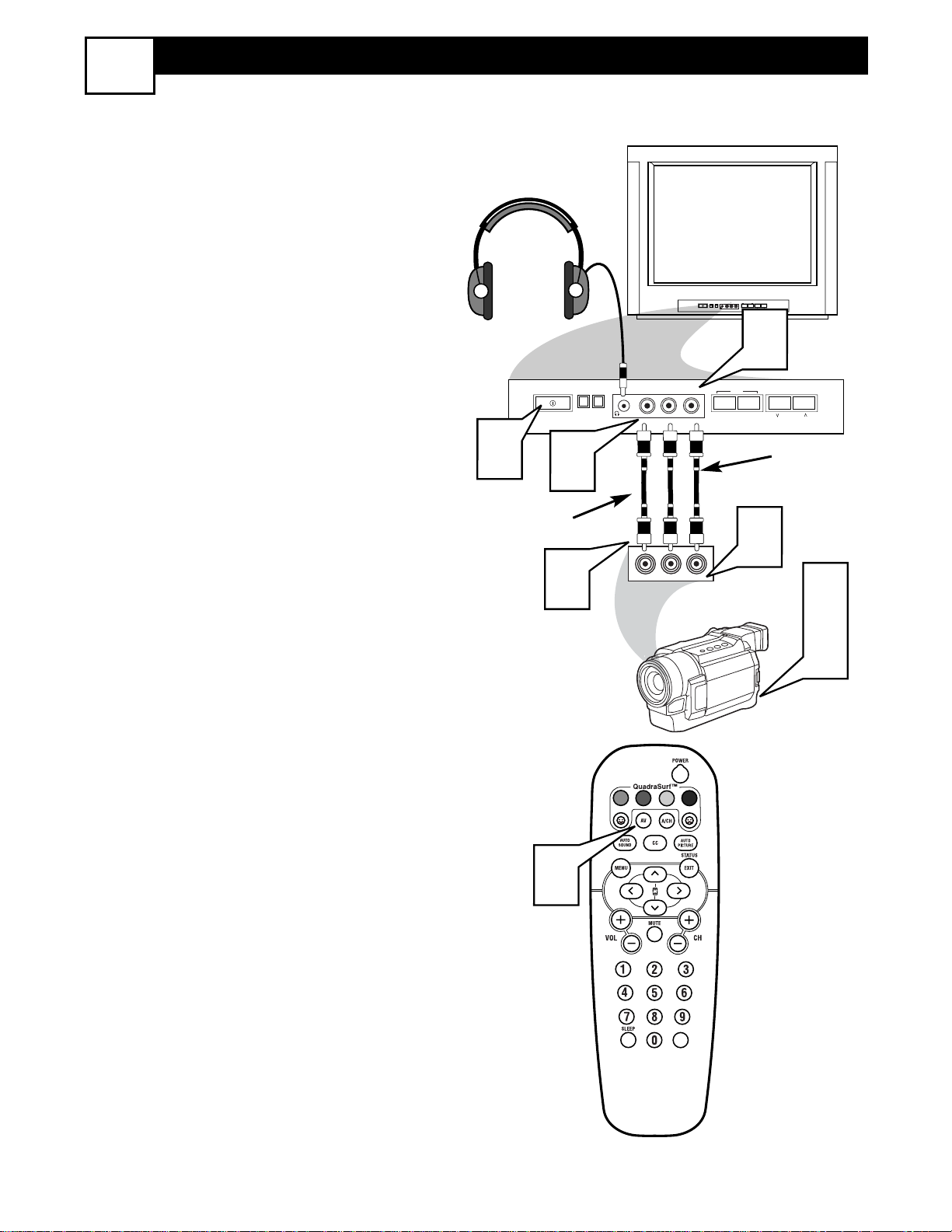
FRONT AUDIO/VIDEO INPUT CONNECTION
6
T
he TV also has Audio/Video Input Jacks
located on the front of the TV cabinet
for easy and quick connections that might
not be permanent. This type of connection
might be useful for the playback of a tape
from a camera or a video gaming device.
Follow the easy steps below to connect an
accessory device to the Front Input Jacks.
1
Connect the VIDEO (yellow) cable
to the VIDEO in jack on the front of
the TV.
2
Connect the AUDIO (red and
white) cables to the AUDIO (left
and right) in jacks on the front of the
TV.
3
Connect the VIDEO (yellow) cable
to the VIDEO OUT jack on the back
of the camera (or accessory device).
4
Connect the AUDIO (red and
white) cables to the AUDIO (left
and right) OUT jacks on the rear of
the camera (or accessory device).
5
Turn the camera (or accessory
device) and the TV ON.
6
Press the AV button on the remote
control to select the FRONT channel. FRONT will appear in the upper
left corner on the TV screen.
7
With the camera (or accessory
device) ON and a prerecorded tape
(CD, DVD, Game Card, etc.,
depending on type of accessory
device) inserted, press the PLAY
button to view the tape on the
television.
Video Cable
(Yellow)
Audio Cables
(Red & White)
Headphone Jack
(will Mute the TV
speakers when in use)
Front Control Panel
External Accessory Device
(with Audio/Video Outputs)
5
3
1
VIDEO L R
AUDIO
VIDEO
AUDIO
INSTALL/MENU
VIDEO L R
AUDIO
– VOLUME +
2
MENU
– VOLUME +
4
RL
CHANNEL
CHANNEL
5
6
7
VOL
11
S-VIDEO INPUT CONNECTION
T
he S(uper)-Video connection on the
rear of the TV can provide you with
better picture detail and clarity for the
playback of accessory sources such as
DBS (digital broadcast satellite), DVD
(digital video discs), video games, and
S-VHS VCR (video cassette recorder)
tapes than the normal antenna picture
connections.
NOTE: The accessory device must
have an S-VIDEO OUT(put) jack in
order for you to complete the connection on this page.
1
Connect one end of the S-VIDEO
CABLE to the S-VIDEO jack on
the back of the TV. Then connect
one end the AUDIO (red and
white) CABLES to the AV1 in
AUDIO L and R(left and right)
jacks on the rear of the TV.
2
Connect other end of the SVIDEO CABLE to the S-VHS
(S-Video) OUT jack on the back
of the VCR. Then connect the
other ends of the AUDIO (red and
white) CABLES to the AUDIO
(left and right) OUT jacks on the
rear of the VCR.
3
Turn the VCR and the TV ON.
4
Press the AV button on the
remote to scroll the channels until
SVHS appears in the upper left
corner of the TV screen.
5
Now your ready to place a prerecorded video tape in the VCR and
press the PLAY button
.
VCR or External
Accessory Device
(with S-Video Output)
Audio Cables
(Red & White)
S-Video
Cable
Back of TV
7
75 ⍀
1
AUDIO
IN
Monitor
AV1
out
in
75 ⍀
VIDEO
L
S-VIDEO
AUDIO
R
AV
Monitor
in
out
VIDEO
AUDIO
L
R
S-VIDEO
2
OUTOUT
S-VHS OUT
VIDEO
LR
IN
ANTENNA
ANTENNA
IN
OUT
3
5
4
VOL
 Loading...