

Page 1
.{•••'•3k
€
-912/01
-
912/02
Semi-automatic
Bobbin
Winder
Provisional
and
Service
Instruction
Manual
Book
'Vi
G.
M.
PFAFF
AG
K
AIS
ERS
LA
U TE RN
BRANCH
Printed in Germany
Page 2
1.
1.1
Instructions
Winding
the
First
Bobbin
1.2
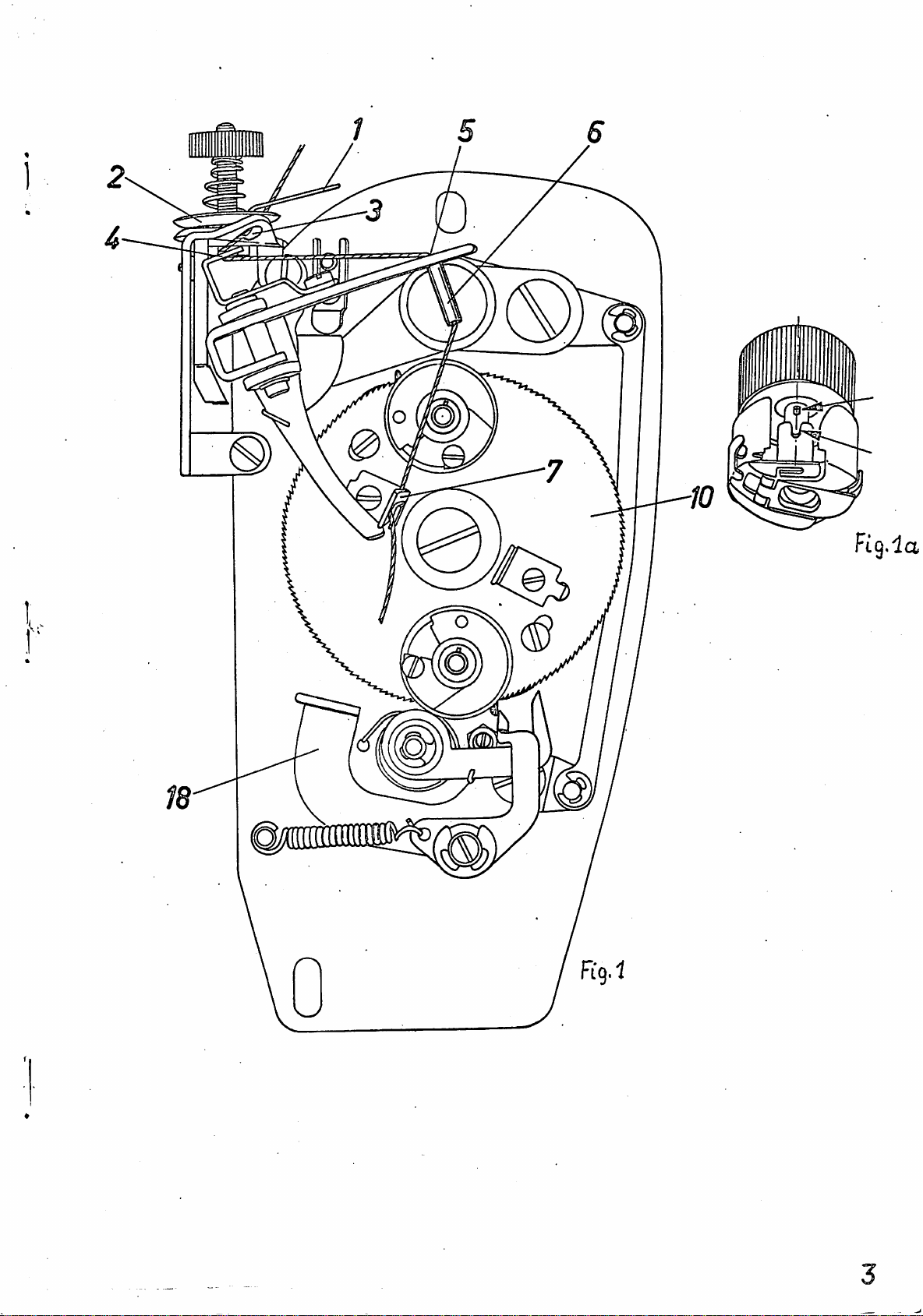
Thread
thread
the
empty
that
arrows
place
Depress
thread
out
.
Cut
off
over
after
time).
bobbin.
The
bobbin
sewing.
by
half
the
bobbin
ceive
Bobbin
Take
sewing
spindle.
bobbin
winder
cally
stitches
truding
case
with
the
guides
the
in
on
guide
knife
the
The
the
Changing
the
hook
case
spindle.
cut
bobbin
bobbin
key
Fig.
the
starting
the
protruding
?.
bobbin
bobbin
is
When
a
turn
case.
next
bobbin
and
Depress
with
to
of
the
on
the
the
1-6
enters
la)
spindle.
tube
(The
wound
the
and,
bobbin
case
place
As
the
next
back
full
winder
(Fig.
on
the
the
and
lever
6_
is
thread
winder
winder
automatically
bobbin
while
The
bobbin
with
starting
the
full
3'"ou
proper
seam.
Of
bobbin
by
upper
slot
that
2^
lowered
thread
has
is
is
case.
it
on
do
length
the
leading
l).
the
(FiS-
has
been
now
full,
doing
winder
the
the
lever
bobbin
this,
Teai-
bobbin
in
Push
bobbin
in
into
end
to
ready
empty
upper
required
off
the
the
the
the
bobbin
bobbin
1)•
As
the
by
be
cut
threaded
while
gear
so,
automatically
is
bobbin
1_8
(Fig.
from
the
thread
the
and
sewing
thread
bobbin
winder
case
you
bobbin
pulling
off
for
the
wheel
now
bobbin
the
for
thread
insert
hook.
spindle
case
snaps
do
by
for
winding
machine
1Q
ready
out
winder
1)
and
lower
is
the
the
through
case
(see
this,
case
the
hand
the
rotates
to
of
pull
bobbin
automati
starting
end
bobbin
with
so
into
cut
thread
only
fii'st
the
is
threads
re
the
the
pro
Page 3
4
s
Fig.-la
m
s
Page 4
2.
2.1
Ad.lustments
Ad.justing
the
Gear
Wheel
Rotating
Lever
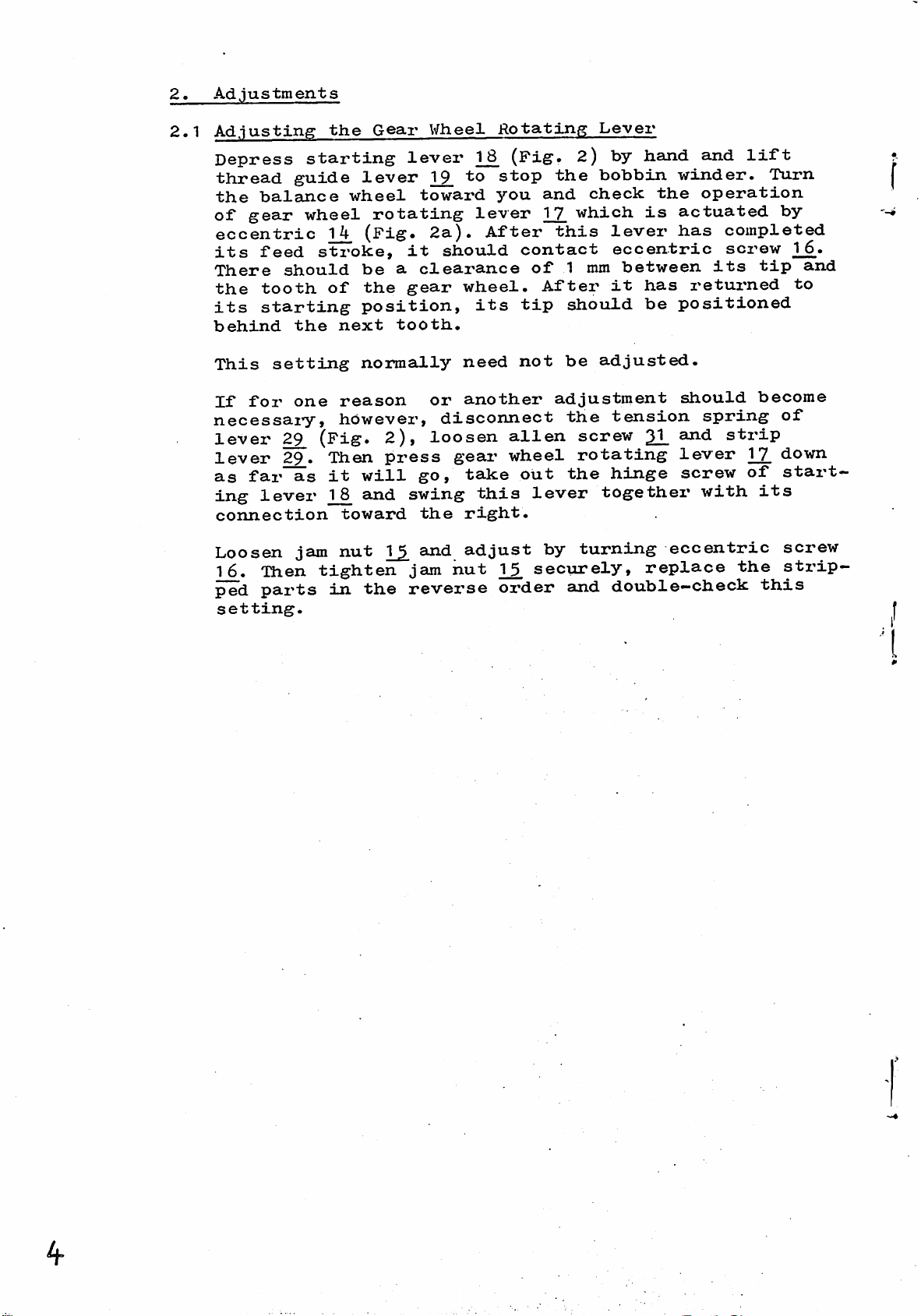
Depress
thread
the
of
gear
eccentric
its
There
the
its
behind
This
If
necessai-y,
level'
lever
as
ing
connection
Loosen
16.
ped
setting.
balance
feed
should
tooth
starting
setting
for
29_
29^.
far
lever
Then
parts
guide
the
one
as
jam
starting
wheel
wheel
14
stroke,
of
next
reason
however,
(Pig.
Then
it
1_8
toward
nut
tighten
in
lever
lever
towai-d
rotating
(Pig.
it
be
a
clearance
the
gear
position,
tooth.
normally
2),
press
will
and
the
go,
swing
1^
jam
revei'se
the
and
^8
1_2.
to
you
lever
2a).
After
should
wheel.
its
need
or
another
disconnect
loosen
gear
take
this
right.
adjust
nut
(Pig.
stop
contact
of
tip
not
alien
wheel
out
lever
securely,
oz'der
2)
the
and
1_7
check
which
this
1 mm
After
should
be
adjustment
the
screw
rotating
the
by
turning
and
by
hand
bobbin
is
lever
winder.
the
actuated
has
and
operation
eccentric
between
it
has
returned
be
positioned
adjusted.
should
tension
spring
2L
lever
hinge
together
screw
with
eccentric
replace
double—check
lift
Turn
completed
screw
its
tip
become
strip
1J7
of
its
the
this
by
16.
and
to
of
down
start
screw
sti'ip-
4*
Page 5
15 15
Ca 1 mm
16 17
2 a.
Page 6
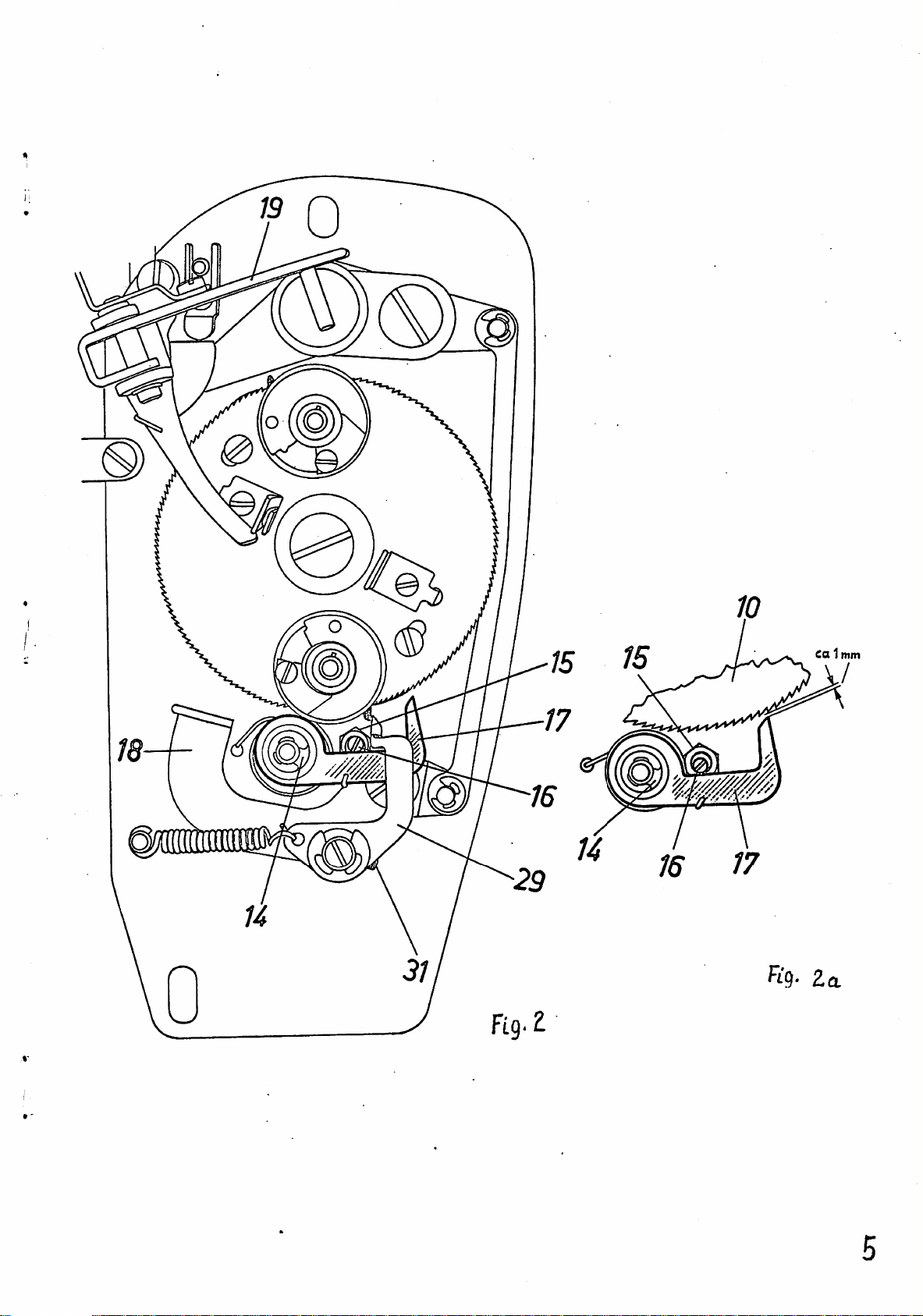
2.2
Adjusting
tlie
Positioning
Lever
Depress
guide
machine
bobbin
zontal
tioning
10
(see
If
adjustment
and
turn
tioning
Tighten
starting
level'
and
winder
line.
lever
arrow
eccentric
lever
alien
T_2^
let
spindles
Now
29_
in
is
22_
screw
lever
stop
gear
check
is
Fig.
requii'ed,
stud
at
wheel
flush
the
21.
the
2.
to
3a).
2^
correct
securely
(Fig.
bobbin
1_0
see
with
loosen
3)
x^rinder.
rotate
positioned
that
the
rim
alien
height
again.
and
the
until
lift
in
tip
of
screw
(Fig.
Start
the
a
of
gear
thread
the
two
hori
posi
wheel
31
posi
3a).
Page 7

(D
0
GD
s
r £
-Sy
L
Page 8

2.3
Adjusting
the
Stopping
of
the
Gear
\^^t^eel
Check
protrude
.
1^.
stop
tighten
Stax't
the
tating
wheel
position
thread
stopped
tube
winder
If
move
winder
make
stop
Move
winder
too
to
see
about
To
adjust,
tripping
screws
the
bobbin
lever
10.)
of
guide
coi^rectly,
6
should
spindle
adjustment
stop
sto-jps
sure
tripping
the
tz^ipping
stops
late.
that
points
machine
winder
1_7
Depress
bobbin
tube
be
is
tripping
correctly.
you
do
point
too
the
1
mm
loosen
2&_
securely.
and
stops
no
6
in
9,»
required,
not
point
eai'ly,
two
beyond
set
as
let
longer
starting
winder
(Fig.
the
left
line
point
disturb
27.
as
stop
sci^ew
shown
gear
the
tripping
teeth
2^
in
wheel
Fig.
automatically.
engages
lever
spindle
4).
If
edge
with
of
the
loosen
27.
sideways
As
you
make
the
to
or
shown
the
to
in
left
the
and
the
1^
9,
in-
the
bobbin
thread
center
set
until
this
vertical
Fig.
if
i-ight,
of
adjust
4a.
1_0_
(Gear
teeth
and
relation
screw
the
points
gear
wheel
Then
rotate
wheel
of
check
winder
guide
of
bobbin
2^
the
adjustment,
setting
4a.
bobbin
if
it
27
the
until
ro
gear
the
to
has
and
bobbin
of
stops
Check
in
the
the
same
position
manner
of
and
the
adjust,
other
bobbin
if
winder
necessai'y.
spindle
5
Page 9

iT
6^
d
Page 10

2,4
Ad
.jus
ting
the
Bobbin
i/inder
Spindles
\\rhen
bobbin
at
the
line
If
adjustment
the
upper
key
enters
Fig.
thread
gear
5a)
of
easily
Loosen
bobbin
winder
the
bobbin
spindle
depx'ess
19.
Let
be
tightened
make
does
the
bobbin
winder
top
(dash-dot
bobbin
la.
Depress
guide
wheel
pinion
accessible.
both
winder
until
is
starting
gear
sure
not
that
exceed
and
the
H)
alien
case
at
spindle
slightly
line
is
slot
lever
rotate
3^
spindle
the
the
wheel
again.
the
winder
i^equired,
winder
starting
1_2.
on
screws
bobbin
until
position
lever
10
end
0.1
in
in
until
the
As
mm.
has
(Fig.
Fig.
the
"to
can
case
the
1_8
turn
you
play
stopped,
to
the
place
spindle,
bobbin
lever
stop
both
back
2^
be
key
indicated
and
until
tighten
5)
5)«
of
jast
turned.
is
of
should
right
1_8_
the
alien
gear
at
on
lift
the
key
a
bobbin
making
case,
(Fig.
bobbin
lightly
the
the
thread
both
the
bobbin
be
of
the
sure
as
sci'ews
wheel
Run
top.
bobbin
above.
screws
two
on
the
positioned
vertical
case
5)
on
that
shown
and
winder.
3^
1_0
are
so
that
the
bobbin
When
winder
Again
guide
3^
alien
winder
the
in
lift
Let
(Fig.
the
rotate
lever
oan
screws,
spindle
To
guide
wheel
press
that
cutout.
Check
and,
check,
lever
turn
down
thread
the
if
depress
1_2,
until
starting
guide
other
necessary,
to
bobbin
starting
stop
the
lever
tube
auijust.
the
bobbin
^
windez'
lever
bobbin
is
case
is
and
centered
spindle
1_8
and
winder.
at
check
in
in
the
to
lift
the
the
Let
top.
make
bobbin
thi'ead
the
Then
sure
same
gear
case
manner
-10
Page 11

9
s
Page 12

2.5
Ad.justing
the
Amount
of
Thread
on
the
Bobbin
Place
bin
6)
Check
Thread
when
,
positioned
case
To
thread
bin.
21
wrench
Turn
thr
Tighten
tighten
and
a
winder
and
to
the
(Fig.
adjust,
Loosen
upwards
this
ead.
this
bobbin
slowly
see
guide
lower
guide
(see
segment
the
them
might
case
spindle.
lift
when
lever
about
6).
again
lever
the
or
downwai'ds
arrow
alien
too
cause
this
end
1
depress
lower
in
up
screws,
much
with
Depress
thread
J[_9,
should
of
mm
inside
1_9,
down
alien
Fig.
for
as
heavy
an
guide
lever
thread
starting
with
6).
more
but
they
empty
starting
stops
stop
guide
cutout
onto
screw
a
hexagon
thread,
make
press
working.
bobbin
lever
the
lever
the
2^
levei'
1_2_byhand.
the
bobbin
bobbin
tube
2^
of
core
and
socket
or
sure
on
you
a
hollow
on
^
the
and
of
turn
down
the
18
is
the
do
bob
(Pig,
winder.
winder
still
bobbin
push
bob
segment
screw
for
not
shaft
less
(g
Fig.
6
Page 13

2.6
Inopei'ative
Position
of
Thread
Guide
Lever
When
be
thread
(Pig.
To
the
this
the
a
clearance
guide
7).
adjust,
latter
adjustment,
bobbin
loosen
higher
tube
winder
of
4-5
6
and
the
or
tighten
is
mm
set
lower,
inoperative,
between
the
screw
the
rim
as
appropriate.
set
the
of
of
screw
the
stop
there
lower
gear
securely.
2^
end
wheel
and
After
should
of
set
Fig.
mm
7
-15
Page 14

2.7
Ad.justinff
When
should
and
If
the
adjustment
spring
as
may
clearance.
thread
be
left
suspension
be
Lever
guide
a
clearance
knife
required
Tighten
is
12
levei'
7.
required,
screw
to
both
19_
of
2^
obtain
screws
1-2
is
inopei'ative,
mm
8)*
loosen
and
the
between
stop
tui^n
securely.
the
above-mentioned
lever
screw
set
there
26
collar
12
and
Note
bound
that
to
screws
cause
which
heavy
0
are
working.
tightened
too
much
are
Page 15

2.8
Setting
the
Thread
Guide
Lever
to
the
Bobbin
\\nierL
inclined
this
flush
in
Fig.
If
it
adjust
inaJcing
the
left
thread
toward
position,
with
9a-)*
is
not,
the
sure
side
guide
the
the
rear
loosen
position
that
of
base
the
fork
lever
rear
wall
of
plate
set
thread,
prong
32*
1_9.
edge
of
screw
i%
inoperative,
13*
of
the
guide
of
bracket
i^Tith
tube
bobbin
^3.
lever
^
(Fig.
lever
should
(see
9)»
3iL
it
1_2,
in
arrow
s^nd
29.
while
contacts
is
be
Fig.
Fig.
9
9a
Page 16

2.9
Adjusting
Remove
ing
lever
(Fig.
about
winder
bobbin
10)
5 mm
spindle
the
1_8
by
hand
between
Leaf
case
(Fig.
9.*
Spi'ing
with
5).
until
thread
bobbin
Lift
there
thread
guide
is
and
a
tube
depress
guide
clearance
6
and
start
lever
bobbin
]_2.
of
When
not
at
wider
press
To
from
flat
set
in
be
its
than
thread
adjust,
the
spring
screw
this
engaged
forward
5 mm,
loosen
inside
38
position,
by
point
guide
37
to
securely.
of
leaf
leaf
set
the
of
lever
the
thread
spring
revei'sal.
spring
^2.
screw
tension
correct
guide
37,
27.
2^
position.
i.e.
If
should
rear.
which
bracket
lever
the
can
is
start
aind
Then
1_2.
should
gap
be
must
be
grows
to
reached
swing
tighten
Fig.
i
10
^6
Page 17

Final
Inspection
of
Bobbin
Winder
Start
it
(Fig.
guide
of
If
ed
second
Thread
and
upper
l8
bobbin
chine
If
adjust
check
winder
Now
stops
the
it
in
place
and
the
the
the
machine
automatically.
5)
and
tube
is
par.
bobbin
not,
bobbin
the
6^
2.3
bobbin
a
bobbin
bobbin
start
and
stop.
speed
bobbin
the
the
cover.
bobbin
shortly
segment
following
check
is
positioned
winder
readjust
above.
winder
winder
the
is
winder
and
let
whether
spindle.
Make
spindle.
winder
case
spindle.
machine.
It
is
before
either
as
instructed
adjustments
is
the
bobbin
Depress
the
exactly
the
bobbin
the
as
instructed
with
recommended
too
an
Depi'ess
Watch
the
full
ready
starting
left
winder
same
anpty
the
bobbin
or
in
and
for
winder
edge
above
check
in
bobbin
starting
machine
to
reduce
is
not
par.
replace
operation.
lever
of
the
as
full.
full
2.5»
run
thread
center
insti'uc.t-
for
par.
on
wind
the
enough,
the
until
T_8
the
1.1
the
lever
the
ma
Double-
bobbin
^7
 Loading...