

Page 1
PFAFF
335
Instruction
manual
296-12-17
Betriebsanleitung engl. 8.96
599
Page 2
This Instruction manual is validfor all models and subclasses listed in the
chapter„Specifications".
The reprinting, copying or translation of
part, is only
source.
G.M.
PFAFF
permitted
with
our
previous
PFAFF
Instruction Manuals,
permission
and
with
written
whether
referencetothe
Aktiengeselischaft
Postfach
D -
Konigstr.
D -
67653
67655
3020
Kaiserslautern
154
Kaiserslautern
Editing/Illustrations
Verlag
D-77901
-TD
Lahr
inwhole or in
Page 3
Contents
1 Safety
1.01 Directives 1
1.02 General
1.03 Safety symbols
1.04 Important points for
1.05 Operating and specialist personnel 1 - 3
1.05.01 Operating personnel 1 - 3
1.05.02 Specialist personnel 1 - 4
1.06 Danger symbols 1 - 5
2
3 Specifications
3.01
3.02
4 Disposal of
Proper
PFAFF335
Possible
notesonsafety
the
use
models
the
and
machine
user 1 - 3
subclasses
1-1
-1
1
-1
1-2
2-1
3-1
3-1
3-1
4-1
5 Transport, packaging
5.01 Transportto the customer's premises 5 -1
5.02 Transport
5.03 Disposal of the packaging 5 -1
within
and
storage
5
-1
the customer's premises 5 -1
5.04 Storage 5 -1
6 Explanation of the symbols
7 Operational controls
7.01
7.02 Pedal
7.03
7.04
On/Offswitch 7 -1
Stitch-length adjustmentlever/reverse sewing
Adjustment nutforthe top feed
8 Mountingand initial operation
8.01
Mounting
lift
6-1
7-1
7-1
7-2
7-3
8-1
8-1
8.01.01
8.01.02
8.01.03
8.01.04
PFAFF
Adjusting
Tightening
Mounting
Mounting
the
the
the
the
table
V-belt
upper
lower
height
V-belt
V-belt
guard
guard
8-1
8-2
8-3
8-3
Page 4
Contents
8.01.05
8.01.06
8.02
8.03 Switching the machineon/off
9 Preparation
9.01 Needle
9.02 Inserting the needle
9.03
Mounting
Mounting
Initial
operation
and
Winding
the sewing
lamp
the spoolholder
thread 9
the
bobbin
thread, adjusting the thread tension 9 - 2
8-4
8-4
8-4
8-4
9-1
-1
9-2
9.04 Removing the bobbincase, threading the bobbincase 9 - 3
9.05 Insertingthe bobbin case, adjusting the bobbinthread tension
9.06
Threading the needle thread
9.07 Adjusting the needle thread tension
0
0.01 Servicing intervals
Care
and
maintenance
9-3
9-4
9-4
10-1
10-1
0.02
0.03
0.04
0.05 Lubricating
0.06
Cleaning
General
Lubricating
Checking
lubrication
the
sewing
the
hook
the
air pressure
head
0.07 Emptying/ Cleaning the water container of
1
1.01
1.02 Notes on adjusting
1.03
1.04 Adjusting
1.04.01 Positioning
1.04.01.01
Adjustment
Tools, gauges and otheradjustment accessories
Abbreviations
the
basic machine
the
feed dog
Lateral positioning of
the
feed dog
1.04.01.02 Lengthwise positioning of the feed dog
1.04.02 Centering
the
needle in
the
needle hole
the
airfilter
10-1
10-2
10-3
10-3
10-4
10-4
11-1
11-1
11-1
11-1
11-2
11-2
11-2
11-3
11-4
1.04.03 Pre-adjusting
1.04.04
1.04.05 Needle rise, hook-to-needle clearance and needle height
1.04.06
Driving
Vibrating
the
needle height
motion of the top and bottom feed dogs
presserfeeding motion
1.04.07 Vibrating presser lift
11-5
11-6
11-7
11-8
11-9
PFAFF
Page 5
Contents
1.04.08
Needle
thread
tension
release
1.04.09 Thread check spring
1.04.10
1.04.11
1.05 Adjusting
1.05.01
1.05.02
Bobbin
winder
Regulatingthe pressure on the presserfoot..
the
Preadjusting
Tripping
lever height
thread
the
trimmer
control cam
-800/52
1.05.03 Feed regulator pin
1.05.04 Engagingsolenoid
1.05.05 Adjustingthe height of the feed regulator pin.
1.05.06 Thread catcher, front point of reversal
1.05.07 Lateral adjustment of
the
thread catcher
1.05.08 Control cam, finaladjustment
1.05.09
1.05.10 Triggering
1.05.11
Knife
Cutting
the
needle thread tension
test
1-10
1-11
1-12
1-13
1-14
1-14
1-15
1-16
1-17
1-18
1-18
1-20
1-21
1-22
1-23
1-24
1.05.12
Positioner
1-25
PFAFF
Page 6

Safety
Safety
1.01
1.02
Directives
This
machineisconstructedinaccordance
conformity
and
manufacturer's
declarations.
Inaddition to this Instruction Manual,
other
regulations
mental
The
other
protection
regionally valid regulations of
supervisory
General
•
This
machine
completely
•
All
Notes
before
operating
notes
read
on Safety
and
legal
requirements
regulations!
the
organisations
on
safety
may
onlybeoperatedbyadequately
and
understood
and
the
machine.
aretobe
Instruction Manuals of
with
the
observe
social
the
also all generally
-including
insurance
strictly
Instruction Manual.
adhered
European regulations
accepted,
thoseofthe
society
trained
the
motor
country
for occupational
to!
operators
manufacturer
containedinthe
statutory
and
all valid environ
accidents
and
only
after
aretobe
and
or
having
read
• This machine may onlybeused
operated
be
•
When
bobbin),
maintenance
off
• Everyday
• Repairs
or
appropriately
•
When
removed
and
• Work on electrical
without
adhered
exchanging
when
the
On/Off switch or by removing
maintenance
and
servicing or carrying
from
function
to.
threading
work,
special
trained
the
checks
its
safety
sewing
tools (e.g. needle,
the
the
machine is to be
work is only to be carried
maintenance
personnel.
compressed
carried
equipment
devices.
machine,
out
out
for
the
All
when
the
work
repairs on
air supply.
purpose
safety
separated
may
for which it is
regulations relevant to its
presser
leaving
plug from
onlybecarried
pneumatic
The
foot, needle plate,
the
machine
from
the
the
mains.
out
by appropriately trained personnel.
out
devices,
only
exceptions
intended
unattended
power
by qualified
the
machineisto
to this
and may
operation
feed
dog
and
not
are
or
during
be
supply by switching
service
are
adjustments
staff
be
to
by appropriately trained personnel.
may onlybecarried out by appropriately trained personnel.
• Work is not permitted on parts and
supply. Exceptions to this
1
-1
are
equipment
in accordance with
which
are
connectedtothe
the
regulations EN 50110.
power
PFAFF
Page 7
Safety
• Modifications and alterationsto the machine mayonlybe carriedout under observance
of all
the
relevant safety regulations.
1.03
• It is forbidden to
entire
sewing
operate
unit complies with
the
machine
head
the
regulations of
until
such
the
timeasis
EC Directives.
determined
that
• Onlyspare parts which have been approved by us are to be used for repairs! We
expressly point out that any replacement parts or accessories which are not supplied by
us have not been tested and approved by us. The installation and / or use of any such
products can lead to negative
We shall not be
Safety
In this Instruction Manual
A
symbols
Danger!
Pointstobe
liable
for any damage which may be caused by
safety
observed.
changesinthe
symbols
are
construction characteristics of
non-original
used. Their
meanings
are
the
parts!
as follows.
the
machine.
1.04
Danger of injury for operating
and
specialist personnel!
A
Important
• This Instruction Manual is a
operating personnelatall
The
• The operating and specialist personnel is to be instructed as to
the
• It is the duty of
• It is the obligation of the operator to ensure that none of the safety mechanisms are
removed
• Itis the obligation of the operator to ensure that only authorised persons operate and
work
points
Instruction Manual
machine
or
on
the
for
and
regarding
the
operator to onlyoperate the machine in perfect running order.
deactivated.
machine.
the
user
component
times.
mustberead
safe
work
part of
before
methods.
the
machine and
operating
the
mustbeavailable to
machine
for
the
safety equipment of
the
first
time.
the
Further
information
canbeobtainedatyour
PFAFF
agent.
PFAFF
Page 8
Safety
1.05
1.05.01
Operating
Operating
and
specialist
personnel
personnel
Operating personnel are persons responsible for
the
machineaswellastaking care of faults arising in
The operating personnel is obliged to
• always
never
•
machine.
•
not
•
also
around
• always immediately report to
may
observe
use
wear
ensure
the
limit its
the
Notes on Safety in
any working
loosely fitting clothing or jewellery
that
only
machine.
safety.
methods
authorised
observe
the
which could limit
the
persons
person
have
responsible
the
the
equipping, operating and cleaning of
the
sewing
following points and must:
Instruction Manual.
the
level of
suchaschains
accesstothe
any
area.
safety
in using
or rings.
potentially
changesinthe
the
dangerous
machine
area
which
1.05.02 Specialist
Specialist personnel
electronics and mechanics. They are responsible for the lubrication, maintenance, repair and
adjustmentofthe
The specialist personnel is obliged to observe
• always
• switch off the On/Offswitch before carrying out adjustments or repairs and ensure that
it cannot be switched on again unintentionally.
• never work on parts which are stillconnected to the power supply. Exceptions are
contained in
•
when
servicing or carrying
the
compressed
• replace the protective coverings and close the electrical control box after allrepairs or
maintenance
personnel
observe
the
work.
are
persons
machine.
the
Notes on Safety in
regulations EN 50110.
with a specialist education in
the
following points and must:
the
Instruction Manual.
out
repairs on pneumatic devices,
the
fields of electrics,
remove
the
air supply. The only exceptions to this are function checks.
machine from
1 - 3 PFAFF
Page 9
Safety
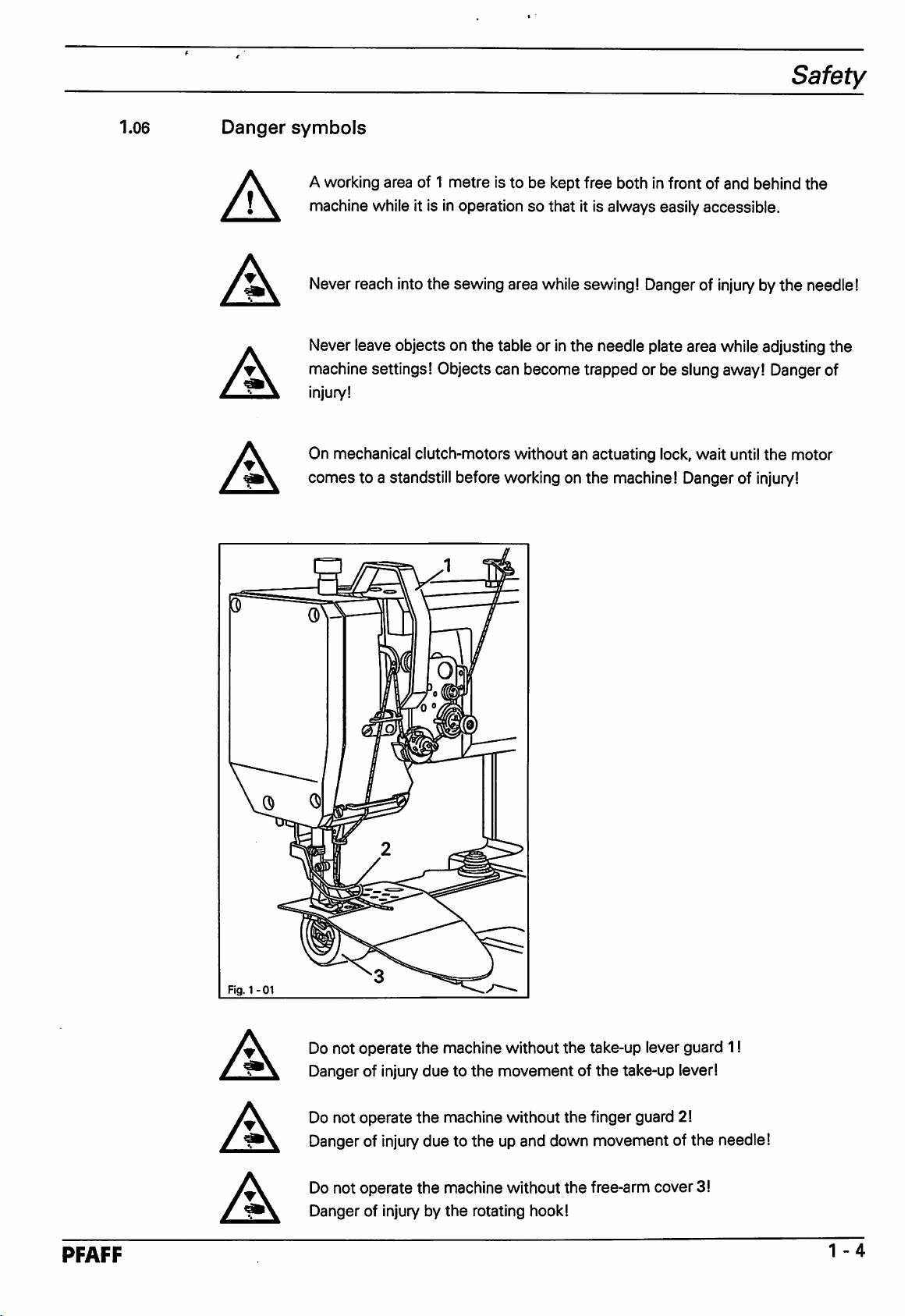
1.06
Danger
f\
A
A
•\
A
A
symbols
A working area of 1
machine
Never reach into the sewing area while sewing! Dangerof
Never leave objects on
machine settings! Objects can become trapped or be slung away! Dangerof
injury!
On mechanical clutch-motors without an actuating lock, wait until
comes
whileitisinoperationsothatitis
to a standstill before working on
metre
the
is to be kept
table or in
free
both in front of and behind
always
the
needle plate area while adjusting
the
machine! Danger of injury!
easily
accessible.
injurybythe
the
motor
the
needle!
the
Fig.
1-01
PFAFF
A
A
A
Do not
Danger of injury
Do not
Danger of injury due to
Do not operate
Danger of injury by
operate
operate
the
machine without
duetothe
the
machine without
the
the
machine without
the
rotating hook!
the
take-up lever guard 11
movementofthe
the
up and down movement of
the
take-up lever!
finger guard 2!
free-arm cover3!
the
needle!
1-4
Page 10
Safety
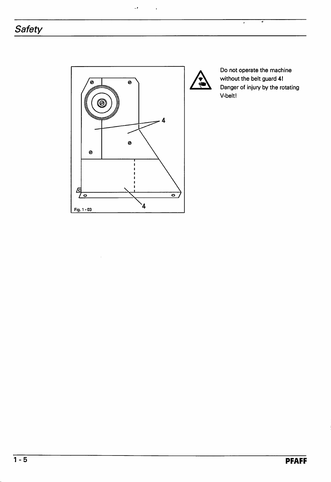
A
Do
not
operate
without
Danger of injury by
V-beltl
the
belt
the
guard
machine
4!
the
rotating
Fig. 1
-03
1-5
PFAFF
Page 11
Properuse
Proper
The
PFAFF
feeds
A
use
335 is a single needle, free-arm sewing machine with bottom, top and needle
for
sewing
lockstitch
Anyand all
manufacturer
held liable for any
The appropriate
adjustment, maintenance and repair
seams.
uses
of this machine which have not been approved of by
are
consideredtobe
damaged
useofthe
causedbythe
machine includes
inappropriate!
inappropriate
the
measures
The
manufacturer
useofthe
observance of all operational,
required by
the
manufacturer!
the
cannot
machine!
be
PFAFF
2
-1
Page 12
Specifications
3
3.01
Specifications
PFAFF
Stitch
Model: 3
Needle
Needle thickness
Max.
on
on
on
Handwheel
Max.
Dimensions
Free-arm
Free-arm
Length: approx. 770 mm
Width:
Fleight: approx. 630 mm
335
type:
301
{lockstitch)
system: 134-35
(Nm)
in 1/1GOmm: 80
stitch
length:
sub
classes
sub
class -40/63 (model N 2.5) 2.5 mm
sub
classes
-2/77; -6/01; -17/01; -39/21; -40/64; -155/01 4.5 mm
-2/77; -6/01; -17/01; -39/21; -40/64; -155/01 (model
effective
dia.:
N)
6.0 mm
speed: 2800 spm
of
the
machine:
head
dia.: 51
size:
approx.
approx.
165
380
80
-100
mm
mm
mm
mm
3.02
Widthoffabric
Height of fabric clearance: 115
Clearance
Net
weight
Working air
Air consumption:
Working
Emission
n =
1800
noise
measurement
Possible
Model
Additional
Subclass
B: For
under
clearance:
the
sewing
foot: 7
265
(sewing head): approx. 40 kg
pressure:
-0.81/work
noise
level:
at
workplaceatsewing
spm:
in
accordance
models
equipment:
-900/52
and
speed
with
subclasses
of
DIN45635-48-A-1
processing
L s 81 dB
medium
Thread
materials
trimmer
mm
mm
mm
6 bar
cycle
(A)
3
-1
PFAFF
Page 13
Disposal
of
the
machine
Disposal
• The proper disposal of machine
•
The
The electrical
•
The
environmental protection regulations. If
A
of
machine
materials
machine
usedonthe
equipment
waste
Special
disposed of in accordance with
waste
machines
consists
is tobedisposed
care
is tobetaken
wasteisthe
are
of plastics and copper.
of in
that
responsibility of
steel,
aluminium,
accordance
necessary
parts soiled with lubricants are separately
the
locally valid pollution control regulations!
the
customer.
brass
and
various plastics.
with
the
locally valid
a specialist is tobecommissioned.
PFAFF
4-1
Page 14
Transport,
packaging
and
storage
5
5.01
Transport,
packaging
Transporttothe
Within
Machines without table
packaged.
Germany,
completemachines
5.02 Transport within
The manufacturer carries no
Care is to be taken to transport
5.03
Disposalofthe
The packaging of the machine consists of wood, paper, cardboard and
The proper disposal of the packaging is the responsibility of the customer.
and
customer's
and
motor (machine
the
customer's
liability
packaging
storage
premises
(with
tableand
heads
motor)
only)
premises
for transport within
the
machine in an upright position.
the
aredelivered without
and
machines for export
customer's
premises.
VCE
packaging.
are
fibre.
5.04
Storage
The machine can be
protected
For longer storage the
be
protected
from
dust
against corrosion e.g. by a film of oil.
stored
and
moisture.
individual
for up to 6 months if not in use. During this time it should be
parts of the machine, especially the moving parts, should
5-1
PFAFF
Page 15
Explanation
of
the
symbols
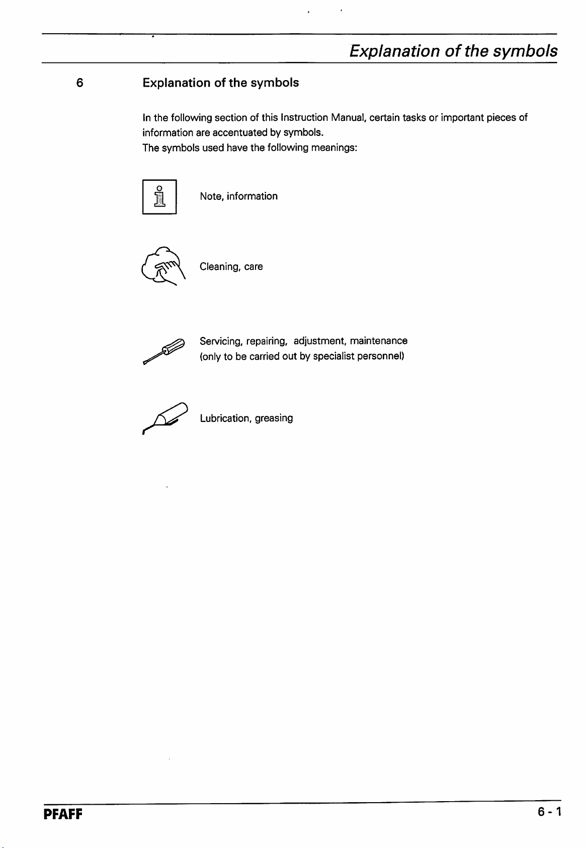
Explanation
In
the
following
information
The symbols used have
n
of
the
section
are
accentuatedbysymbols.
Note,
information
Cleaning,
Servicing, repairing, adjustment, maintenance
(onlyto be carried
symbols
of this Instruction Manual, certain
the
following meanings:
care
out
by specialist personnel)
tasksorimportant
pieces
of
Lubrication, greasing
PFAFF
6-1
Page 16
Elements
of
operation
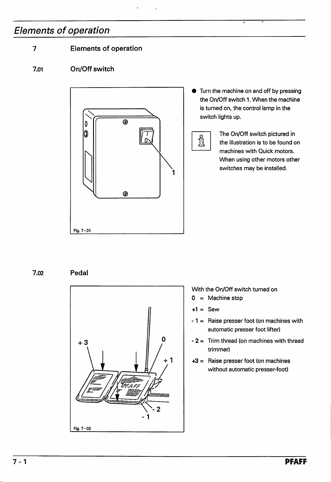
7.01
Elements
On/Off
switch
of
operation
• Turn
the
is
turned
switch
the
machineonand
On/Off
switch1.When
on,
lights up.
The
On/Off
the
illustrationistobefound
machines
When
switches
the
control lamp in
switch
with
Quick
using
other
maybeinstalled.
off by
the
pictured
motors
pressing
machine
the
in
on
motors.
other
7.02
Fig.
Pedal
7-01
With
the
On/Off
0 =
Machine
-1-1=Sew
-1
= Raise
automatic
- 2 =
Trim
trimmer)
-tS = Raise
without
stop
presser
thread
presser
automatic
switch
foot
presser
(on
foot
turned
(on
machines
foot
lifter)
machines
(on
machines
presser-foot)
on
with
with
thread
Fig.
7-02
7-1
PFAFF
Page 17
Elements
of
operation
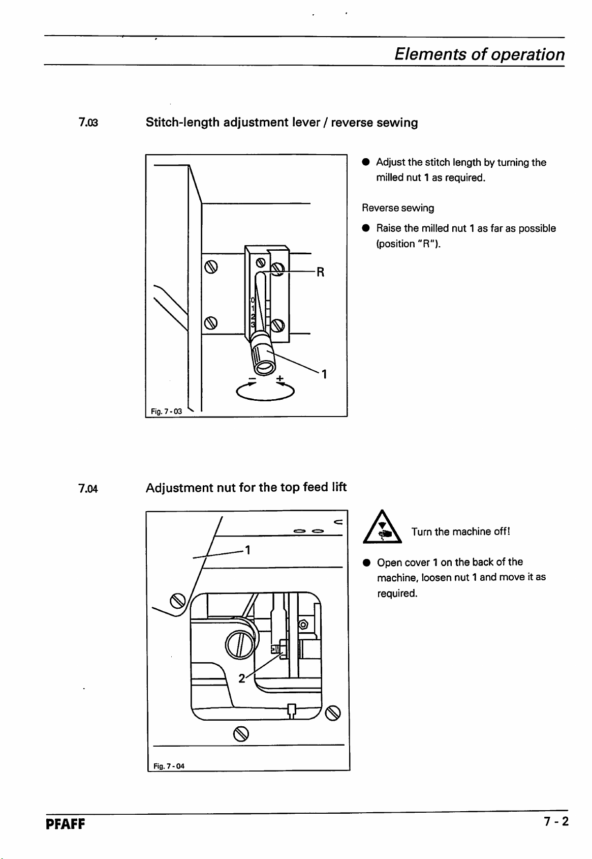
7.03
Stitch-length
Fig.
7-03
adjustment
lever /
reverse
• Adjust
Reverse
• Raise
sewing
the
stitch
length by turning
milled nut 1asrequired.
sewing
the
milled
nut1as
(position
"R").
the
faraspossible
7.04
Adjustment
Fig.
7-04
nut
m
for
the
top
feed
lift
A
Turn
Open cover 1 on
machine,
required.
the
loosen
machine
the
back of
nut1and
off!
the
moveitas
PFAFF
7-2
Page 18

Mounting
and
initial
operation
8
8.01
Mounting
I\
A
Mounting
and
initial
This machine may only be mounted and put into operation by qualified
specialists!
Connections
machine's
A solid, horizontal
Due to packaging reasons,
The
adjustmentofthe
operation
All
relevant safety regulations are to be adhered to!
for
electrical
location
{see
surface
and
compressed
chapter
table-top height is
3: Specifications).
and
adequate
the
table top is lowered for transport.
air
supplies
lighting
describedinthe
must
mustbeavailableatthe
alsobeguaranteed.
following.
8.01.01 Adjusting
Fig.
8-01
the
table
height
i
•
Loosen
Tighten
8-1
screws
screws
1 and
set
1 firmly.
the table height as desired.
PFAFF
Page 19

Mounting
and
initial
operation
8.01.02 Tightening
Fig.
8-02
the
V-belt
Loosen
Tighten
switch
Tighten
nuts
the
V-belt using
2.
nuts
1.
the
dolly
1.
Fig.
8-02 shows a Quick motor. Ifanother motor is used proceed as described
in
the
instruction
manual!
PFAFF
8-2
Page 20

Mounting
and
Initial
operation
8.01.03
Mounting
Fig.
8-03
the
upper V-belt guard
• Attach
V-beltguard 1 and 2 using
• Then
the
table
the
two
upper
screw
the
two
lower V-belt guard 3 and 4
top
with
screws
segmentsofthe
screws
lower
segments
onto
6.
5.
of
the
8.01.04 Mounting
Fig.
8-04
the
lower V-belt guard
• Align
that
run freely.
•
Tighten
the
V-belt guard 7 in
both
the
motor pulley
screws
suchaway
and
the
V-belt
8.
8-3
Fig.8-04
in
the
shows
instruction
a Quick motor. Ifanother motor is used proceedasdescribed
manual!
PFAFF
Page 21

Mounting
and
Initial
operation
8.01.05 Mounting
Screw
a
specialist.
8.01.06 Mounting
•
Mount
• Insert
8.02 initial
• Before operating the machine, check the electrical and pneumatic connections for
• Clean the machine thoroughly and then oilit (see chapter 11 Care and maintenance).
•
the
operation
possible
Have
specialist personnel checkifthe machine's motorcan be put intooperation with
the power
the
machine
the
sewing
the
sewing
the
spool holder
the
spool holder.
spool holder into
damage.
supply
available
unless
lamp
these
lamp^
onto
the
and ifthe
checks
the
hole in
table
have
top
{wood
the
table
terminal
been
screws
top
5x35)
and affix it with
boxisconnected
successfully carried
and
have it
the
properly.
out.
connected
enclosed
nuts.
Never operate
by
• The handwheel must rotate towards the operator when the machine is running.Ifthis is
not
the
case, have
• Connect the machine to
pressureofapprox.6bar.Ifnecessary,
the
air
pressure).
8.03 Switching
•
Switch
• Carry
Thesewing lampis not included inthe standard
the
outatest
the
machine altered by specialist personnel.
the
machine on/off
machineon(see
run.
the
compressed air system. The manometer must display a
chapter
adjusttothis
7.01).
value
(see
chapter
11.06
delivery.
Adjusting
PFAFF
Page 22

Preparation
Preparation
A
A
All
regulations and instructions inthis Instruction
manual
are to be observed.
Specialattention should be paidto the safety regulations!
Preparationwork is onlyto be carried out by appropriatelytrained personnel.
The machine must always be separated from the power supplybyswitchingoff
the
on/off switch or by removing
carrying
out
preparation work!
the
mains plug from
the
powersupply
when
9.01
Needle
and
thread
The choice of the correct needle depends on the machine model and the thread and material
used.
Needle
Model
B
or
Use
For
comparable
sewing
medium
thicknessesorthread
materials
types
Max.
thread
thickness
Synthetic
40/3
thickness
in
*•
1/100
80-100
(Nm)
mm
9-1
PFAFF
Page 23

Preparation
9.02
Inserting
Fig.
9-01
the
needle
A
Switch
• Loosen
• Insert
• Retighten
the
long
grooveinthe
pointingtothe
off
the
machine!
the
needle
needleasfaraspossible (The
the
needle
left).
needle
retaining
retaining
screw
must
be
screw
1.
1.
9.03
Winding
Fig.
9-02
the
bobbin
thread,
adjusting
the
thread
tension
• Place an empty bobbin onto
•
Press
the
bobbin-winder
•
The
bobbin is filled during
the
bobbin holder 1.
ratchetinthe
the
sewing
direction of
process.
the
arrow.
• The bobbinwinder stops automaticallywhen the bobbin is
• The tension of
the
thread on
the
bobbin can be adjusted with milled nut 2.
PFAFF
full.
9-2
Page 24

Preparation
9.04
Removing
Fig. 9 - 03
the
bobbin case, threading
the
bobbin
A
Removing
• Lift
Threading
•
•
of
the
case
Thread
Fig. 9-04.
The
bobbin
the
arrow
case
Switch
the
retainer1and
2.
the
the
the
bobbin
bobbin
bobbininaccordance
must
when
the
machine
case.
remove
case.
rotateinthe
thread
off!
the
bobbin
with
direction
is pulled.
9.05
Inserting
Fig.
9-04
the
bobbin
case,
adjusting
the
bobbin
A
Inserting
•
Insert
into
Adjusting
• Adjust
screw
Switch
the
the
place.
the
the
3.
thread
the
bobbin
bobbin
bobbin
bobbin
tension
machine
case.
case2so
thread
thread
off
I
thatitclicks
tension.
tension with
9-3
PFAFF
Page 25

Preparation
9.06
9.07
Fig.
9-05
Threading
the
Switch
needle
the
machine
thread
off!
A
• Thread
is
Adjusting
Adjusttension 1 so that the stitch loops are insidethe sewing material.
the
threaded
machine in accordance with Fig. 9-05, taking care to ensure
from
the
left
(see
arrow).
the
needle
thread
tension
that
the
needle
PFAFF
9-4
Page 26

Care
and
10
maintenance
Care
and
maintenance
10.01
Servicing
Cleaning
General lubrication
intervals
daily,
moreoftenifin
continuous operation
twice
weekly
Lubricating the sewing head twice weekly
Lubricating the hook daily
Checking the air pressure dailybefore starting sewing
Water
containerofthe
service
unit daily
before
starting
sewing
10.02
Cleaning
Fig.
10-01
• To
reassemble
caretoensure
the
slot
• Unscrew
•
The
replace
6.
the
hook finger 3
the
the
that
free
bobbin
the
projection on
arm
cover.
compartment,
the
and
insert
the
A
• Clean
daily,
operation.
• Raise
position
•
Remove
•
Unscrew
position-finger1.
•
Unscrew
finger 3.
• Turn
same
•
Remove
hook
carry
out
backofthe
bobbin with
Switch
the
more
the
and
the
the
screw2and
the
handwheel
heightasthe
the
race
these
steps
bobbin
the
the
machine
hook
and
hook
often
whenincontinuous
needle
bartoits
remove
bobbin
bobbin
the
and
case
until
free-arm
the
remove
hook point 5.
bobbin
with
case
petroleum.
in reverse order. Take
case
position-finger 1 is in
bobbin
case.
off!
compartment
highest
cover.
bobbin
point
and
case.
the
hook
4 isatthe
clean
the
10-1
PFAFF
Page 27

Care
and
maintenance
10.03
General
lubrication
\
©
I
Fig.
A
10-02
^
Only
use
oil
with a mean viscosity of 22.0 mmVsat 40°Cand a density of 0.865
g/cm^at15°C!
We
recommend
PFAFF
sewing
machine
oil.
Part
no.
280-1
-120
144.
A
• Oilallof
in Fig. 10-02 and 10-03 twice a week.
• To reach
Fig.10-03,
and lay
• Using both hands stand the sewing head
up so that it
• Lift
and place the sewing head in an upright
position.
Switch
the
the
sewing head slightly, pull piston 1
off
the
machine!
the
bearings which
the
oilingpoints marked in
pull
out piston 1
sewing head on its back.
rests
on piston 1.
are
(Fig.
marked
10-02)
Danger of crushing
sewing head and pedestal!
PFAFF
Fig.
A
10-03
between
10-2
Page 28

Care
and
maintenance
10.04
Lubricating
/°
mfW
Jl
Fig.
10-W
the
sewing
J
i
fflflk
^1''
jRCUJlCT
.H
head
w/
1
LW
oi
V
A
Unscrew
week
sliding
Replace
Switch
the
and
oil all of
surfaces
the
off
sewing
marked
sewing
the
the
head
machine!
head
bearings
cover
twice
and
in Fig. 10-04.
cover.
a
10.05
A
^ We
Lubricating
Only
use
oil with a
g/cm=^at15°C!
recommend
the
hook
mean
PFAFF
viscosity of 22.0 mmVsat40®C
sewing
machine
oil.
Part
Switch
no.
A
•
Remove
1to2
(Fig. 10-06) daily.
•
Re-insert
the
drops
the
bobbin
of oil into
bobbin
andadensityof0.865
280-1
-120
144.
off
the
machine!
case
and
the
hook
case.
squeeze
race
0
Fig.
10-05
10-3
Fig.
10-06
PFAFF
Page 29

Care
and
maintenance
10.06
Adjusting
Fig.
10-07
the
air
>®o
pressure
• Before using
the
air
the
pressureonthe
• The manometer
of
approx.6bar.
• If
the
reading is different, adjust the
pressuretothis
• Todoso,
manometer
lift
button2and
displays a
machine, always check
manometer
must
display a pressure
value.
turn
pressure
1.
it until
of 6
the
bar.
10.07
Emptying/Cleaning
Fig.
10-08
the
max.
water
container
A
Emptying
•
Cleaning
•
• Clean
•
of
the
air
filter
Turn
the
machine
Water
when
the
removed
the
Unscrew
the
Remove
from
the
trap 1
from
water
the
compressed-air
the
air
filter.
water
trap
1
empties
compressed-air
the
filter 2
filter
itself automatically
air
filter.
trap1and
with
compressed
with isopropyl alcohol. Part
95-665735-91.
Screw
back
filter2backinand
on.
off
I
hose
filter 2.
number
water
is
trap
hose
air or
1
PFAFF
10-4
Page 30

Adjustment
n
11.01
11.02
Adjustment
Tools,
•
• Spanners (wrenches) with jaw width from 7 to 14 mm
• Allan keys from 2 to 6
•
• Adjustment gauge, Part No. 08-880 218-00
•
• Gauge, (top
•
•
Notes
gauges
Screwdrivers
Metal
rule,
Terminal
Needles,
Sewing
screw.
system
thread
on
adjusting
and
with
other
blade
accessories
width
from2to10mm
mm
Part
No.
08-880
Part
feed
lift 7 mm). Part No. 61-111 630-14
No.
218-00
08-880
137-00
134-35
and
test
material
11.03
All
adjustmentsinthis
the
machine
not
mentioned
before
Abbreviations
tdc=top
bdc=bottom
which
making
dead
in
the
the
adjustment
center
dead
manual
havetobe
text.
The
center
are
based
removed
screws
and
tightened
and
on a
and
nuts
completely
replaced
written
again
when
assembled
for
checks
in
brackets
the
and
adjustment
aretobe
machine.
Covers
work
loosened
adjustmentiscomplete.
on
are
11-1
PFAFF
Page 31

Adjustment
11.04
11.04.01
11.04.01.01
Adjusting
Positioning
the
the
basic
feed
Lateral positioning of
Requirement
The clearances from
must
be
the the
the
same
machine
dog
the
left
and
size.
feed
dog
right of
the
bottom
feed
dog 1 to
the
needle
plate
cutout
•
a
Fig.
11-01
Movethe bottomfeed dog 1 (screws 2) inaccordance with the requirement.
PFAFF
11
-2
Page 32

Adjustment
11.04.01.02
Lengthwise positioning of
Requirement
With the stitch length
set
the
feed
dog
at its longest the clearances behind and infront of the bottom
feed dog 5 to the needle plate cutout must be the same.
Fig.
11-02
•
Set
the
11-3
•
Move
of
the
•
Loosen
•
Move
• Tighten
longest
the
rock shaft. The left
screws
the
screws
clamp
bottom
stitch
length.
piece1(screws2)as
4.
4.
feed
screw
dog
5 in
accordance
must
fartothe
stillbeon
with
leftaspossibleonthe
the
clamp surface.
the
requirement.
clamp
surface
PFAFF
3
Page 33

Adjustment
11.04.02
Centering
Requirement
With
the
middle.
the
needle
stitch length
set
in
the
at "0"
needle
the
needle
hole
must
enter
the
needle hole exactly in
the
i
PFAFF
Fig.
11-03
• Unscrew
•
Set
the
•
Insertanew
•
Bring
the needle to a
handwheel.
•
Move
the
• Tighten
•
Position
So
the
vibrating
stitch length at "0" and bringthe needle to its tdc.
needle.
needle
screws
stop 8 so that it istouching the needle barframe 7 and tighten screw 6.
Theneedle barframe7 inguide9 andthe
move
bar
3, 4
freely.
presser
Loosen
position
frame
and
5.
foot 1 and
screws3,4, 5
directly
7 in
overthe bottom feed dog by turning the
accordance
the
presser foot 2.
and
6.
with
the
requirement.
vibrating
presser
drive
shaft must
11
-4
Page 34

Adjustment
11.04.03
Pre-adjusting
Requirement
With
the
needle
must
be
15
mm.
the
needle
baratits
bdc
height
the
distance
between
the
needle
bar
and
the
needle
plate
Fig. 11
-04
Move
the
needle
11-5
bar1(screw
2) in
accordance
with
the
requirement
without
twisting it.
PFAFF
Page 35

Adjustment
11.04.04
Driving
Requirement
With
the
dogs
should
motion
longest stitch length
not
of
move
the
when
top
the
and
set
bottom
and
the
reverse
feed
dogs
needle bar at its bdc
feed
lever is activated.
the
top
and
bottom
feed
Fig. 11
-05
•
Set
the
PFAFF
longest
• Loosen screw 1 far enough so that the feed
shaft
with
• Bring
•
• Tighten
While
it
slightly
the
keeping
screws
stitch
length.
some
difficulty.
needle to its bdc.
this
position,
movethe feed
so that the requirement is
1.
fulfilled
driving
driving
eccentric 2 can be turned on the
eccentric2 to the top and then move
whenthe reversefeed
leverisactivated.
11
-6
Page 36

Adjustment
11.04.05
Needle
Requirement
Withthe stitch length
must
be
rise,
hook-to-needle
correct:
clearance
set
at "0" (1.8 mm after the bdc of the needle bar)the following
and
needle
height
1. The hook point must be opposite the middleof the needle and the distance to the
needle
must
be
0.05-0.1
mm.
2. The top edge of the needle eye must be 0.8 mm from the hook point.
Fig.
11-06
Set
the
11
-7
stitch lengthat"0"
machine).
Bring
the
needletoits
under
the
needle bar bearing. Position
plate
and
screw
Remove
screw
Move
Rotate
Bring
the
clampistouching
the
hook on
the
the
hook
Taking care to
On machines with a thread trimmer
a
shaft
it tight.
measuring
the
hook in accordance with requirement 2 (adjust needle height if necessary).
shaft
ensure
and
the
adjustmentofthe
and
bdc
and
plate
and
the
needle
hook
shaftinaccordance
bearing 3 to
that
the
bevel
loosen
slide
the
turn
bar
restonthe
gear
screws
1.8
mm
the
screw
the
handwheel
bearing.
hook
4 is resting on
the
adjustment of
hook
shaft
1 and 2
(screw
measuring
plate
clampsothat it
in its direction of rotation until
with
requirement
and
tighten
the
bearing, tighten
the
bearing3are
2 is on
the
with
restsonthe
1.
screw
2.
axial play on
not
necessary.
its
back of
slot
directly
measuring
screws
the
the
the
1.
hook
PFAFF
Page 37

Adjustment
11.04.06
Vibrating
Requirement
With
the
point
must
at
maximum.
presser
presser
both reach
feeding
foot 3 resting on
the
needle
motion
the
needle
plate at
the
plate
same
the
time
vibrating
with
presser6and
the
vibrating
the
presser
needle
stroke
0
Fig.
11-07
•
Loosen
• Slide bolt 2 upwards in
• Allow
the
nut
presser
1.
foot 3 to rest on
the
elongated hole and tighten nut 1.
the
needle plate.
• Loosen screws 4 enough so that the feed
difficulty.
• Rotate the
• Tighten
• Carry
lifting
screws
outacheck.
4.
eccentric 5 in accordance with the requirement.
lifting
eccentric 5 can be rotated with
PFAFF
11
-8
Page 38

Adjustment
11.04.07
Vibrating
Requirement
With
the
and
vibrating
is
rotated.
presser
vibrating
lift
presser
presserfoot2 must
liftatmaximum
lift
7.0 mm
andthe stitch lengthset at "0", presser foot 1
from
the needle platewhenthe handwheel
m
7
mm
Fig.
11-08
Set
the
11
-9
vibrating
Allow
the
the
Turn
reached
Turn
crank3(screws
Carry
outacheck.
presser
handwheel
its
highest
presser
foot
lift at maximum
1 to
restonthe
in its direction of rotation until
point.
4) in
accordance
and
needle
with
the
stitch lengthat"0".
plate.
the
vibrating
the
requirement.
presser
foot 2
has
PFAFF
Page 39

Adjustment
11.04.08
Needle
Requirement
With
thread
the
tension
presser
foot lifted,
The distance of 0.5
to
more
than1mm
release
the
two
mmisthe
with
tension disks
minimum clearance. The clearance
thick
threads.
must
be at least 0.5
]
mm
apart.
can
range up
Fig. 11
-09
• Raise
•
Align
requirement.
0.5
mm
<-/
V-/
the
presser
foot
using
the
hand
lever.
the compression plate 1 behind the tension bearingboard 2 inaccordance with the
o
When
the
a
tension
is correct
the
release
pin
must
PFAFF
notbeunder
pressure.
11-10
Page 40

Adjustment
11.04.09
Thread
Requirement
check
spring
The movement of the thread check spring must be finished
the material (= approx. 7 mm spring movement).
The length of the spring movement can varya
changesinthe
sewing
parameters.
vy/hen
the needle point enters
little
upwards or downwards due to
o
7
mm
Fig.
11-10
Thread
foot
Loosen
Sew a few stitches by turning the handwheel and then raise the take-up lever to its tdc.
When continuing to turn the handwheel
spring 2
Inthis position bring stop 3 to rest on
onto
the
machine, place
the
material using
screw
should
1.
move
the
the
back
about7mm.
test
material under
hand
lever.
the
the
presser
(in
direction of rotation)
thread check spring and tighten
foot and lower
the
thread check
the
screw
presser
1.
11-11
PFAFF
Page 41

Adjustment
11.04.10
Bobbin
Requirement
1. With
2.
bobbin
wheel
The
bobbin
the
reached
winder
bobbin
winder
1.
winder
disengaged, however,
winder
a point approx. 1
must
engaged
stop
automatically
mm
the
below
winder
the
friction
the
bobbin rim.
spindle
wheel5must
when
the
mustbedriven reliably. With
not
touch
the
drive
thread
woundonthe
bobbin
the
has
1
mm
Fig.
11-11
Adjust
Placea
winder.
the
drive
bobbin
wheel 1 (screws2)inaccordance with requirement 1.
on the winder spindle,thread the bobbinand switch on the bobbin
Shiftthe regulating pin3 (screws4)inaccordancewith requirement 2.
PFAFF
11
-12
Page 42

Adjustment
11.04.11
Regulating the pressure on the presser foot
Requirement
The material must be fed perfectlyeven at top sewing speed. There must not be any
pressure marks on the material.
Fig.
11-12
Turn
screw
11-13
1 in
accordance
with
the
requirement.
PFAFF
Page 43

Adjustment
11.05
11.05.01
Adjusting
Preadjusting
Requirement
With
the
take-up
underneath
the
the
thread
the
lever
cam
control
at its
follower
trimmer
cam
bdc,
projection
5.
-900/52 (optional)
4onthe
control
cam2 must be
@1
^iTr
directly
Fig.
11-13
•
Loosen
• Bring
• Turn
• In this position,
bearing 3
•
Make
• Carry
the
two
screwsonthe
the
take-up lever to its
the
control
the
outacheck.
cam
and
below
second
2 on its
taking
it,
tighten
screwonthe
control
bdc
shaftinaccordance
caretoensure
the
accessible
cam2through
by turning
control
that
screwonthe
cam2accessible
the
handwheel.
with
the
the
the
control
assembly
requirement.
cam
control
and
PFAFF
hole
2 is touching
cam
2.
tighten
it.
1.
the
11-14
Page 44

Adjustment
11.05.02
Tripping lever height
Requirement
With the needle bar at its bdc there must be a distance of 1.0 mm between the tripping
lever3and
the
control
cam
4.
ozn.
3
I
mm
Fig.
11-14
Bring
the
needle bar to its bdc by turning
Move the carrier 1 (screws 2)of the tripping lever 3 in the elongated hole in accordance
with
the
requirement.
the
handwheel.
11-15
PFAFF
Page 45

Adjustment
11.05.03
Feed
regulator pin
Requirement
Withthe needle barat its bdc, the feed regulatorpin 6 must be able to
path of
the
control
cam7when
the
engaging solenoid 6 is activated.
«
fall
lightly
intothe
I
Fig.
11-15
• Bring
• Activate
• Tighten lockingscrew 2 (nut 3) far enough so that it just touches
• Loosen
• Carry
is in
the
needle
the
magnet
locking
accordance
outacheck.
bar to its
screw 2 approx. 1/2 a turn
with
bdc
core
1 manually.
the
requirement.
by turning
the
handwheel.
until
the movement of the feed regulator pin 5
o
the
tripping lever 4.
PFAFF
11
-16
Page 46

Adjustment
11.05.04
Engaging solenoid
Requirement
With
the
needle
clearance of approx. 0.5
bar at its bdc and with
the
magnet
mm
between the pawl 7 and the retainingcollar6.
core 1 fully activated,
there
must
be a
11-17
Fig.
n-16
Bring
Push
Loosen
Move
In
this
Carry
the
needle
the
magnet
screws
the
magnet
position,
outacheck.
If
the
magnet housing 4 touches lever 4, move lever 4 (screw 5) a little to
left.
bar
to its
bdc
core
1 inasfarasit will go
2.
housing 3 axially in
tighten
screws
by turning
accordance
2.
the
handwheel.
and
leave it in this position.
with
the
requirement.
\
the
PFAFF
Page 47

Adjustment
11.05.05 Adjusting
Requirement
With
the
a
clearanceof0.3
regulator pin.
the
heightofthe
thread
trimmer
mm
feed
in resting position
between
the
highest
regulator pin
and
the
point of
pawl 4 clicked in place
the
control
cam5and
there
the
must
feed
be
PFAFF
Fig.
11-17
Bring
Activate
Allow
Carry
O
the needle bar to its tdc byturningthe handwheel.
the
magnet
the
retaining
With
the
requirement
outacheck.
0.3
mm
core
1.
collar2(screws
pawl4clicked
(see
large circle).
into
3)to
place,
lightly
touch
pawl
thisadjustmentprocedure
4 (see
arrowinsmall
fulfills
the
circle).
11
-18
Page 48

Adjustment
11.05.06
Thread catcher, front point of reversal
Requirement
With the thread catcher 3 at its front point of reversal, the rear edge of the thread catcher
cutout
must
still be 1
mm
over
the
front
edgeofthe
bobbin
case
position-finger 6.
11-19
1
mm
Fig.
11-18
Bring
the
needle bar to its bdc by turning
the
handwheel.
Activatethe magnet core 1 allowingthe feed regulator pin 2 to
cam.
Bring
the
thread catcher 3 to its front point of reversal by turning the handwheel in its
direction
Loosen
Adjust
catcher
Tighten
of
rotation.
screws
the
carrier
screws
4.
thread catcher 3 in accordance with
5.
4.
the
requirement by turning
J
'ysLjJr
fall
into the path of the
the
thread
PFAFF
Page 49

Adjustment
11.05.07
Lateral
Requirement
With
middleofthe
adjustmentofthe
the
needle
needle.
baratits bdc,
thread
the
tip of
catcher
the
thread
S 9
catcher3must
point exactlyatthe
Fig.
11-19
Remove
Bring
Align
Activate
tdc.
thread bobbin case position-finger 6 duringits course of movement.
Screw
PFAFF
knife 1
the needle barto its bdcby
the
thread
the
Take
care to ensure that the thread catcher 3 does notcome intocontact with the
on
(screws
2).
turning
the handwheel.
catcher3(screws4)laterallyinaccordance
magnet
knife1(screws
core
manually
2).
and
turn
the
handwheel
with
until
the
requirement.
the
needle
barisatits
11-20
Page 50

Adjustment
11.05.08 Control
Requirement
Withthe end of the thread guard 2 mm behindthe
finger
be approx. 4 mm as viewed inthe direction of feed.
cam,
final
adjustment
3,the clearance between the threadcatcher
^3
middle
point
ofthe
4andthe thread
bobbin
case position-
guard
2 must
11-21
2
mm
Fig.
11-20
Bring
the
Activate
needle bar to its bdc by turning
the
magnet1core
manually.
the
handwheel.
Continueturningthe handwheel (direction of rotation)
4
mm
until
the end of the thread guard 2
is 2 mm behind the middleof the bobbin case position-finger3 as viewed in the direction
of
feed.
Inthis position
requirement.
Ifnecessary, adjust
the
positionof the thread catcher point 4 must be in accordance with the
the
control
cam
accordingly
(see
page 11-14).
PFAFF
Page 51

Adjustment
11.05.09
Knife
Requirement
With
the
edge
knife
left
edgeofthe
must
thread catcher notch 1
be flush with
the
edgeofthe
mm
infront of
thread catcher (see arrow in circle).
the
knife edge,
the
left
Fig.
11-21
•
PFAFF
Loosen
•
Bring
•
Turn
the
•
Laterally
• Tighten
•
By
the
screws2on
the
needle
knife
bartoits
1.
bdcbyturning
the handwheelinits direction of rotation
same
align
screws
turning
knife
levelasthe
knife1in
the
handwheel,
blade.
knife
2.
Re-adjust
blade.
accordance
check
the
thread
with
that
the
catcher 4ifnecessary (see page
the
handwheel
until
and
the pointof the thread catcher 4 is at
the requirement (see
backofthe
thread
activate
arrow).
catcher
the
magnet
does
11-20).
not
core
catch
11
3.
on
-22
Page 52

Adjustment
11.05.10
Triggering
Requirement
the
needle
thread
tension
With the tip of the release lever 5 at the highest point of
tension
disks
mustbeat
0 ~n O
least5mm
apart.
the
tension release cam 4,
the
Fig.
11-22
11
• Bring
• Bring
•
• Adjust
• Finish
-23
the
the
Turn
the
handwheel
front
pointofreversal.
the
sewing
needle
foot to
bartoits
in
heightofthe
restonthe
bdc
by turning
its
direction
transmission
tension disks is in accordance with
the
thread trimming
to its
tdc.
In this position
Finally, apply a light
release
lever
5.
coatofgreasetothe
process
the
needle
needle
of
the
rotation
plate using
handwheel
until
bar2(screws3)so
the
requirement.
by turning
thread
the
tension
surfaceofthe
the
hand lever.
and
activate
the
thread
catcher
that
handwheel
and
mustbefully activated.
release
the
distance
bring
cam4and
the
has
magnet
reached
the
between
take
up lever
the
tip of
PFAFF
core
its
1.
the
the
Page 53

Adjustment
11.05.11
Cutting
Requirement
Both
test
threads
r
mustbetrimmed
0
perfectly.
Q ©
Fig.
11-23
Bring
PFAFF
the needle bar to its bdc byturning
Turn
the
handwheelinits
point of reversal.
Takeone thread doubled and pullit into
cutting
If
the
test
by continuing to turn
one of the threads is not cut properly, adjust the relationshipof
knife
(11-20).
directionofrotation
the
the
handwheel and activate the magnet core 1.
until
the
cutout of
handwheel.
the
thread
the
thread catcher 2. Carry out a
catcher
the
2 isatits
thread catcher to
front
11-24
Page 54

Adjustment
11.05.12
Positioner
Requirement
When interrupting the sewing procedure the machinemust position itselfat 4 mm after
the bdc of the needle bar. After trimming
the
tdcofthe
Carry
take-up
lever.
out the adjustment in accordance with the instruction manualof the motor.
the
thread, the machine must position itself at
11-25
PFAFF
Page 55

Notei
PFAFF
11
-2(
Page 56

PFAFF
G.M.
PFAFF
Aktiengesellschaft
Postfach
D-67653
Konigstr.
D-67655
Telefon:(0631)
Telefax;
Telex:
Geclrijcltiinder
Pfinied in Gefmany
ImpnmeenR.F.A.
Impresoenla R.F.A.
Stampaio
OTneyaiaMo
3020
Kaiserslautern
154
Kaiserslautern
(0631)
45753
BRD
in R.F.G.
®Pr
200-0
172
PFAFF
02
D
 Loading...