

Page 1

1295
Industrial
®
1296
ADJUSTMENT MANUAL
This Adjustment Manual is valid for machines
from the following serial numbers onwards:
# 2 730 099
296-12-18 640/002
Justieranleitung engl. 06.09
Page 2

The reprinting, copying or translation of PFAFF Adjustment Manuals, whether in whole or
in part, is only permitted with our previous authorization and with written reference to the
source.
PFAFF Industriesysteme
und Maschinen AG
Hans-Geiger-Str. 12 - IG Nord
D-67661 Kaiserslautern
Page 3

Contents
Contents ............................................................................... Chapter - Page
13
13.01 Notes on adjustment ................................................................................................ 13 - 1
13.02 Tools, gauges and other equipment .......................................................................... 13 - 1
13.03 Abbreviations ............................................................................................................ 13 - 1
13.04 Explanation of the symbols ...................................................................................... 13 - 1
13.05 Adjusting the basic machine ................................................................................. 13 - 2
13.05.01 Position of the bottom feed dog crosswise to sewing direction ................................ 13 - 2
13.05.02 Adjusting the bottom feed dog in sewing direction .................................................... 13 - 3
13.05.03 Bottom feed dog height ............................................................................................ 13 - 4
13.05.04 Needle height (preliminary adjustment) ..................................................................... 13 - 5
13.05.05 Needle in needle-hole centre ..................................................................................... 13 - 6
13.05.06 Bottom feed dog lifting motion .................................................................................. 13 - 7
13.05.07 Feeding stroke of bottom and top feeds .................................................................... 13 - 8
13.05.08 Hook clearance, needle rise, needle height and needle guard ................................... 13 - 9
13.05.09 Top feed stroke ......................................................................................................... 13 - 11
13.05.10 Top feed lifting motion .............................................................................................. 13 - 12
13.05.11 Bobbin case opener .................................................................................................. 13 - 13
13.05.12 Slip coupling ............................................................................................................. 11 -14
13.05.13 Needle-thread tension release ................................................................................... 13 - 15
13.05.14 Thread check spring, without subclass -900/56 ........................................................ 13 - 16
13.05.15 Thread check spring on the PFAFF 1296 with subclass -900/56 ............................... 13 - 17
13.05.16 Bobbin winder .......................................................................................................... 13 - 18
13.05.17 Pressure of the lifting presser ................................................................................... 11 - 19
Adjustment .............................................................................................................. 13 - 1
13.06 Adjusting the thread trimmer -900/56 ........................................................................ 13 - 20
13.06.01 Engaging solenoid ..................................................................................................... 13 - 20
13.06.02 Control cam (preliminary adjustment) ....................................................................... 13 - 21
13.06.03 Control lever spring action ........................................................................................ 11 - 22
13.06.04 Control lever stroke .................................................................................................. 13 - 23
13.06.05 Thread-trimmer drive linkage .................................................................................... 13 - 24
13.06.06 Linkage bar (only on the PFAFF 1296) ....................................................................... 13 - 25
13.06.07 Thread catcher height ............................................................................................... 13 - 26
13.06.08 Thread catcher resting position ................................................................................. 13 - 27
13.06.09 Knife pressure .......................................................................................................... 13 - 28
13.06.10 Bobbin thread trapping spring ................................................................................... 13 - 29
13.06.11 Control cam (final adjustment) .................................................................................. 13 - 30
13.06.12 Release lever............................................................................................................ 11 - 31
13.06.13 Release rod .............................................................................................................. 13 - 32
13.07 Parameter settings ................................................................................................... 13 - 33
13.07.01 Parameter list ........................................................................................................... 13 - 33
14 Circuit diagrams ....................................................................................................... 14 - 01
Page 4

Adjustment
13 Adjustment
13.01 Notes on adjustment
Please observe all notes from Chapter 1 Safety of the instruction manual! In
particular care must be taken to see that all protective devices are refitted
properly after adjustment, see Chapter 1.06 Danger warnings of the instruction
manual!
Unless stated otherwise, during all adjustment work the machine must be
disconnected from the electric and pneumatic power supply!
Danger of injury if the machine is started accidentally!
For the adjustments in this chapter the PFAFF 1296 two-needle machine is
illustrated. On the PFAFF 1295 single-needle machines various adjustments only
have to be carried out on one side, i.e. in the right-hand hook area. This is
referred to in the different chapters.
All following adjustments are based on a fully assembled machine and may only be carried
out by expert staff trained for this purpose.
Machine covers, which have to be removed and replaced to carry out checks and
adjustments, are not mentioned in the text.
The order of the following chapters corresponds to the most logical work sequence for
machines which have to be completely adjusted. If only specific individual work steps are
carried out, both the preceding and following chapters must be observed.
Screws, nuts indicated in brackets ( ) are fastenings for machine parts, which must be
loosened before adjustment and tightened again afterwards.
13.02 Tools, gauges and other equipment
● Screwdrivers withi blade widths from 2 to 10 mm
● Spanners (wrenches) in sizes from 7 to 13 mm
● Allen keys from 1.5 to 6 mm
● Metal rule (part No. 08-880 218-00)
● Needle-rise gauge (part No. 61-111 600-01)
● Gauge, (top feed stroke 7 mm) (Part No. 61-111 633-61)
● Screw clamp (part No. 61-111 600-35)
13.03 Abbreviations
t.d.c. = top dead centre
b.d.c. = bottom dead centre
13.04 Explanation of the symbols
In this adjustment manual, symbols emphasize operations to be carried out or important
information. The symbols used have the following meaning:
Note, information
13 - 1
Service, repair, adjustment, maintenance
(work to be carried out by qualified staff only)
Page 5
13.05 Adjusting the basic machine
13
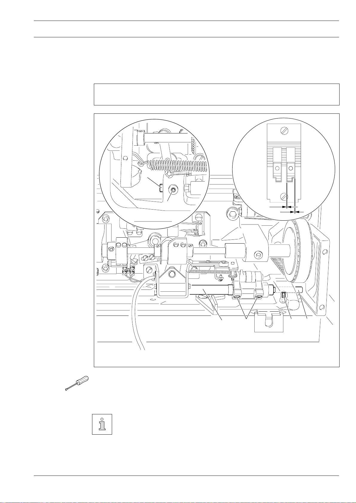
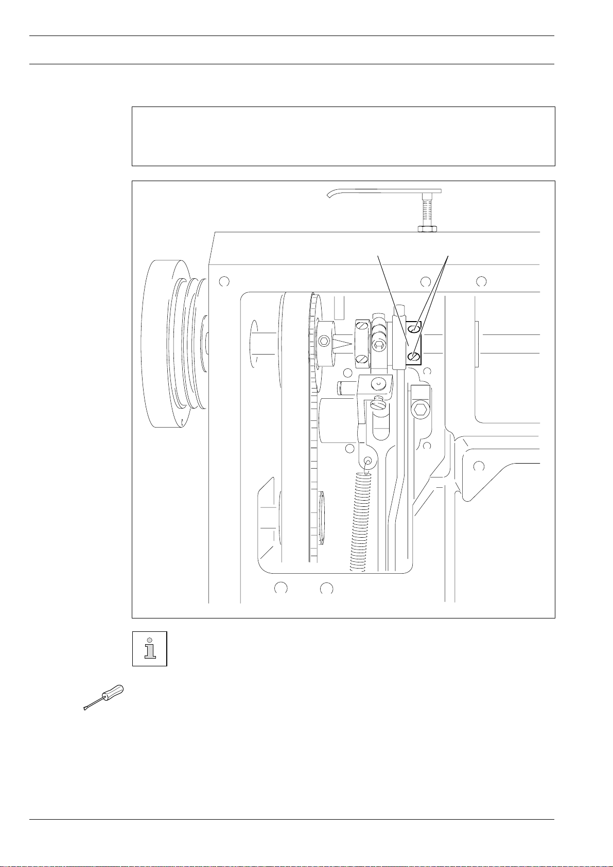
.05.01 Position of the bottom feed dog crosswise to sewing direction
Requirement
The bottom feed dog must be the same distance from the left and right side of the feed slots.
4
Adjustment
Fig. 11 - 01
1
X
X
3
2
4
1
● Loosen screws 1 and 2.
● Position rock shaft 3 according to Requirement..
● Tighten screw 1.
The flats of pins 4 must face screws 1 and rock shaft 3 must neither have any
play nor bind.
Leave screws 2 loose for the following adjustments.
13 - 2
Page 6
Adjustment
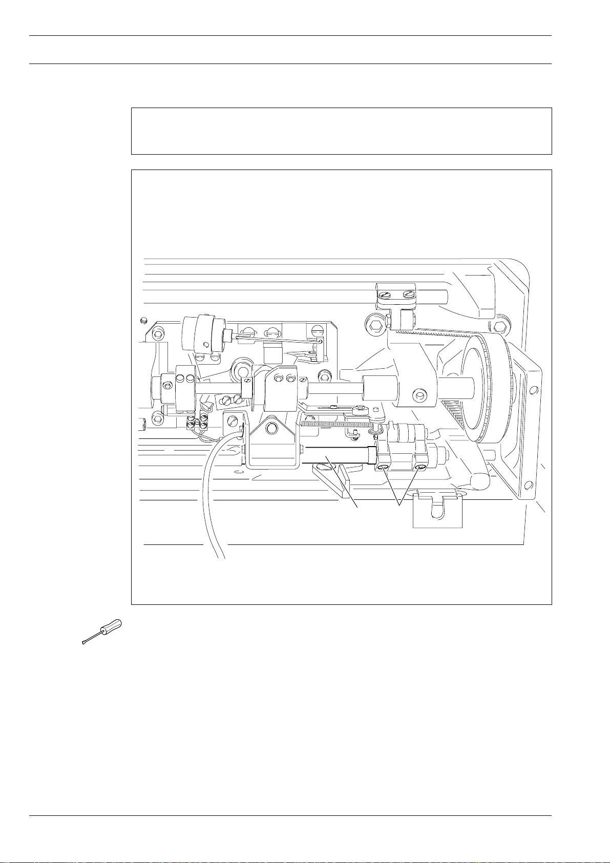
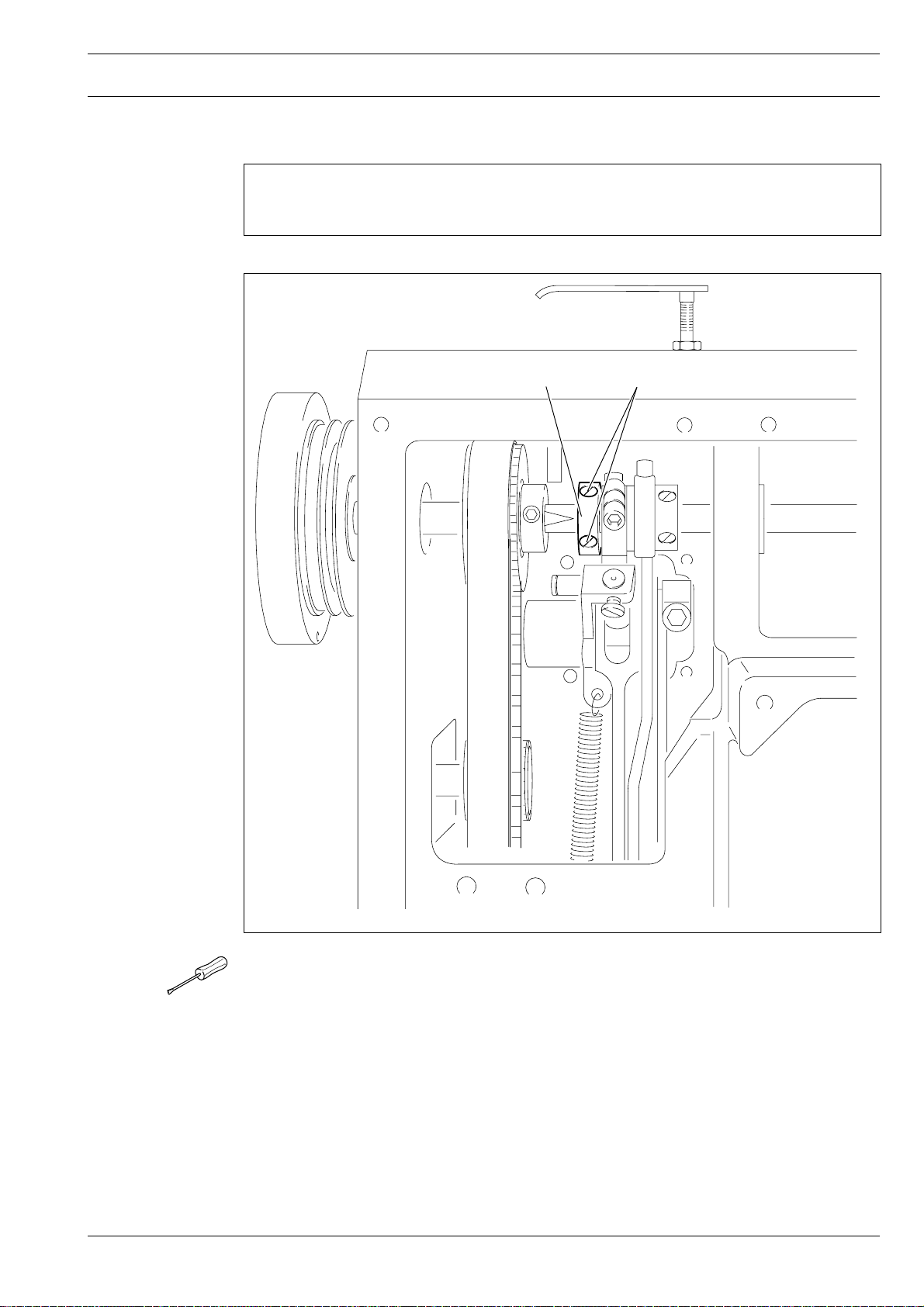
13.05.02 Adjusting the bottom feed dog in sewing direction
Requirement
With the longest stitch length set, the bottom feed dog must not strike the feed slot at the
front or rear end of its stroke.
1
Fig. 11 - 02
● Set the longest stitch length.
● Turn rock shaft 1 according to Requirement. and tighten screws 2.
2
13 - 3
Page 7
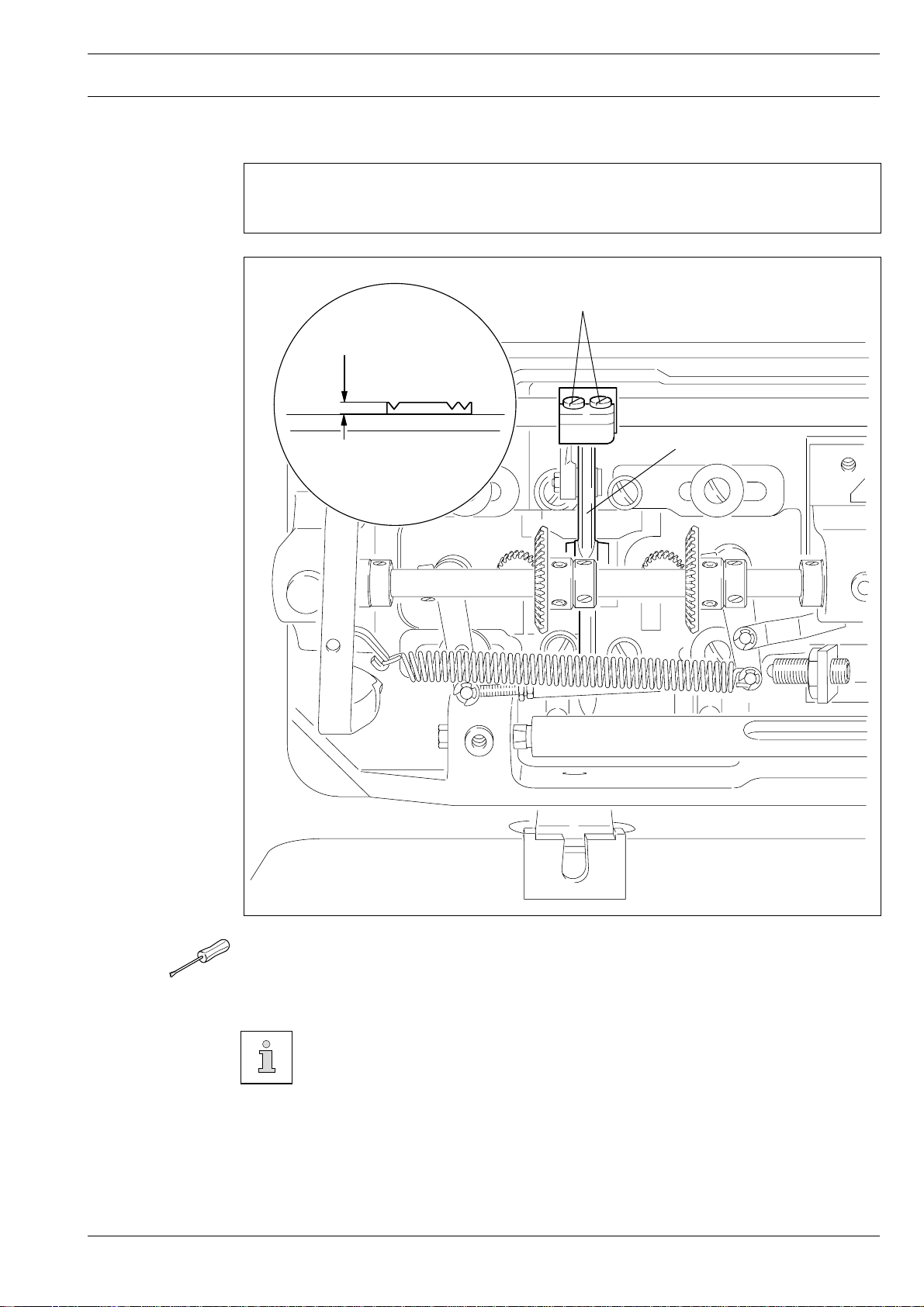
13.05.03 Bottom feed dog height
Requirement
With the stitch length set at "0" the feed dog must protrude from the needle plate by the
height of its teeth when at its highest position.
tooth height
Adjustment
2
1
Fig. 11 - 03
● Set stitch length „0“.
● Turn the balance wheel to set the bottom feed dog at its highest position.
● Adjust bracket 1 (screws 2) according to Requirement.
On machines without bottom-feed lifting phase (without "P") the feed dog
height may be reduced somewhat if necessary.
13 - 4
Page 8
Adjustment
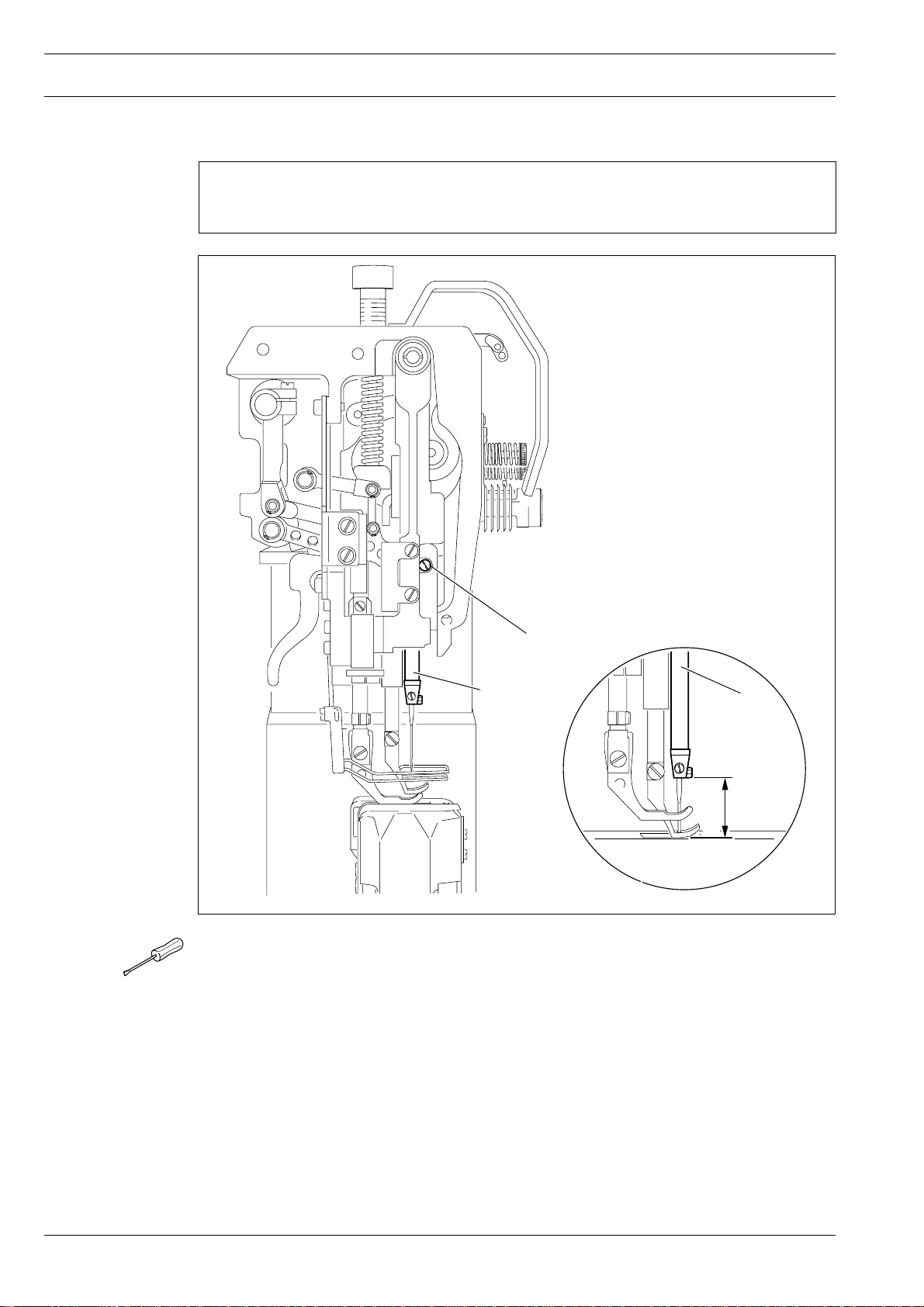
13.05.04 Needle height (preliminary adjustment)
Requirement
With the needle bar at b.d.c. the clearance between needle bar and needle plate must be
15 mm.
2
1
Fig. 11 - 04
● Re-position the height of needle bar 1 (screws 2) according to Requirement, but do not
turn it.
1
15 mm
13 - 5
Page 9

1
2
3
0
13.05.05 Needle in needle-hole centre
Requirement
With the stitch length set at "0" the needle must enter exactly in the centre of the needle
hole.
Adjustment
4
3
7
5
6
8
9
1
2
Fig. 11 - 05
● Remove vibrating presser 1 and lifting presser 2.
● Set the stitch length at "0" and set the needle bar at t.d.c.
● Insert a new needle, loosen screws 3, 4, 5 and 6.
● Turn the balance wheel to set the needle immediately above the bottom feed dog.
● Shift the position of needle bar frame 7 according to Requirement.
● Tighten screws 3, 4 and 5.
● Move stop 8 up against needle bar frame 7 and tighten screw 6.
There must be no binding of needle bar frame 7 in guide 9 nor in the top-feed
drive linkages.
13 - 6
Page 10
Adjustment
13.05.06 Bottom feed dog lifting motion
Requirement
1. With the needle bar at b.d.c. the feed dog must be at its highest position.
2. When the longest stitch length is set and the balance wheel is turned, the bottom feed
dog must reach the top side of the needle plate at the same time as the needle.
1
2
13 - 7
Fig. 11 - 06
This adjustment does not apply to machines without bottom-feed dog lifting
phase (without "P")
● Set needle bar at b.d.c.
● Turn eccentric 1 (screws 2) according to Requirement 1.
● In this position tighten the accessible screw 2 just enough to allow eccentric 1 to be
turned against a resistance.
● Turn eccentric 1 slightly according to Requirement 2.
● Tighten both screws 2.
Page 11
13.05.07 Feeding stroke of bottom and top feeds
Requirement
With the longest stitch length set and the needle bar at b.d.c. neither the top- nor bottom
feed must make any movement when the reverse-feed lever is operated.
Adjustment
2
1
Fig. 11 - 07
● Set the longest stitch length.
● Undo screw 1 enough to allow eccentric 2 to be turned on the shaft against a resistance.
● Set needle bar at b.d.c.
● First turn eccentric 2 so that its highest eccentric point is facing "downwards."
● Now turn it slightly in rotation direction according to Requirement.
● Tighten screw 1.
13 - 8
Page 12
Adjustment
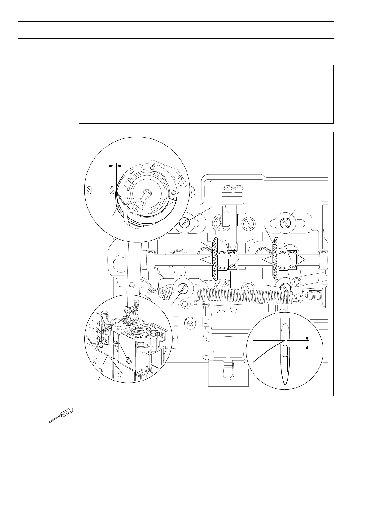
13.05.08 Hook clearance, needle rise, needle height and needle guard
Requirement
With the stitch length set at "3" and in needle-rise position (= 1.8 mm past b.d.c. on version
"B" or 2.0 mm past b.d.c. on version "C")
1. The hook point must be at the "needle centre" and the clearance between hook and
needle 0.05 to 0.1 mm,
2. the top end of the needle eye must be 0.8 to 0.1 mm below the hook point, and
3. needle guard 8 must touch the needle just lightly.
0.05 - 0.1 mm
1
8
6
2
7
3
6
23
1
7
1
1
4
5
0.8 - 1 mm
13 - 9
Fig. 11 - 08
● Set the stitch length at "3" and loosen screws 1, 2 and 3.
● Loosen screws 4 at the front and rear side.
● Position posts 5 according to Requirement 1.
● Tighten screws 1 and 4.
● Set the needle bar at b.d.c. and place the 1.8 or 2.0 mm thick feeler gauge close under
the needle bar bearing, move the screw clamp up against the feeler gauge and screw it
tight.
● Remove the feeler gauge and turn the balance wheel in sewing direction until the screw
clamp is against the needle bar bearing.
Page 13

Adjustment
● Set the hook point at the needle centre, making sure that the needle is not deflected by
needle guard 8.
● Making sure that bevel gear 6 is not too close, but the hook has not too much play,
tighten screws 2.
● Move fixing collar 7 up against bevel gear 6 and tighten screws 3.
● Adjust the needle height according to Requirement 2 (see also Chapter 13.04.04, Needle
height preliminary adjustment).
● position needle guard 8 according to Requirement 3.
After changing the needle clearance be sure to readjust the connecting linkage
of the thread trimmer mechanism (see also Chapter 13.05.6, Connecting
linkage).
13 - 10
Page 14

Adjustment
13.05.09 Top feed stroke
Requirement
With the longest top feed stroke set and the stitch length at "0", lifting presser 1 and
vibrating presser 2 must each rise from the needle plate by 7.0 mm when the balance
wheel is turned.
4
3
7 mm
2
1
7 mm
Fig. 11 - 09
● Set the longest top feed stroke and stitch length "0".
● Lower lifting presser 1.
● Turn the balance wheel in sewing direction until vibrating presser 2 has reached its
highest point.
● Turn crank 3 (srews 4) according to Requirement.
13 - 11
Page 15

13.05.10 Top feed lifting motion
Requirement
When lifting presser 1 is resting on the needle plate, vibrating presser 4 and needle point 5
must reach the needle plate at the same time at the highest top feed stroke.
Adjustment
2
3
5
1
4
Fig. 11 - 10
● Lower lifting presser 1 onto the needle plate.
● Loosen screws 2 just enough to allow eccentric 3 to be turned against a resistance on it
shaft.
● Turn eccentric 3 according to Requirement.
● Tighten screws 2.
13 - 12
Page 16

Adjustment
13.05.11 Bobbin case opener
Requirement
The needle thread must neither be trapped between bobbin case opener 3 and hook base
4 nor between position finger 5 and the retainer on the needle plate (see arrows).
2
6
5
1
3
4
Fig. 11 - 11
● Undscrew and remove post covers 1 (on left post from the rear).
● Undo screws 2 enough to allow bobbin case opener 3 to be turned on its shaft against a
resistance.
● Thread up the machine, place sewing material in and lower the lifting presser.
● Set bobbin case opener 3 according to Requirement.
● In this position, apply pressure on the bobbin case opener from the top, move clamp
collar 6 up against it and tighten screws 2.
13 - 13
Page 17

13.05.12 Slip coupling
Slip coupling 4 is adjusted at the works. When a thread jams, slip coupling 4
disengages, in order to avoid damage to the hooks. To engage the coupling
again, proceed as follows.
Adjustment
1
4
2
3
4
Fig. 11 - 12
● Remove jammed thread.
● Press plunger 1 and turn the balance wheel until pawl 2 engages groove 3.
13 - 14
Page 18

Adjustment
13.05.13 Needle-thread tension release
Requirement
With the lifting presser raised, there must be a clearance of at least 0.5 mm between
tension discs 4.
2
0.5 mm
1
3
4
Fig. 11 - 13
● Position pressure plate 1 behind mounting bracket 2 according to Requirement.
The clearance of 0.5 mm is a miminum setting and may be as much as 1 mm
for heavy threads.
When the tension is engaged, release pin 3 must not be under load.
13 - 15
Page 19

13.05.14 Thread check spring, without subclass -900/56
Requirement
The movement of thread check spring 5 must be finished when the needle pointe enters
the material (=spring stroke of about 7 mm).
Adjustment
7 mm
5
1
3
2
Fig. 11 - 14
● Adjust stop 1 (screw 2) according to Requirement.
● To adjust the pressure of the spring, turn screw 3 (screw 4).
For technical reasons the length of the thread check spring stroke may vary
upwards or downwards a little.
4
13 - 16
Page 20

Adjustment
13.05.15 Thread check spring on the PFAFF 1296 with subclass -900/56
Requirement
The movements of thread check springs 1 and 6 must be finished when the needle points
enter the material (=spring stroke of about 7 mm).
Fig. 11 - 15
810
5
1
6
7 mm
4
2
7
9
3
13 - 17
● To adjust the pressure of spring 1, turn screw 2 (screw 3).
● Adjust stop 4 (screw 5) according to Requirement.
● To adjust the pressure of spring 6, turn screw 7 (screw 8).
● Adjust stop 9 (screw 10) according to Requirement.
For technical reasons the length of the thread check spring stroke may vary
upwards or downwards a little.
Page 21

13.05.16 Bobbin winder
Requirement
1. With the bobbin winder engaged, drive wheel 1 must be driven reliably.
2. With the bobbin winder disengaged, friction wheel 5 must not run against drive wheel 1.
3. The bobbind winder must switch itself off when the filled thread is about 1 mm from
the rim of the bobbin.
Adjustment
1
Fig. 11 - 16
2
3
4
5
1 mm
● Re-position drive wheel 1 (screws 2) according to Requirements 1 and 2.
● Re-position pin 3 (screw 4) according to Requirement 3.
13 - 18
Page 22

Adjustment
13.05.17 Pressure of the lifting presser
Requirement
1. The material must be properly fed, even at the highest sewing speed.
2. There must be no pressure marks on the material.
1
13 - 19
Fig. 11 - 17
● Turn screw 1 according to the Requirement.
Page 23

13.06 Adjusting the thread trimmer -900/56
13
.06.01 Engaging solenoid
Requirement
1. Mounting bracket 1 must be in the middle of its adjusting range and parallel with the
right-hand edge of the mounting bracket.
2. When the thread trimmer is in its resting position the core of solenoid 3 must protrude
from the solenoid housing by about 4 mm.
4 mm
Adjustment
4
3
1
2
Fig. 11 - 18
● Re-position bracket 1 (screw 2) according to Requirement 1.
● Re-position solenoid 3 (screw 4) according to Requirement 2.
13 - 20
Page 24

Adjustment
13.06.02 Control cam (preliminary adjustment)
Requirement
1. Control cam 1, must be centred with the cutout of bearing mounting 5.
2. With the needle bar at t.d.c., screws 2 must be visible from the front and aligined
parallel with the bedplate.
2
4
4
3
3
1
5
Fig. 11 - 19
● Re-position control cam 1 (screws 2) and fixing collars 3 (screws 4) according to
Requirement.
13 - 21
Page 25

13.06.03 Control lever spring action
Requirement
When the thread trimmer is in its resting position, it must be possible to press control lever 3
about 1 mm towards the bedplate (spring action).
Adjustment
2
3
1
Fig. 11 - 20
● Turn screw 1 (nut 2) according to Requirement.
13 - 22
Page 26

Adjustment
13.06.04 Control lever stroke
Requirement
1. When engaging lever 5 is operated the pin of control lever 6 must drop freely into the
track of control cam 7.
2. After thread trimming, control lever 6 must pass freely on the right side of stop plate 3
and engage control lever 5 behind stop plate 3.
3. There must be a clearance of 0.2 mm between the pin of control cam 6 and the righthand inside of the control cam track.
0.2 mm
4
5
2
3
6
1
7
Fig. 11 - 21
● Re-position stop plate 1 (screws 2) and stop plate 3 (screws 4) according to
Requirement.
13 - 23
Page 27

13.06.05 Thread-trimmer drive linkage
Requirement
1. On the PFAFF 1296 thread-catcher drive linkage 1 must have a length of 128 mm, less
half of the needle gauge.
On the PFAFF 1295, thread catcher drive linkage 1 must have a length of 128 mm
2. When the threa trimmer is in its resting position there must be a clearance of about
1 mm between plunger 5 and lever 6.
128 mm
Adjustment
6
Fig. 11 - 22
1 mm
2
1
2
4
3
5
● Turn thread-catcher drive linkage 1 (nuts 2) to adjust it according to Requirement 1.
● Re-position bracket 3 (screw 4) according to Requirement 2.
13 - 24
Page 28

Adjustment
13.06.06 Linkage bar (only on the PFAFF 1296)
Requirement
The length of linkage bar 1 must be the same as the distance between the two threadcatcher drive shafts 3.
=
3
3
1
2
=
Fig. 11 - 23
● Adjust middle section 1 (nuts 2) of the linkage bar according to Requirement.
2
13 - 25
Page 29

13.06.07 Thread catcher height
Requirement
There must be a clearance of 0.7 mm between the underside of thread catcher 4 and
bobbin case cap 5.
4
5
Adjustment
0.7 mm
4
2
Fig. 11 - 24
● Loosen screws 1 and 2.
● Adjust the height of shaft 3 according to Requirement.
● Tighten screws 1.
Leave screws 2 loose for the following adjustment.
3
1
13 - 26
Page 30

Adjustment
13.06.08 Thread catcher resting position
Requirement
When the thread trimmer is in its resting poistion there must be a clearance of about 4
mm between the point of catcher 3 and the cutting edge of knife 4.
4 mm
3
3
4
1
2
13 - 27
Fig. 11 - 25
● Turn shaft 2 according to Requirement.
● Tighten screws 1.
When tightening screws 1 make sure that all transmission parts of the thread
catcher drive can move freely.
Page 31

13.06.09 Knife pressure
Requirement
When the front edge of thread catcher 3 has passed the knife cutting edge by half, knife 1
must rest with light pressure on the edge of the catcher.
Adjustment
3
2
3
1
Fig. 11 - 26
● Adjust knife 1 (screws 2) according to Requirement
13 - 28
Page 32

Adjustment
13.06.10 Bobbin thread trapping spring
Requirement
1. Bobbin thread trapping spring 3 must not be deflected by thread catcher 4 in any phase.
2. After the trimming action the bobbin thread must be securely trapped.
3. It must be possible to insert and remove the bobbin from the hook without any hindrance.
3
4
1
3
2
4
13 - 29
Fig. 11 - 27
● Re-position bracket 1 (screws 2) according to Requirements 1 and 3.
● Bend trapping spring 3 according to Requirement 2.
Page 33

13.06.11 Control cam (final adjustment)
Requirement
The trimming action must be just completed when the take-up lever is at t.d.c.
Adjustment
2
Fig. 11 - 28
● Turn control cam 1 (screws 2) according to Requirement.
1
13 - 30
Page 34

Adjustment
13.06.12 Release lever
Requirement
When the pin of control lever 3 has dropped into the track of control cam 4 and the needle
bar is at b.d.c. there must be a clearance of about 1 mm between control lever 3 and
release lever 5. In this position the needle thread tension must still be engaged.
4
5
3
1 mm
1
Fig. 11 - 29
● Turn eccentric 1 (screw 2) according to Requirement
2
13 - 31
Page 35

13.06.13 Release rod
Requirement
1. When the lifting presser is resting on the needle plate, pin 3 must rest at the lower end
of the elongated hole in pull-rod 1.
2. The tension discs must not be moved apart in this position.
Adjustment
2
1
3
Fig. 11 - 30
● Re-position pull-rod 1 (screws 2) according to Requirement.
1
13 - 32
Page 36

Adjustment
.07 Parameter settings
13
13.07.01 Parameter list
(only on machines with Quick-EcoDrive and control unit P40ED)
● The selection of the user level and the alteration of parameters is described in the separate
instruction manual for the drive unit.
Group
Parameter
Description
User lever
Setting
range
1 105 Speed for start backtack B, C 300 - 2000 600
110 Speed for end backtack B, C 300 - 2000 800
6 607 Speed max. B, C 300 - 6000 ▲
609 Cutting speed 1 B, C 60 - 300 180
7 700 Needle position 0 B, C 0 - 255 *
(needle reference position)
702 Needle position 1 (needle lowered) B, C 0 - 255 80
703 Needle position 2 (take-up lever raised) B, C 0 - 255 225
705 Needle position 5 (end cutting signal 1) B, C 0 - 255 100
706 Needle position 5 (start cutting signal 2) B, C 0 - 255 80
707 Needle position 9 (start thread tension B, C 0 - 255 195
release/start thread catcher)
Set value
13 - 33
722 Acceleration ramp B,C 1 - 60 45
723 Brake ramp B,C 1 - 60 40
734 Tact output A2 (thread trimming) B,C 001 - 009 0
760 Multiplier for the fixed value (200) for A, B, C 0 - 250 5
stitch count
799 Selected machine class C 1 - 4 2
▲
See Chapter 3 Specifications
*
Adjustment see Chapter 8.05 Basic position of the machine drive unit (in the machine
instruction manual)
Page 37

Adjustment
Group
8 800 Rotating direction of the motor C 0 - 1 1
9 900 Additional P- sensitivity of the B,C 1 - 24 10
Parameter
884 Proportional sensitivity of the B,C 03 - 24 12
897 Variant mini-motor, 1 = long, 2 = short C 0 - 1 1
Description
speed control unit
1295 B,C 03 - 24 12
1296 B,C 03 - 24 16
speed control unit
Further parameters and the description for an internet update of the machine
software and reset /cold start of the machine can be found in the instruction
manual for the control panel.
User lever
Setting
range
Set value
13 - 34
Page 38

Circuit diagrams
14.03 Circuit diagrams
Reference list for the Circuit diagrams
A1 Control unit Quick P40 ED
A2 Control panel BDF S2
A14 Sewing head recognition system (OTE)
H1 Sewing lamp (optional)
H10 LED stitch counter
M1 Sewing motor
Q1 Main switch
S1 Manual backtacking key
S1.1 Pedal speed control unit
S2 Needle position change key
S3 Single stitch key
S6 Start inhibitor (E6 stop)
X0 PC-interface (RS 232)
X1 Motor
X2 Incremental transducer
X2.1 Incremental transmitter adapter
X2.2 Synchronizer adapter
X2.3 Y5-911/.. backtacking device
X3 Speed control unit
X3.1 Y2-900/.. thread trimmer (FS )
X4 A2 control panel plug BDF S2
X4.1 Y4 -910/.. automatic foot lift
X5 Out-/input
X6 Bobbin thread monitor (optional)
X6.1 Y8 Thread tension release
X7 Photoelectric barrier (optional)
X22 Y2 -900/.. thread trimmer (FS )
X24 Y4 -910/.. automatic foot lift
X25 Y5 -911/.. backtacking device
X28 Y8 Thread tension release
X40 S1-3 Control panel
X50 A14 Sewing head recognition system (OTE)
14 - 1
Y2 -900/.. thread trimmer
Y4 -910/.. automatic foot lift
Y5 -911/.. backtacking device
Y8 Thread tension release
Page 39

91-191 502-95
Page 1 Version 07.07.06
Circuit diagram
14 - 2
Page 40

Circuit diagram
Version 07.07.06
91-191 502-95
Page 2
14 - 3
Page 41

91-191 502-95
Page 3 Version 07.07.06
Circuit diagram
14 - 4
Page 42

PFAFF Industriesysteme
und Maschinen AG
Hans-Geiger-Str. 12 - IG Nord
D-67661 Kaiserslautern
Phone: +49 - 631 200-0
Fax: +49 - 631 17202
E-mail: info@pfaff-industrial.com
Hotlines:
Technical service: +49 - 175/2243-101
Application consultance: +49 - 175/2243-102
Spare-parts hotline: +49 - 175/2243-103
Printed in Germany
 Loading...